

mbj DTL-ic-1020 Operating Manual
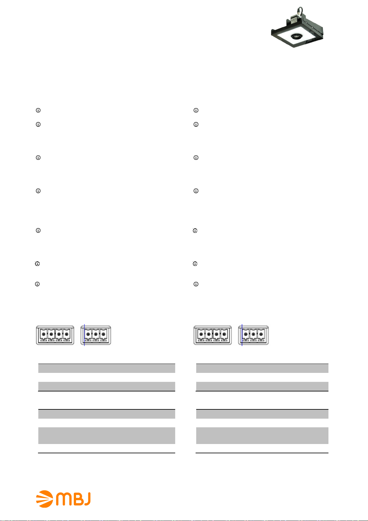
DTL-ic-1020 Diffuse Flat Dome Light
with flash controller and camera I/F
Note: Camera, cable and mount is not part of the product.
Bedienungsanleitung der diffusen DTL-ic-1020 Flat
Dome Beleuchtungen mit Blitzcontroller
1. Warn- und Anwendungshinweise
Bitte vor Verwendung des Gerätes die Warn- und
Anwendungshinweise sorgfältig durchlesen.
Allgemein - Das Gerät ist für nur die Verwendung in
Innenräumen ausgelegt.
Gesundheit - Ein direkter Blick in die Beleuchtung ist
grundsätzlich zu vermeiden. Bei Installations- und
Wartungsarbeiten ist die Beleuchtung vorher auszuschalten.
Das Gerät darf nicht verwendet werden, wenn ein Ausfall zu
einem Personenschaden führen kann.
Hitze - Bei unzureichender Wärmeableitung oder dem
Betreiben des Blitzmodus (über die CTR-Serie) als
Dauerlicht können Temperaturen größer 60°C auftreten. Es
ist auf ausreichendem Abstand zu leicht entflammbaren
Materialien zu achten.
Elektrischer Anschluss - Das Gehäuse ist von der Masse
der Spannungsversorgung elektrisch isoliert. Ein
Überschreiten der zulässigen Eingangsspannung Uin oder
das unzulässige Betreiben der Beleuchtung im Dauerlicht
kann zur Zerstörung des Gerätes oder zu einer erheblichen
Verkürzung der Lebensdauer des Gerätes führen.
Mechanischer Einbau - Für die Befestigung der
Beleuchtungseinheit sind vier Montagebohrungen mit
Gewinde vorgesehen. Bitte die max. Einschraubtiefe nicht
überschreiten. Es kann zur Zerstörung des Gerätes führen.
Es ist auf ausreichende Wärmeableitung zu achten.
Benutzungshinweise – Bitte vermeiden Sie in Betrieb eine
mechanische Beanspruchung der Leuchtfläche. Dies kann
zu Kratzern und einem inhomogenen Lichtaustritt führen.
Reinigung – Die Leuchtfläche darf nur mit einem
handelsüblichen Glasreiniger und einem weichen Putzlappen
gereinigt werden.
2. Elektrische Anschlüsse
Die Beleuchtung wird mit zwei Steckkontakten und
zugehörigen Steckern geliefert.
Operating Manual of the DTL-ic-1020 diffuse flat dome
lighting with flash controller
1. Cautions and instructions for use
Please read the warning and application instructions carefully
before using the backlight.
General - The device is designed for indoor use only.
Health – Strictly avoid looking directly into the light source.
The lighting must be switched off before the installation
and/or maintenance. The device must not be used when a
failure may cause a personal injury.
Heat - In case of insufficient heat dissipation or supplying
to the device the max. flash voltage (Ub) is a continuous
operating mode (via the CTR series or directly) the surface
temperature may exceed 60 °C. Keep off flammable
materials at any time.
Electricity - The housing is electrically isolated from the
ground of the power supply. Exceeding the permissible input
voltage Uin or using the unit for continuous light application
can lead to the destruction of the device or to a significant
shortening of the lifetime of the LEDs of the device.
Mechanical integration - 4 screw-in tape holes can be used
to fix the lighting to specified position. It is essential to ensure
adequate heat transfer at the holding position. Please do not
exceed the maximum screw-in depth. I could destroy the
unit.
Usage – Please prevent during operation mechanical
stress to the light surface. This could lead to scratches and
inhomogenious light emission.
Cleaning - The light emission surface has to be cleaned
with a standard glass cleaner and a soft cleaning cloth only.
2. Electrical connection
The lighting is supplied with two plug-contacts and two plug
adapter as counter parts.
Pin4 Pin3 Pin2 Pin1 Pin3 Pin2 Pin1
Pin
1
2
3
Interface nach Extern
Masse
Uin = 24V DC
I/O-In Signal (zur Kamera)
Pin
1
2
3
Interface zur Kamera
Masse
Uout = 12V DC (Kamera Power)
I/O-Out Signal zur Blitzsteuerung
(Offen=Aus, Masse=An)
4
1) Bitte die Verwendung des Exposure Active Signals der Kameraanleitung entnehmen.
2) Unterstützung von ‚open collector‘ I/O-Ausgängen, PullUp-R ist bereits integriert.
I/O-In Signal (von Extern)
1) 2)
MBJ Imaging GmbH
Neuer Höltigbaum 15
DE 22143 Hamburg
Pin4 Pin3 Pin2 Pin1 Pin3 Pin2 Pin1
Pin
1
2
3
Pin
1
2
3
4
1) Please check camera manual how to activate the exposure active signal,
2) Support for ‘open collector’ I/O-outputs, pull-up resistor already integrated.
support@mbj-imaging.com
www.mbj-imaging.com
Tel.: +49 40 226 1623 30
External interface
Ground
Uin = 24V DC
I/O-In signal (camera loop)
Camera interface
Ground
Uout = 12V DC (camera power)
I/O-Out signal (flash control)
(Open=Off, GND=On)
I/O-In signal (camera loop)
1) 2)
DTL-ic-1020 Series
Release: 1.04
21.02.2017
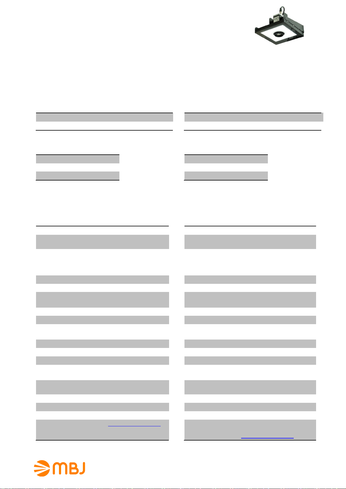
DTL-ic-1020 Diffuse Flat Dome Light
3. Betriebsmodus
3.
Operating mode
with flash controller and camera I/F
Note: Camera, cable and mount is not part of the product.
Die Beleuchtung ist ausschließlich für den Blitzbetrieb ausgelegt. Die Blitzdauer wird über das I/O-Out-Signal der
Kamera bestimmt. Bei Bedarf kann die Grundhelligkeit über
einen internen Dimmer nachgeregelt werden.
4. Modellübersicht / LED-Farbe
LED Modell Wellenlänge
Weiß DTL-ic-1020-WT Spitze bei 460nm & 560nm
Rot DTL-ic-1020-RD Spitze bei 625nm
5. Strombedarf
Mode Weiß Rot
50%1) 900mA 900mA
75%2) 1800mA 1500mA
100%3) max 3.1A max 2.7A
1) Blitzbetrieb mit <1000ms Blitzzeit
2) Fabrikeinstellung, Blitzbetrieb mit < 30% Auslastungsgrad <100ms Blitzzeit
3) Blitzbetrieb mit < 10% Auslastungsgrad <1ms Blitzzeit
6. Allgemeine Spezifikation
Leuchtfläche (axb) 100mm x 200mm
Lichtabstrahlung Auflicht mit 36mm Loch und
diffuser Abstrahlung
Empfohlener
Objektabstand
100mm bis 200mm,
abhängig vom Abbildungsmaßstab, der Objektgröße und
der Beleuchtungsart
Betriebsspannung (Uin) 24V DC +/- 10%
Betriebsarten Kameragesteuerter Blitzbetrieb
Unterstützte Kameras Basler ace (GigE & USB3.0)
und weitere
Min. Blitzverzögerung Ca. 1 µs
Min. Blitzzeit Ca. 5 µs
Max. Pulsleistung WT: 22W (50%) / 84W (100%)
RD: 22W (50%) / 65W (100%)
Kameraausgang 12V DC, max. 400mA
Abmessungen 230mm x 140mm x 12mm
Gewicht 750g
Anschluss 3Pin Steckkontakt, RM3,81
4Pin Steckkontakt, RM3,81
Umgebungs-
10°C bis 30°C
temperatur
Schutzart IP54
Schutzklasse DIN EN 60825-1 Klasse 1
Luftfeuchtigkeit 30% bis 70%
Zubehör Siehe www.mbj-imaging.com
Webseite für diverse Kabel,
Halter und LED-Controller
The illumination is made for flash light usage only. The flash
duration is controlled by the I/O-out signal of the camera. If
necessary the brightness can be controlled by an internal
dimmer.
4. Model Range / LED Color
LED Model wave length
White DTL-ic-1020-WT peak near 460nm & 560nm
Red DTL-ic-1020-RD peak near 625nm
5. Operating current
mode White Red
50%1) 900mA 900mA
75%2) 1800mA 1500mA
100%3) max 3.1A max 2.7A
1) pulse mode with <1000ms flash time
2) Factory default, pulse mode with < 30% duty cycle and <100ms flash time
3) Pulse mode with < 10% duty cycle and <1ms flash time
6. General Specification
Luminous area (axb) 100mm x 200mm
Light emission
Recommended
object distance
Diffuse incident light from
above with 36mm hole
100mm to 200mm,
depending on reproduction
scale, the size of the object
and the type of illumination.
Operating voltage (Uin) 24V DC +/- 10%
Operating mode Camera controlled flash light
Supported cameras Basler ace/USB3.0
and more
Min. flash delay Approx. 1 µs
Min. flash duration Approx. 5 µs
Max. pulse power
WT: 22W (50%) / 84W (100%)
RD: 22W (50%) / 65W (100%)
Camera Power 12V DC, max. 400mA
Dimensions 230mm x 140mm x 12mm
Weight 750g
Connector 3Pin male contact, RM3.81
4Pin male contact, RM3.81
Operating
10°C to 30°C
temperature
Degree of protection IP54
Protection class DIN EN 60825-1 class 1
Humidity 30% to 70%
Accessories For cable, mounts and LED
controller please check
www.mbj-imaging.com
MBJ Imaging GmbH
Neuer Höltigbaum 15
DE 22143 Hamburg
support@mbj-imaging.com
www.mbj-imaging.com
Tel.: +49 40 226 1623 30
DTL-ic-1020 Series
Release: 1.04
21.02.2017
 Loading...