

MB Connect Line mbNET.mini User Manual
.
User Manual
Version: 1.6.0 DR 03 (10.01.2017) - EN
Page 2 of 90 | Version: 1.6.0 DR 03 (10.01.2017) - EN | 10.01.2017
By purchasing the mbNET.mini router, you have chosen a product made in Germany.
Our products are produced exclusively in Germany, which guarantees the highest quality and safeguards jobs
in Europe.
The latest information and updates can be found on our homepage www.mbconnectline.de.
We welcome comments, suggestions for improvement or constructive criticism at any time.
Hereby MB CONNECT LINE acknowledges that the device mbNET.mini (MDH86xx) is in complies with the
essential requirements and other relevant provisions of directive 1999/5/EC. The declaration of conformity can
be found at: www.mbconnectline.com
Issued by:
MB Connect Line GmbH
Fernwartungssysteme
Winnettener Str. 6
91550 Dinkelsbühl, Germany
Tel:
+49 (0) 700 622 666 32 /
+49 (0) 700MBCONNECT
Website:
www.mbconnectline.com
Copyright © MB Connect Line GmbH 2015
No part of this document and its contents may be reproduced, used or distributed without our express permis-
sion. Damages will be claimed in the event of infringement. All rights reserved.

Table of contents | Page 3 of 90
Table of contents
1 General................................................................................................................................................... 6
2 Safety instructions................................................................................................................................8
3 Legal information..................................................................................................................................8
4 Notes on Cyber-Security......................................................................................................................9
5 Functional Overview...........................................................................................................................10
6 Included in delivery............................................................................................................................11
7 Displays, controls and connections.................................................................................................12
8 Interface assignment..........................................................................................................................14
8.1 Pinout of the terminal block on the bottom of the device...........................................................14
8.2 Pinout of LAN/WAN ports on the front panel of the device........................................................14
8.3 Pinout of the USB port on the front panel of the device............................................................ 14
9 Getting started.....................................................................................................................................15
10 Initial configuration.............................................................................................................................16
10.1 Initial configuration via RSP mbCONNECT24 V 2.0..................................................................17
10.1.1 Account request - Software download........................................................................... 18
10.1.2 Connect to RSP mbCONNECT24..................................................................................19
10.1.3 mbCONNECT24 Configuration.......................................................................................20
10.1.3.1 Changing your password.............................................................................................20
10.1.3.2 Creating a project........................................................................................................20
10.1.3.3 Create a new device................................................................................................... 22
10.1.3.4 Create a configuration.................................................................................................23
10.1.3.4.1 LAN Settings.............................................................................................................24
10.1.3.4.2 WiFi Settings.............................................................................................................25
10.1.3.4.3 Internet Settings........................................................................................................27
10.1.3.4.4 WAN Settings........................................................................................................... 29
10.1.3.4.5 Modem Settings........................................................................................................30
10.1.4 Transferring the configuration to the Device..................................................................31
10.1.4.1 Download to PC..........................................................................................................32
10.1.4.1.1 Importing the configuration into the mbNET.mini.....................................................32
10.1.4.2 Prepare for Synchronization........................................................................................33
10.1.4.3 Transferring configuration to the device - via mbDIALUP...........................................34
10.1.5 Access to devices and machines...................................................................................35
10.1.6 Quit the mbCONNECT24 session..................................................................................35
10.2 Initial configuration via mbCONNECT24 V 1.x...........................................................................36
10.2.1 Adding a new device (mbCONNECT24 V 1.x)..............................................................37
10.2.1.1 Description - all devises..............................................................................................38
10.2.1.2 Network (MDH 860, 861, 862, 863)............................................................................39
10.2.1.3 Internet.........................................................................................................................40

Page 4 of 90 | Version: 1.6.0 DR 03 (10.01.2017) - EN | 10.01.2017
10.2.1.3.1 WAN device (MDH 860)...........................................................................................40
10.2.1.3.2 WAN device (MDH 861, 862)...................................................................................41
10.2.1.3.3 WiFi device (MDH 863)............................................................................................42
10.2.2 Transferring the configuration to mbNET.mini................................................................43
10.2.2.1 Download configuration to PC - via USB....................................................................44
10.2.2.2 Transfer configuration to the device - via CTM...........................................................45
10.2.2.3 Transferring configuration to the device - via mbDIALUP...........................................46
10.3 Initial configuration via the web interface of the mbNET.mini....................................................47
10.3.1 Firststart..........................................................................................................................47
10.3.2 Device State................................................................................................................... 52
10.3.2.1 Five Step Status Check...............................................................................................53
10.3.3 Diagnostics......................................................................................................................56
11 Configuring Your Router in the Portal (V 1.x)................................................................................. 57
11.1 System > Settings.......................................................................................................................58
11.1.1 System Settings..............................................................................................................58
11.1.2 Time Settings..................................................................................................................58
11.1.3 Mail Settings...................................................................................................................59
11.2 System > WEB...........................................................................................................................59
11.3 System > USB............................................................................................................................60
11.4 System > Logging.......................................................................................................................61
11.5 Security > Firewall General........................................................................................................62
11.6 Security > WAN>LAN................................................................................................................. 63
11.7 Security > LAN>WAN................................................................................................................. 64
11.8 Security > Forwarding.................................................................................................................65
11.9 Security > NAT...........................................................................................................................66
11.10 Alarmmanagement > Input......................................................................................................... 67
11.11 Passwords (Password Settings).................................................................................................68
12 Configuring your Router in the Remote Service Portal (V 2.x)......................................................69
12.1 System Settings..........................................................................................................................70
12.2 Mail Settings............................................................................................................................... 71
12.3 Firewall........................................................................................................................................72
12.3.1 Firewall Settings............................................................................................................. 72
12.3.2 Firewall Rules.................................................................................................................73
12.4 Alarmmanagement......................................................................................................................74
12.5 VPN.............................................................................................................................................75
12.6 User Administration.....................................................................................................................76
12.7 NTP Server.................................................................................................................................77
12.8 Time Zone...................................................................................................................................78
12.9 Web Server.................................................................................................................................79
12.10 Direct Device Web2go................................................................................................................80
12.11 Logging........................................................................................................................................81
13 Loading the factory settings............................................................................................................. 82
14 Firmware update................................................................................................................................. 83

| Page 5 of 90
14.1 Firmware update via USB.......................................................................................................... 84
14.2 Firmware update via RSP mbCONNECT24...............................................................................85
15 Technical Data.....................................................................................................................................86
15.1 Technical data MDH 860............................................................................................................86
15.2 Technical data MDH 861............................................................................................................87
15.3 Technical data MDH 862 AT&T.................................................................................................88
15.4 Technical data MDH 862 EU......................................................................................................89
15.5 Technical data MDH 863............................................................................................................90

Page 6 of 90 | Version: 1.6.0 DR 03 (10.01.2017) - EN | 10.01.2017
1 General
Purpose of this documentation
This user manual describes the functions and use of the mbNET.mini router MDH86x.
Please read carefully and retain this information.
Validity of this documentation
This manual is valid for the router mbNET.mini MDH 860, MDH 861, MDH 862, MDH 863, from firmware
version V 1.5.
Prerequisites / additional required components
The following end devices are suitable for connecting to the mymbCONNECT24.virtual server:
•
standard Windows PC with network interface (ethernet interface)
•
USB srick recommended format: FAT32 or ext3; recommended maximun size: 4 GB (FAT32), 16 GB
(ext3)
•
network cable
•
internet access
Additional required software
•
mbCONNECT24 *
mbCONNECT24 is the central portal for secure remote maintenance on the internet.
•
mbDIALUP * from version V 3.1
mbDIALUP is the remote client to establish a secure VPN connection to the portal mbCONNECT24
•
mbCHECK * from version V 1.1.2
The program checks that at least one of the 80TCP, 443TCP or 1194TCP ports is enabled in the firewall. At least mbDIALUP and a device (mbNET/mbSPIDER) for connection to the platform need one of
these ports. You will then be notified whether connection via mbDIALUP to the platform is possible.
* The latest version can be downloaded from www.mbconnectline.com.
Release notes:
Version Date Comment
V 1.6 2016 / 04 / 04 Previous version V 1.3
V 1.6 DR 01 2016 / 06 / 09 Adaptation of Technical Data: Pollution degree, Area of application (Alti-
tude), Temperature range.
V 1.6 DR 02 2016 / 06 / 16 Error correction in Chapter 7 Display, controls and connections "Con LED
lights" - Description (only in the German language version).
V 1.6 DR 03 2017 / 01 / 10 Chapter 10.1.3.4.1 LAN Settings and 10.1.3.4.4 WAN Settings: changed
screenshots.
Additional documentation
•
First steps mbCONNECT24
This document describes the initial steps and actions that are necessary to connect a device (mbNET/mbSPIDER) to the portal with the remote client mbDIALUP.

General | Page 7 of 90
Currently manuals and more information
The latest manuals and more information about products related to secure remote maintenance can be found
on www.mbconnectline.com in the download portal.

Page 8 of 90 | Version: 1.6.0 DR 03 (10.01.2017) - EN | 10.01.2017
2 Safety instructions
•
The router is built to the latest technological standards and recognized safety standards (see Declaration of Conformity).
•
The router must be installed in a dry location. No liquid must be allowed to get inside the router, as this
could result in electric shocks or short circuits.
•
The router is for indoor use only.
•
Never open the router chassis. Unauthorized opening and improper repair can pose a danger to the
user. Unauthorized modifications are not covered by the manufacturer's warranty. Opening up the device voids the warranty.
•
The router must be disposed of in line with European regulations and German legislation on electronics
and electronic devices and not in general household waste. The device should be disposed of accordingly.
In the present operating instructions the following symbols / warnings are used:
An advice signifies additional information and indications such as cyber-security that
assists in the assured handling with the system.
This symbol indicates a possible risk of damage to hardware and / or software.
3 Legal information
Qualified Personnel
The product/system described in this documentation may be operated only by personnel qualified for the specific task in accordance with the relevant documentation, in particular its warning notices and safety instructions. Qualified personnel are those who, based on their training and experience, are capable of identifying
risks and avoiding potential hazards when working with these products/systems.
Proper use
The mbNET.mini router may be used only as described in the manual.
Disclaimer
In this manual all technical information, data and instructions for installation, operation and maintenance are
based on our previous experience and insights to the best knowledge. For the details, illustrations and descriptions in these instructions, no claims can be deduced. We assume no liability for damage due to:
•
disregard of these operating instructions
•
improper use
•
technical modifications
Translations are performed best of our knowledge. We do not assume no liability for translation mistakes, even
if the translation was carried out by us or on our behalf. Binding remains solely the original German text.
Subject to technical and content changes.
Trademarks
The use of any trademark not listed herein is not an indication that it is freely available for use.

Notes on Cyber-Security | Page 9 of 90
4 Notes on Cyber-Security
Note the following safety recommendations in order not to prevent unauthorized access to the system.
General
•
Make sure at regular intervals that all relevant components these recommendations and, if necessary,
meet other internal security guidelines.
•
Evaluate your system holistically in terms of safety. Take a cell protection concept with corresponding
products.
see for example "ICS Security Compendium" by Federal Office for Information Security (BSI-Germany)
https://www.bsi.bund.de/SharedDocs/Downloads/EN/BSI/ICS/ICS-Security_compendium.html
shortened URL: http://bit.ly/1QXbuuZ
Physically access
•
Restrict physical access to safety relevant components to qualified personnel.
Security functions of the software
•
Keep the software / firmware up to date.
°
Inform yourself periodically about security updates of the product. Information, please visit: www.mbconnectline.com
°
Inform yourself periodically about product updates. Information, please visit: www.mbconnectline.com
Passwords
•
Define rules for the use of equipment and assigning passwords.
•
Regularly change the passwords to increase security.
•
Always use passwords with high strength password. Avoid weak passwords such. B. "password1",
"123456789" or the like.
•
Make sure that all passwords are protected and inaccessible to unauthorized personnel.
•
Never use one password for different users and systems.

Page 10 of 90 | Version: 1.6.0 DR 03 (10.01.2017) - EN | 10.01.2017
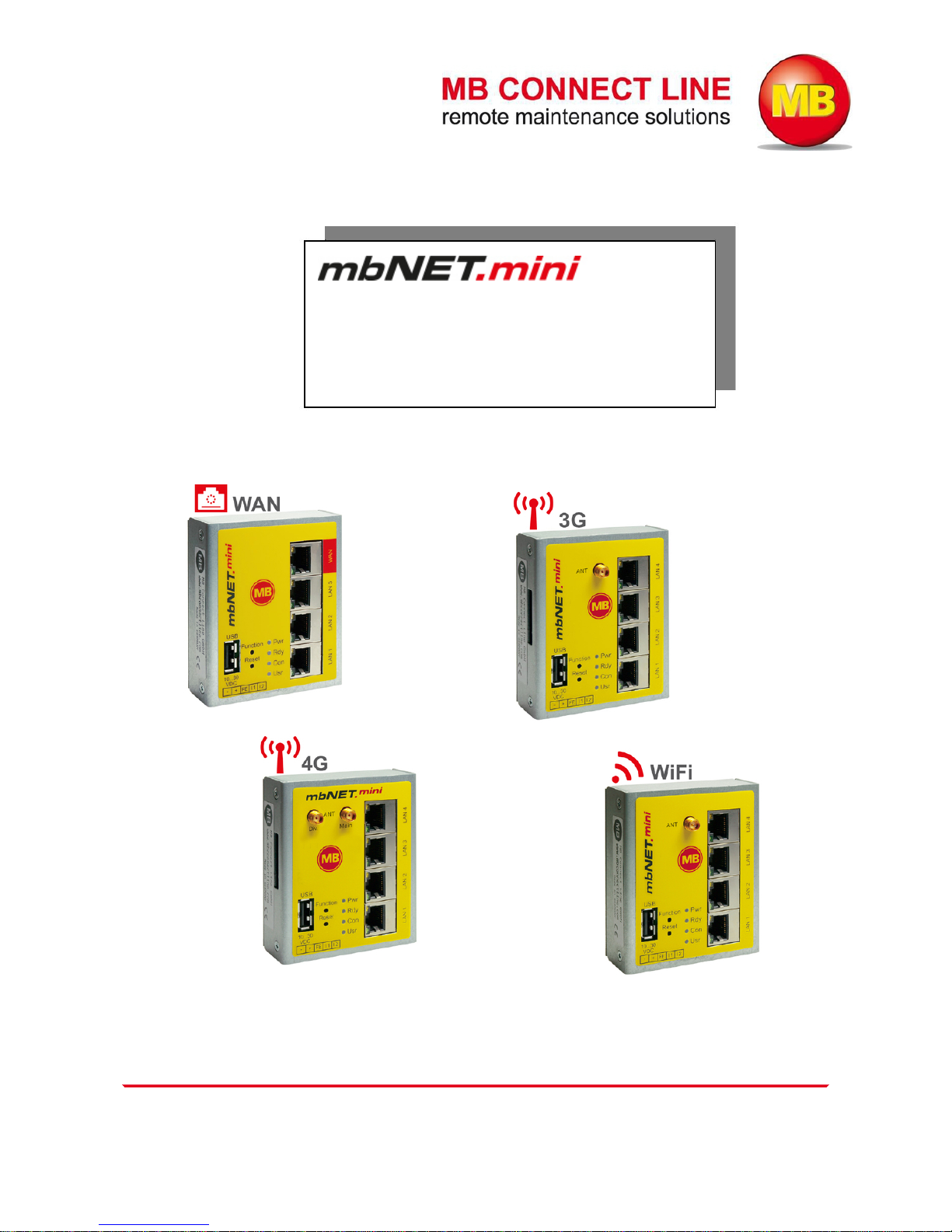
5 Functional Overview
Brief description
The industrial router mbNET.mini offers you optimum flexibility and security, making remote communication
with your systems both easy and secure. Thanks to its compact design, the mbNET.mini router will fit into
any switch cabinet and provides the perfect system for connecting to different components. The router can be
configured via the portal mbCONNECT24 (mymbCONNECT24.mini, -.midi, -.maxi, -.hosted, -.virtual).
Performance characteristics
•
The router can be fully configured via the portal mbCONNECT24, mymbCONNECT24.mini, -.midi,
-.maxi, -.hosted, -.virtual.
•
Can connect to machines and systems via LAN, WAN, WiFi or modem.
•
Deployable worldwide using mobile communications plus access via LAN and Internet.
•
Secure connection using an integrated firewall with IP filter, NAT, port forwarding and VPN with AES,
DES/3DES and Blowfish encryption.
•
Two digital inputs to initiate the connection to the portal server or send a warning text message/email.
Included in delivery | Page 11 of 90
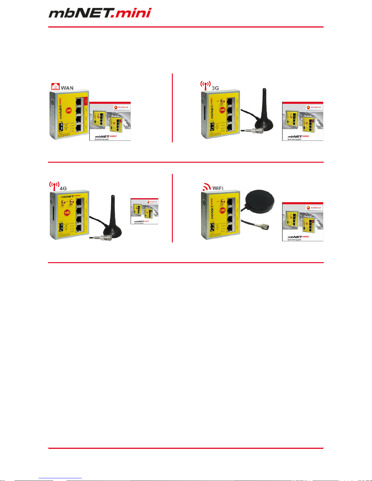
6 Included in delivery
Please check that your delivery is complete:
MDH 860 MDH 861
Quick Start Guide GSM antenna Quick Start Guide
MDH 862 MDH 863
Quick Start Guide GSM antenna Quick Start Guide
Should any of these parts are missing or damaged, please contact the following address:
MB CONNECT LINE GMBH
Winnettener Str. 6
D-91550 Dinkelsbühl
Tel.: +49 (0)9851/282529-0
Fax: +49 (0)9851/282529-99
Please keep the original box and the original packaging in case you need to send the device for repair at a
later date.
Page 12 of 90 | Version: 1.6.0 DR 03 (10.01.2017) - EN | 10.01.2017
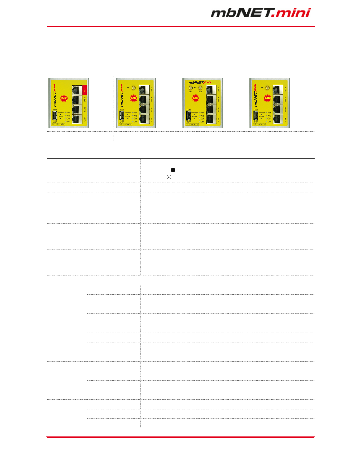
7 Displays, controls and connections
View of front of the device
MDH 860 MDH 861 MDH 862 MDH 863
1 x WAN; 3 x LAN; USB GSM 3G; 4 x LAN; USB GSM 4G; 4 x LAN; USB WAN; 4 x LAN; USB
Designation Status Description
ANT -
SMA antenna connector:
SMA female (MDH 861, MDH 862)
SMA male (MDH 863)
Main - SMA antenna connector for use with one antenna
Div. -
SMA antenna connector (combined with "Main") of
•
a second antenna (macrodiversity)
•
a MIMO antenna (microdiversity)
LED off
Device power source is switched off or device is not connected to power
source/power pack.
Pwr (Power)
LED on Power source is connected to terminal block and switched on.
LED flashing
After the system has been checked and started (duration approx. 25 sec),
the LED flashes for the duration of the starting up process (approx. 90 sec).
Rdy (Ready)
LED on The device is ready for operation.
This LED shows whether the device is connected to the Internet and the portal server.
LED off No connection to Internet or portal.
LED flashing (3Hz) Internet or VPN connection being established.
LED flashing (1,5Hz) Connection to portal server has been established.
Con (Connect)
LED on Connection to the Internet has been established.
LED flashing (3Hz) Firmware on USB stick ready to be updated.
LED flashing (1,5Hz) Portal configuration on USB stick ready to be transferred.Usr (User)
LED on Firmware or configuration is being copied to the device.
WAN - Router WAN connection (customer network, DSL router).
Orange LED flashing Network data transfer active
Green LED on Transfer rate = 100 MBit/sWAN-LED
Green LED off Transfer rate = 10 MBit/s
LAN 1 - 4 - Local network connection (e.g. machine network, network data transfer).
Orange LED flashing Network data transfer active
Green LED on Transfer rate = 100 MBit/sLAN-LED 1 – 4
Green LED off Transfer rate = 10 MBit/s
| Page 13 of 90
Designation Status Description
USB -
Transfer of configuration from USB stick to mbNET.mini.
Transfer of firmware from USB stick to mbNET.mini.
Access to free application data via SFTP.
Function This button has three functions and is used according to the status.
-
1 Establishing connection to portal (depending on configuration)
2 Accepting firmware or configuration from USB stick
3 Loading factory settings
Reset - Pushing this button restarts the device (so-called cold start).
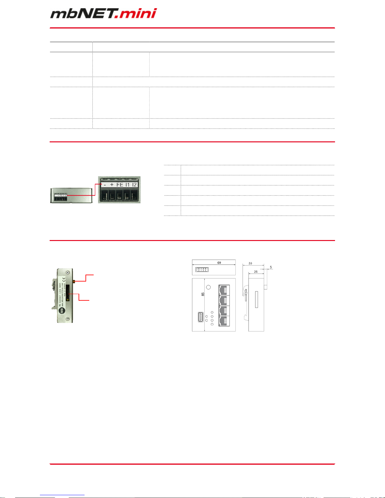
View of bottom of device
- 0 V DC connection
+ Power source connection 10 - 30 V DC
FE Functional earth
I 1* Digital input I1 (10 - 30 V DC)
I 2** Digital input I2 (10 - 30 V DC)
* Input 1 can only be configured for establishing the connection to the portal mbCONNECT24.
** Input 2 can be cofigured to send emails, SMS, Internet SMS or to start a reboot.
View of device from left Device dimensions
Antenna connection
SIM-card slot
Page 14 of 90 | Version: 1.6.0 DR 03 (10.01.2017) - EN | 10.01.2017
8 Interface assignment
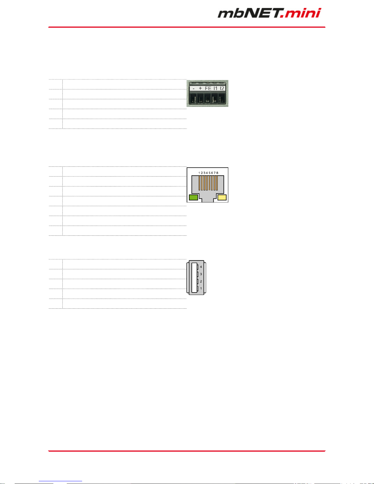
8.1 Pinout of the terminal block on the bottom of the device
- 0V DC connection
+ Power source connection 10-30V DC
FE Functional earth
I1 Digital input I1 (10-30V DC)
I2 Digital input I2 (10-30V DC)
* Input 1 can only be configured for establishing the connection to the portal mbCONNECT24.
** Input 2 can be cofigured to send emails, SMS, Internet SMS or to start a reboot.
8.2 Pinout of LAN/WAN ports on the front panel of the device
Signal
1 TX+
2 TX-
3 RX+
4 Not connected
5 Not connected
6 RX-
8.3 Pinout of the USB port on the front panel of the device
Signal
1 VCC (+5V)
2 - Data
3 +Data
4 GND
Getting started | Page 15 of 90
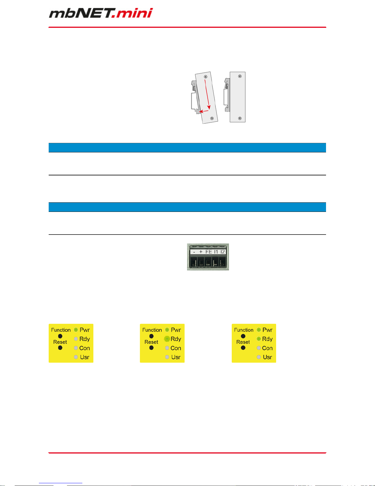
9 Getting started
The device is intended to be installed in switch cabinets and designed to be mounted on top-hat rails (according to DIN EN 50 022).
Insert the device into the DIN rail.
To do this, position the upper guide of the bracket on
the rail on the back of the device and then press the
device downwards against the rail until fully inserted.
Depending on the device, connect an antenna, and insert a SIM card.
ADVICE
The SIM card used must be Internet- / VPN-enabled. If you have any questions, contact your cell phone
operator.
Connect the mbNET.mini to the power supply
ADVICE
Before connecting the device to a network or PC, first ensure that it is properly connected to a power supply,
otherwise it may cause damage to other equipment. You should therefore follow the instructions given below.
Connect equipotential bonding to the functional earth
(FE).
Connect the mbNET.mini to a power supply (10 – 30
VDC).
Make sure the polarity is correct!
After turning on the power supply, the LED Pwr lights up.
As soon as the system has been checked and started (duration approx. 25 sec), the Rdy LED flashes for the
dura-tion of the starting up process (approx. 90 sec).
The mbNET.mini is now ready for operation.
T 0 T + 25 sec T + 90 sec
For further support on the mbNET.mini, visit our website on www.mbconnectline.com.

Page 16 of 90 | Version: 1.6.0 DR 03 (10.01.2017) - EN | 10.01.2017
10 Initial configuration
Because the mbNET.mini was designed as a portal device, the initial start-up takes place via the web portal
•
RSP mbCONNECT24 V 2.x
oder
•
mbCONNECT24 V1.x
Generally following procedure applies:
•
Add the mbNET.mini in the portal as a new device.
•
Enter the necessary basic data, so that the device can connect to the portal (for example, device
name, network settings, connection information, etc.).
•
Transfer the device configuration from the portal into the mbNET.mini.
Alternatively, you can enter the necessary connection basic data direct on the web interface of the device (see chapter: Initial configuration via the web interface of the mbNET.mini).
Initial configuration | Page 17 of 90
10.1 Initial configuration via RSP mbCONNECT24 V 2.0
If you not have an account for the
remote service portal, here given
the necessary information on how
to request your access to mbCO-
NENCT24 and how you connect to
the portal.
Here you can see how to create a
device and perform the initial configuration for your mbNET.mini.
In this section you will learn the different methods, how to transfer
the initial configuration to the mb-
NET.mini.
In the last section we show you how
to connect to devices and machines,
and how you finish your mbCON-
NECT24 session tidy.

Page 18 of 90 | Version: 1.6.0 DR 03 (10.01.2017) - EN | 10.01.2017
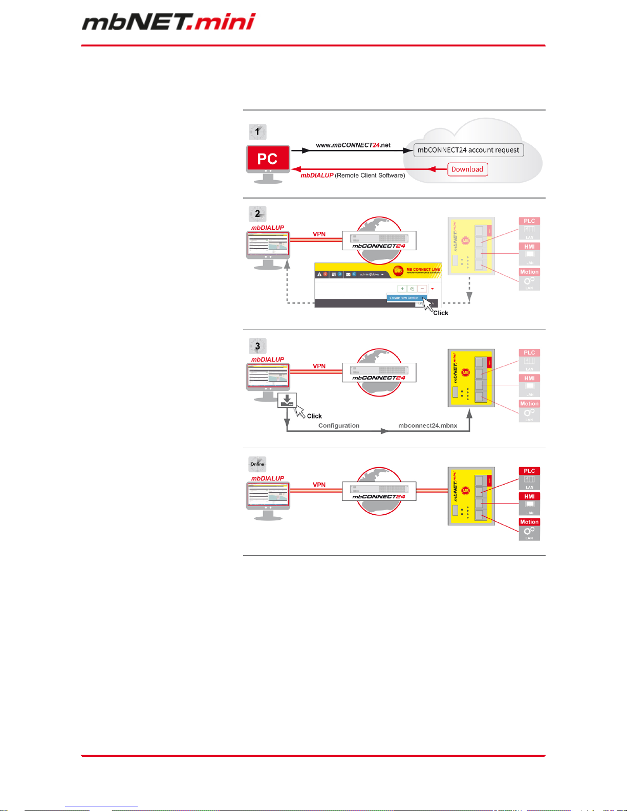
10.1.1 Account request - Software download
If you do not have an account for mbCONNECT24 :
•
Go to www.mbconnect24.net or www.mbconnectline.com.
•
Click the button
"mbCONNECT24 account request"
The button you find above the navigation
menue at the top of the screen.
Nach erfolgter Anmeldung erhalten Sie a) eine Bestätigungs-Mail mit Ihrem Benutzernamen
b) eine zweite E-Mail mit Ihrem Passwort
Software download
To establish a secure VPN connection to the portal mbCONNECT24you require the
remote client software mbDIALUP.
In our download portal downloads.mbconnectline.com you can mbDIALUP download in the current version
for free.
Run, after extracting the ZIP file, the program "setupmbdialup.exe".
ADVICE
During the installation process, you must ensure that you are logged in as Administrator.
ADVICE
Get an indication of the software to be installed by "Eltima" (Virtual Serial Port Driver), you agree to the
installation. Eltima is required to create the virtual COM ports.
Initial configuration | Page 19 of 90
10.1.2 Connect to RSP mbCONNECT24
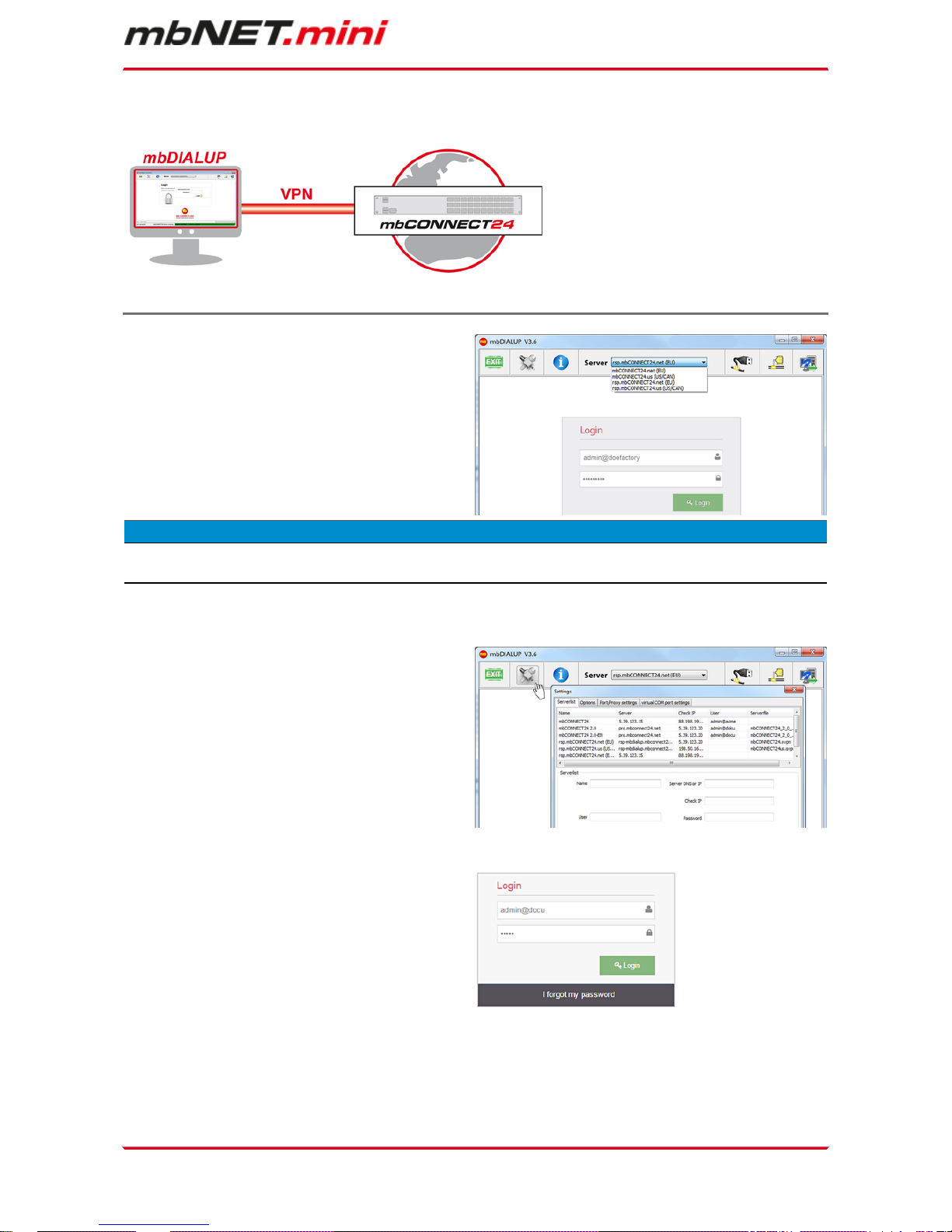
Selecting the server
Start mbDIALUP and select from the pull-down menu
"Server" your mbCONNECT24 server.
•
rsp.mbconnect24.net (EU)
for server location EUROPE
•
rsp.mbconnect24.us (US/CAN)
for server location USA/Canada
ADVICE
The server location can be seen in the confirmation email for subscibing to mbCONNECT24.
Access via the proxy server
If the Internet can only be accessed via a proxy server, the relevant settings can be applied in the menu
"Settings", submenu "Port/Proxy settings".
Login mbCONNECT24
You can now log in to the portal with the user data
(username, password) that were sent to you when
you registered.
A secure VPN connection to your account on mb-
CONNECT24 is now established.
Page 20 of 90 | Version: 1.6.0 DR 03 (10.01.2017) - EN | 10.01.2017
10.1.3 mbCONNECT24 Configuration
Here you do
•
change your password
•
create a new project
•
create a new device
•
generate a configuration file and
•
transfer it to your mbNET or mbSPIDER
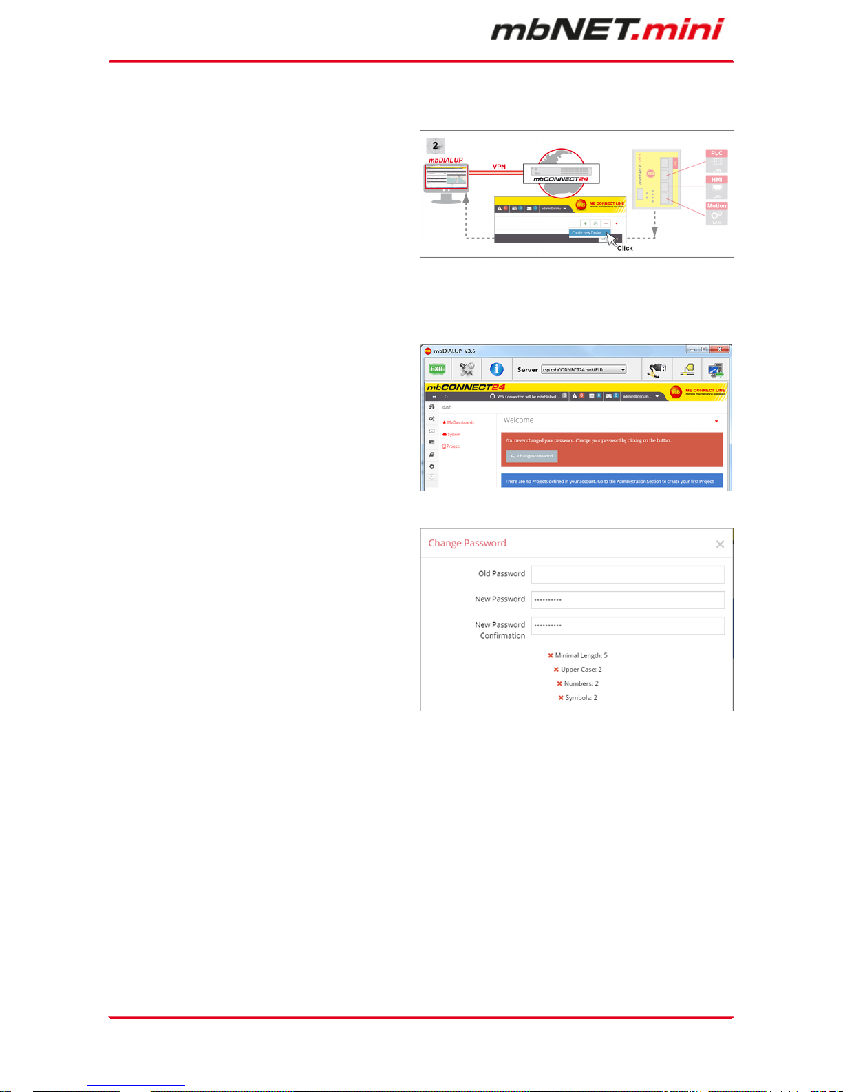
10.1.3.1 Changing your password
After your first Login at the portal, you are required to
change your password.
This is a safety-related matter and should definitely
be completed.
Unless you change your password, this prompt is
displayed at each call of home page.
Click on "Change Password".
Notice that your password has to fit the password
guideline.
Your password is active, when you reconnect to the
portal.
10.1.3.2 Creating a project
A project is the highest entity to implement the following tasks:
•
remote maintenance
•
monitoring and alarming
•
data-logging
•
visualization
A device (mbNET/mbSPIDER) is assigned to a project, directly. It is possible to assign several devices to one
project. It is possible to assign several devices to one project.
Initial configuration | Page 21 of 90
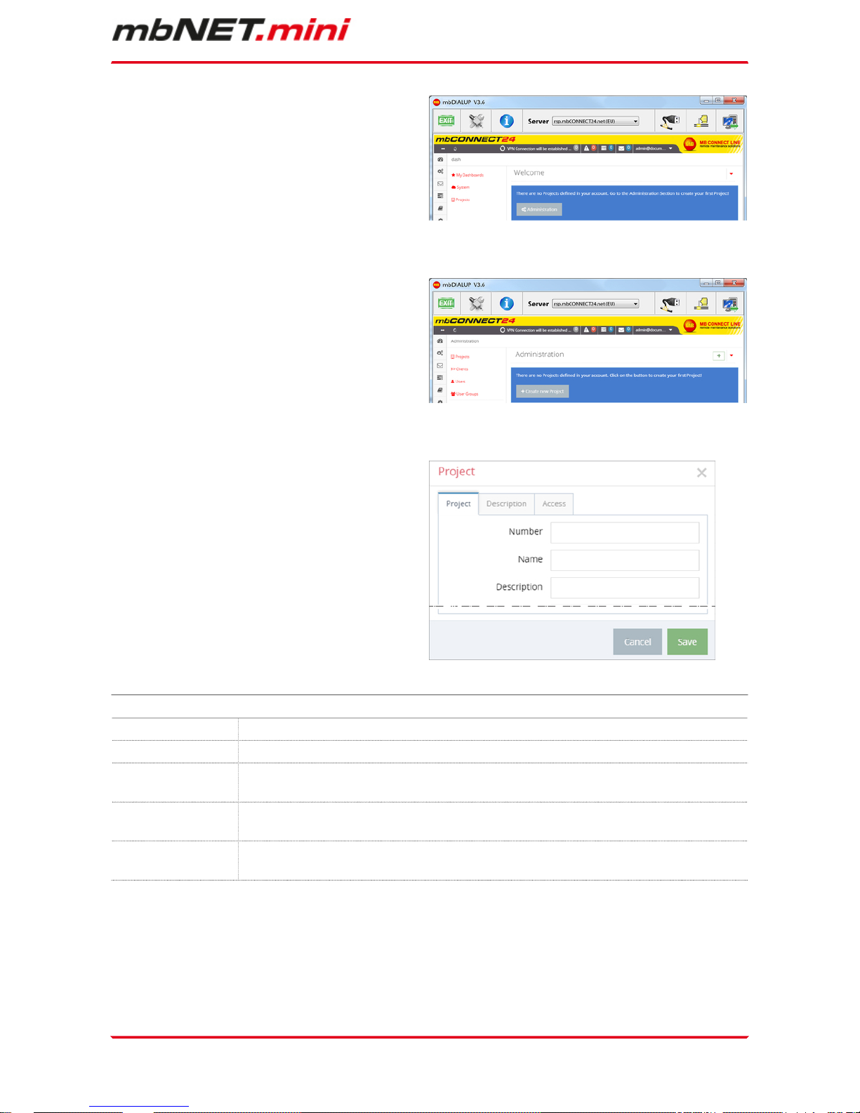
Click the "Administration" button under the Note:
"There are no projects defined in your account. Go
to the Administration Section to create your first
project!"
On the next window, click "+ Create new Project".
For the basic configuration, it is necessary to fill in
the following information:
•
Number
•
Name
•
Description
The tabs „Description“ and „Access“ are necessary
for the extended configuration
Term Description
Number Optional field - Input value = alphanumeric
Name Mandatory field - Input value = alphanumeric
Description Optional field - Input value = alphanumeric. The short description entered is dis-
played in the project overview.
Cancel By clicking on Cancel, the process is terminated. All entries / settings also in the other
tabs (Description, Access), will be lost.
Safe By clicking on Save, the process is finished. All entries / settings also in the other tabs
(Description, Access) are stored.
Page 22 of 90 | Version: 1.6.0 DR 03 (10.01.2017) - EN | 10.01.2017
10.1.3.3 Create a new device
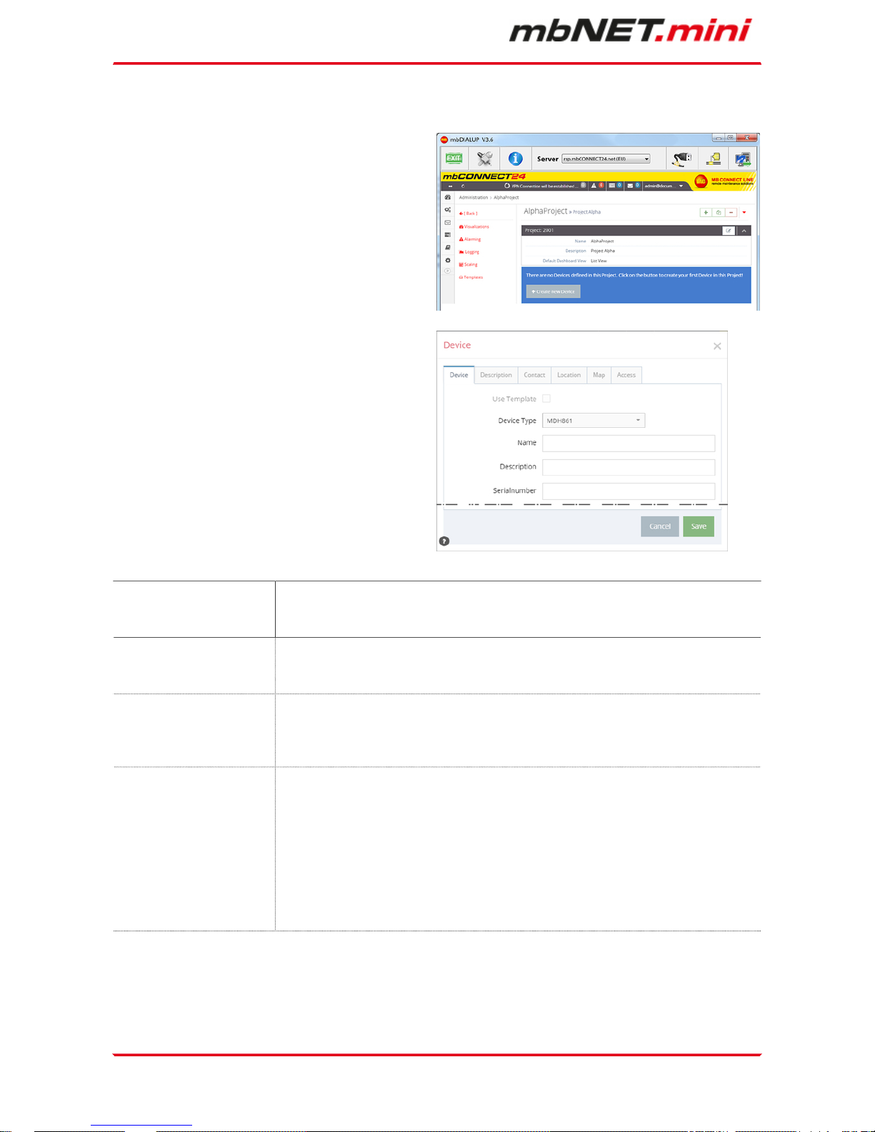
After you have defined a Project, it appears following announcement: : "There are no Devices defined
in this Project. Click on the button to create your first
Device in this Project!"
Click on the button „+ Create new Device“.
For the basic configuration, you only need the following data in the tab “Device”.
•
Device Type
•
Name
•
Description
•
Serial number
The tabs „Description“, „Contact“, „Location“, „Map“
and „Access“ are necessary for the extended configuration.
Type Selection field with all device types you can create in the portal.
The device type (eg Typ: MDH 834) can be found on the device nameplate, side
of the unit.
Name Mandatory field to enter a unique device name.
You can create your own name for your Device.
Following numbers and letters are allowed: 0 to 9, A to Z, a to z (avoid blanks).
Description Optional fieldto enter a briefdescription for the device.
The description can be freely selected and will be displayed later in the device
overview.
All numbers, words, blank spaces or additional characters are allowed.
Serial number a) Optional field: If you transfer the configuration to the device ("Download
to PC" or "Submit to device"), you can leave this field empty.
Once the device connects for the first time with the portal, the serial number is entered automatically.
b) Mandatory field: If the device at the first connection to the portal get its
configuration ("Prepare for Synchronization"), you must enter the serial
number of the device here.
The serial number (eg S/N: 211383405693) can be found on the device
nameplate, side of the unit.
Initial configuration | Page 23 of 90
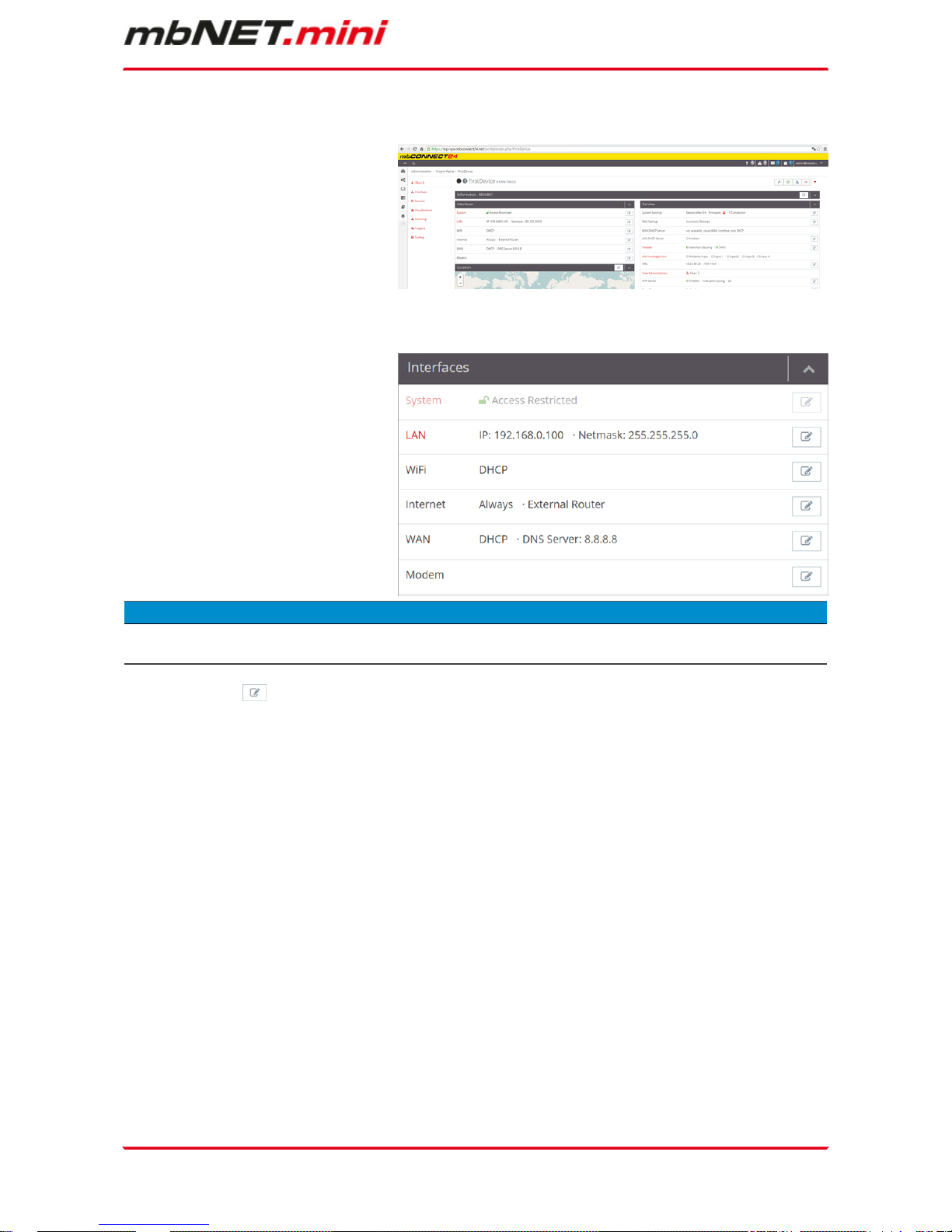
10.1.3.4 Create a configuration
After you have created a Device, the actual configuration menu appears.
For the basic configuration are solely the
following Interfaces necessary.
•
LAN
•
WiFi
•
Internet
•
WAN
•
Modem
ADVICE
According to the Type of your Device, the list of the interfaces could variegate.
Click the edit icon to make the settings on the submenus.
Page 24 of 90 | Version: 1.6.0 DR 03 (10.01.2017) - EN | 10.01.2017
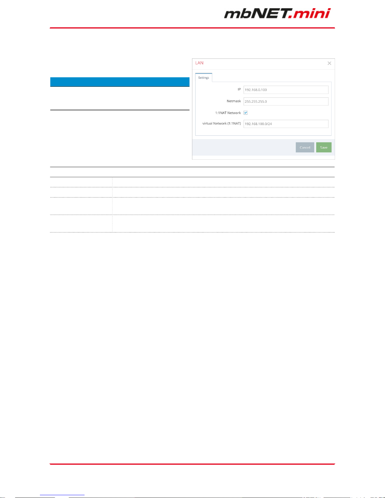
10.1.3.4.1 LAN Settings
Enter a free LAN IP address and the Netmask from
your system or machine network.
ADVICE
Notice, that the LAN and WAN IP-address
should use a different address range.
LAN Settings
IP Enter the IP-address of your Device
Netmask Enter the Subnetmask where your Device should be integrated.
1:1NAT Network Activate „1:1NAT Network“, if both contacts use the same Net address and want to
communicate with each other.
virtual Network
(1:1NAT)
Enter your address of your network (e.g. 192.168.100.0/24). Make sure you use the
CIDR spelling for the IP-address!
Initial configuration | Page 25 of 90
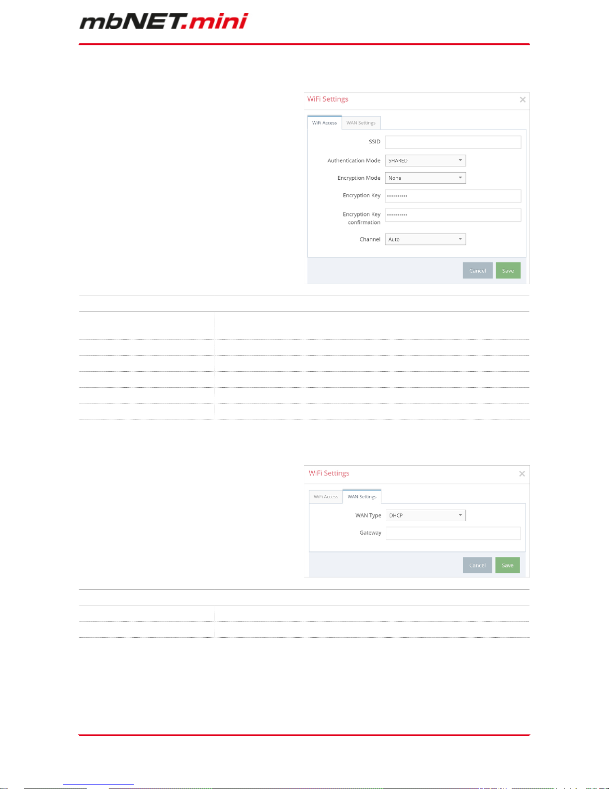
10.1.3.4.2 WiFi Settings
WiFi Access
If you want to configure a Device with a WLANmodule, enter the information of your Router or Access-point.
WiFi Access
SSID Mandatory field: Enter the name of the WiFi network to which the device
should connect.
Authentication Mode Selection field for the authentication mode.
Encryption Mode Selection field for the encryption mode.
Encryption Key Mandatory field: Enter the encryption key.
Encryption Key confirmation Mandatory field: Enter the encryption key again.
Channel Selection field for the WiFi channel.
WAN Settings - WAN Type: DHCP
Select this entry if you have a DHCP-server in your
network.
WAN-Einstellungen - WAN-Typ: DHCP
WAN Type Selection field for the WAN type (DHCP or Static IP).
Gateway Optional field: Enter the Gateway of your Network.
Page 26 of 90 | Version: 1.6.0 DR 03 (10.01.2017) - EN | 10.01.2017
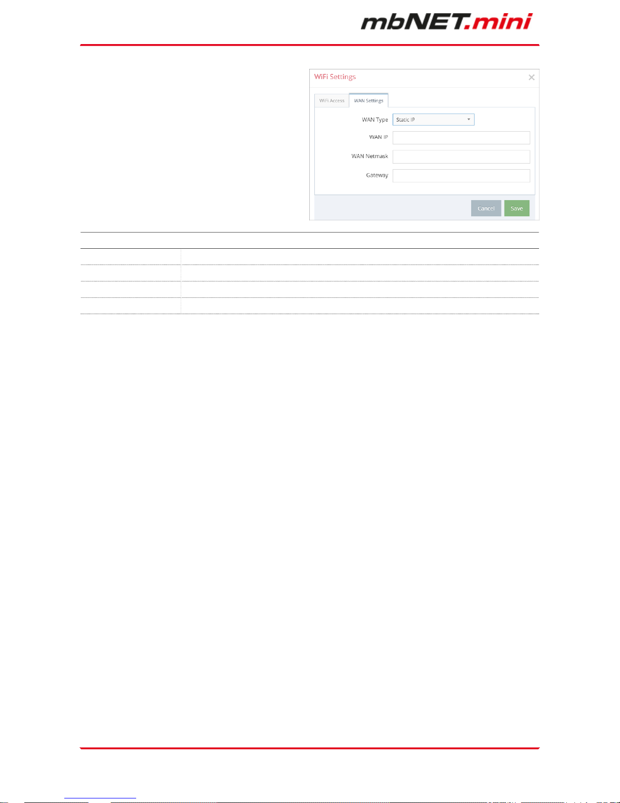
WAN Settings - WANType: Static IP
WAN Settings - WAN Type: Static IP
WAN Type Selection field for the WAN type (DHCP or Static IP)
WAN IP Mandatory field: Enter the IP-Address of the external Router
WAN Netmask Mandatory field: Enter the Subnet mask where your Device should be integrated.
Gateway Mandatory field: Enter the Gateway of the external Router.
Initial configuration | Page 27 of 90
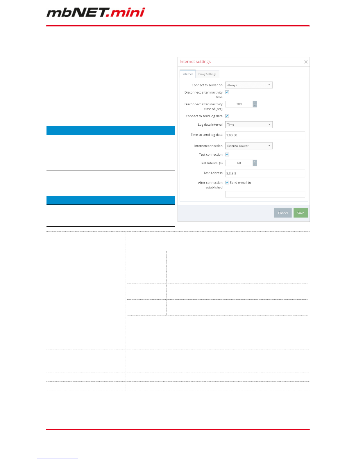
10.1.3.4.3 Internet Settings
You will need to specify:
•
when the device should be connected to the
portal
•
how the Internet connection should be established
•
which VPN port should be used (which of
the three ports is free was determined by
mbCHECK)
ADVICE
For the First Configuration it is advisable to select
„Always“ in the Tab „Connect to Server on“. Only in
this setting, the device automatically tries to establish a connection to the portal.
ADVICE
The Input-/ Selection-fields could variegate in addiction to the Device and the configuration.
Connect to server on Selection field for the time and condition how you want to connect the
Device with the Portal.
Dialout Button If you press the button „Dialout“ or “Function“ on your Device it
gets a connection to the Portal.
Always If the Device is powered on and operational, it will connect to
the portal.
SMS If you want to connect the Device with the portal you have to
send an SMS with the order to start a VPN-connection.
Input 1 Depending on the device type the connection can be controlled
by one or more digital inputs.
Disconnect after inactivity
time
Checkbox for activating automatic disconnection in case of inactivity.
Disconnect after inactivity
time of [sec]
After the Device has reached the preset time of inactivity (timeout) the
connection between Device and Server will disrupt.
Connect to send log data When the Device has a connection to the server, it will send log data in
a preset time of intervals. The disconnection takes place after the preset
timeout.
Log data interval Selection field for the interval of the data to be logged.
Time to send log data Input field for the transmission time of the log data.
 Loading...