

MB Companies MCD-WB Parts Manual
OPERATOR’S and PARTS MANUAL
Model MCD-WB
Walk-Behind Power Broom
M-B Companies, Inc.
1615 Wisconsin Ave.
P. O. Box 200
New Holstein, WI 53061-0200
(920) 898-1560 or 800-558-5800
FAX: (920) 898-4588
Publication: MCD-WB 031612
Copyright 2012


Table of conTenTs
INTRODUCTION
Operator’s Manual .................................................................................................3
Identication Numbers ...........................................................................................3
SAFETY
Safety Alerts ...........................................................................................................5
Safety Decals .........................................................................................................5
Operation Guidelines .............................................................................................5
Slope Operation .....................................................................................................6
Children..................................................................................................................7
Emissions ...............................................................................................................7
Service and Maintenance ......................................................................................7
ANSI B71.3-1995 Warnings ...................................................................................7
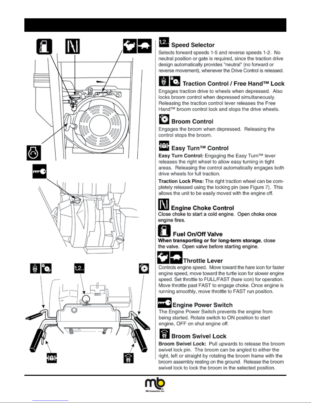
CONTROLS AND FEATURES .........................................................................................9
OPERATION
Checks Before Each Start-Up .............................................................................. 11
Starting Engine ....................................................................................................11
Operating Power Broom ......................................................................................12
Ground Speed Selector .......................................................................................12
Engine Speed ......................................................................................................12
Brush Angle Adjustment .......................................................................................12
Brush Height Adjustment .....................................................................................13
Easy Turn Freewheeling and Traction Drive Lock ...............................................13
OPTIONAL EQUIPMENT
Turf Caster Installation .........................................................................................15
Dirt Deector Installation ......................................................................................15
Debris Box Installation .........................................................................................15
ADJUSTMENTS AND SERVICE
Speed Selector Adjustment..................................................................................17
Broom Drive Tension ............................................................................................17
Traction Drive Tension .........................................................................................17
Easy Turn Cable Adjustment................................................................................18
Shear Pin Replacement .......................................................................................18
Belt Replacement.................................................................................................19
Brush Segment Replacement ..............................................................................20
Publication: MCD-WB 021512
M-B Companies, Inc. Copyright 2012
1

Table of conTenTs
MAINTENANCE
Maintenance Schedule ........................................................................................23
Lubrication ...........................................................................................................23
Checking Tire Pressure........................................................................................24
STORAGE
Temporary ............................................................................................................25
Long Term ............................................................................................................25
Starting After Long Term Storage .........................................................................25
TROUBLESHOOTING ...................................................................................................27
SERVICE PARTS ...........................................................................................................29
PARTS LISTS ................................................................................................................. 30
WARRANTY
DRAWINGS
2
Publication: MCD-WB 021512
M-B Companies, Inc. Copyright 2012

INTRODUCTION
OPERATOR’S MANUAL
You must read, understand and comply with all the safety and operating instructions in this manual before attempting to set-up and operate
your unit.
Failure to comply with the safety and operating instructions can result
in loss of machine control, serious personal injury to you and/or bystanders, and risk of equipment and property damage.
IDENTIFICATION NUMBERS
When contacting your authorized dealer for information, replacement
parts or service, you MUST have the model and serial number of your
broom head and drive unit.
The broom head serial number plate/decal can be found in the location
shown in Figure 1. Record the serial number in the space provided.
Broom Serial Number:
The drive unit (engine and drive wheels) serial number decal is located
on the inside front of the frame for drive unit S/Ns prior to 2014627501.
The broom head mounting frame must be disconnected from the drive
unit to gain access to the decal.
Beginning with drive unit S/N 2014627501, the serial number decal is
located on the outside rear of the bottom cover, between the handlebar
supports. Record the serial number in the space provided.
Drive Unit Serial Number:
Figure 1.
Publication: MCD-WB 122711
M-B Companies, Inc. Copyright 2011
3

This Page Intentionally Blank
4
Publication: MCD-WB 122711
M-B Companies, Inc. Copyright 2011

SAFETY
SAFETY ALERTS
Signal words and alert symbols notify of important safety precautions.
DANGER! Indicates a hazardous situation
which, if not avoided, will result in
serious injury or death.
WARNING! Indicates a hazardous situation
which, if not avoided, could result in
serious injury or death.
CAUTION! Indicates a hazardous situation or
unsafe practice which, if not avoided,
could result in minor or moderate
injury or property damage.
SAFETY DECALS
Although reading this manual and the safety instructions it contains
will provide you with the necessary basic knowledge to operate this
equipment safely and effectively, we have placed several safety labels
on the unit to remind you of this important information while you are
operating your unit.
All DANGER, WARNING, CAUTION, and instructional messages on
your unit should be carefully read and obeyed. Bodily injury can result
when these instructions are not followed. The information is for your
safety and it is important.
These labels will act as a constant visual reminder to you, and others
who may use the equipment, to follow the safety instructions necessary
for safe, effective operation.
If any of these labels are lost or damaged, replace them at once. See
you local dealer for replacements.
PRE-START GUIDELINES
• Install any covers or guards which may have been removed for ship-
ping purposes.
• Before starting equipment, walk around equipment, making a visual
inspection that all safety devices are properly installed and secured.
• Check that all hardware, fasteners, hydraulic ttings, etc. are in good
condition and properly fastened. Replace any fatigued or damaged
items with proper replacements.
• Personnel who are not required to be in the work area should be
kept away. Never start the equipment unless you are absolutely
certain that everyone in the area is clear of the machine and aware it
is being started.
• Follow the manufacturer’s recommended start-up procedure.
Publication: MCD-WB 111511
M-B Companies, Inc. Copyright 2011
OPERATION GUIDELINES
Read, understand and follow all instructions in the manual and on the
unit before starting.
• To avoid serious injury or death, do not modify equipment. Any
modications made to equipment can be dangerous and can void
equipment warranty.
• Never defeat a safety device to make a task easier.
• Always wear proper apparel when operating equipment; safety
glasses, face shield or goggles, ear protection, and dust mask. Tie
hair back. Never wear loose clothing or jewelry that could get caught
in moving parts.
• Never operate equipment with covers or guards removed. Rotating
parts can cause severe injury. Keep hands, feet, hair, jewelry and
clothing away from all moving parts.
• Only allow responsible adults who are familiar with the instructions,
to operate the unit (local regulations can restrict operator age).
• Clear the area of objects such as rocks, toys, wire, etc., which could
be picked up and thrown.
• Be aware of surroundings. Be sure the area is clear of other people,
bystanders or pets. Stop unit if anyone enters the area.
• Always look down and behind before and while traveling in reverse.
• Be aware of discharge direction and do not point discharge at any-
one. Do not point the discharge at glass enclosures, automobiles, or
windows.
5

SAFETY
• Always stand clear of the discharge area when operating this unit.
• Disengage all clutches and PTO’s before starting engine.
• Never leave a running machine unattended. Always disengage the
attachment and traction controls, lower the attachment, set the park
brake, stop the engine and remove the ignition key before leaving
the machine.
• Operate only in daylight or good articial light.
• Never carry passengers.
• Do not operate the unit while under the inuence of drugs, alcohol or
other medication.
• Watch for trafc when operating near or crossing roadways.
• Use extra care when loading or unloading the unit into a trailer or
truck.
• Keep in mind the operator is responsible for accidents occurring to
other people or property.
• Data indicates that operators, age 60 years and above, are involved
in a large percentage of power equipment-related injuries. These op-
erators should evaluate their ability to operate the unit safely enough
to protect themselves and others from injury.
• All operators should seek and obtain professional and practical
instruction.
• Protect eyes, face and head from objects that may be thrown from
unit. Wear appropriate hearing protection.
• Always wear substantial footwear and appropriate clothing. Wear
footwear that improves traction on slippery slopes. DO NOT wear
long scarves or loose clothing that could become entangled in mov-
ing parts.
• Abnormal Vibrations are a warning of trouble. Striking a foreign
object can damage unit. Stop unit and engine. Wait for all moving
parts to stop. Inspect unit and make any necessary repairs before
restart.
• Never place your hands or any part of your body or clothing inside or
near any moving part while unit is running.
• Stop engine before: refueling, cleaning, making adjustments or
removing the attachment assembly.
• Follow the drive unit manufacturer’s recommendations for wheel
weights or counter weights.
• Make any adjustments before operating unit.
• Do not touch parts which may be hot from operation. Allow such
parts to cool before attempting to service the unit.
• Before using, always visually check that hardware is present, intact
and secure. Replace worn or damaged parts.
• Never operate the machine with damaged guards, or without safety
protective devices in place.
• Original purchaser of this unit was instructed by the seller on safe
and proper operation. If unit is to be used by someone other than
original purchaser; loaned, rented or sold, ALWAYS provide this
manual and any needed safety training before operation.
• The Operator must understand the functions and parameters of all
controls and how to operate, as well as how to STOP in an Emer-
gency.
NOTE: All reference to left, right, front, or rear are given from the
operator position and facing forward.
SLOPE OPERATION
WARNING! Never operate on slopes greater than
17.6 percent (10°), which is a rise of
3-1/2 feet (106 cm) vertically in 20 feet
(607 cm) horizontally.
When operating on slopes use additional wheel weights or counterweights. See your dealer to determine
which weights are available and
appropriate for your unit.
Select slow ground speed before
driving onto slope. Travel UP and
DOWN the slope, never across the
face, use caution when changing
directions and DO NOT START OR
STOP ON SLOPE.
Slopes are a major factor related to loss-of-control and tipover accidents, which can result in severe injury or death. All slopes require
extra caution. If you cannot back up the slope or if you feel uneasy on
it, do not operate on it.
Do
• See your authorized dealer for recommendations counterweights to
improve stability.
• Travel up and down slopes, not across.
• Remove obstacles such as large rocks, tree limbs, etc.
• Watch for holes, ruts, or bumps. Uneven terrain could overturn the
unit. Snow can hide obstacles.
• Use slow speed. Tires may lose traction on slopes.
• Choose a low gear so that you will not have to stop or shift while on
the slope.
• Keep all movement on the slopes slow and gradual.
• Do not make sudden changes in speed or direction.
• Always keep unit in gear especially when traveling downhill.
Do Not
• Do not start or stop on a slope. If tires lose traction, disengage the
broom and proceed slowly straight down the slope.
• Do not turn on slopes unless necessary, and then, turn slowly and
gradually downhill, if possible.
• Do not operate near drop-offs, ditches, or embankments. The unit
could suddenly turn over if a wheel is over the edge of a cliff or ditch,
or if an edge caves in.
• Do not operate power broom on roof tops.
• Do not operate on wet surfaces. Reduced traction could cause slid-
ing.
• Do not shift to neutral and coast down hills.
6
Publication: MCD-WB 111511
M-B Companies, Inc. Copyright 2011

SAFETY
CHILDREN
Tragic accidents can occur if the operator is not alert to the presence of
children. Children are often attracted to the unit and the operating ac-
tivity. Never assume that children will remain where you last saw them.
• Keep children out of the area and under the watchful care of another
responsible adult.
• Be alert and turn unit off if children enter the area.
• Before and during reverse operation, look behind and down for small
children.
• Never allow children to operate the unit.
• Use extra care when approaching blind corners, shrubs, trees, or
other objects that may obscure vision.
EMISSIONS
• Engine exhaust from this product contains chemicals known, in
certain quantities, to cause cancer, birth defects, or other reproductive harm.
• Look for the relevant Emissions Durability Period and Air Index information on the engine emissions label.
SERVICE AND MAINTENANCE
• Use extra care in handling gasoline and other fuels. They are ammable and vapors are explosive.
a. Use only an approved container.
b. Never remove gas cap or add fuel with the engine running.
Allow engine to cool before refueling.
c. Do not smoke.
d. Never refuel the unit indoors.
• If fuel is spilled, do not attempt to start the engine but move the machine away from the area of spillage and avoid creating any source
of ignition until fuel vapors have dissipated.
• Replace all fuel tank caps and fuel container caps securely.
• Never ll containers inside a vehicle or on a truck bed with a plastic
bed liner. Always place containers on the ground away from your
vehicle before lling.
• Remove gas-powered equipment from the truck or trailer and refuel
it on the ground. If this is not possible, then refuel such equipment
on a trailer with a portable container, rather than from a gasoline
dispenser nozzle.
• Keep nozzle in contact with the rim of the fuel tank or container
opening at all times until fueling is complete.
• Do not use a nozzle lock-open device.
• If fuel is spilled on clothing, change clothing immediately.
• Maintain or replace safety and instruction labels as necessary.
• Never run a unit in an enclosed area.
• Keep nuts and bolts tight and keep equipment in good condition.
• Never tamper with safety devices. Check their proper operation
regularly and make necessary repairs if they are not functioning
properly.
• Keep unit free of debris build-up. Clean up oil or fuel spillage.
• Stop and inspect the equipment if you strike an object. Repair, if
necessary, before restarting.
• Never make adjustments or repairs with the engine running unless
specied otherwise in the engine manufacturer’s manual.
• Components are subject to wear, damage, and deterioration.
• Frequently check components and replace with manufacturer’s
recommended parts, when necessary.
• Check control operation frequently. Adjust and service as required.
• Use only factory authorized replacement parts when making repairs.
• Always comply with factory specications on all settings and adjustments.
• Only authorized service locations should be utilized for major service
and repair requirements.
• Never attempt to make major repairs on this unit unless you have
been properly trained. Improper service procedures can result in
hazardous operation, equipment damage and voiding of manufac-
turer’s warranty.
• Do not change engine governor settings or overspeed the engine.
Operating the engine at excessive speed can increase the hazard of
personal injury.
• Disengage broom and traction, stop the engine, and disconnect
the spark plug wire(s) before: performing service work or if the unit
vibrates abnormally.
• After striking an object, inspect the machine for damage and make
repairs before restarting and operating the equipment.
ANSI B71.3-1995 WARNINGS
Training
1. Read the operating and service instruction manual carefully.
Be thoroughly familiar with the controls and the proper use of
the equipment. Know how to stop the unit and disengage the
controls quickly.
2. Never allow children to operate the equipment.
3. Never allow adults to operate the equipment without proper
instruction.
4. Keep the area of operation clear of all persons, particularly small
children and pets.
5. Exercise caution to avoid slipping or falling especially when
operating in reverse.
Preparation
1. Thoroughly inspect the area where the equipment is to be used
and remove all doormats, sleds, boards, wires, and other foreign
objects.
2. Disengage all clutches and shift into neutral before starting
engine (motor).
3. Do not operate the equipment without wearing adequate outer
garments. Wear footwear that will improve footing on slippery
surfaces.
4. Handle fuel with care; it is highly ammable.
a. Use an approved fuel container.
b. Never add fuel to a running engine or hot engine.
c. Fill fuel tank outdoors with extreme care. Never ll fuel tank
indoors.
d. Replace fuel cap securely and wipe up spilled fuel.
5. Never attempt to make any adjustments while the engine (mo-
tor) is running (except when specically recommended by the
manufacturer).
6. Let engine (motor) and machine adjust to outdoor temperatures
before starting to clear snow.
7. Always wear safety glasses or eye shields during operation or
while performing an adjustment or repair to protect eye from
foreign objects that may be thrown from the machine.
Operation
1. Do not put hands or feet near or under rotating parts. Keep
clear of the discharge opening at all times.
2. Exercise extreme caution when operating on or crossing gravel
drives, walks, or roads. Stay alert for hidden hazards or trafc.
Publication: MCD-WB 111511
M-B Companies, Inc. Copyright 2011
7

SAFETY
3. After striking a foreign object, stop the engine (motor), remove
the wire from the spark plug, disconnect the cord on electric motors, thoroughly inspect the power broom for any damage, and
repair the damage before restarting and operating the power
broom.
4. If the unit should start to vibrate abnormally, stop the engine
(motor) and check immediately for the cause. Vibration is gen-
erally a warning of trouble.
5. Stop the engine (motor) whenever you leave the operating posi-
tion, before making any repairs, adjustments, or inspections.
6. When cleaning, repairing, or inspecting make certain the broom
and all moving parts have stopped. Disconnect the spark plug
wire and keep the wire away from the plug to prevent accidental
starting.
7. Do not run the engine indoors except for starting the engine or
for transporting the power broom in or out of the building. Open
the outside doors; exhaust fumes are dangerous.
8. Do not clear snow across the face of slopes. Exercise extreme
caution when changing direction on slopes. Do not attempt to
clear steep slopes.
9. Never operate the power broom without proper guards plates, or
other safety protective devises in place.
10. Never operate the power broom near glass enclosures, automo-
biles, window wells, drop-offs, and the like without proper adjustment of the discharge angle. Keep children and pets away.
11. Do not overload the machine capacity by attempting to clear
snow, sand or dirt at too fast a rate.
12. Never operate the machine at high transport speeds on slippery
surfaces. Look behind and use care when backing.
13. Never direct discharge at bystanders or allow anyone in front of
the unit.
14. Disengage power to the broom when power broom is transported or not in use.
15. Use only attachments and accessories approved by the manu-
facturer of the power broom (such as wheel weights, counterweights, cabs, and the like).
16. Never operate the power broom without good visibility or light.
Always be sure of your footing, and keep a rm hold on the
handles. Walk, never run.
Maintenance and Storage
1. Check shear bolts and other bolts at frequent intervals for
proper tightness to be sure the equipment is in safe working
condition.
2. Never store the machine with fuel in the fuel tank inside a building where ignition sources are present such as hot water and
spacer heaters, clothes dryers, and the like. Allow the engine to
cool before storing in any enclosure.
3. Always refer to the operator’s guide instructions for important
details if the power broom is to be stored for an extended
period.
4. Maintain or replace safety and instruction labels as necessary.
5. Run the machine a few minutes after moving snow to prevent
freeze-up of the broom assembly.
6. Always observe safe refueling and fuel handling practices when
refueling the unit after transportation or storage.
7. Always follow the engine manual instructions for storage
preparations before storing the unit for both short and long term
periods.
8. Always follow the engine manual instructions for proper start-up
procedures when returning the unit to service.
8
Publication: MCD-WB 111511
M-B Companies, Inc. Copyright 2011
controls and features
Publication: MCD-WB 070111
M-B Companies, Inc. Copyright 2011
9

This Page Intentionally Blank
10
Publication: MCD-WB 070111
M-B Companies, Inc. Copyright 2011
operation
CHECKS BEFORE EACH START-UP
1. Make sure all safety guards are in place and all nuts, bolts and
clips are secure.
2. Check the engine oil level. See your engine Owner’s Manual for
procedure and specications.
3. Check to make sure spark plug wire is attached and spark plug
is tightened securely. If necessary, torque spark plug to 15 ft.
lbs.
4. Check the fuel supply. Fill the tank no closer than 1/4 to 1/2 inch
of top of tank to provide space for expansion. See your engine
Owner’s Manual for fuel recommendations.
5. Check the casters to make sure they are set at the desired
height.
6. Check the Drive Control (B, Figure 2), and Broom Control (C)
for proper operation. If adjustment is required, see the Service
section for procedures.
7. Make sure that the broom is angled in the proper direction. See
the Service section for adjustment procedures and troubleshooting.
8. Check the Speed Selector (A, Figure 2) for smooth operation.
The control must move freely into each speed position gate and
remain in position when released. If the Speed Selector does
not move freely into all forward and reverse speed positions,
contact your local authorized dealer for assistance.
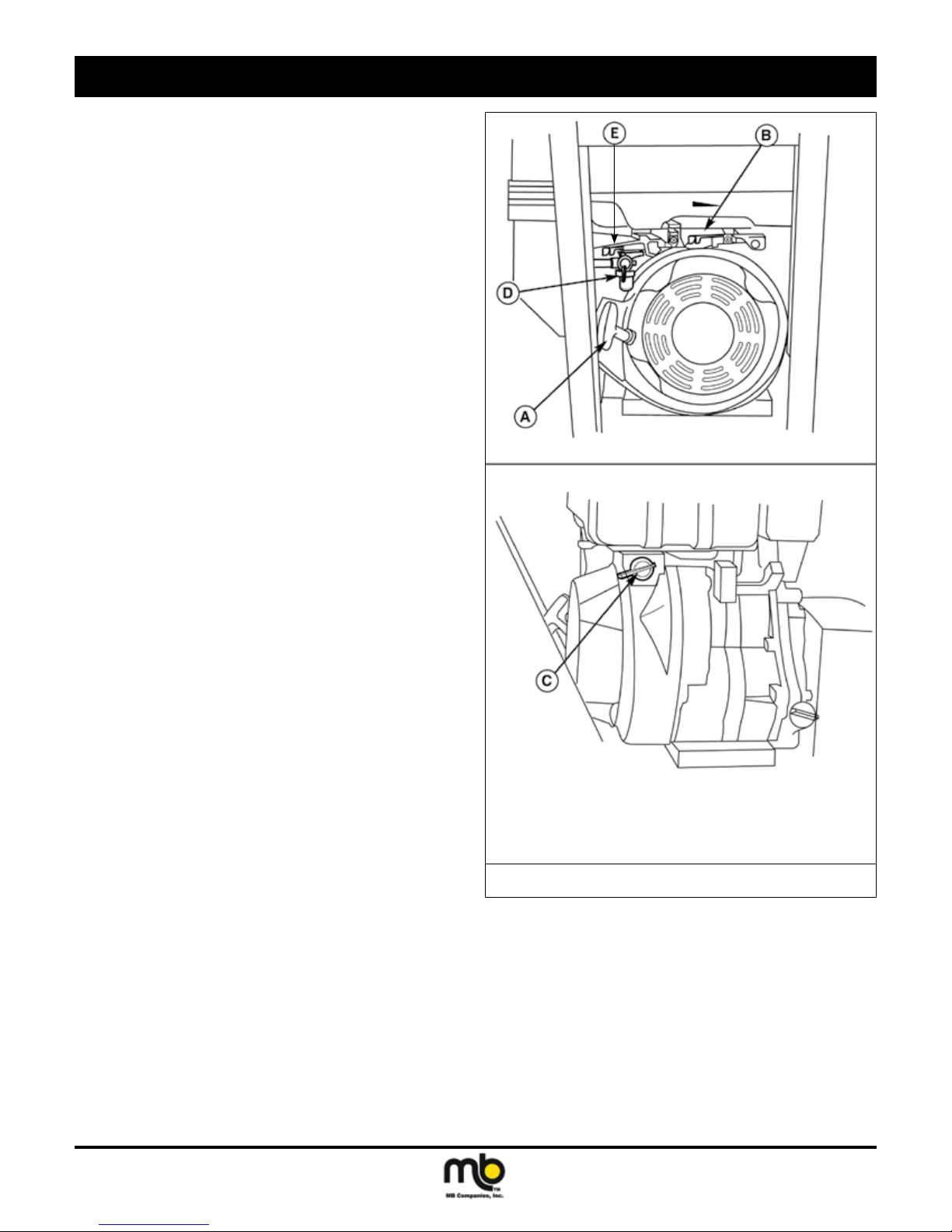
STARTING THE ENGINE
See Figure 1.
1. Turn the fuel valve (D) to the ON position.
2. Set Engine Power switch (C) to the ON position.
3. Move the Throttle Lever (B) fully to the FAST position.
4. Close the Choke Control (E) fully. (Do not choke a warm engine.)
5. Pull Starter Handle (A) rapidly to start the engine. Do not allow
the Starter Handle to snap back—let the starter rope rewind
slowly—while keeping a rm grip on the Starter Handle.
6. As the engine starts, slowly open Choke Control (E) and slide
Throttle Lever (B) towards the idle position. Allow engine to run
for a few minutes until it runs smoothly.
NOTE: Allow the engine to warm up at SLOW throttle for a few
minutes before operating the power broom at full speed. The
engine will not develop full power until it reaches operating
temperature. After warming up, always operate at full throttle.
WARNING! For your safety, operation on slopes
should be in an up and down direction only. If it becomes necessary
to move across the face of a slope,
use caution and do not engage the
broom. Be very careful when changing direction on a slope.
Proper footwear is recommended for
the operator to help prevent slipping.
Never attempt to operate on excessively steep slopes. The maximum
slope for any operation is 17.7% (10º).
A. Starter Handle D. Fuel Valve
B. Throttle Lever E. Choke Control
C. Engine Power Switch
Figure 1. Engine Controls
WARNING! Gasoline is highly ammable and
must be handled with care. Never ll
the tank when the engine is hot or
running. Always move outdoors to
ll the tank. Keep power broom and
gasoline away from open ame or
spark.
Publication: MCD-WB 122111
M-B Companies, Inc. Copyright 2011
11
operation
OPERATING THE POWER BROOM
WARNING! Always engage ground drive (trac-
tion control) before engaging broom
drive.
Always release the broom drive
before disengaging ground drive or
broom contact may push unit backwards.
1. Set the Speed Selector to the desired forward speed.
2. Fully press and hold the Traction & Free-Hand™ Control lever
(B, Figure 2) on the left-hand grip to engage the traction drive
and begin moving the power broom. To disengage the traction
drive, completely release the lever.
3. Fully press and hold the Broom Engage Control (C, Figure 2)
on the right-hand grip to begin broom rotation. Releasing the
Broom Engage Control will disengage the broom —unless the
Free-Hand™ Control has been activated (See step 4 below).
WARNING! When BOTH levers are depressed,
the FreeHand™ Control is activated.
This allows Brush Engage Control
to be released — THE BRUSH ROTATION WILL CONTINUE — until the
FreeHand™ Control is released.
ENGINE SPEED
Broom speed is adjusted by engine rpm. Adjust broom speed as
needed.
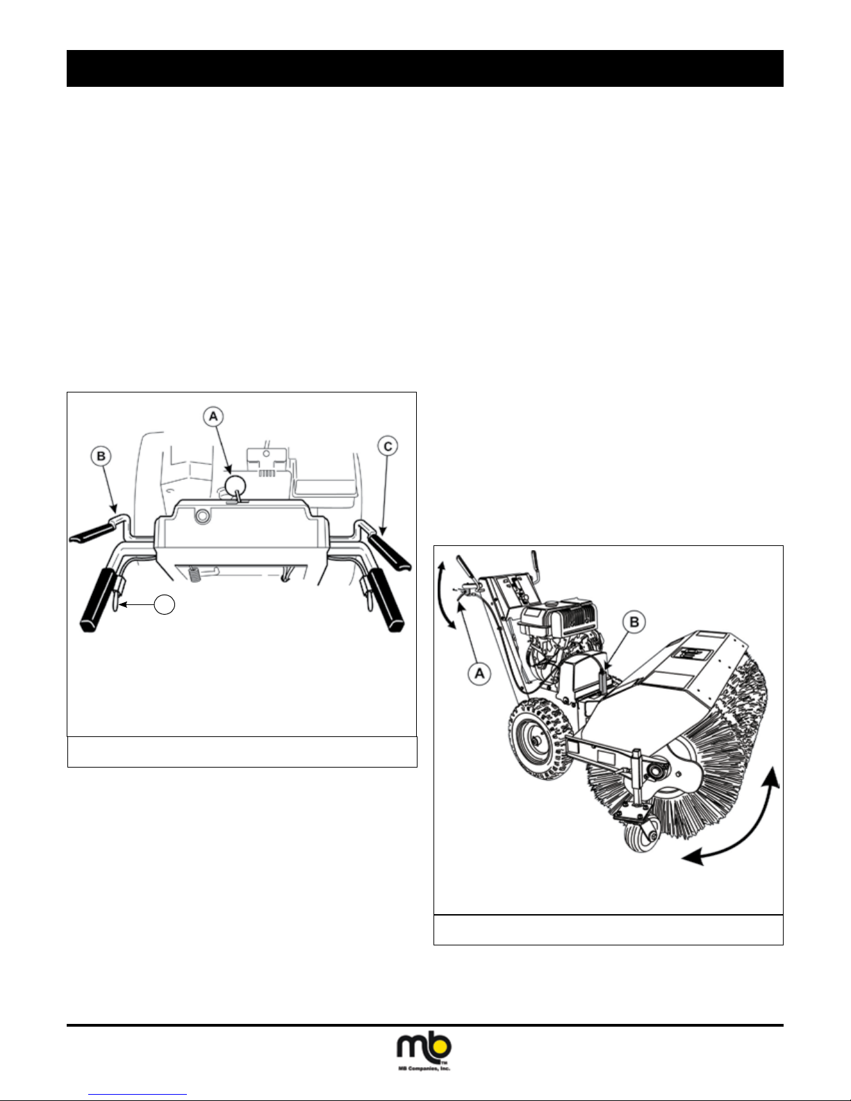
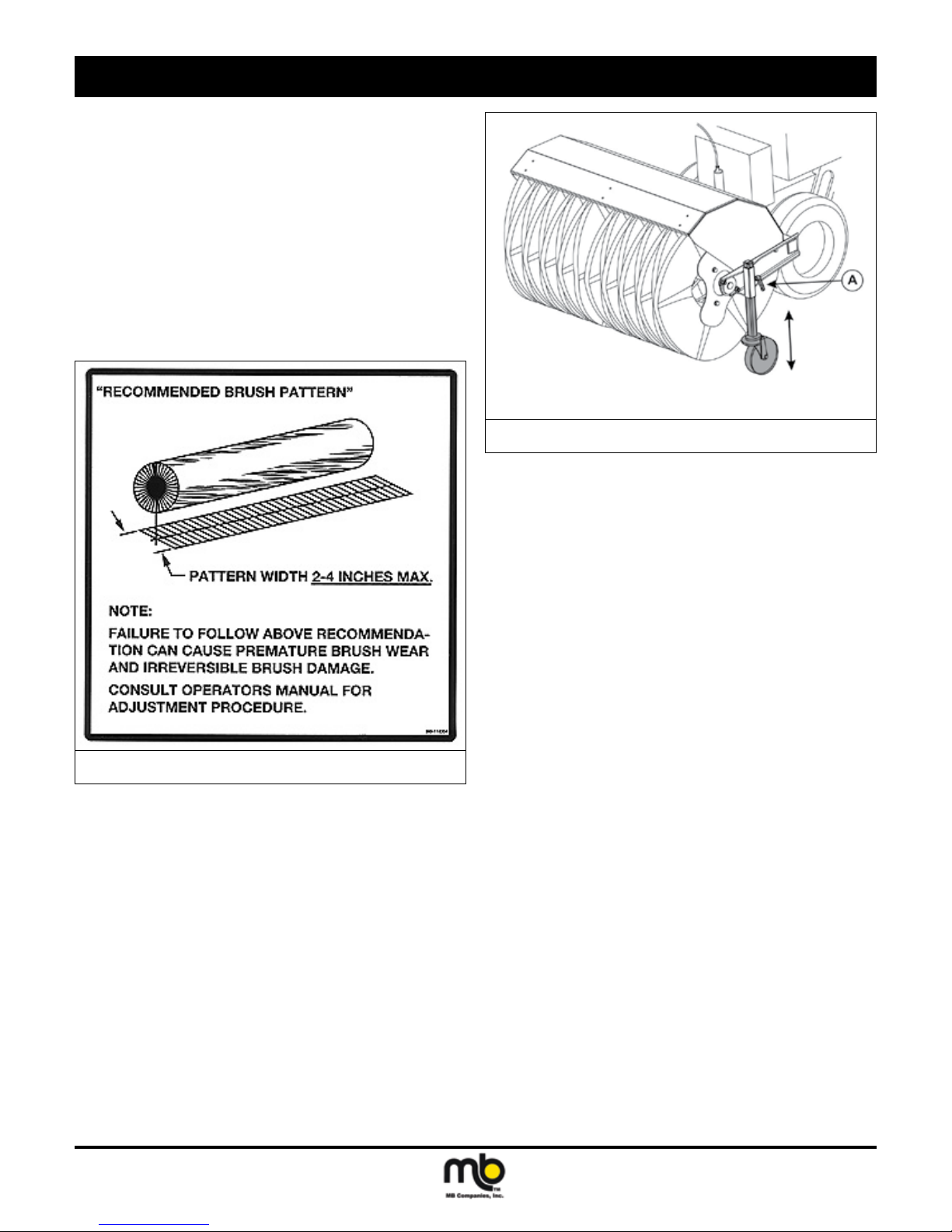
BRUSH ANGLE ADJUSTMENT
To change the angle of the brush:
1. Pull upwards on the Brush Lock Swivel Lock handle (A,
Figure 3) and hold. This will release the brush swivel lock pin
(B).
2. With the brush assembly resting on the ground, rotate the brush
frame to the right or left.
3. When the brush is in the proper position, release the brush lock
swivel lock handle. The brush assembly will be locked in the
selected position.
NOTE: The brush can be positioned to either 30° to the right or left
or straight ahead.
CAUTION! If brush height is set too low, brush
can drive machine rearward when attachment clutch is engaged. Engage
brush slowly with brush set at proper
height.
D
A. Speed Selector
B. Traction and Free-Hand™ Control
C. Broom Engage Control
D. Easy Turn Lever
Figure 2. Controls (from operator’s position)
4. When BOTH levers are depressed, the Free-Hand™ Control is
activated. This allows Broom Engage Control to be released —
BROOM ROTATION WILL CONTINUE — until the Free-Hand™
Control is released.
5. Select forward or reverse speeds as needed using the Speed
Selector (A, Figure 2). Release both control levers before
changing drive speeds.
GROUND SPEED SELECTOR
Use the Speed Selector (A, Figure 2) to control the drive speed of the
broom. There are ve forward speeds and two reverse speeds.
To change speeds, release both control levers (B, Figure 2), then move
the Speed Selector to the desired setting. Fully depress the control
levers to resume.
A. Brush Swivel Lock Handle
B. Swivel Lock Pin
Figure 3. Brush Swivel Controls
12
Publication: MCD-WB 122111
M-B Companies, Inc. Copyright 2011
operation
BRUSH HEIGHT ADJUSTMENT
For hard surfaces, adjust the caster wheels so that brush just touches
surface. The brush works best with the brush properly leveled. To
adjust the brush height:
1. Move the brush to a dusty, at surface. Leave the engine run-
ning.
2. Start the brush at a slow speed. Run the brush in a stationary
position for 30 seconds.
3. Lift the brush head assembly off the ground and reverse the unit
to move it away from the swept area.
4. Stop engine and allow all moving parts to stop.
5. Check the width of the swept area. The brush pattern should be
2-3 inches wide, running the length of the brush. (See Figure 4)
A. Caster Wheel Lock Lever
Figure 5. Pattern Adjustment
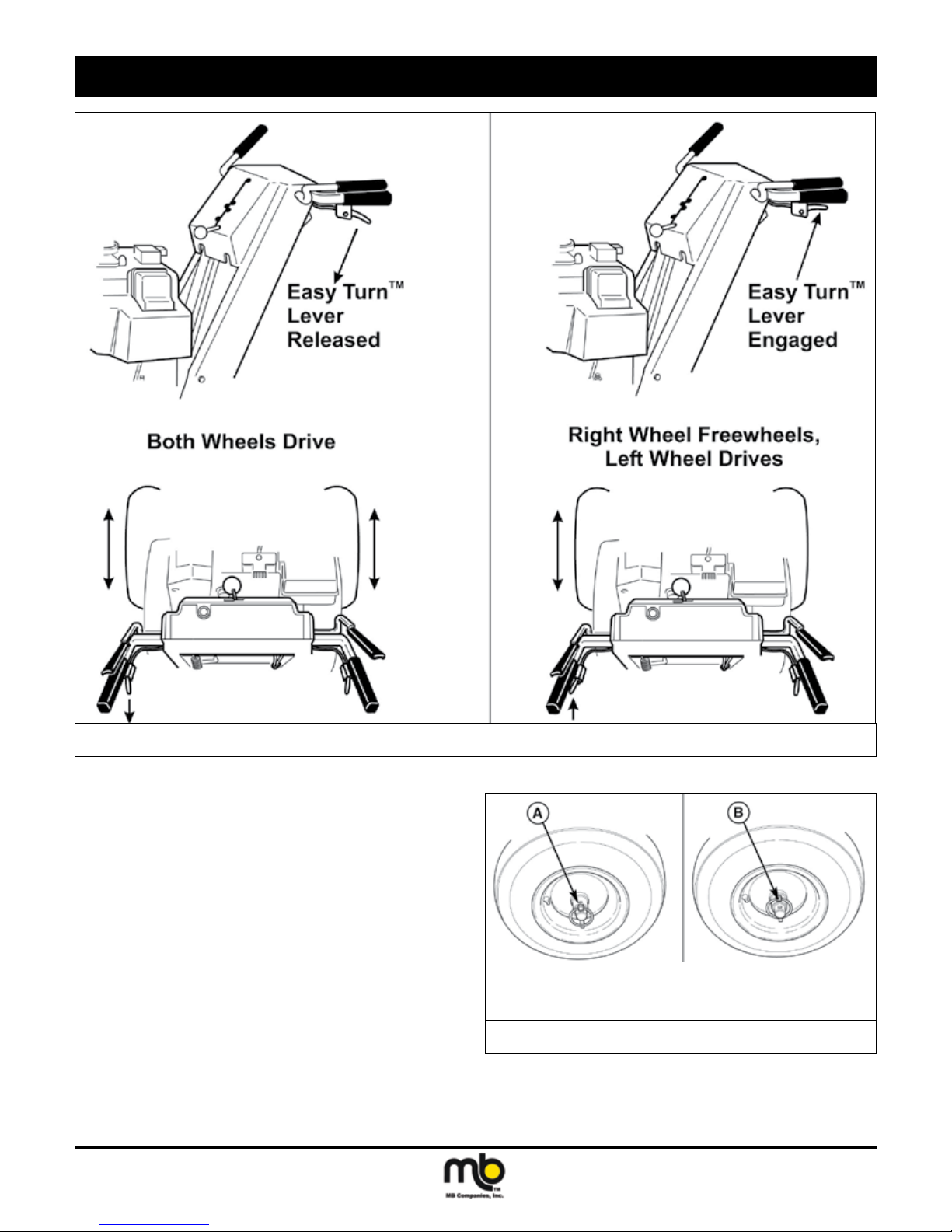
EASY TURN™ FREEWHEELING AND TRACTION DRIVE LOCK
Normal Operation
For easy turning when using the power broom, squeeze the Easy
Turn™ lever (Figure 6). Engaging the Easy Turn™ lever releases the
right traction wheel but allows the left wheel to continue driving. Re-
leasing the Easy Turn™ lever automatically engages both drive wheels
for full traction.
NOTE: The Easy Turn™ lever will be more difcult to activate under
a heavy load. Activate the lever before beginning a turn.
Figure 4. Brush Sweeping Pattern
6. To adjust:
a. Loosen the caster wheel lock lever. (See A, Figure 5)
b. Raise or lower the caster wheel as needed.
c. Tighten the caster wheel lock lever.
NOTE: If using the power broom for turf applications, less ground
contact is required.
Publication: MCD-WB 122111
M-B Companies, Inc. Copyright 2011
13
operation
Figure 6. Traction Drive Lock
When Pushing the Broom
For easy turning when pushing the power broom, disengage the right
wheel using the traction lock pin (See Figure 7).
1. Turn the unit off, remove the engine key, and disconnect the
spark plug wire.
2. To DISENGAGE the traction drive lock, insert the Traction Lock
Pin through the outer hole in the right axle. The unit can now be
pushed with minimal resistance.
3. To ENGAGE the traction drive lock, align the hole in the hub
with the inner hole in the axle, and install the Traction Lock Pin.
NOTE: Be sure both wheels are locked (locking pin in inner hole)
when clearing snow.
14
A. Pin in Outer Hole (Freewheel)
B. Pin in Inner Hole (Drive)
Figure 7. Traction Lock Pin - RH Wheel
Publication: MCD-WB 122111
M-B Companies, Inc. Copyright 2011
OPTIONAL EQUIPMENT
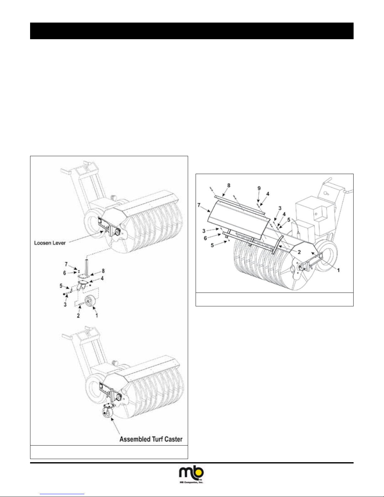
TURF CASTER INSTALLATION
The optional turf casters replace the standard broom caster wheels.
These casters provide greater otation when using the broom in turf
grooming applications.
See Figure 1.
1. Raise and support the broom head assembly about 2”off the
ground.
2. Loosen the standard caster assembly by loosening the locking
lever.
3. Remove the original caster wheel and caster mounting tube.
4. Attach caster wheel (1) to the caster fork swivel plate (4) using
bolt (3), bushing (2) and nut.
NOTE: Make sure to install the bushing into caster wheel before at-
taching caster wheel to the caster fork swivel plate.
5. Attach the caster forks (4) onto the caster mounting bracket (8)
using the carriage bolts (5), washer (6) and nuts (7).
6. Slide the turf caster wheel assembly into the mounting bracket
from underneath and secure in place with the locking lever.
7. Repeat Steps 2 - 6 for the other side of the broom.
DIRT DEFLECTOR INSTALLATION
See Figure 2.
1. Position deector straps (2) over broom hood (1) and secure
each strap with one bolt (3) washer (4) and nut (5) in the top
hole of the strap and broom hood.
2. Attach strap support (6) to each deector strap. Position the
support strap at the lower edge of the deector strap and secure
with one bolt (3) and nut (5) in each support strap.
3. Position the deector (7) and upper support strap (8) over the
broom hood and deector strap assembly. Secure the deector through the second hole at the top of the deector strap and
broom hood using one bolt (9), washer and nut (5).
Figure 1. Turf Caster Assembly
Publication: MCD-WB 070111
M-B Companies, Inc. Copyright 2011
Figure 2. Dirt Deector Installation
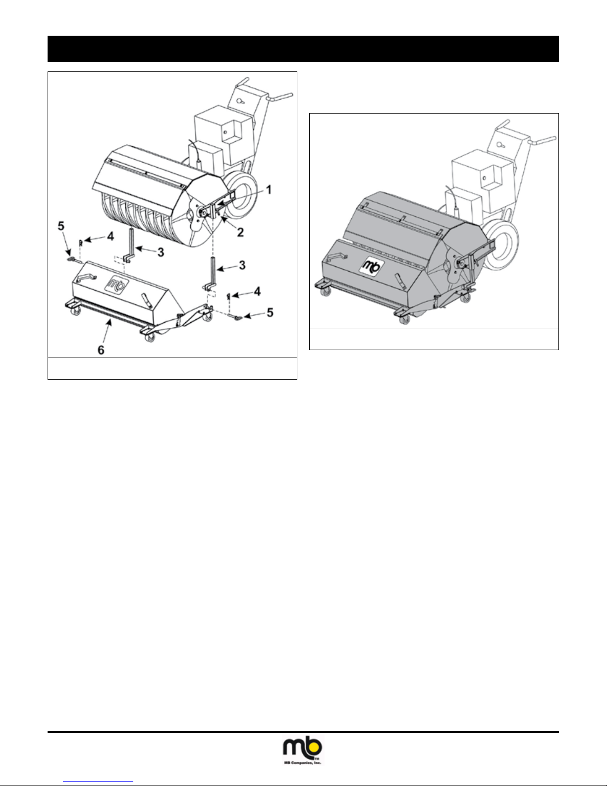
DEBRIS BOX INSTALLATION
See Figure 3.
1. Install optional Dirt Deector.
2. Raise and support the broom head assembly about 2”off the
ground. Loosen the standard caster assembly by loosening the
locking lever (2) and remove the caster assemblies.
NOTE: Save the standard casters for future use.
3. Position the debris box assembly (6) in-front of the power
broom.
4. Remove hitch pin (5), releasing debris box mounting tubes (3).
5. Raise the power broom upwards and insert the mounting tubes
(3) through the mounting brackets (1) on the broom frame.
6. Position the debris box assembly under the broom assembly
and lower the broom assembly onto the debris box mounting
brackets.
7. Insert hitch pin (5) to secure the broom assembly to the debris
box. Install hairpin cotter pin (4) to secure the hitch pin.
15
OPTIONAL EQUIPMENT
8. The nal assembly is shown in Figure 4.
9. Adjust the broom height to according to the Brush Height Adjustment procedure within the OPERATION section.
Figure 3. Debris Box Installation
Figure 4. Debris Box Installed on Power Broom
16
Publication: MCD-WB 070111
M-B Companies, Inc. Copyright 2011
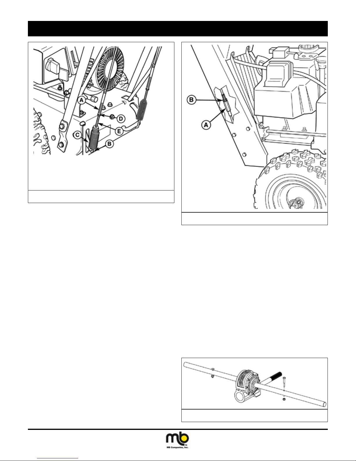
adjustments and service
SPEED SELECTOR ADJUSTMENT
See Figure 1.
1. Loosen the two nuts (C).
2. Place the shift lever in 5th gear.
3. Push the lower rod into the housing and tighten the two nuts (C).
Do not lift up or down on rods while tightening. Make sure the
shoulders of the carriage bolts (B) are in the slots.
4. Always check traction drive tension and broom drive tension
after adjusting speed selector.
8. If drive linkage is properly adjusted, broom drive belt tension
may require adjustment. See “Belt Adjustment” in this section of
the manual.
A. Adjusting Flats D. Nut
B. Spring Hook E. Adjustment Screw
C. Lever
A. Shift Rod B. Carriage Bolts C. Nuts
Figure 1. Speed Selector Linkage
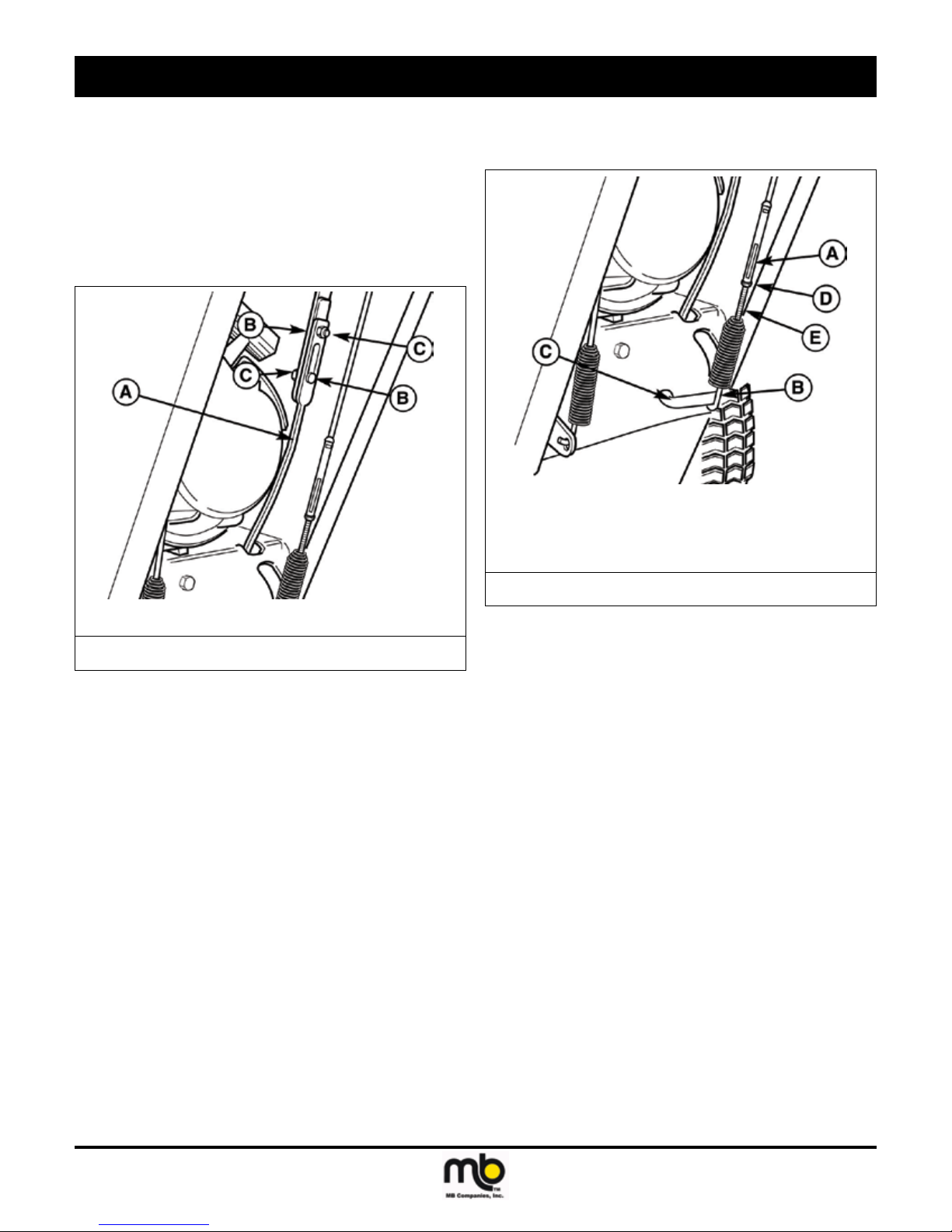
BROOM DRIVE TENSION
WARNING! Do not over-tighten, as this may lift
the lever and cause broom drive to
be engaged without depressing the
Broom Control.
See Figure 2.
1. With the drive lever released, the hook (B) should barely touch
the lever (C) without raising it. There can be a maximum 1/32”
clearance as shown.
NOTE: The adjustment screw is a phillips screw and the head can
be held or turned by inserting a screwdriver through the
spring.
2. To adjust, loosen nut (D) by holding the adjusting ats (A) and
turning nut (D). Turn adjustment ats and hold screw.
3. Hold adjusting ats (A) and tighten nut (D).
4. Start unit and check broom. Broom must not be engaged un-
less Broom Control is depressed.
5. With engine running, fully depress Broom Control, the broom
should engage and run normally.
6. Release Broom Control. Broom must stop within 5 seconds.
7. If broom does not operate properly, stop engine and recheck
drive linkage adjustments.
Figure 2. Broom Drive Adjustment
TRACTION DRIVE TENSION
Initial Adjustment
See Figure 3.
1. Lift the bellcrank arm (C) up as far as it will go.
2. While holding the bell crank arm (C) up, adjust the cable until all
the slack is removed.
3. Back the adjustment screw (E) out 7-8 turns. Tighten nut (D).
4. Start engine and check that the system disengages when the
control is released.
WARNING! WARNING Do not over-tighten, as
this may cause traction drive to engage without depressing the traction
drive control (bellcrank arm must
remain in down position).
Verify that the cables are not over-
tightened: With speed selector in
position 1 and traction drive control
fully released, push broom forward.
The unit should move forward freely.
If unit does not move forward freely,
the cable has been over-tightened.
To remedy, loosen tension on clutch
cable slightly, and recheck.
Publication: MCD-WB 120511
M-B Companies, Inc. Copyright 2011
17
adjustments and service
A. Adjusting Flats D. Nut
B. Spring Hook E. Adjustment Screw
C. Bellcrank Arm
Figure 3. Traction Drive Adjustment
Run-In Adjustment
1. After 5 hours of use, check for proper adjustment. Readjust
clutch cable if necessary by increasing tension on cable. A
small amount of bellcrank arm movement is permissible if unit
passes operating checks described in the WARNING above.
EASY TURN™ CABLE ADJUSTMENT
See Figure 4.
If the Easy Turn™ cable has stretched, the gears (clutches) will not
disengage when the control lever is activated. Adjust the cable using
the following procedure.
1. Turn the engine off and disconnect the spark plug wire.
2. Loosen the jam nut (B).
3. Turn the adjustment nut (A) to lengthen or shorten the cable.
The cable should be tightened just until all slack is removed
from the lever, however it must not engage the Easy Turn™
release without depressing the control lever.
4. Tighten the jam nut against the adjustment nut.
A. Adjustment Nut
B. Jam Nut
Figure 4. Easy Turn Cable Adjustment
SHEAR PIN REPLACEMENT
DANGER! Do not go near the broom when
the engine is running. Do not run
the engine with any cover or guard
removed.
Under most circumstances, if the broom strikes an object which could
cause damage to the unit, the shear pin(s) will break. (This protects the
gear box and other parts from damage.) The shear pins are located on
the broom shaft.
See Figure 5.
To replace the shear pins:
1. Tap out the broken pin(s) with a pin punch.
IMPORTANT! Do NOT replace shear pins with anything other than
the correct grade replacement shear pin. (Use of bolts,
screws or a harder shear pin will lead to damaged
equipment.
2. Install new shear pin(s) and secure with nut.
18
Figure 5. Shear Pin Replacement
Publication: MCD-WB 120511
M-B Companies, Inc. Copyright 2011
adjustments and service
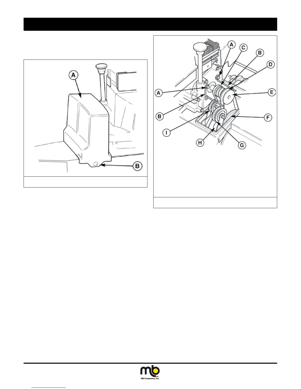
BELT REPLACEMENT
1. Turn off the engine, remove the spark plug wire, and wait for
all moving parts to stop. Loosen the two screws (B, Figure 6)
securing the belt cover.
A. Belt Cover
B. Screws
Figure 6. Belt Cover
2. Tilt the cover forward and work it off the power broom.
3. Move the belt guides (B, Figure 7) by loosening the two capscrews (A).
4. Remove the broom drive belt as follows:
a. Slip the broom drive belt (D, Figure 7) from the idler pulley by
pushing it away from the pulley and then toward the rear.
b. Remove the belt from the engine pulley.
c. Remove six capscrews from bottom cover to power broom
frame. Loosen nuts (A, Figure 8) on each side to release
broom pulley belt stops (B). Move belt stops and remove
belt from pulley (C).
NOTE: Make sure to rmly support the broom assembly.
d. Remove the four bolts that hold the broom head on and
remove broom head assembly.
e. Remove broom drive belt.
f. For more clearance to remove the belt, engage the traction
drive lever.
5. Remove the traction drive belt as follows:
a. Pull the idler pulley (I, Figure 7) away from the belt and slip
the belt from the pulley.
b. Slip the belt off the traction pulley and then the engine pulley.
The arm for the front idler pulley (G, Figure 7) may have to
be pivoted to provide clearance for removing the belt from
the traction pulley.
c. Pull the belt out between the broom pulley (F, Figure 7) and
traction pulley.
A. Capscrews F. Broom Pulley
B. Belt Guides G. Idler Pulley, Broom
C. Traction Drive Belt H. Traction Pulley
D. Broom Drive Belt I. Idler Pulley, Traction
E. Engine Pulley
Figure 7. Belts and Pulleys
6. Reverse the procedure to install the belts. Be sure there are no
twists and the belts are properly seated in the grooves. Adjust
the belt stops so there is 1/8” (3mm) clearance between belt and
stop. The pattern for both belts is shown in Figure 9. Slide the
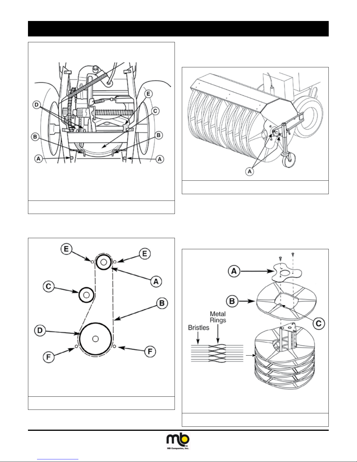
right axle left fully before tightening the set collar (E, Figure 8).
7. Check the traction drive tension and broom drive tension.
Follow the procedures under BROOM/TRACTION DRIVE TENSION.
8. Make sure the broom stops when the broom drive lever is
released. Make sure traction drive stops when the traction drive
lever is released. If not, check the drive tension. If a problem
exists, see your dealer.
Publication: MCD-WB 120511
M-B Companies, Inc. Copyright 2011
19
adjustments and service
Shown with bottom cover removed for clarity.
DO NOT operate broom with cover removed!
A. Nuts D. Gear Assembly Bolts
B. Belt Stops E. Set Collar
C. Broom Pulley
Figure 8. Broom Pulley Belt Stops
BRUSH SEGMENT REPLACEMENT
1. Remove bolts from broom bearings at both ends of the support
shaft (A, Figure 10).
A. Attachment Bolts
Figure 10. Brush Removal
2. Loosen bearing setscrews and slide bearings inwards toward
the center of broom.
3. Manually move power unit backwards away from the brush assembly.
IMPORTANT! Support splined drive shaft to prevent damage.
4. Stand broom assembly on one end. (See Figure 11)
A. Engine Pulley D. Driven Pulley
B. Drive Belt E. Engine Belt Stops
C. Idler Pulley F. Broom Pulley Belt Stops
Figure 9. Belt Pattern (viewed from front)
20
A. End Plate C. Engagement Fingers
B. Brush Segment
Figure 11. Brush Assembly
Publication: MCD-WB 120511
M-B Companies, Inc. Copyright 2011
 Loading...