

Page 1
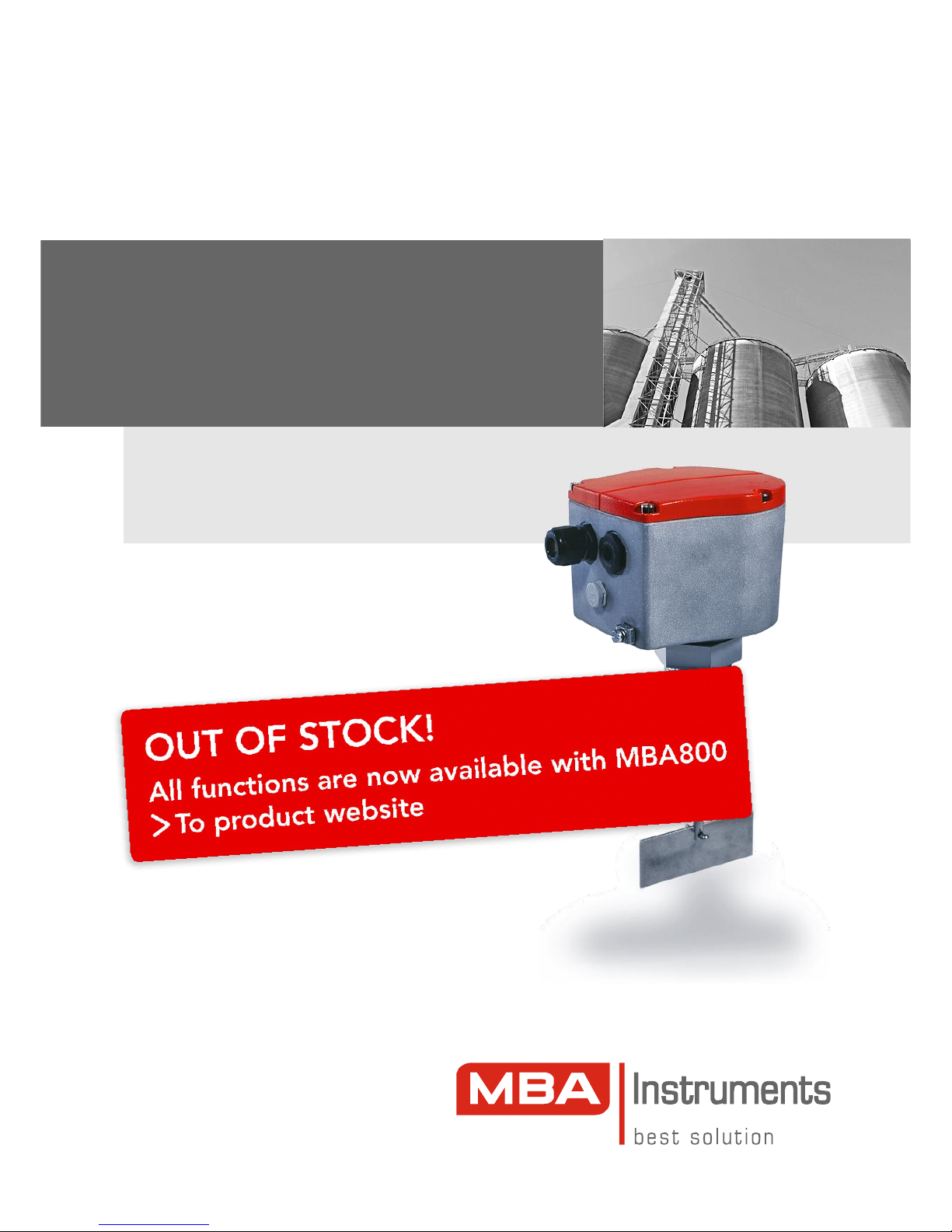
Operating instruction
MBA200
Rotating Bin-Level Indicator
Installation
Operation
Maintenance
Page 2
Bin-level Indicator MBA200
Document information
Document ID
Title: Operating Instructions MBA200
Order No.: 8011417
Version: 2.2
Stand: 2013-11
Subject
Product name: MBA200
Hardware: all versions
Manufacturer
MBA Instruments GmbH
Friedrich-List-Str. 5 · 25451 Quickborn · Germany
© MBA Instruments GmbH Germany. All rights reserved.
Explanation of warning symbols
Hazard (general)
Hazard by voltage
Hazard in explosion-hazardous locations
Hazard by high temperature or hot surface
Warning levels
CAUTION
Hazard or unsafe practice which could result in personal
injury or property damage.
WARNING
Risk or hazardous situation which could result in severe
personal injury or death.
Explanation of information symbols
Technical risk for this device or its function (general)
Technical risk for this device by voltage
or other electrical hazards
Supplementary information
Nice to know
Contents
1 Product overview . . . . . . . . . . . . . . . . . . . . . . . . . . . . . . .3
2 Product description . . . . . . . . . . . . . . . . . . . . . . . . . . . . .4
2.1 Unit components . . . . . . . . . . . . . . . . . . . . . . . . . . . . . . . . .4
2.2 Principle of operation . . . . . . . . . . . . . . . . . . . . . . . . . . . . . .4
2.3 Optional equipment . . . . . . . . . . . . . . . . . . . . . . . . . . . . . . .4
2.4 Appropriate use . . . . . . . . . . . . . . . . . . . . . . . . . . . . . . . . . .4
2.5 Responsibility of the user . . . . . . . . . . . . . . . . . . . . . . . . . . .4
3 Installation . . . . . . . . . . . . . . . . . . . . . . . . . . . . . . . . . . . . .5
3.1 Protective roof / deflector . . . . . . . . . . . . . . . . . . . . . . . . . . .5
3.2 Assembly (if required) . . . . . . . . . . . . . . . . . . . . . . . . . . . . .5
3.3 Installation . . . . . . . . . . . . . . . . . . . . . . . . . . . . . . . . . . . . . .6
3.3.1 Operational conditions . . . . . . . . . . . . . . . . . . . . . . . . . . .6
3.3.2 Installation position . . . . . . . . . . . . . . . . . . . . . . . . . . . . .6
3.3.3 Attachment . . . . . . . . . . . . . . . . . . . . . . . . . . . . . . . . . . . .6
3.3.4 Temperatures of the distance tube . . . . . . . . . . . . . . . . .7
3.4 Electrical connection . . . . . . . . . . . . . . . . . . . . . . . . . . . . . .7
3.4.1 Important safety notes . . . . . . . . . . . . . . . . . . . . . . . . . .7
3.4.2 Safe electrical installation . . . . . . . . . . . . . . . . . . . . . . .7
3.4.3 Protection against explosion . . . . . . . . . . . . . . . . . . . . . .7
3.4.4 Type 210 (115 or 230 VAC) . . . . . . . . . . . . . . . . . . . . . . .8
3.4.5 Type 220 (24 VAC/DC) . . . . . . . . . . . . . . . . . . . . . . . . . .8
3.4.6 Type 230 (42/115/230 VAC) . . . . . . . . . . . . . . . . . . . . . .9
3.5 DIP switch settings for type 220/230 . . . . . . . . . . . . . . . . .9
3.6 Closing the housing . . . . . . . . . . . . . . . . . . . . . . . . . . . . . . .9
3.6.1 Closing the cable glands . . . . . . . . . . . . . . . . . . . . . . . . .9
3.6.2 Closing the cover . . . . . . . . . . . . . . . . . . . . . . . . . . . . . . .9
4 First Start-up . . . . . . . . . . . . . . . . . . . . . . . . . . . . . . . . . .10
4.1 Switching on . . . . . . . . . . . . . . . . . . . . . . . . . . . . . . . . . . .10
4.2 Function test at first start-up . . . . . . . . . . . . . . . . . . . . . . .10
4.2.1 Check the operative function . . . . . . . . . . . . . . . . . . . . .10
4.2.2 Check for triggering by the bulk material . . . . . . . . . . . .10
5 Maintenance . . . . . . . . . . . . . . . . . . . . . . . . . . . . . . . . . .10
5.1 Recommended maintenance work . . . . . . . . . . . . . . . . . .10
5.2 Preventive function check . . . . . . . . . . . . . . . . . . . . . . . . .10
5.3 Safety information on opening . . . . . . . . . . . . . . . . . . . . .10
5.4 Removing the unit head (repair note) . . . . . . . . . . . . . . . .10
6 Fault indication . . . . . . . . . . . . . . . . . . . . . . . . . . . . . . .11
7 Technical data . . . . . . . . . . . . . . . . . . . . . . . . . . . . . . . .11
7.1 Specifications on the nameplate . . . . . . . . . . . . . . . . . . . .11
7.2 Electrical data . . . . . . . . . . . . . . . . . . . . . . . . . . . . . . . . . .11
7.3 Ambient conditions . . . . . . . . . . . . . . . . . . . . . . . . . . . . . .11
7.4 Product materials . . . . . . . . . . . . . . . . . . . . . . . . . . . . . . . .11
7.5 Dimensions . . . . . . . . . . . . . . . . . . . . . . . . . . . . . . . . . . . .12
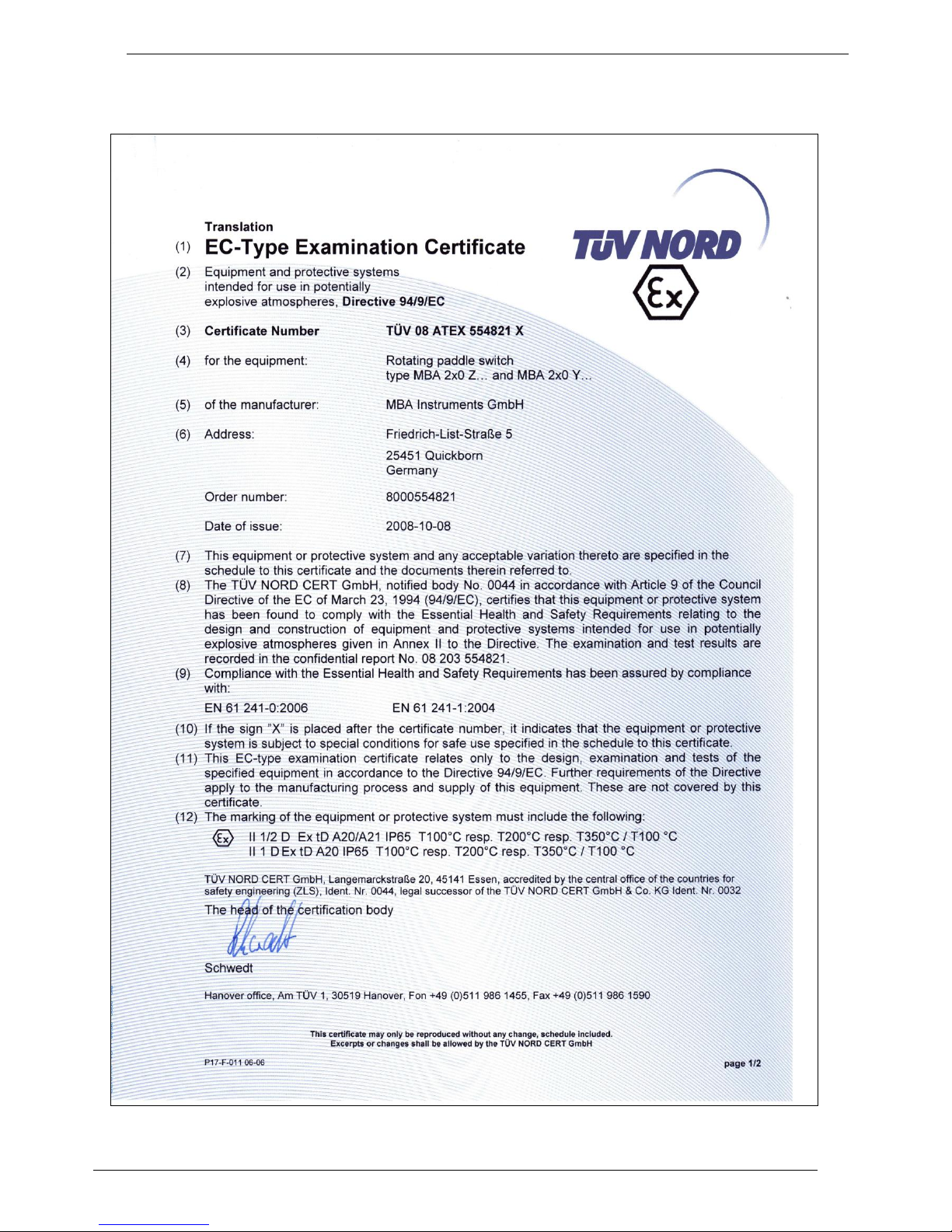
7.6 EC-Type Examination Certificate . . . . . . . . . . . . . . . . . . . .13
Page 3
Bin-level Indicator MBA200
MBA200
·
Operating Instructions 8011417 V 2.2
·
© MBA Instruments GmbH Germany 2
1
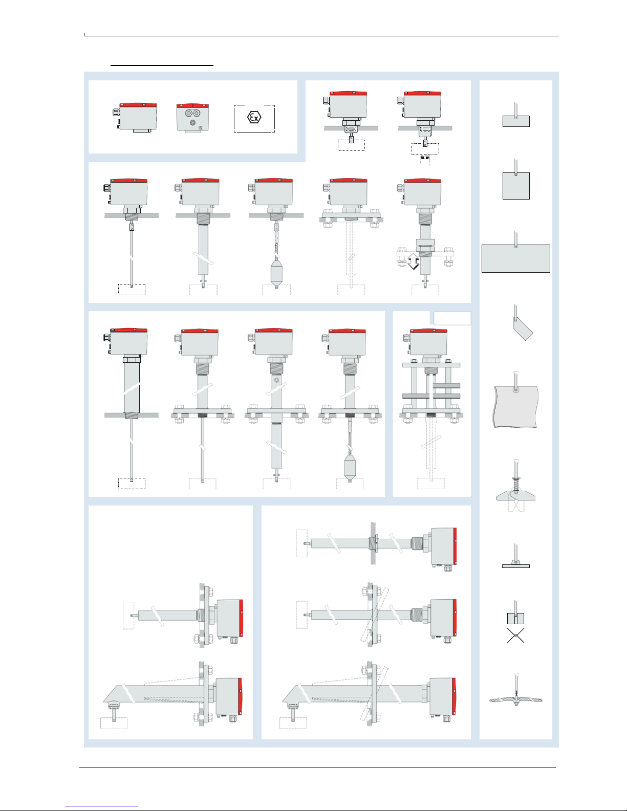
Product overview
ATEX
Zone 20/21
(Option)
80 °C
200 °C
500 °C 800 °C
80 °C
200 °C
350 °C
Page 4
3 MBA200
·
Operating Instructions 8011417 V 2.2
·
© MBA Instruments GmbH Germany
Bin-level Indicator MBA200
2
Product description
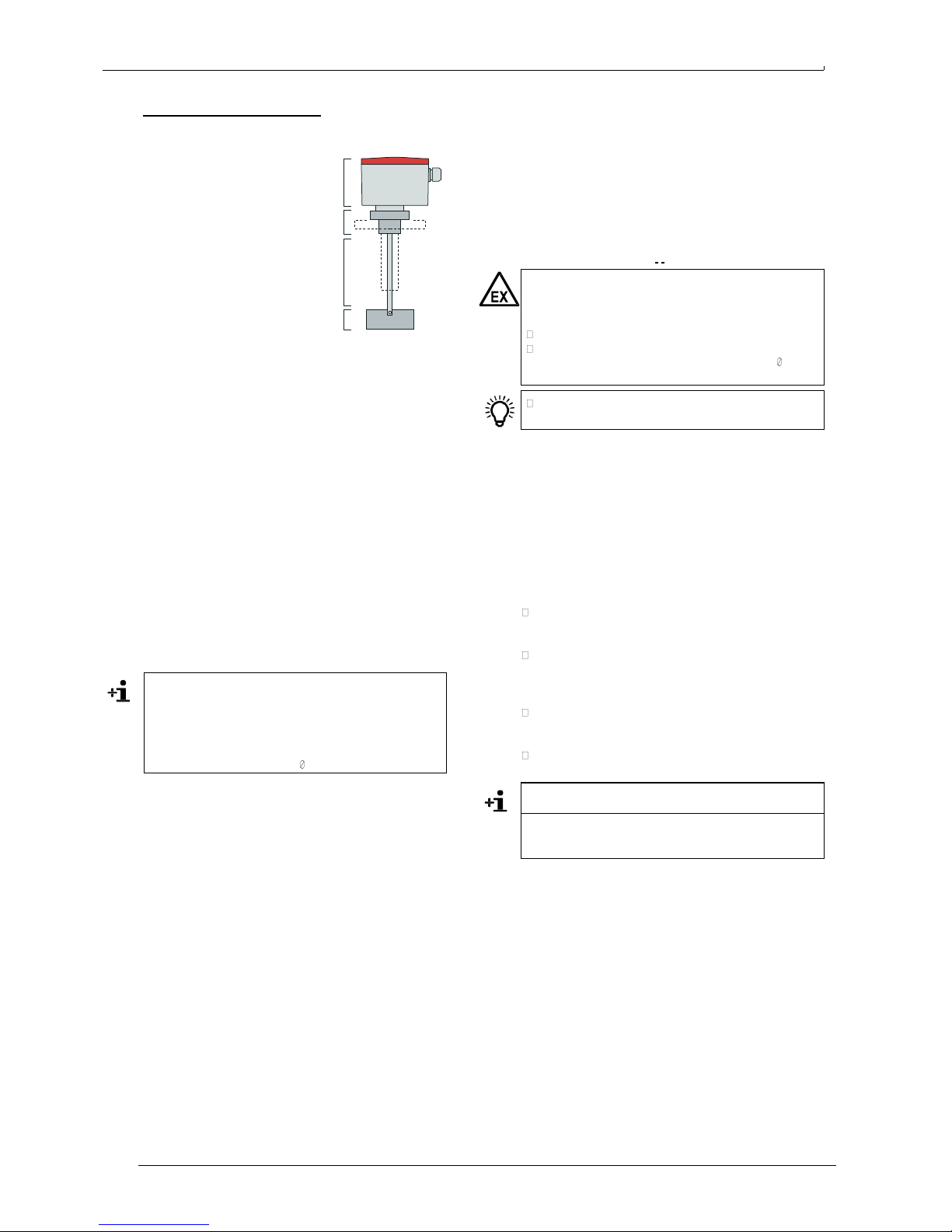
2.1 Unit components
1. Unit head: contains the motor
drive and electronic components.
Three different types available.
1
2. Process connection: thread or
flange. Attached to the outer wall
2
of the bulk materials container.
Holds the unit head on the
outside and the protective tube (if
provided) on the inside. Many
3
versions available for individual
adaptation to the actual container.
3. Shaft: Connects the paddle to the
4
unit head. Various lengths
available (large sizes divided in
2.4 Appropriate use
Range of application
MBA bin level indicators are rugged electromechanical
sensors, designed to detect the presence of bulk material at
the place of installation and thus to control the filling of bulk
material containers. Possible applications depend on the
configuration of the individual unit.
Bin level indicators of the MBA200 series can be used with
industrial bulk materials from organic and mineral
substances. MBA units may not be affected by chemical
aggressive gases or fluids.
5
WARNUNG: Explosion hazard
A MBA200 bin level indicator may only be used in
explosion-hazardous locations if the individual
specifications of the unit complies with this use.
Check nameplate and accompanying papers.
Check whether the specifications of the EC-Type
two sections) and a flexible steel cable as the shaft.
4. Paddle: Stops the shaft rotation when the bulk material
surrounds the paddle. Solid/flexible/foldable versions
available with different size or material.
5. Protective tube (option): Covers the shaft inside the
container. Various lengths available. Versions: open tube
for vertical mounting (great lengths delivered in two
sections); tube for horizontal mounting with additional
shaft bearing at the end; angled shaft bearing with
horizontal tube and a vertical shaft.
2.2 Principle of operation
The electric motor in the head makes the shaft and the
paddle rotate slowly. When the bulk material surrounds the
paddle, the rotation is blocked. The counter-torque is used to
turn the motor mechanism against a switch which then turns
the motor off. The switch has a second contact (potentialfree) which is used for the status indication.
As soon as the bulk material releases the paddle again, a
spring pulls the motor mechanism back into the working
position. Thus the switch is released and the paddle starts
rotating again.
The motor mechanism requires approximately 3 seconds to
indicate stopping or restarting of the paddle (switching delay
due to the mechanical sequence).
Additional indication delay can be effected by
●
the characteristics of the bulk material
●
torsion effects (e.g. cable shaft, rubber paddle)
●
electronic switching delay ( page 9, § 3.5)
2.3 Optional equipment
General options
●
Special seal (DTR): Protection against gases, vapours,
and abrasive bulk materials.
●
Compensating membrane: Membrane which allows
diffusion of water-vapour and thus can balance out the
humidity inside the unit head. Moreover, the membrane
will burst if the pressure inside the unit head increases
strongly due to operational trouble, which allows the use
on containers with an internal pressure up to +1 MPa
(option »10 bar«).
●
Heating in the unit head: Allows use at low ambient
temperatures.
●
Height adjustment: A clamping sleeve which guides the
protective tube of the extension arm and allows fixating
the extension arm at variable insertion depth.
Electronic options (only for type 220 and 230)
●
Action monitoring: A Hall sensor in the unit head
monitors the shaft rotation. The error status is indicated
by means of a relay contact.
●
Indicating LED light: Indicates the current status.
Examination Certificate must be complied with ( page 13,
§ 7.6).
If there is any doubt whether the unit may be used for
the desired application or not: Ask the manufacturer.
Design options
Variable design features are, for example:
●
Paddle design, size, and material
●
Shaft design and material
●
Sealing of shaft against enclosure
The corresponding properties for the unit can expand or
restrict the range of possible applications (e.g. suitability for
a particular type of bulk material). Please note carefully the
specifications for your particular unit.
2.5 Responsibility of the
user
Use the device only as described in these Operating
Instructions. The manufacturer bears no responsibility for
any other use.
In addition to these Operating Instructions, follow all local
laws, technical rules and company-internal operating
directives applicable at the respective installation site of
the equipment.
No components may be removed from, added to or
changed on the device unless this is described and
specified in the official manufacturer information.
In explosion-hazardous locations: Prior to installation and
operation, observe the European standard EN 61241-14.
EN 61241-14: Electrical apparatus for use in the presence
of combustible dust – selection and installation.s
Product versions which are certified for use in explosionhazardous locations have been tested and certified
according to EN 61241-0 and EN 61241-
Page 5
MBA200
·
Operating Instructions 8011417 V 2.2
·
© MBA Instruments GmbH Germany 4
Bin-level Indicator MBA200
3
Installation
Do not remove, add, or change any of the components
in the instrument unless these changes are described
and specified in a manufacturer’s official information.
Otherwise the manufacturer’s guarantee becomes invalid,
and the certification for use in explosion-hazardous
locations (if provided) is no longer valid.
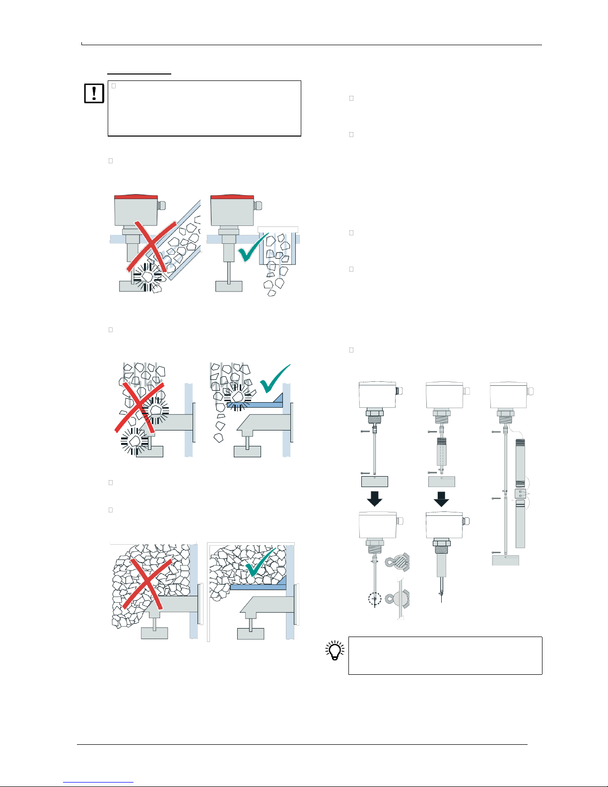
3.1 Protective roof / deflector
If at all possible, place the MaihakMBA unit in a position
where falling bulk material will not directly strike onto the
shaft or the paddle.
For heavy bulk materials that could damage the shaft or the
paddle:
If required, install a stable deflector or protective roof in
the container which protects the shaft and the paddle
against direct impact of falling bulk material.
3.2 Assembly (if required)
If shaft, paddle, and protective tube (if provided) were
shipped dismantled (for safe and easy transport):
Install the shaft: Guide the top end of the shaft into the
shaft sleeve of the unit head. Use a split-pin to connect
both parts (push it through and spread it out). – With twopart shafts: Join both parts of the shaft in the same way.
Assembling the protective tube (for divided protective
tubes): Take the locking screws out of the connecting
coupling sleeve. Screw one of the protective tube parts
into the coupling sleeve – up to about the middle of the
coupling sleeve. Then screw-in the other part from the
other side and firmly attach both parts of the protective
tube. – Recommendation: Now make two small
countersunk holes in the coupling sleeve, which will fix
the position of the locking screws (use a max. 3.2 mm
diameter drill guided through the screw holes of the
coupling sleeve). – Put in the locking screws and tighten.
Install the protective tube (for units with a protective
tube): Apply a threadlocking adhesive (such as »Loctite«)
to the thread of the protective tube and screw the
protective tube into the threaded sleeve, as far as it goes.
Shortening the flexible cable shaft (if required): Remove
the tensioning weight from the end of the cable (undo the
locking screw and pull out the cable). At the place where
the cable must be cut, wrap some adhesive tape firmly
around the cable, to protect against wire particles
shooting from the cable. Wear protective goggles/
glasses. Then cut the cable with a suitable wire cutter or
a cutting disk. Remove the adhesive tape and attach the
tensioning weight again.
Install the paddle: Guide the flat end of the paddle into
the slot of the shaft and attach it with the split-pin
provided (push it through and spread it out).
1.
1.
5. 6.
2.
If the bulk material is heavy or can form large clumps:
Install a stable protective roof within the container to
shield the shaft (and the extension arm) from the weight
of the bulk material.
Provide sufficient space between protective roof and
paddle to make sure that the bulk material can reach the
paddle.
2.
3.
1
4.
3.
2.
7.
1 … 7 = order of assembly
●
It may be necessary (or advantageous) to install the
paddle at the very end of the installation procedure.
●
Recommendation: Apply a threadlocking adhesive
(such as »Loctite«) to all the locking screws.
Page 6
5 MBA200
·
Operating Instructions 8011417 V 2.2
·
© MBA Instruments GmbH Germany
Bin-level Indicator MBA200
3.3 Installation
3.3.1 Operational conditions
Observe temperature specifications on the nameplate
(example page 11, § 7.1, explanations page 4, § 2.4).
Keep the following pressure limits:
Standard configuration
–50 … +300 kPa
(–0.5 … +3.0 bar)
Version D10 (equipped
with burst membrane in the
unit head)
max. 1.0 MPa (10 bar)
In explosion-hazardous
locations
80 … 110 kPa
(0.8 … +1.1 bar)
3.3.2 Installation position
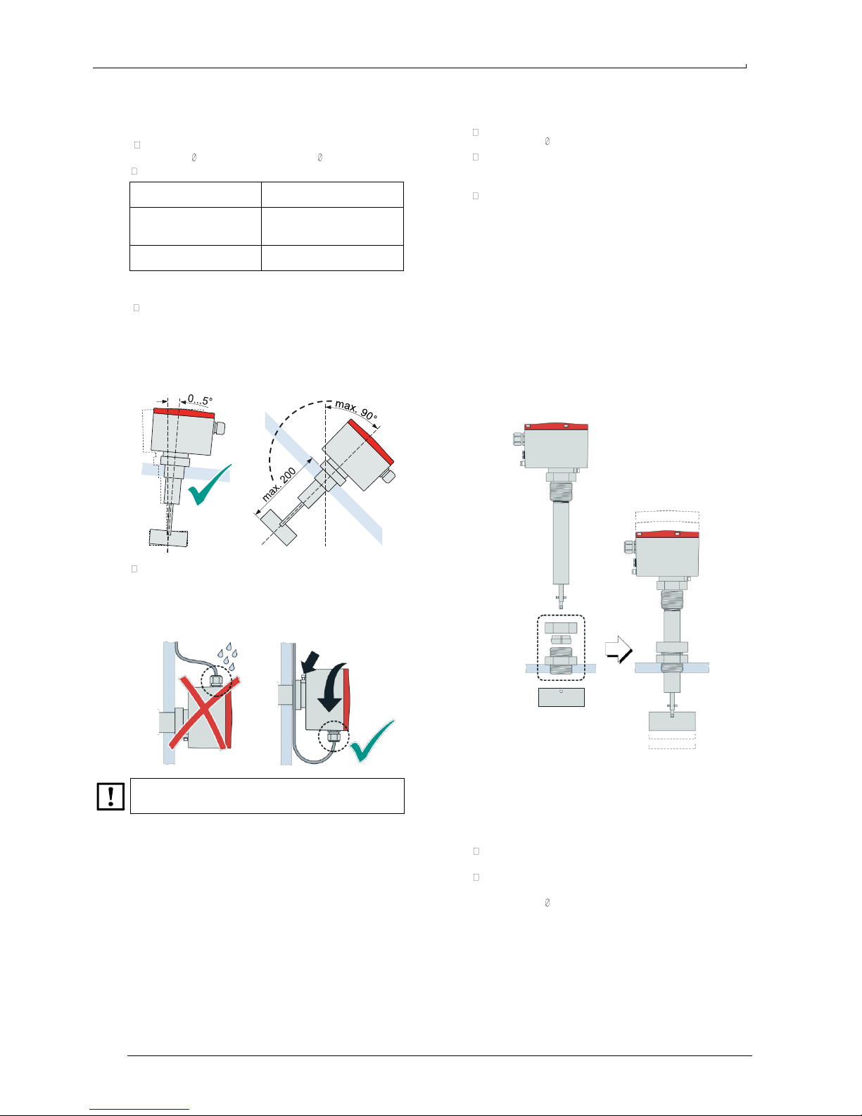
Units without additional shaft bearing in the extension
arm: Use only with a vertically suspended shaft (±5°).
Exception: If the shaft is rigid (not flexible) and not longer
than 200 mm and the bulk material is light-weighted, an
angle of inclination of max. 90° is permissible (allows side-
mounting with horizontal shaft).
In case of lateral installation (horizontal shaft): Install the
unit in such a way that the cable glands are on the
underside of the housing.
The unit head can be turned (2) after the clamping screw (1)
on the underside has been released.
3.3.3 Attachment
Standard versions
Attach the MBA process connection to the container.
(dimensions page 12, § 7.5).
If protection class IP 65 is required (European standard
EN 60529): Provide a suitable water/dust sealing
between device and container.
If the paddle does not go through the container opening:
Detach the paddle before mounting and re-install after
mounting.
Height adjustment (option)
The height adjustment device is a clamp-ring fitting which
allows to fix the protective tube at variable insertion depth.
1. Install the threaded base part of the fitting in the container
wall.
2. Put the clamping nut and the clamping ring over the
protective tube.
3. Guide the protective tube through the base part of the
fitting (caution: do not damage the sealing rings inside
the fitting) and bring it into the desired position.
4. Guide the clamping ring into the fitting. Screw-up and
tighten the clamping nut.
5. Install the paddle.
1
2
The clamping screw must be fixed to achieve operational
condition.
Temperature protection by height adjustment
The height adjustment device can also be used to keep the
unit head away from high container temperatures.
●
Important: This feature applies only to units equipped
with »DTR« type bearings.
Mounting instructions:
Adjust the height to a level where the distance between
unit head and container is at least 200 mm (7.9").
If the container is equipped with a thermal insulation:
Remove the thermal insulation around the protective tube
(instructions page 7, § 3.3.4).
When these conditions are kept, the unit can be used with
container temperatures up to 200 °C (392 °F).
Page 7
MBA200
·
Operating Instructions 8011417 V 2.2
·
© MBA Instruments GmbH Germany 6
Bin-level Indicator MBA200
3.3.4 Temperatures of the distance tube
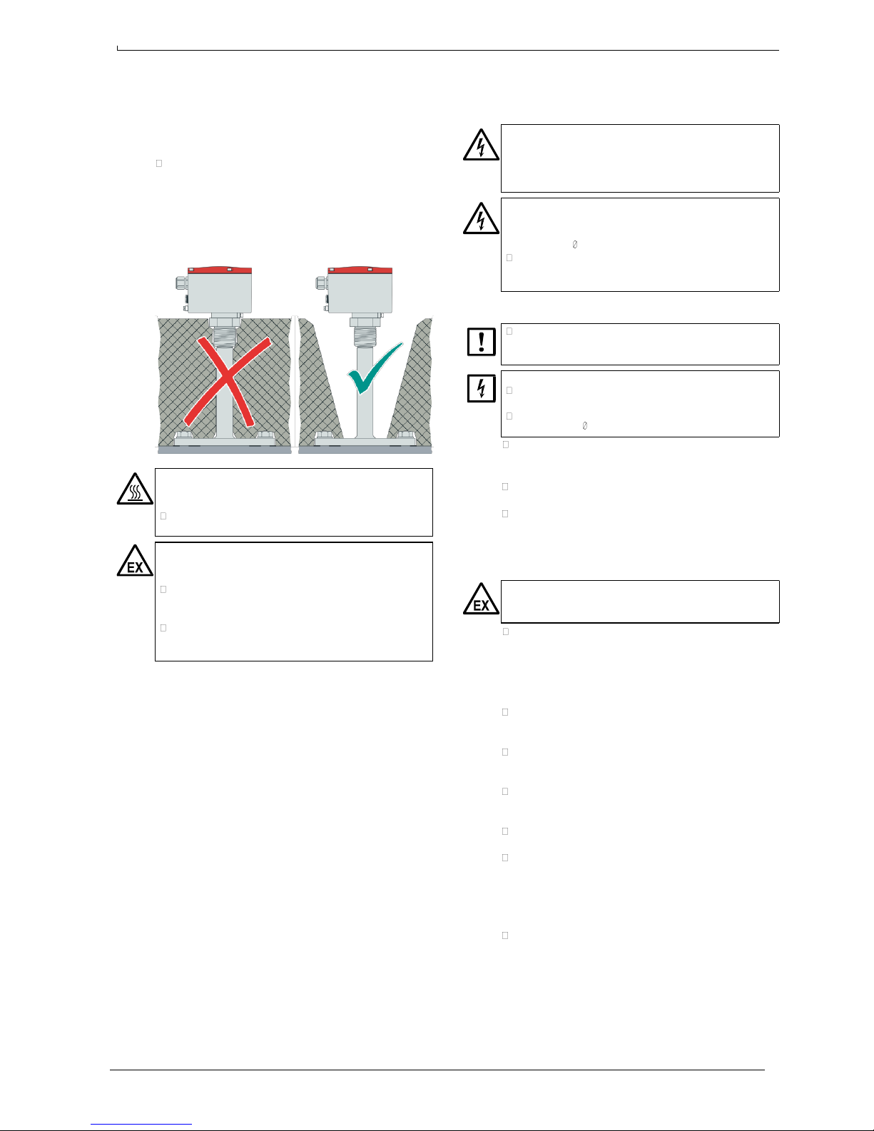
Unit versions for high container temperatures above 80 °C
are equipped with a distance tube between unit head and
connection thread/flange. The purpose of the distance tube
is to keep high temperatures away from the unit head (max.
60 °C).
If the container is equipped with a thermal insulation:
Keep the distance tube free of thermal insulation, in order
to allow cooling by the ambient air. Do not cover the
distance tube with the insulation of the container.
Otherwise distance tube will not provide the required
cooling effect. Overheat can cause malfunctions and
damage the unit head.
WARNUNG: Risk of injury
The distance tube is possibly hot enough to burn skin
immediately when being touched.
If the container is hot: Protect the distance tube against
accidental touching.
WARNUNG: Explosion hazard by dust contamination
The surface temperature of the distance tube can be
significantly higher than the unit head temperature.
Check if the dust-explosion limit value can be exceeded
when the surface of the distance tube is covered with
dust.
If this hazard exists: Make sure that the distance tube
cannot be contaminated with dust, or that the distance
tube is periodically cleaned as a preventive measure.
3.4 Electrical connection
3.4.1 Important safety notes
WARNUNG: Free electrical contacts inside the unit head
Before opening the unit head, shut off the mains power
supply and all connected signal voltage. The electrical
circuits inside the unit head are not protected against
physical contact.
WARNUNG: High voltage inside the unit head (type 230)
In the type 230 unit head, there are always contacts with an
output of 230 and 115 V, even if the unit is powered with a
lower voltage ( page 9, § 3.4.6).
Observe this information when operating the unit with
open unit head for service purposes. Take care. Give a
warning to other persons.
3.4.2 Safe electrical installation
A MBA200 should be installed and set-up by skilled
persons who can assess the tasks given and consider
the dangers involved.
The MBA200 is not equipped with a power switch or fuse.
Install an external power switch which can switch on and
off the mains power supply to the MBA200.
Provide an external mains fuse for the MBA200 (power
consumption page 11, § 7.2).
Use power cable with following conductor cross sections:
– Massive wire: max. 2,5 mm²
– Stranded wire: max. 1,5 mm²
Use cables which are specified for an ambient
temperature of at least 60 °C (140 °F).
Protect all cables against heat. Avoid contact with hot
surfaces (for example, the container wall). Consider
thermal radiation and heat accumulation.
3.4.3 Protection against explosion
WARNUNG: Explosion hazard
If the unit is used in an explosion-hazardous location,
the following criteria must be observed:
Certification:
– Check if the individual unit is applicable to the use in
the actual explosion-hazardous location (see
nameplate and delivered documents).
– Observe the „special conditions“ which are specified
in certification documents.
Equipotential connection: In addition to the protective
earth connection (PE), install an equipotential bonding,
using the terminal on the outside of the unit head.
Cables: Use only cables which fit to the cable glands. For
standard product versions, the outer diameter of the
cables must be 6 … 12 mm.
Cable glands: The built-in cable glands may only be
replaced by components which are certified for the use in
the actual explosion-hazardous location (ATEX-certified).
Fixed installation: Fix all connected cables in place over
their entire length.
Sparks: Prevent generation of sparks inside the
container. Sparks can be generated when the shaft or the
paddle collides with metal parts. If the MaihakMBA is
equipped with a flexible shaft, sparks could be produced
when the shaft cable swings and the paddle collides with
the container wall.
Installation standard: Make the installation in accordance
to the European standard EN 61241-14.
Page 8
7 MBA200
·
Operating Instructions 8011417 V 2.2
·
© MBA Instruments GmbH Germany
Signal Signal Status
24 VDC
24 VA
C
98
°C
ON OFF
Bin-level Indicator MBA200
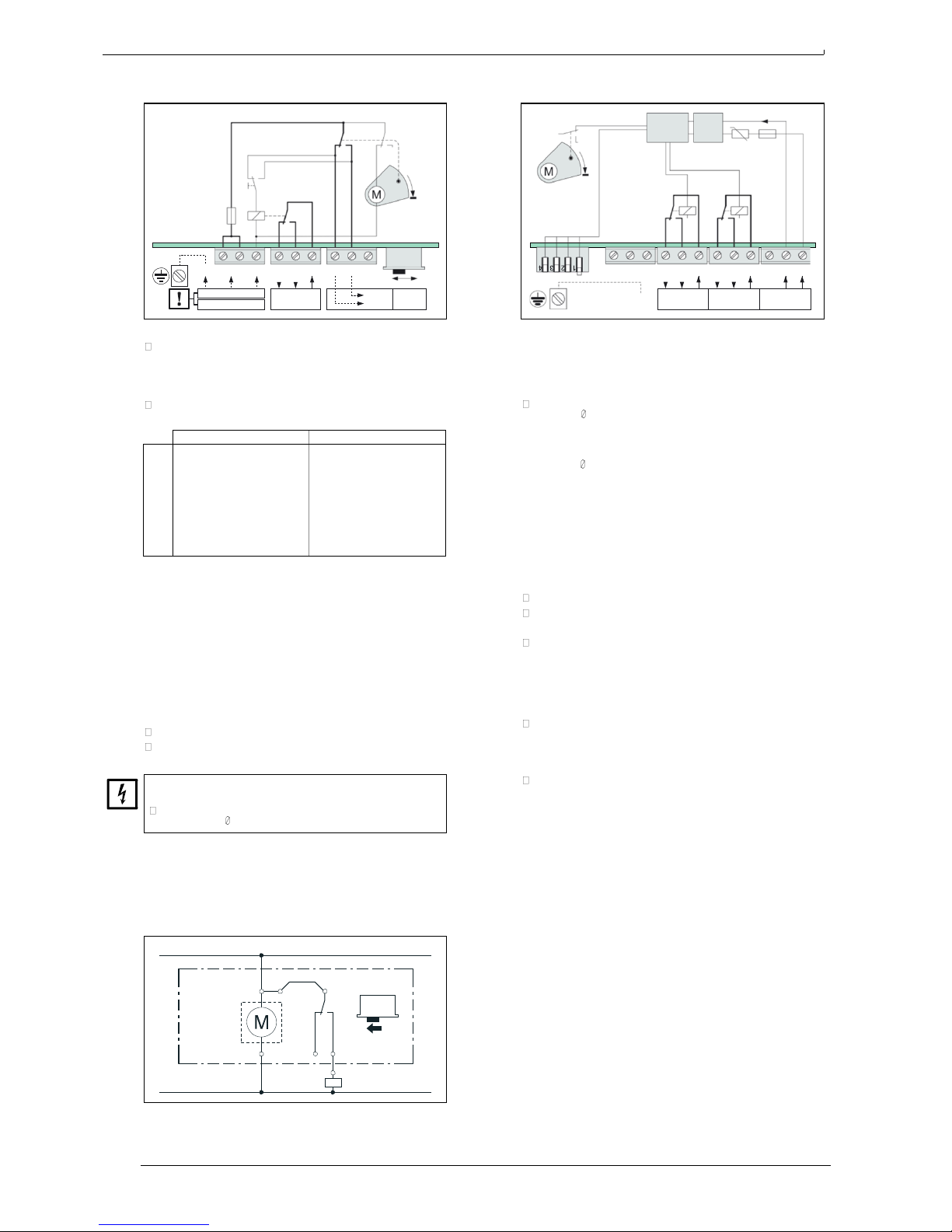
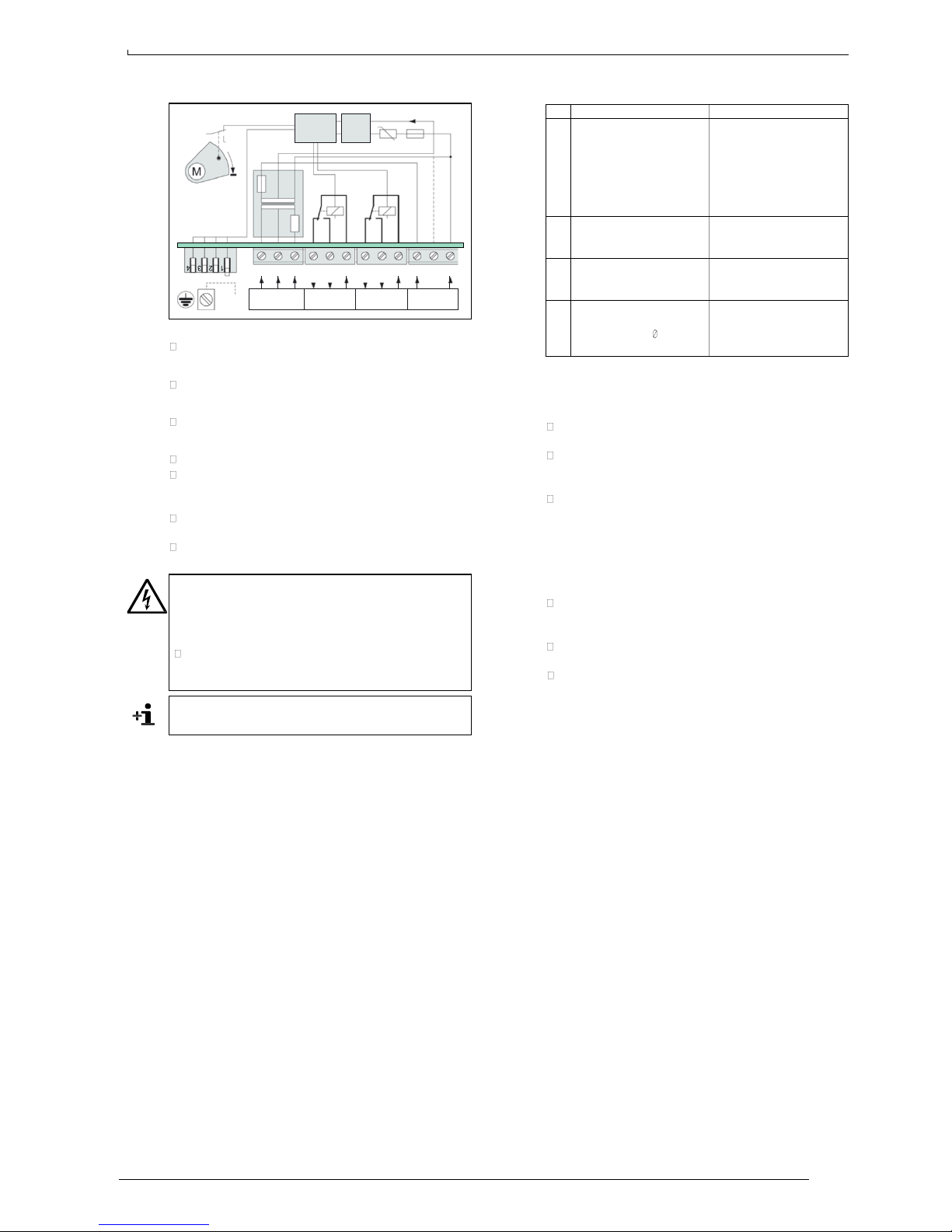
3.4.4 Type 210 (115 or 230 VAC)
3.4.5 Type 220 (24 VAC/DC)
S3
S2
μC
AC/DC
S2
stab.
PTC
24 V
0 V
98
°C
H L
S1
MBA
210
K1
MBA
220
S1
K1 K2
PE L1 L1 N
115 VA
C
1 2 3 4 5
Stop
S1
H
L
mech.
1 2 3 4 5 6 24 0
230 VAC
Rotat.
Status
PE
Signal contact
Use the potential-free make&break relay contact K1 for
the level indication.
Depending on setting of S1, relay K1 is activated either when
the paddle is rotating or when the paddle is stopped.
Select which setting provides a fail-safe operation in your
system:
Position H
Position L
S1
Fail-safe FULL level
indication:
K1 is activated when the
paddle is rotating.
During power failure, the
»full« status is indicated
(like paddle is stopped).
Fail-safe EMPTY level
indication:
K1 is activated when the
paddle is stopped.
During power failure, the
»empty« status is
indicated (like paddle is
rotating).
Status output
S3 switches the power voltage (L1) between terminal 4 and
5, directly actuated by the motor mechanism.
Permissible contact load
Direct current: 60 VDC, 1 A (DC 1)
Alternating current: 250 VAC, 2 A (AC 15)
Power supply
Mains supply voltage: 115 VAC or 230 VAC
(see nameplate)
–15 %/+10 %
Connect the power supply to terminals L1 and N.
Connect the protective earth (PE) conductor to the
terminal in the unit head.
Overvoltage can immediately destroy internal electronic
components.
Observe the mains voltage specification on the
nameplate ( page 11, § 7.1).
Overheat fuse
Type 210 is equipped with an overheat fuse which cuts off
the power supply when the internal temperature exceeds
98 °C (208 °F). When the fuse is blown, the electronics
board needs to be replaced for repair.
Wiring example as FULL level indicator
Signal contact
Use make&break relay contact K1 for the level indication
(paddle rotating / stopped). Depending on setting of S1-1,
relay K1 is activated either when the paddle is rotating or
when the paddle is stopped.
Select which setting provides a fail-safe operation in your
system ( § 3.5).
Status contact
Relay contact K2 is used to indicate a fault condition. Full
information page 11, § 6.
Permissible contact load
Direct current: 60 VDC, 1 A (DC 1)
Alternating current: 250 VAC, 2 A (AC 15)
Power supply
Permissible power supply voltage:
Direct current: 24 VDC –10 %/+30 %
Alternating current: 24 VAC –15 %/+10 %
Provide an external power fuse.
Connect the power supply to terminals »24 V« (+) and
»0 V« (–).
Connect the protective earth (PE) conductor to the
terminal in the unit head.
Power overload fuse
The power overload fuse cuts off the internal power supply
in case of high current.
When overload fuse has been released: Switch off the
power supply externally and wait for approximately one
minute for the fuse to cool down; then switch on the
power supply again.
If the overload fuse is released again: Search for the
trouble; or replace the electronics board, if required.
Overheat fuse
The overheat fuse cuts off the power supply when the
internal temperature exceeds 98 °C (208 °F). When this fuse
is blown, the electronics board needs to be replaced for
repair.
L1
MBA
210
L1 3
S1
K1
H
N
1 2
N
fill control
Page 9
MBA200
·
Operating Instructions 8011417 V 2.2
·
© MBA Instruments GmbH Germany 8
230 /
115
VA
C
Signal Status
42
VA
C
S1
ON
OFF
1
Fail-safe FULL indication:
K1 is activated when the
paddle is rotating. During
power failure, the »full«
status is indicated (like
paddle is stopped).
Fail-safe
EMPTY indication: K1 is
activated when the paddle
is stopped. During power
failure, the »empty« status
is indicated (like paddle is
rotating).
2
Switch-on delay: K1
switches on with a delay of
4 s.
No electronic switch-on
delay.
3
Switch-off delay: K1
switches off with a delay of
4 s.
No electronic switch-off
delay.
4
The action monitoring
option is built-in
(consequences page 11,
»Fault indication«).
The action monitoring
option is not built-in.
ON OFF
98
°C 98 °C
Bin-level Indicator MBA200
3.4.6 Type 230 (42/115/230 VAC)
AC/DC
24 V
3.5 DIP switch settings for type 220/230
S2
μC
stab.
PTC
0 V
98
°C
MBA
230
S1
PE
230 115
K1
K2
N 1 2 3 4 5 6
42 0
Signal contact
See type 220.
Status contact
See type 220.
Permissible contact load
See type 220.
Power supply
Provide an external power fuse.
For 115 or 230 V power voltage: Connect L1 conductor
to terminal »115« or »230«, respectively. Connect N
conductor to terminal »N«.
For 42 V power voltage: Connect L1 conductor to
terminal »42«. Connect N conductor to terminal »0«.
Connect the protective earth (PE) conductor to the
terminal in the unit head.
WARNUNG: Internally generated power voltage
The power terminals »230« and »115« will have a voltage
output of 230/115 V, even if the unit is used with a lower
power voltage (due to power feedback through internal
transformer).
Observe this information when operating the unit with
open unit head for service purposes. Take care. Give a
warning to other persons.
3.6 Closing the housing
3.6.1 Closing the cable glands
Lay the connected cables internally in such a way that
they do not interfere with the mechanism.
After the cables have been installed, the cable glands
must be closed-off to be dust-tight and spray-water
resistant.
Unused cable glands must either be blocked-off with
stoppers or replaced with closing caps. If used in
explosion-hazardous locations, these parts must be
applicable to explosion-hazardous locations (ATEXcertified).
3.6.2 Closing the cover
Before closing cover of the unit head, check whether
there are any foreign bodies inside the unit head (such as
rests of cable). Remove them.
Visually check the sealing of the cover. Clean or replace if
necessary.
Put the cover in place and screw it up tight.
Permissible power voltage tolerance: –15 %/+10 %
Internal fuses
Type 220 is equipped with three internal fuses:
●
Power overload fuse: see type 220.
●
Overheat fuse: see type 220.
●
Overheat fuse in the power transformer: cuts off the
transformer circuit at 98 °C (208 °F).
Page 10
9 MBA200
·
Operating Instructions 8011417 V 2.2
·
© MBA Instruments GmbH Germany
Bin-level Indicator MBA200
4
First Start-up
4.1 Switching on
WARNUNG: Health risk / Explosion hazard
During operation, the unit head and the cable gland(s) must
be correctly closed and sealed. Otherwise the specified
type of protection and the specified explosion protection
(option) is not guaranteed.
4.2 Function test at first start-up
4.2.1 Check the operative function
After the first start-up, check the indicating function:
1. Allow the paddle to rotate freely: check the »empty«
indication.
2. Stop the paddle by hand: check the »full« indication.
4.2.2 Check for triggering by the bulk material
Procedure
While visually watching the bulk material level, fill and
empty the bulk materials container up to the MBA unit,
and check that the indicating function is correctly
triggered. This test should be made several times.
If the MBA unit does not correctly indicate the level
status: Check the options for mechanical adaptation (see
below) and carry them out if necessary.
If the type of bulk material has been changed:
Do this test/adaptation again.
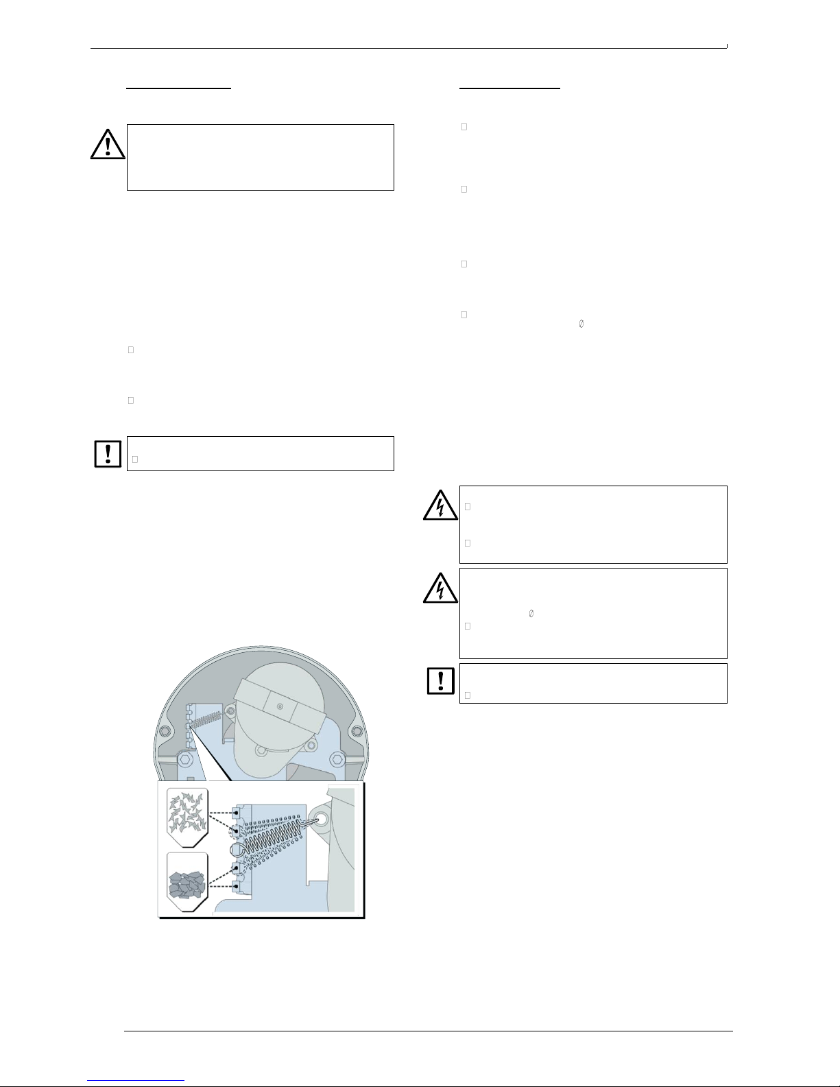
Possible ways of adapting the unit
●
Spring tension (see figure):
– More sensitive setting (less tension), for light bulk
material: Bring the spring to closer position.
– Less sensitive setting (more tension), for heavy bulk
material: Bring the spring to a more distant position.
●
Paddle size:
– To make it more sensitive (for lighter bulk material):
Install a bigger paddle.
– To make it less sensitive: Install a smaller paddle.
●
Spring type: If required, install a stronger or weaker
spring (3 different types available).
5
Maintenance
5.1 Recommended maintenance work
Clean the moving external parts: Clean off deposits and
dirt on paddle and shaft, using a (soft) scraper and/or a
brush. Do not use force. Caution: Do not damage the
shaft sealing. Do not allow bristles to get between the
shaft and the shaft sealing.
Inspect the parts subject to wear (highly recommended
in case of abrasive bulk material): Make a visual
inspection of the parts which protrude into the container
(shaft, paddle, etc.). Pay special attention to the
connecting parts (split-pins, etc.). Replace damaged or
dubious parts.
Clean the protective tube (only if the unit is equipped
with an open protective tube): Clean the inside of the
protective tube to make sure that the shaft can always
freely rotate.
Clean the distance tube (if existing – if required for
explosion protection page 7, § 3.3.4): Remove dust
contamination from the distance tube.
5.2 Preventive function check
If the indicating function is seldom triggered during operation
(e.g. if the level indicator is used as a safety switch):
1. Inform the connected stations that a test will be carried
out.
2. Stop the paddle by hand / allow the paddle to rotate
freely, and check the correct status indication.
5.3 Safety information on opening
WARNUNG: Health risk / Explosion hazard
Before opening the unit head: switch-off the power
supply and any connected signal voltage at an external
point. (Note: the level indication is thereby disabled.)
Only open the housing when you are absolutely sure
that there is no possible danger.
WARNUNG: High voltage inside the unit head (type 230)
In the type 230 unit head, there are always contacts with an
output of 230 and 115 V, even if the unit is powered with a
lower voltage ( page 9, § 3.4.6).
Observe this information when operating the unit with
open unit head for service purposes. Take care. Give a
warning to other persons.
Severe dirtiness inside the unit head can affect the proper
functioning of the unit.
Protect the inside of the unit head from getting dirty.
5.4 Removing the unit head (repair note)
The unit head can easily be separated from the process
connection, without opening the process connection:
1. If the unit head is to be removed completely, disconnect
the electric cables first.
2. Loosen the fixing screw on the underside of the unit head
for approximately 3 mm (3 … 4 turns).
3. Carefully pull the unit head from the process connection
(along the direction of the shaft). This requires some
strength, due to adhesion and friction of the sealing: use
skilful power, but no brutal force; protect yourself against
tumbling and falling in the case that the unit head goes
suddenly free.
Re-assembly is made in reverse order.
Page 11
MBA200
·
Operating Instructions 8011417 V 2.2
·
© MBA Instruments GmbH Germany 10
7.2
Electrical data
Mains voltage:
see nameplate
Tolerance:
see text in this manual
AC mains frequency:
50 … 60 Hz
Power consumption
– without heating:
– with heating:
3 VA
10 VA
Response time:
– quick-rotating version:
3 s
0,6 s
Bin-level Indicator MBA200
6
Fault indication
Operation principle of the fault status indication
MaihakMBA type 220 and 230 are equipped with the
»Status« switch contact for fault indication, which is driven by
relay K2. During normal operation, K2 is activated; in case of
an internal fault, K2 is deactivated. This also happens during
power supply failure. Please note: In fault condition, also
relay K1 (which drives the »Signal« contact) is deactivated,
in order to provide a fail-safe operation; however, this is only
achieved if the K1 function mode is properly selected
( page 9, § 3.5)
Fault indication caused by action monitoring
If action monitoring is built-in (option), the following
conditions will trigger the fault status indication:
– The shaft does not rotate, although the motor is not in the
stop position (switch S2).
Possibly defective: switch S2, motor, rotation sensor.
– The shaft is rotating, although the motor is in the stop
position (switch S2). – Possibly defective: switch S2.
Remedy: Check if internal micro-switches are blocked.
If this does not help: Replace the unit head.
General causes for fault indication
Without the action monitoring option, the following conditions
will trigger the fault status indication:
●
Power supply has failed.
●
An internal fuse is defective.
●
Action monitoring is activated although it is not built-in.
Remedy: Correct the setting of S1-4 ( page 9, § 3.5).
7
Technical data
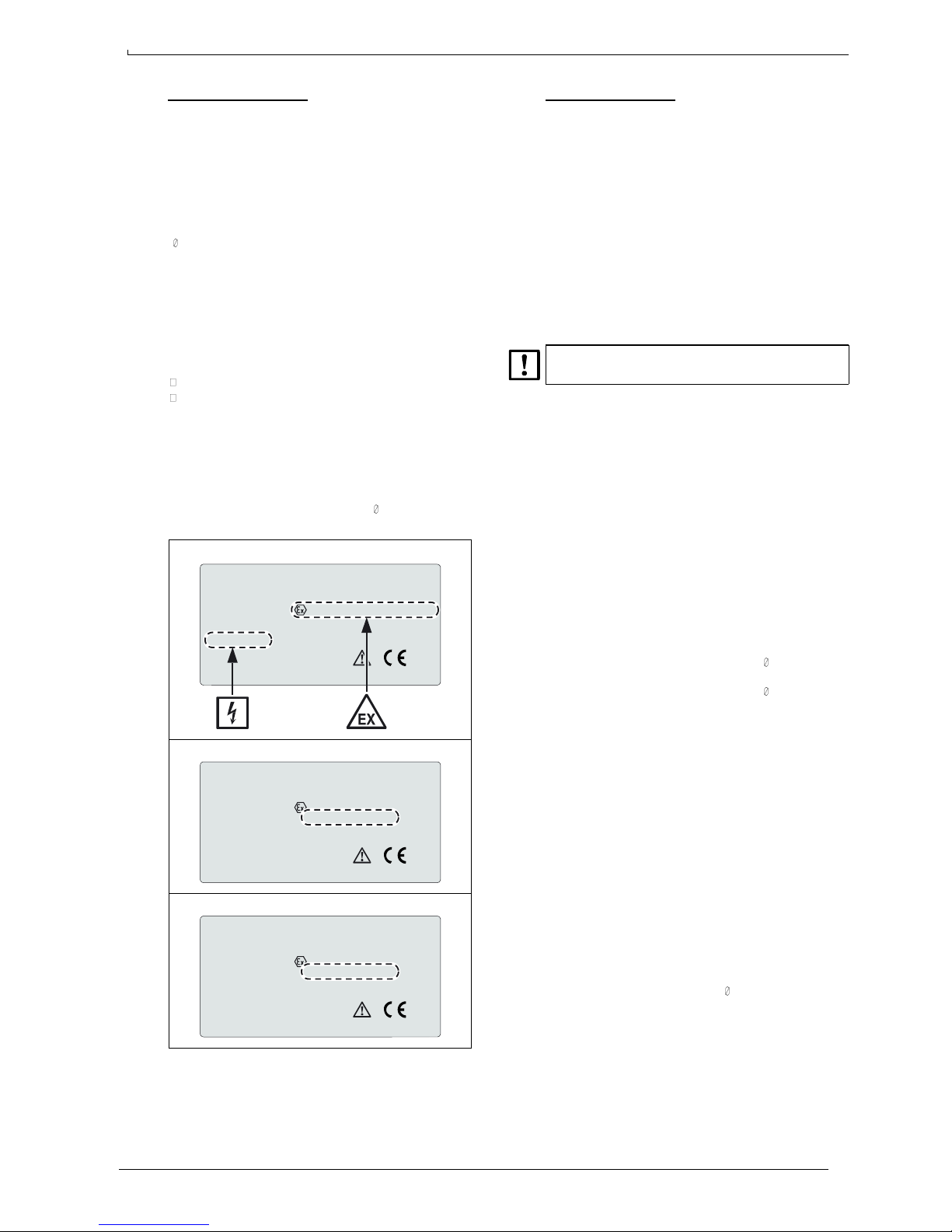
7.1 Specifications on the nameplate
●
Unit type (for example, »210«) and version code
●
Required mains power supply (for example, »230VAC 50/
60 Hz«)
●
Explosion protection class (for example, »II 1D …«),
including the enclosure protection class (for example,
»IP 65«) and maximum surface temperatures:
– The first temperature value applies to the components
protruding into the container.
– The second temperature value applies to the unit
head.
●
Allowable ambient temperature (Ta) and »Ex« zone (for
example, »Z20«):
»extern« = for the unit head
»medium« = for components protruding into the container
Specifications on the nameplate apply with higher priority.
Important specifications on the nameplate (example)
MBA Instruments
MBA 210YAA1N1A00300AX
II 1D Ex tD A20 IP65 T100°C/T100°C
7.3 Ambient conditions
Ambient temperature outside the container
– without heating: –15 … +60 °C (5 … 140 °F)
– with heating: –45 … +60 °C (–49 … +140 °F) /
PN 214000-G 123456
SN 654321 05.03
TÜV 08 ATEX 554820 X
T
a
Z20/extern: –15°C... +60°C
–30 … +60 °C (–22 … +140 °F)
1
230VAC 50/60Hz 10VA T
a
Z20/medium: –30°C... +80°C
QA
0044
MBA Instruments D-25451 Quickborn Made in Germany
Nameplate stating the Certificate of Conformity (example)
MBA Instruments
MBA 210YAA1N1A00300AX
Allowable temperature inside the container
– standard versions: –30 … +80 °C (–22 … +176 °F)
– special versions: see nameplate ( § 7.1)
Max. surface temperature
of the MBA unit: see nameplate ( § 7.1)
7.4 Product materials
Product materials in contact with bulk material
Enclosure, protective tube: steel/painted steel/stainless
steel2, aluminium
3
Sealing: Viton or PTFE2 or graphite
4
PN 214000-G 123456
SN 654321 05.03
II 1D Ex tD A20 IP65 T100°C/T100°C
TÜV 08 ATEX 554820 X
T
a
Z20/extern: –15°C... +60°C
Materials of the unit head
Enclosure body: aluminium
230VAC 50/60Hz 10VA T
a
Z20/medium: –30°C... +80°C
QA
Enclosure cover: painted aluminium
0044
MBA Instruments D-25451 Quickborn Made in Germany
Nameplate stating the EC-type Examination Certificate (example)
MBA Instruments
MBA 210YAA1N1A00300AX
Enclosure sealing: silicone (VMQ)
Cable glands: PA (sealing: NBR) / option:
nickel-plated brass (sealing:
NBR/FPM, PA/PVDF)
Sealing plug: PA
Balancing membrane: polyester/ePTFE
(sealing: silicone)
PN 214000-G 123456
SN 654321 05.03
II 1D Ex tD A20 IP65 T100°C/T100°C
TÜV 08 ATEX 554821 X
T
a
Z20/extern: –15°C... +60°C
230VAC 50/60Hz 10VA T
a
Z20/medium: –30°C... +80°C
QA
0044
MBA Instruments D-25451 Quickborn Made in Germany
1
in explosion-hazardous locations ( page 13, § 7.6)
2
depending on product version
3
standard unit head only
4
350 °C (660 °F) version
Page 12
11 MBA200
·
Operating Instructions 8011417 V 2.2
·
© MBA Instruments GmbH Germany
DN 100 PN 6
210 170 18 16
DN 100 PN 16
220 180 18 20
DN 125 PN 6
240 200 18 18 DN 125 PN 16
250 210 18 22 4" ANSI Class 150
228.6 190.5 19
5" ANSI Class 150
254.5 215.9 22.2 L
125
118
28
29
125 L 178 D 60
70
Bin-level Indicator MBA200
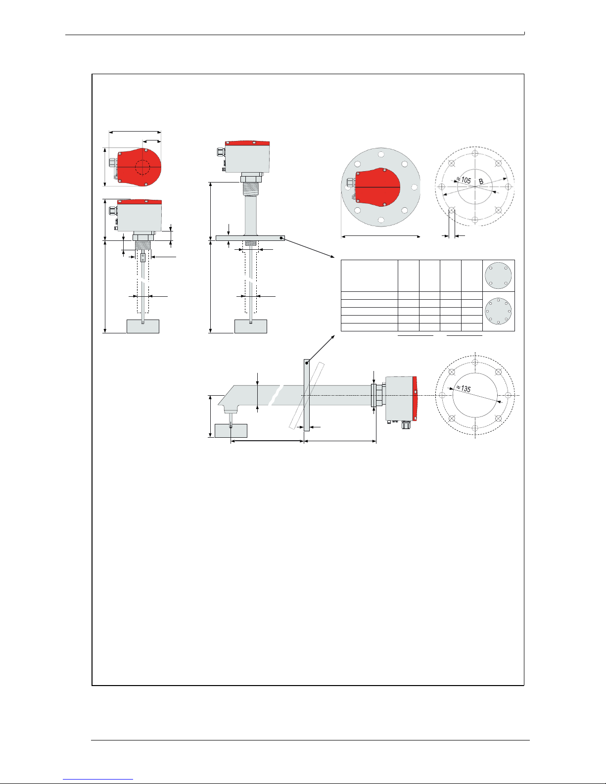
7.5 Dimensions
160
58
A
41
C
48
G1½"
A B C D
33.2 33.2
mm
L: Eintauchtiefe
L
D
220
Page 13
MBA200
·
Operating Instructions 8011417 V 2.2
·
© MBA Instruments GmbH Germany 12
Bin-levellndicator MBA2CO
7.6
EC-Type Examination Certificate
Page 1 of
2
Page 14

Bin-level Indicator MBA200
Notes
Page 15

8011417 ( 2.2) · 2015-10
MBA200
MBA Instruments GmbH
Friedrich-List-Straße 7
25451 Quickborn
Germany
Phone +49 4106/123 88-80
www.mba-instruments.de
[email protected]
 Loading...