

Mazi HDVR-0410H, HDVR-0820H, HDVR-1640H Operation Manual

Digital Video Recorder
Quick Operation Guide
UD.6L0202B1345A02

Quick Operation Guide of Digital Video Recorder
1
TABLE OF CONTENTS
DVR Pre-Installation ....................................................................................................................................... 2
DVR Installation .............................................................................................................................................. 2
Hard Disk Installation ..................................................................................................................................... 2
Front Panels ...................................................................................................................................................... 4
Rear Panels ....................................................................................................................................................... 8
Peripheral Connections ................................................................................................................................. 10
Wiring of Alarm Input ........................................................................................................................... 10
Wiring of Alarm Output ........................................................................................................................ 10
Alarm Connection .................................................................................................................................... 10
RS-485 and Controller Connection .......................................................................................................... 11
Termination Switch Operation ................................................................................................................. 12
Specifications .................................................................................................................................................. 13
Table 1 Specification for 4-ch & 8-ch HDVR .......................................................................................... 13
Table 2 Specification for HDVR-1640H .................................................................................................. 14
HDD Storage Calculation Chart ................................................................................................................... 16
Accessing by Web Browser ............................................................................................................................ 17
Logging In ................................................................................................................................................ 17
Live View ................................................................................................................................................. 17
Recording ................................................................................................................................................. 19
Playback ................................................................................................................................................... 20
Log 21
Menu Operation ............................................................................................................................................. 22
Menu Structure ......................................................................................................................................... 22
Startup and Shutdown .............................................................................................................................. 22
Live View ................................................................................................................................................. 23
Record Settings ........................................................................................................................................ 23
Instant Recording ............................................................................................................................. 24
All-day Recording ............................................................................................................................ 24
Playback ................................................................................................................................................... 24
Backup ..................................................................................................................................................... 25
Quick Operation Guide of Digital Video Recorder
2
Thank you for purchasing our product. If there is any question or request, please do not hesitate to contact dealer.
DVR Pre-Installation
Please take into consideration the following precautionary steps before installation of the DVR.
1. Keep all liquids away from the DVR.
2. Install the DVR in a well-ventilated and dust-free area.
3. Ensure environmental conditions meet factory specifications.
4. Install a manufacturer recommended HDD.
DVR Installation
During the installation of the DVR:
1. Use brackets for rack mounting.
2. Ensure there is ample room for audio and video cables.
3. When installing cables, ensure that the bend radius of the cables are no less than five times than its diameter.
4. Connect both the alarm and RS-485 cable.
5. Allow at least 2cm (~0.75-inch) of space between racks mounted devices.
6. Ensure the DVR is grounded.
7. Environmental temperature should be within the range of -10 ºC ~ 55 ºC , 14ºF ~ 131ºF.
8. Environmental humidity should be within the range of 10% ~ 90%.
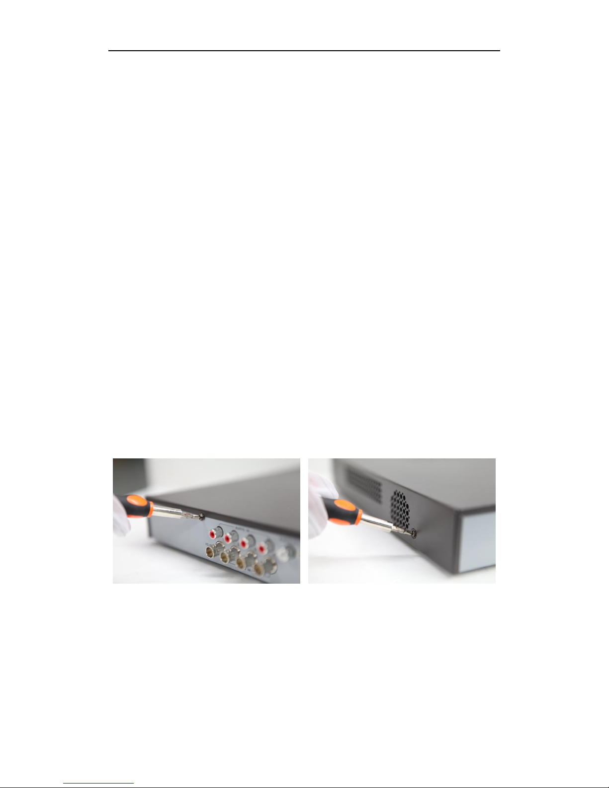
Hard Disk Installation
Before you start:
Before installing a hard disk drive (HDD), please make sure the power is disconnected from the DVR. A factory
recommended HDD should be used for this installation.
Up to 8 SATA hard disks can be installed on your DVR.
Tools Required: Screwdriver.
Steps:
1. Remove the cover from the DVR by unfastening the screws on the back and side.
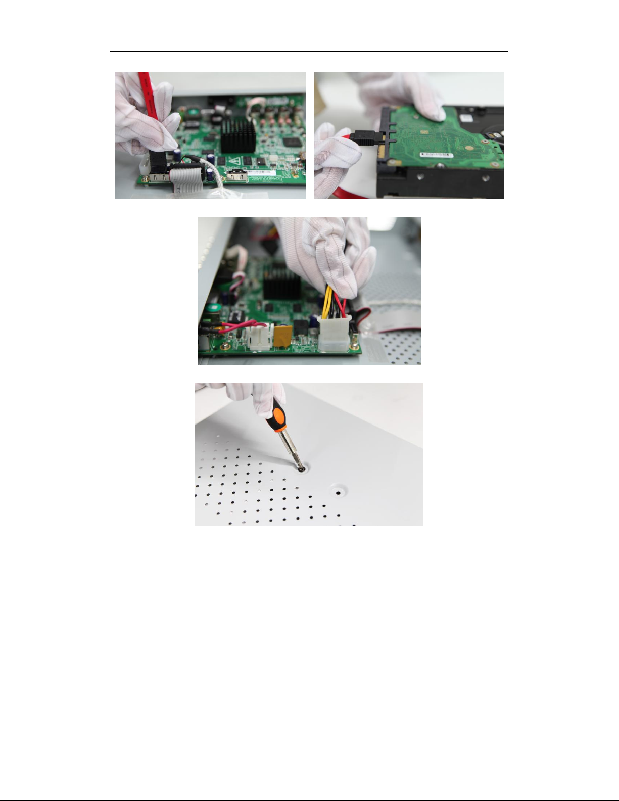
2. Connect one end of the data cable to the motherboard of DVR and the other end to the HDD.
Quick Operation Guide of Digital Video Recorder
3
3. Connect the power cable to the HDD.
4. Place the HDD on the bottom of the device and then fasten the screws on the bottom to fix the HDD.
5. Re-install the cover of the DVR and fasten screws.
Quick Operation Guide of Digital Video Recorder
4
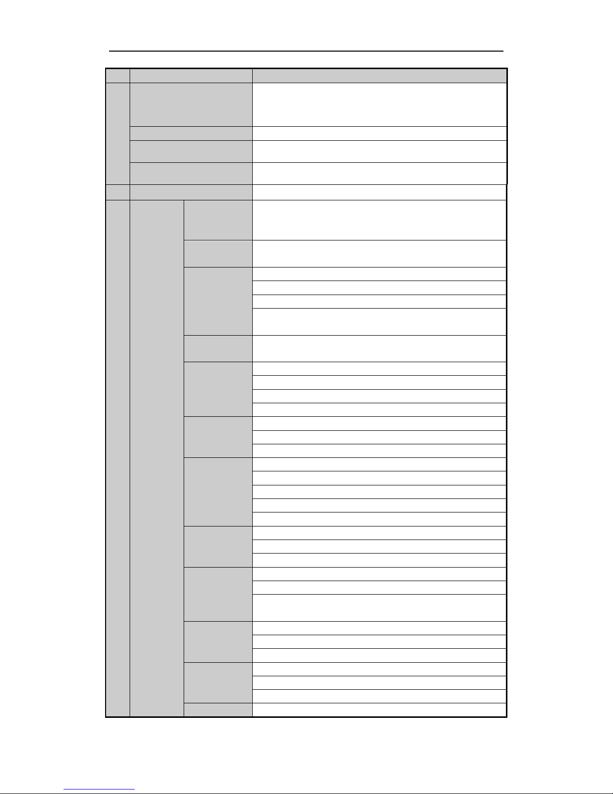
Front Panels
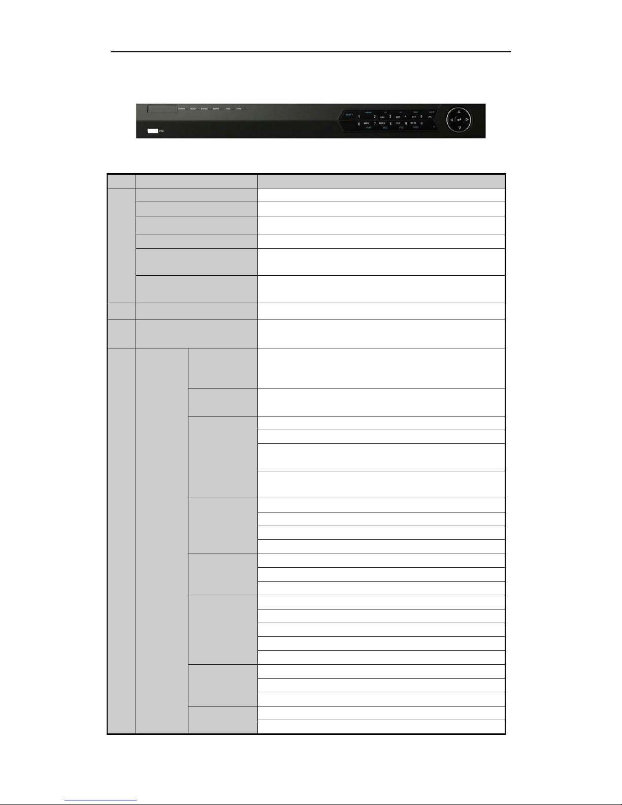
Front Panel of HDVR-xxx0H
Description of Control Panel Buttons
No.
Name
Function Description
1
POWER
Power indicator turns yellow once the power switch turns on.
READY
Ready indicator turns yellow when system is running.
STATUS
Status indicator turns red when SHIFT mode is on.
ALARM
Alarm indicator turns red when a sensor alarm is detected.
HDD
HDD indicator blinks red when data is being read from or written to
HDD.
TX/RX
TX/RX indictor blinks yellow when network connection is
functioning properly.
2
IR Receiver
Receiver for IR remote.
3
USB Interface
Universal Serial Bus (USB) ports for additional devices such as
USB mouse and USB Hard Disk Drive (HDD).
4
Composite
Keys
SHIFT
Switch between the numeric or letter input and functions of the
composite keys. (Input letter or numbers when the light is out;
Realize functions when the light is red.)
1/MENU
Enter numeral “1”;
Access the main menu interface.
2/ABC/F1
Enter numeral “2”;
Enter letters “ABC”;
The F1 button when used in a list field will select all items in the
list.
In PTZ Control mode, it will turn on/off PTZ light and when the
image is zoomed in, the key is used to zoom out.
3/DEF/F2
Enter numeral “3”;
Enter letters “DEF”;
The F2 button is used to change the tab pages.
In PTZ control mode, it zooms in the image.
4/GHI/ESC
Enter numeral “4”;
Enter letters “GHI”;
Exit and back to the previous menu.
5/JKL/EDIT
Enter numeral “5”;
Enter letters “JKL”;
Delete characters before cursor;
Check the checkbox and select the ON/OFF switch;
Start/stop record clipping in playback.
6/MNO/PLAY
Enter numeral “6”;
Enter letters “MNO”;
Playback, for direct access to all-day playback interface.
7/PQRS/REC
Enter numeral “7”;
Enter letters “PQRS”;
Quick Operation Guide of Digital Video Recorder
5
No.
Name
Function Description
Open the manual record interface.
8/TUV/PTZ
Enter numeral “8”;
Enter letters “TUV”;
Access PTZ control interface.
9/WXYZ/PREV
Enter numeral “9”;
Enter letters “WXYZ”;
Multi-channel display in live view.
0/A
Enter numeral “0”;
Shift the input methods in the editing text field.(Upper and
lowercase, alphabet, symbols or numeric input).
5
DIRECTION
The DIRECTION buttons are used to navigate between different
fields and items in menus.
In the Playback mode, the Up and Down button is used to speed up
and slow down recorded video. The Left and Right button will select
the next and previous record files.
In Live View mode, these buttons can be used to cycle through
channels.
In PTZ control mode, it can control the movement of the PTZ
camera.
ENTER
The ENTER button is used to confirm selection in any of the menu
modes.
It can also be used to tick checkbox fields.
In Playback mode, it can be used to play or pause the video.
In single-frame Playback mode, pressing the button will advance the
video by a single frame.
In Auto-switch mode, it can be used to stop /start auto switch.
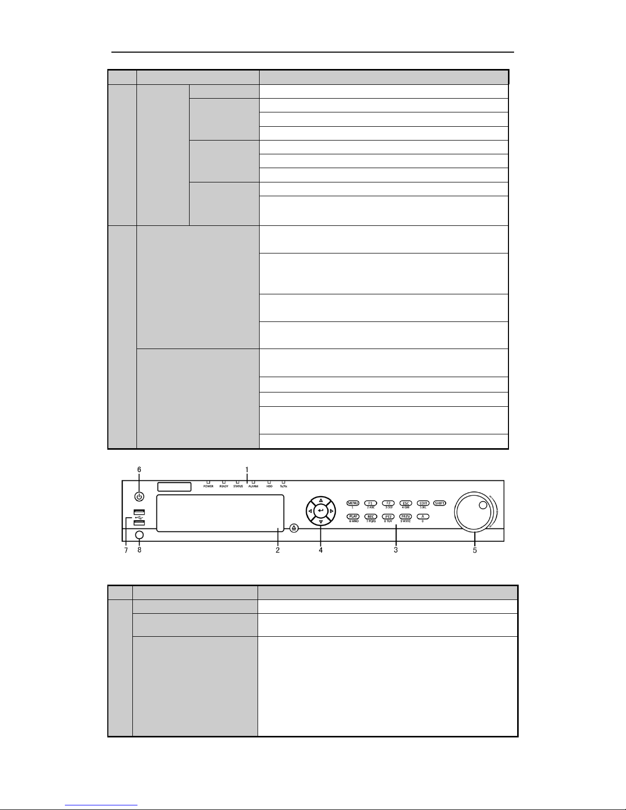
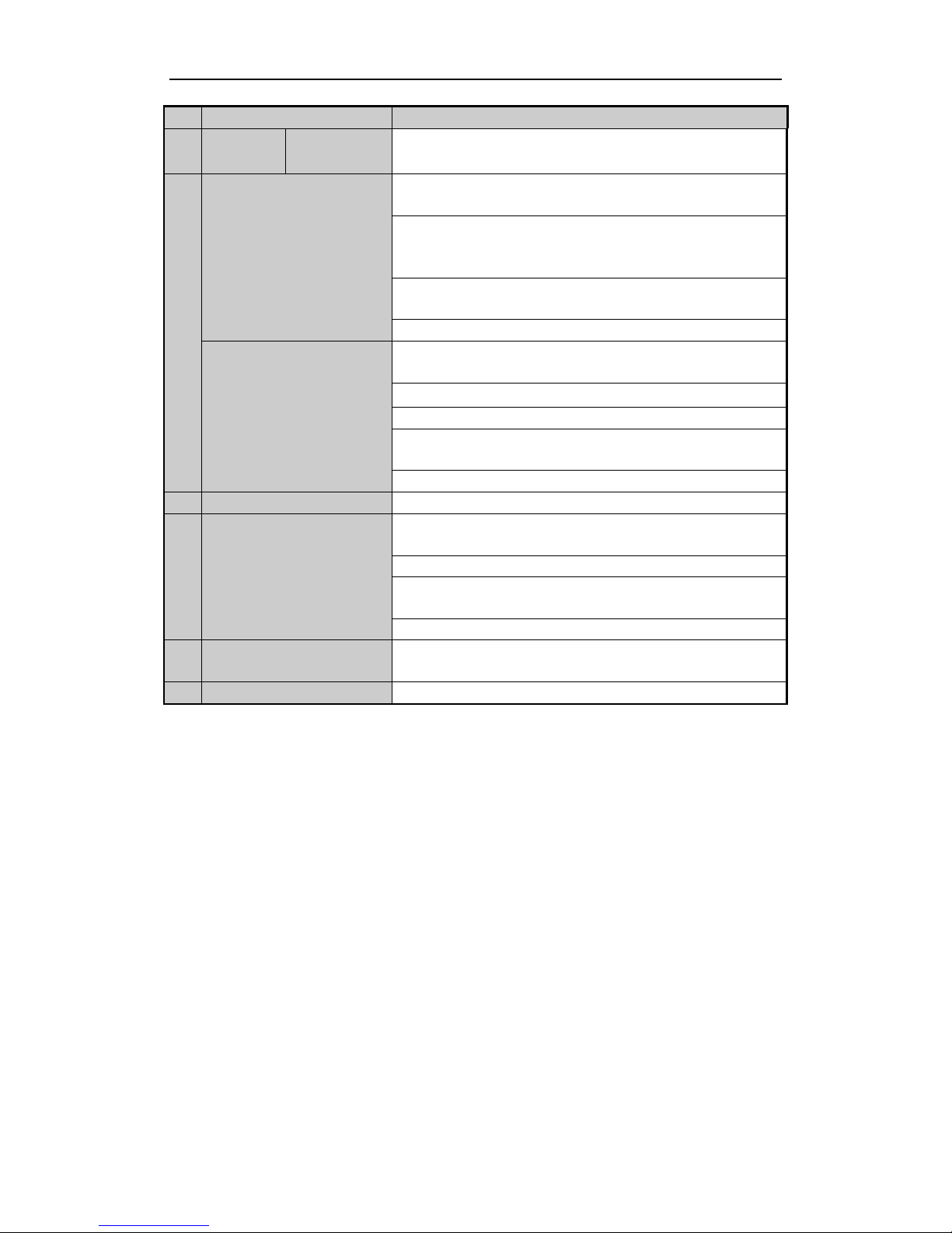
Front Panel of HDVR-1640H
Description of Front Panel
No.
Name
Function Description
1
POWER
Power indicator lights in green when DVR is powered up.
READY
Ready indicator is normally green, indicating that the DVR is
functioning properly.
STATUS
Indicator turns green when DVR is controlled by an IR remote control
with the address from 1~254;
Indicator turns red when the SHIFT button is used;
Indicator does not light when the DVR is controlled by a keyboard or
by the IR remote control with the address of 255;
Indicator turns green when the DVR is controlled by IR remote control
(with the address from 1~254) and keyboard at the same time , and the
SHIFT button is not used;
Indicator turns orange : (a) when the DVR is controlled by IR remote
Quick Operation Guide of Digital Video Recorder
6
No.
Name
Function Description
control (with the address from 1~254) and keyboard at the same time
and the SHIFT button is used as well; (b) when the DVR is controlled
by IR remote control (with the address from 1~254) and the SHIFT
button is used.
ALARM
Alarm indicator turns red when a sensor alarm is detected.
HDD
HDD indicator blinks in red when data is being read from or written to
HDD.
TX/RX
TX/RX indictor blinks in green when network connection is
functioning properly.
2
DVD-R/W
Slot for DVD-R/W.
3
Composite
Keys
SHIFT
Switch between the numeric or letter input and functions of the
composite keys. (Input letter or numbers when the light is out; Realize
functions when the light is red.)
1/MENU
Enter numeral “1”;
Access the main menu interface.
2/ABC/F1
Enter numeral “2”;
Enter letters “ABC”;
The F1 button when used in a list field will select all items in the list.
In PTZ Control mode, it will turn on/off PTZ light and when the image
is zoomed in, the key is used to zoom out.
In live view or playback mode, the F1 button can be used to switch
between main and spot video output.
3/DEF/F2
Enter numeral “3”;
Enter letters “DEF”;
The F2 button is used to change the tab pages.
In PTZ control mode, it zooms in the image.
4/GHI/ESC
Enter numeral “4”;
Enter letters “GHI”;
Exit and back to the previous menu.
5/JKL/EDIT
Enter numeral “5”;
Enter letters “JKL”;
Delete characters before cursor;
Check the checkbox and select the ON/OFF switch;
Start/stop record clipping in playback.
6/MNO/PLAY
Enter numeral “6”;
Enter letters “MNO”;
In Playback mode, it is used for direct access to playback interface.
7/PQRS/REC
Enter numeral “7”;
Enter letters “PQRS”;
Manual record, for direct access to manual record interface; manually
enable/disable record.
8/TUV/PTZ
Enter numeral “8”;
Enter letters “TUV”;
Access PTZ control interface.
9/WXYZ/PREV
Enter numeral “9”;
Enter letters “WXYZ”;
Multi-channel display in live view.
0/A
Enter numeral “0”;
Quick Operation Guide of Digital Video Recorder
7
No.
Name
Function Description
Shift the input methods in the editing text field. (Upper and lowercase,
alphabet, symbols or numeric input).
4
DIRECTION
The DIRECTION buttons are used to navigate between different fields
and items in menus.
In the Playback mode, the Up and Down button is used to speed up and
slow down recorded video. The Left and Right button will select the
next and previous record files.
In Live View mode, these buttons can be used to cycle through
channels.
In PTZ control mode, it can control the movement of the PTZ camera.
ENTER
The ENTER button is used to confirm selection in any of the menu
modes.
It can also be used to tick checkbox fields.
In Playback mode, it can be used to play or pause the video.
In single-frame Playback mode, pressing the button will advance the
video by a single frame.
In Auto-switch mode, it can be used to stop /start auto switch.
5
POWER
Power on/off switch.
6
JOG SHUTTLE Control
Move the active selection in a menu. It will move the selection up and
down.
In Live View mode, it can be used to cycle through different channels.
In the Playback mode, it can be used to jump 30s forward/backward in
video files.
In PTZ control mode, it can control the movement of the PTZ camera.
7
USB Interface
Universal Serial Bus (USB) ports for additional devices such as USB
mouse and USB Hard Disk Drive (HDD).
8
IR Receiver
Receiver for IR remote control.
Quick Operation Guide of Digital Video Recorder
8
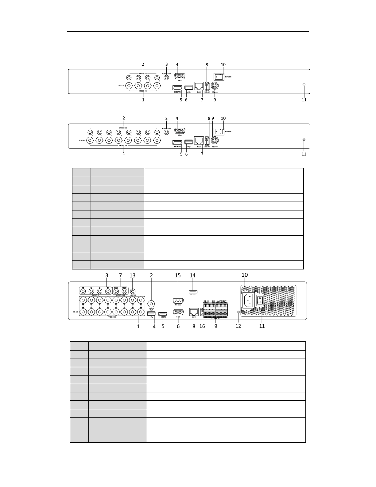
Rear Panels
HDVR-0410H
HDVR-0820H
No.
Item
Description
1
VIDEO IN
HD-SDI interface for video input.
2
AUDIO IN
RCA connector
3
AUDIO OUT
RCA connector
4
VGA
DB15 connector for VGA output. Display local video output and menu.
5
HDMI
HDMI video output connector.
6
USB Port
Universal Serial Bus (USB) port for additional devices.
7
Network Interface
Connector for network
8
RS-485 Interface
Connector for RS-485 devices.
9
Power Supply
DC 12V power supply.
10
Power Switch
Switch for turning on/off the device.
11
GND
Ground
HDVR-1640H
No.
Item
Description
1
VIDEO IN
HD-SDI interface for video input.
2
VIDEO OUT
BNC connector for video output.
3
AUDIO IN
RCA connector
4
USB Port
Universal Serial Bus (USB) port for additional devices.
5
HDMI
HDMI video output connector.
6
VGA
DB15 connector for VGA output. Display local video output and menu.
7
AUDIO OUT
RCA connector
8
Network Interface
Connector for network
9
RS-485 Interface
Connector for RS-485 devices. T+ and T- pins connect to R+ and R- pins
of PTZ receiver respectively.
D+, D- pin connects to Ta, Tb pin of controller. For cascading devices,
 Loading...