

Page 1
GENUINE Mazda Mobile Start
INSTALLATION INSTRUCTIONS
Thank you for purchasing a genuine Mazda accessory.
Before removal and installation, be sure to thoroughly read these instructions. Please read the contents of this
booklet in order to properly install and use the Mazda Mobile Start. Your safety depends on it.
Keep these instructions with your vehicle records for future reference.
WARNING
There are several WARNING and CAUTION sections in this booklet concerning safety when installing or
•
removing the Mazda Mobile Start. Always read and follow them in order to prevent injuries, accidents, and possible
damage to the vehicle.
WARNING: Indicates a situation in which serious injury or death could result if the warning is ignored.
CAUTION: Indicates a situation in which bodily injury or damage to the vehicle could result if the caution is ignored.
• For areas indicating the tightening torque in this instruction manual, tighten to the specified torque using a torque wrench. For
areas in which the tightening torque is indicated inside parentheses ( ), the tightening torque is indicated as a reference value,
however tightening using a torque wrench is not necessary.
• Do not modify the Mazda Mobile Start.
• Do not install the Mazda Mobile Start in any way other than described in the following instructions.
• If in any doubt, please ask your Mazda dealer to install the accessory in order to prevent errors in installation.
• If you have any questions about the use of the accessory, ask your Mazda dealer for proper advice before using it.
• Mazda and its suppliers are not responsible for injuries, accidents, and damage to persons and property that arise from the
failure of the dealer or installer to follow these instructions.
• To ensure safety and reliability of the work, installation, removal and disposal work must be carried out by an Authorized
Mazda Dealership.
• Be careful not to lose removed parts, and be sure that they are kept free from scratches, grease or other dirt.
PART NUMBER :
NOTE
To the dealer
Please turn over these instructions to the customer after installation.
•
To the customer
Keep these instructions after installation. The instructions may be necessary for
•
installing other optional parts or removal of this accessory.
Should the vehicle or this accessory be resold, always leave these instructions
•
with it for the next owner.
PART NAME :
VEHICLE :
Mazda Mobile Start (MMS)
Mazda 6
0000-8F-Z80 (MMS ECU Kit)
0000-8F-H28 (MMS Harness Kit)
[KD53-V7-629 (Hood Switch)]
1
090003-33260700
Page 2
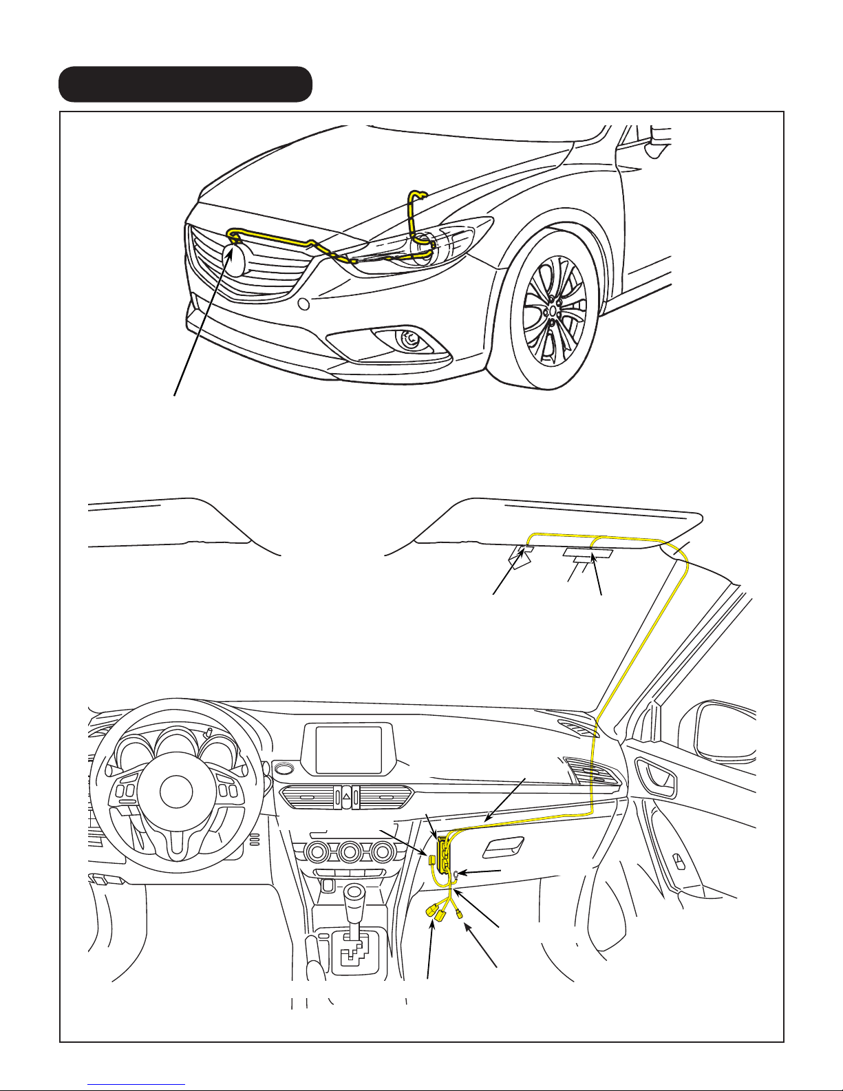
1. INSTALLATION VIEW
(Sold separately) Hood switch
(Only for vehicles without theft-deterrent or without i-ELOOP system)
GPS & TEL Antenna Cables
MMS 2P Connector
RES Diagnostic Connectors
GPS Antenna
MMS ECU
TEL Antenna
Harness (GND)
MMS Harness
LED Connector
2
Page 3
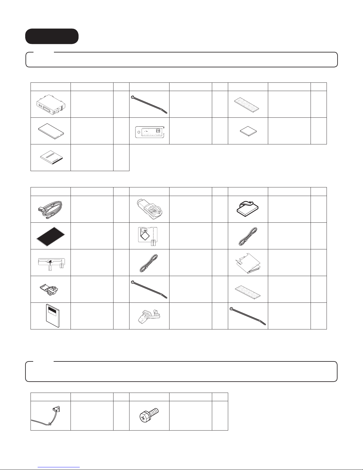
2. PARTS
Note
• Verify that the kit includes all the following parts and that they are free of dirt, scratches, or damage.
MMS ECU KIT (Part no. 0000-8F-Z80)
Part Part Name Qty. Part Part Name Qty. Part Part Name Qty.
MMS ECU
Double-sided
adhesive tape
(25 x 69mm)
Owner's Manual
1
1
1
Wire Tie
(White 200mm)
MMS Key Tag
: Part marked with a star mark is not used for this vehicle.
«
5
1
Urethane
Foam tape
(35 x 115mm)
«
Double-sided
adhesive tape
(25 x 25mm)
HARNESS KIT (Part no. 0000-8F-H28)
Part Part Name Qty. Part Part Name Qty. Part Part Name Qty.
MMS Harness
FH Protection
Sheet
TEL Film
Antenna
1
1
1
LED
GPS Film
Antenna
TEL Antenna
Cable
1
1
1
«
Harness Clamp
GPS Antenna
Cable
Antenna
Template
2
3
2
1
1
«
Electro tap
Installation
Instructions
(ENG/SPA/FRE)
: Parts marked with a star mark are only used on vehicles without theft-deterrent or without i-ELOOP system.
«
1
3
Wire Tie
(White 200mm)
A-Pillar Clip
(D651-68-162A)
15
1
Urethane
Foam tape
(35 x 115mm)
«
Wire Tie
(Black 200mm)
(Sold separately) The following parts are also necessary for installation.
Note
• These parts are not necessary for vehicles with theft-deterrent or with i-ELOOP system because the hood
switch is already equipped.
HOOD SWITCH KIT (Part no. KD53-V7-629)
Part Part Name Qty. Part Part Name Qty.
Hood switch
1
Screw
1
2
10
3
Page 4
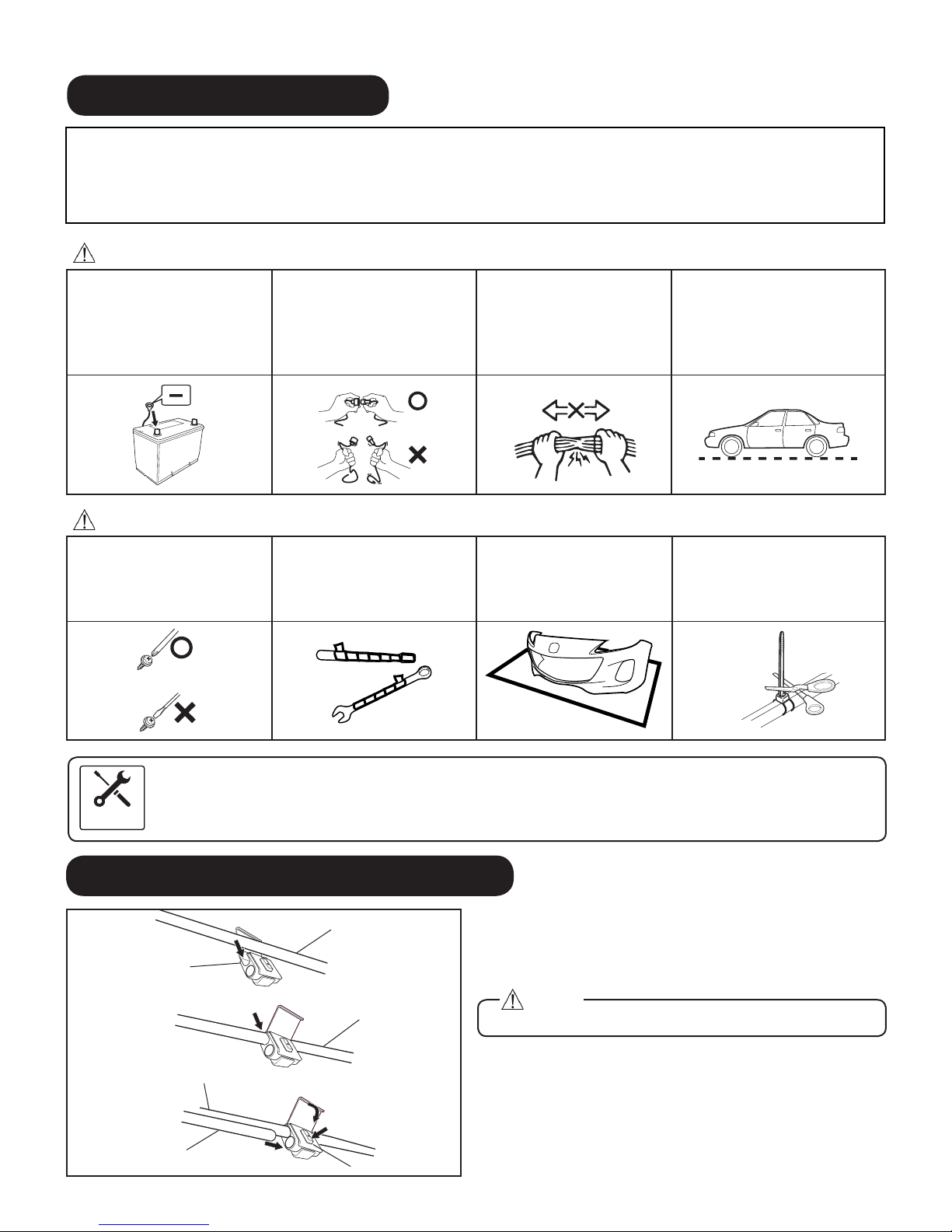
3. BEFORE INSTALLATION
WORKSHOP
MANUAL
REQUIRED TOOLS
• 10mm Socket Wrench • Scissors • Torque Wrench • Taped Flathead Screwdriver • Mat
• Electrical Tape • Panel Removal Tool • Soft clean cloth • Squeegee • Glass Cleaner • Nipper
• Pliers • Primer (3M Promoter-4298) • IPA (Isopropyl alcohol) • Phillips Screwdriver
WARNING
When the negative battery cable
is connected during operation, it
may cause electric shock or other
personal injuries. Disconnect the
negative battery cable before
removal/installation.
When connecting or disconnecting
connectors, grasp the connectors,
not the wires. Otherwise a short,
an accident from poor contact or
re may occur.
Do not pull the harness with
excessive force. Doing so can
cause a breakage or a shortrelated accident, as well as an
electrical short or re.
Park the vehicle on a level ground.
Set the vehicle on park (P) and
apply the parking brake. Be sure to
turn the ignition switch off, otherwise
the vehicle can move, causing
personal injury or vehicle damage.
CAUTION
Using improper tools may cause
damage and or broken parts.
Use the correct tool for the job.
Wrap protective tape around
screwdrivers and fastener
removal tools to prevent
scratching the vehicle.
Put the removed parts and the
parts in the kit on the protective
sheet to prevent scratches.
Excessive length of wire tie may
interfere with other parts and
cause damage. Cut unnecessary
part up to about 5 mm {0.19 in}
from the xed point.
• When the negative battery cable is removed, the clock, radio, trip meters and other memories will be erased.
Make sure to record the content of the memory.
• Refer to the Workshop Manual for removal and installation of vehicle parts. Not following the procedures for
removal/installation in the Workshop Manual could result in an accident or vehicle malfunction.
4. CONNECTION USING ELECTRO-TAP
Vehicle wiring harness
1
Electro tap
2
Vehicle wiring harness
Harness
3
Vehicle wiring harness
5
Lock
4
Firmly press using pliers
Terminal
Branch connection procedure using electro tap.
1. Insert the vehicle wiring harness into the electro tap.
2. Fold the electro tap as shown in the gure and lock it.
Caution
• Firmly engage the lock part until a click sound is heard.
3. Insert the harness to the end of the electro tap.
4. Firmly press the electro tap terminal using pliers.
5. Fold the electro tap in the direction of the arrow shown in
the gure and lock it.
4
Page 5
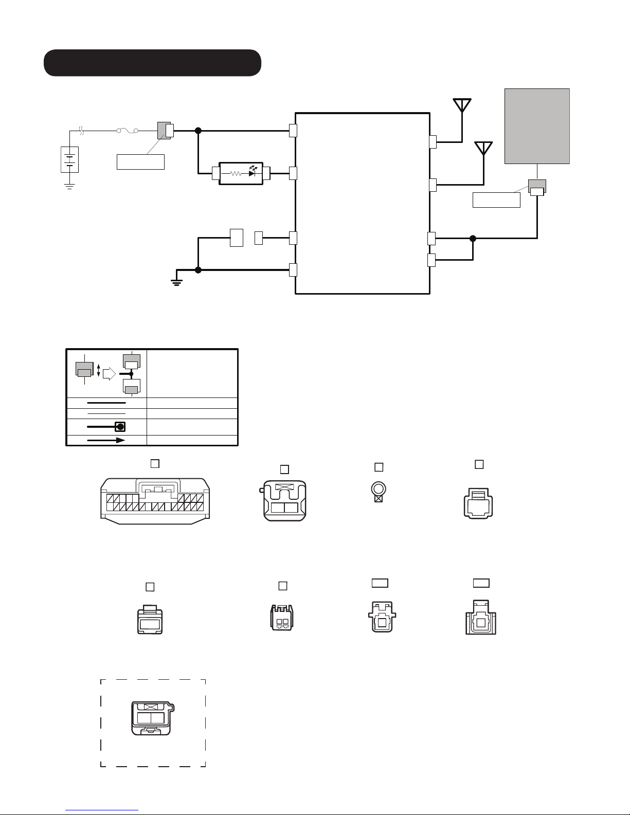
5. CONNECTION DIAGRAM
GPS
20XX-
CONNECTORS
MAZDA MOBILE START (MMS)MMSMAZDA
ROOM
Battery
Pre connector
Pin : 1
B1
RES LED
F2
RES Connector
ANTENNA
SSU
(Start
/
+B
A10
F1
LED
A5
MMS ECU
E1
D1
RDIG
A16
GPS
GPS
TEL
TEL
STX
A4
TEL
ANTENNA
Pre connector
Stop
control Unit)
Pin:2
B2
VEHICLE
CONNECTOR
10
GND (M6)
C1
**
Connector to Connector
**
MMS Wire
Vehicle Wire
Scotch lock connection
MMS or Vehicle Terminal Insert
A
5
34
16 19
(FEMALE PIN)
B
21
(
FEMALE PIN
SRX
GND
A19
A3
C
(TERMINAL PIN)
)
D
1
(MALE PIN)
E
1
(FEMALE PIN)
VEHICLE OPTION CONNECTOR
112
(
)
MALE PIN
F
(MALE PIN)
TEL
1
(
FEMALE PIN
)
GPS
1
(
FEMALE PIN
)
5
Page 6
6. VEHICLE DISASSEMBLY
Note
• Be careful not to damage or lose any parts removed from the vehicle since they will be reused.
1. Place the vehicle in park with the parking brake engaged.
2. Disconnect negative battery terminal and wrap tape
around it to insulate.
Warning
• When the negative battery cable is connected during
operation, it may cause electric shock or personal injuries.
Disconnect the negative battery cable before removal/
installation.
Bolt tightening torque: 4.0 - 6.0 N•m (2.9 - 4.4 ft•lbf)
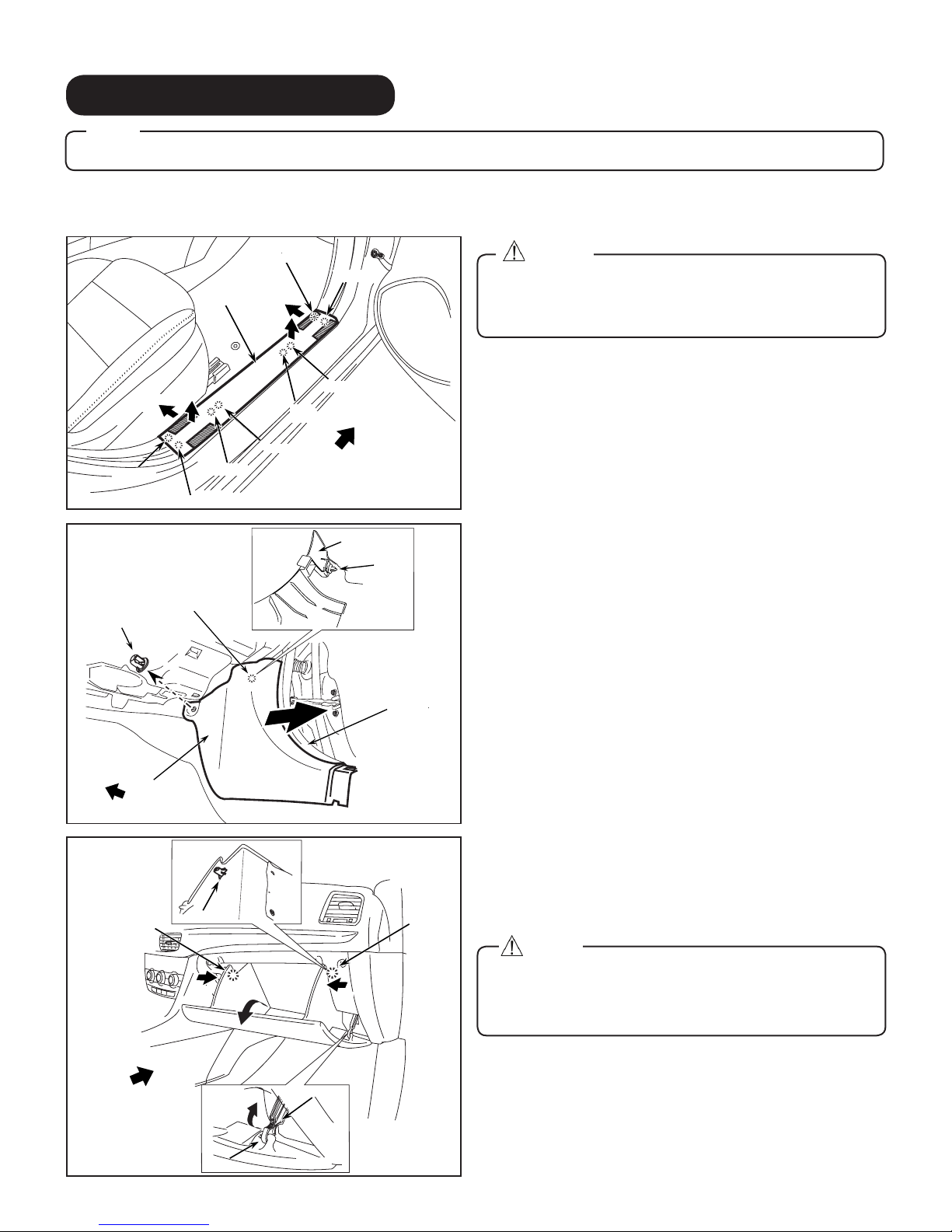
Front Scuff Plate
Tab A
Hook A
(1)
(2)
Tab B
Cap Nut
Cap Nut
Front Side Trim
Front Side Trim
Vehicle front
Vehicle front
Clip A
Pin A
Passenger side scuff plate removal
(4)
(3)
1. Use shaded area to pull (1) and lift (2) Passenger side
Front Scuff Plate to detach Tab A and Clip A.
2. Use shaded area to pull (3) and lift (4) Passenger side
Front Scuff Plate to detach Tab B and Clip B.
Passenger side front trim removal
1. Peel back the Seaming Welt.
Hook B
Clip B
Pin B
Vehicle front
Front Side Trim
Front Side Trim
(Backside)
(Backside)
Clip
Clip
2. Remove Cap Nut.
Clip
Clip
Seaming Welt
Weather strip
3. Remove Front Side trim.
Hook A
Vehicle front
Hook A
(1)
(2)
Dampener
(3)
Hook B
Glove box removal
1. Push both sides (1) and pull (2) Glove box to dislodge 2
Hooks (A).
Hook A
2. Pull (3) Dampener to detach Hook B.
Caution
• If the glove box is closed without being joined to the stay
(1)
dampener, the stay dampener may be damaged. Verify
that the stay dampener is joined to the glove box before
closing the glove box.
6
Page 7
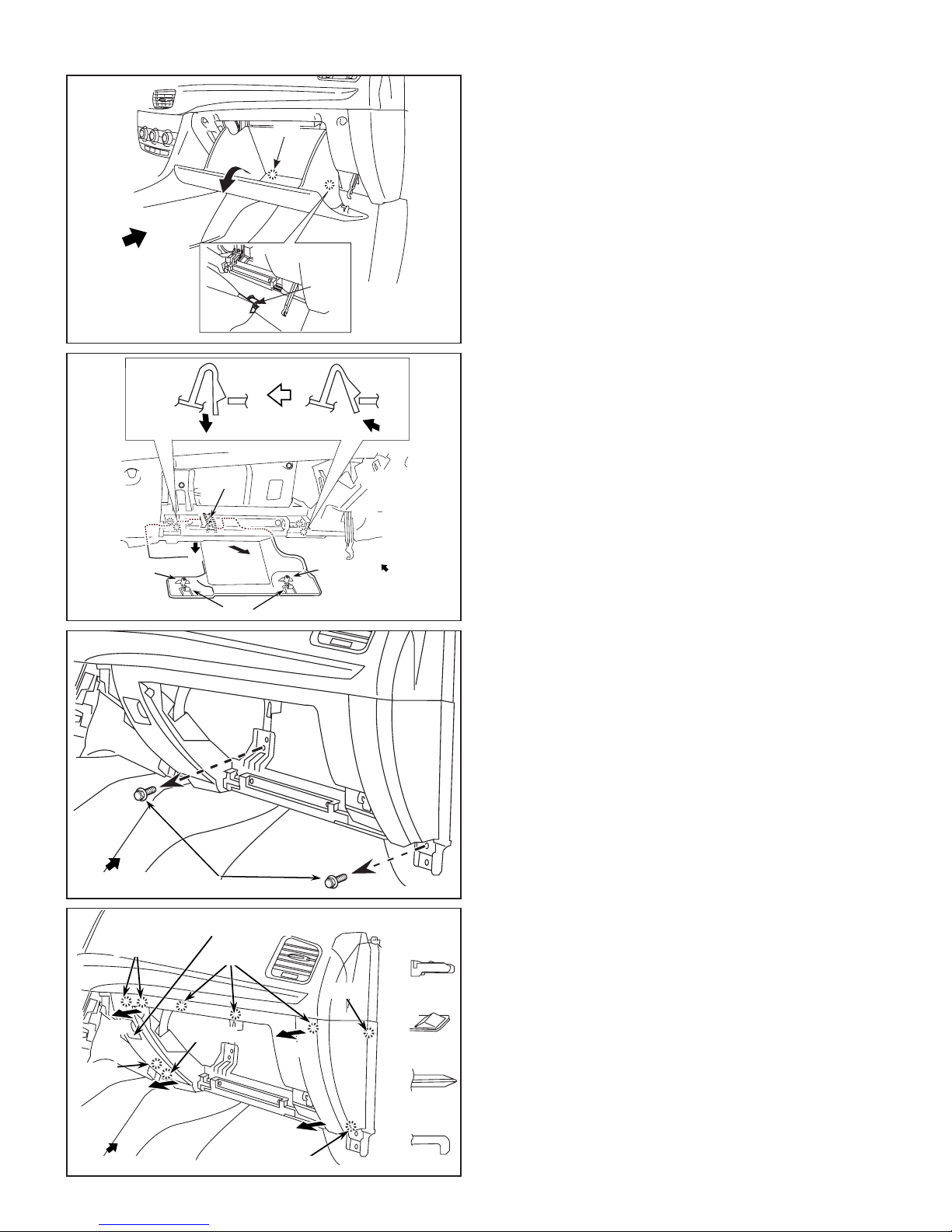
Vehicle front
3. Remove Glove box by detaching 2 bottom Hooks.
Hook
Hook
Hook A
Pin B
(2)
(2)
Guide C
(3)
Hook A
4. Remove Glove box under cover in order of arrows (1) - (3).
(1)
Pin B
Vehicle front
Passenger side lower panel removal
1. Remove 2 Bolts.
Bolt tightening torque: 2.0 - 6.0 N•m (1.5 - 4.4 ft•lbf)
Vehicle front
Vehicle Front
Clips B
Clips B
(3)
(3)
Clips B
Clips B
Vehicle Front
Vehicle front
Air Bag deactivation (PAD) switch
Bolts
Bolts
Air Bag deactivation (PAD) switch
Clips B
Clips B
Guide E
Guide E
(4)
(4)
(2)
(2)
Pin D
Pin D
(1)
(1)
Clips B
Clips B
Clips B
Clips B
Hook C
Hook C
Pin D
Pin D
Guide E
Guide E
2. Disconnect the passenger airbag deactivation (PAD)
switch connector. (Only for vehicles with passenger airbag
deactivation (PAD) switch)
3. Remove lower panel in order of arrows (1) - (4).
7
Page 8

Clip B
Clip B
Clip A
Clip A
Clip B
Clip B
A-Pillar trim removal
1. Partially peel back the seaming welt.
2. Dislodge the Passenger side A-pillar trim by pulling on the
shaded area to disengage Clip B and A.
Caution
(1)
• Do not use excessive force, A-pillar could be damaged.
Passenger Side A-Pillar
Passenger Side A-Pillar
Grommet Nipper
Grommet
Clip B
Part B
Nipper
Lead Wire
Tab
A-pillar trim
A-Pillar trim
Weather strip
Seaming welt
3. Cut the A-pillar tab wire connecting part B and the
grommet of the A-pillar tether clip.
4. Remove the A-pillar trim while detaching Guides.
A-pillar trim
A-Pillar trim
Vehicle Front
Vehicle Front
Guides
Guides
Hook
Grommet
Tape-wrapped athead screwdriver
Grommet
Grommet
Hook
Tape-wrapped at head screwdriver
A-Pillar inner panel
(1)
(1)
Tape-wrapped athead screwdriver
Front Pillar inner panel
(3)
(3)
(2)
(2)
Tape-wrapped athead screwdriver
Tape-wrapped at head screwdriver
Tape-wrapped athead screwdriver
Grommet
Grommet
5. Remove the Grommet from the A-pillar by using a flat
head screwdriver by following sequence (1) - (3).
6. Install the new supplied A-pillar tether clip into A-pillar
before proceeding.
Caution
• Ensure the new supplied tether clip is used in step 6.
8
Page 9

7. HOOD SWITCH INSTALLATION
Note
• This procedure is not necessary for vehicles with Theft-deterrent System or with i-ELOOP system because the
hood switch is already installed.
Fastener
Flathead screwdriver
Guides
Set plate
Fastener
Vehicle Front
Hood latch cover
1. Remove 2 Fasteners from the Vehicle Set Plate.
2. Remove the Vehicle Set Plate.
3. Remove the Hood Latch Cover.
Flathead scredriver insertion slot
(1)
Tab
Hood l atch
Main fuse cover
Main fuse cover
Tab
Tab
Vehicle Front
Vehicle Front
(2)
Tab
Vehicle Front
Hood l atch
4. Remove the Main Fuse cover.
9
Page 10

Fresh air duct
Bolts
5. Remove 2 Bolts from the Fresh air duct.
Bolt tightening torque: 7.8 - 10.8 N•m (5.7 - 7.9 ft•lbf)
Vehicle Front
Fresh air duct
Fastener Grille bracket
Fastener
Screw
Screw
6. Lift Fresh Air duct to remove Fastener.
7. Remove 1 Fastener and 2 Screws.
Screw tightening torque: 4.0 - 9.8 N•m (2.9 - 5.8 ft•lbf)
Vehicle Front
Hood Latch
Hood Switch
Vehicle front
8. Install the Hood switch to the Hood Latch and secure it
using the supplied Screw.
Screw
10
Page 11

Vehicle front
Vehicle front
Do not let hood switch harness
make contact with bolt
Harness Clamp
Hood switch harness
Upper Shroud member
Upper shroud member
Bolt
Wire Tie (Black)
Harness Clamp
Vehicle Front
Hood switch harness
Hood switch harness
9. Hook the Hood switch harness to the Hood latch and
secure it using a wire tie (black).
10. Peel the tape backings from the harness clamps and afx
them on the upper shroud member on 2 locations.
Caution
• Clean attachment surface using isopropyl alcohol and
cleaning towel.
11. Route the hood switch harness and secure them to the 2
harness clamps. Press firmly on clamp tabs to ensure
secure retention of hood switch harness.
12. Route the Hood switch harness between the Grille bracket
and the upper shroud member.
Grille bracket
Grille bracket
Hood switch harness
Hood Switch Harness
Pass behind vehicle
Pass behind vehicle
wiring harness
wiring Harness
Wire Tie (Black)
Tie Wrap (Black)
Hood switch harness
Hood switch harness
Vehicle Front
Vehicle front
Wire Tie (Black)
Tie Wrap (Black)
Wire Tie (Black)
Tie Wrap (Black)
Vehicle wiring harness
Vehicle wiring harness
Shroud panel Vehicle front
Shroud panel
Vehicle wiring harness
Vehicle wiring harness
13. Secure the Hood switch harness to the shroud panel using
1 wire tie (black).
14. Route the Hood switch harness along the Vehicle wiring
harness and secure it with 2 wire ties (black).
Caution
• Secure the Hood switch harness on the Vehicle wiring
harness so that the hood switch harness does not contact
the vehicle edge.
15. Route the Hood switch harness along the vehicle wiring
harness and secure it with 1 wire tie (black).
Pass behind vehicle
Pass behind vehicle
wiring harness
wiring harness
Vehicle front
Vehicle front
Wire Tie (Black)
Wire tie (Black)
11
Page 12

Vehicle wiring harness
<Terminal insertion procedure>
18 pin connector
Hood switch harness (White)
<Terminal insertion procedure>
Terminal
Terminal
Retainer
Retainer
(b) Insertion terminal
Terminal
(a) Remove retainer
(c) Reinstall retainer
Terminal
[Vehicle wiring harness 18 pin connector]
(Connector viewed from wiring harness side)
Insert hood switch harness (White)
terminal to empty terminal.
Type A
Vehicle wiring harness
18 pin connector
[Vehicle wiring harness 18 pin connector]
(Connector viewed from wiring harness side)
Terminal: A (Black)
Hood switch harness (Black)
Type B
Vehicle wiring harness
18 pin connector
[Vehicle wiring harness 18 pin connector]
(Connector viewed from wiring harness side)
B
Terminal: B (Black)
Hood switch harness (Black)
Insert Terminal
Vehicle front
Hood switch harness (Black)
Electro tap and
electrical vinyl tape
Vehicle front
Hood switch harness (Black)
Electro tap and
electrical vinyl tape
Vehicle front
16. Insert the Hood switch harness (White) terminal to the
empty terminal of the Vehicle wiring harness 18 pin
connector (terminal N).
Caution
• When connecting a terminal to a connector, always refer
to the following, <Terminal insertion procedure>.
• Connect the harness terminal to the specied signal line
because a system or vehicle malfunction may occur if it
is connected incorrectly.
Vehicles with wiring harness terminal A (Black) shown in
gure (Type A)
Note
• If there is no vehicle wiring harness (Black) in the specied
position, do not perform Step 17, skip to Step 18.
17. Connect the Hood Switch harness (Black) to the vehicle
wiring harness 18 pin connector (terminal A (Black)) using
an Electro tap, and wrap the Electro tap with electrical tape.
Vehicles with wiring harness terminal B (Black) shown in
gure (Type B)
18. Branch connect the Hood Switch harness (Black) to the
vehicle wiring harness 18 pin connector (terminal B (Black))
using an Electro tap, and wrap the Electro tap using
electrical tape.
Please note caution for step 17-18 above.
Caution
• Connect the electro tap to the specied signal line because
a system or vehicle malfunction may occur if it is connected
incorrectly.
• For branch connection procedure using electro tap, refer to
[4. CONNECTION USING ELECTRO TAP] on page 4.
Hood switch harness
Wire tie (Black)
Vehicle wiring harness
19. Route the Hood Switch harness along the vehicle wiring
harness and secure it with 1 wire tie (black).
Vehicle front
12
Page 13

8. MAZDA MOBILE START INSTALLATION
Vehicle harness
2P connector
MMS ECU
Double-sided
Adhesive tape
MMS ECU
Urethane
foam tape
1. Degrease the MMS ECU using primer; apply primer only
to indicated areas where tape is attached on both sides.
Caution
• Use 3M Promoter-4298 for primer.
• When degreasing using primer, only apply primer to indicated
area to prevent other parts from becoming discolored.
• After degreasing using primer, let it dry for 1 min. or more.
2. Apply Double-sided tape on the MMS ECU.
3. Flip over the MMS ECU and apply Foam tape.
4. Detach 2 Vehicle harness clamps from the Vehicle bracket.
5. Plug in MMS harness 2P connector to Vehicle harness 2P
connector.
6. Install the MMS harness Ground terminal to the Vehicle
Ground terminal bolt.
MMS 2P
connector
Ground
location
Clamps
SIDE VIEW FRONT VIEW
Bolt tightening torque: 8.8 - 12.7 N•m (6.4 - 9.3 ft•lbf)
7. Place the MMS ECU in between the Vehicle bracket and
Vehicle harness attaching the double-sided tape on the
Vehicle bracket.
Caution
• Clean attachment surface using isopropyl alcohol and
cleaning towel.
8. Create 2 extra large wire ties by using 2 sets of 2 wire
ties, where 1 set consists of 2 wire ties (white) connected
together to create 1 extra large wire tie.
9. Secure the Vehicle harness and MMS ECU together to the
Vehicle bracket using the 2 extra large wire ties (white).
13
Page 14

10. Plug in the MMS harness 24P connector to the MMS ECU.
11. Place the Antenna template face down on the windshield
outside the vehicle, aligning the top with the headliner and
the side to the passenger side A-pillar and temporarily
secure it with electrical tape.
Antenna template
GPS Film
Antenna
Green Tab
GPS Film Antenna Backing
GPS Film Antenna Backing
Blue Tab
Green Tab
Green Tab
GPS Film Antenna
GPS Film Antenna
GPS Film Antenna
GPS Film Antenna
Headliner
Headliner
Caution
• Use glass cleaner to clean the inside windshield attachment
surface indicated by the template before attaching the GPS/
TEL Film Antennas.
12. Use the Blue tab to remove the partial protective backing
from the GPS Film Antenna.
13. From inside the vehicle, align to the edge of the headliner
and within the specified template location, attach the
partially exposed adhesive side of the GPS Film Antenna
on the Windshield.
14. Use the Green tab to slowly peel off the remaining
protective backing while using a squeegee to attach the
GPS Film Antenna on the Windshield.
Caution
• Make sure to use a squeegee when attaching the GPS Film
Antenna on the windshield to eliminate any air bubbles.
Green Tab
Green Tab
14
Page 15

Vehicle front
GPS Film Antenna
2
GPS Film Antenna
Top Protective Sticker
Top Protective Sticker
GPS Film Antenna
GPS Film Antenna
t
Top Protective Sticker
Top Protective Sticker
15. Carefully and slowly peel off the top protective sticker
leaving only the GPS Film Antenna on the Windshield.
Caution
• Do not touch the GPS Film Antenna Terminal.
After installing the GPS Film Antenna, proceed to the
next step to install the TEL Film Antenna.
TEL Film Antenna
TEL Film Antenna
TEL Film Antenna
TEL Film Antenna
No. 2 Tab
16. Use no. 1 tab to peel off the partial protective backing of
Headliner
Headliner
the TEL Film Antenna.
17. From inside the vehicle, align to the edge of the headliner
12
and within the specified template location, attach the
partially exposed adhesive side of the TEL Film Antenna
on the Windshield.
2
18. Use no. 2 tab to slowly peel off the remaining Protective
Protective Backing
Protective Backing
Squeegee
backing while using a squeegee to attach the TEL Film
Antenna on the windshield.
Squeegee
Caution
• Make sure to use a squeegee when attaching the TEL Film
Antenna on the windshield to eliminate any air bubbles.
TEL Film Antenna
TEL Film Antenna
Top Protective Sticker
Top Protective Sticker
TEL Film Antenna
TEL Film Antenna
19. Carefully and slowly peel off the Top Protective Sticker
leaving only the TEL Film Antenna on the windshield.
Caution
• Do not touch the TEL Film Antenna Terminal.
Next, proceed to install the GPS Connector.
Vehicle front
15
Page 16

G
50mm
50mm
GPS Connector
50mm
50mm
3 x 1/2 Urethane
Foam tape
50mm
50mm
20. Cut 2 urethane foam tapes into 4 pieces of 1/2 sized
urethane foam tapes.
21. Wrap the GPS Connector cable with 1/2 piece of urethane
foam tape 50mm away from the GPS Connector.
22. Wrap 2 more 1/2 pieces of urethane foam tape 50mm
away from each other.
23. Peel the protective backing off the GPS Connector.
24. Attach the GPS Connector making sure to align to the
GPS Film Antenna line guide.
Caution
• Press the GPS Connector rmly against GPS Film Antenna
Terminal.
GPS Film Antenna
50mm
50mm
Next, proceed to install the TEL Connector.
GPS Connector
25. Wrap the TEL Connector Cable with the remaining 1/2 piece
of urethane foam tape 50mm away from the TEL Connector.
TEL Connector
1/2 Urethane
Foam tape
26. Peel the protective backing off the TEL Connector.
27. Attach the TEL Connector making sure to align to the TEL
Film Antenna line guide.
TEL Film Antenna
Caution
• Press the TEL Connector rmly against TEL Film Antenna
Terminal.
TEL Connector
16
Page 17

Vehicle Headliner
TEL Antenna Cable
GPS Connector Cable
28. Tuck both Antenna cables in between the headliner and
the windshield routing them toward the passenger side
A-pillar area.
GPS & TEL Antenna Cables
4 x Wire Ties
(White)
1/2 FH Protection sheet
29. Route the Antenna cables down the passenger side A-pillar
and secure to the vehicle harness using 4 wire ties (white).
Caution
• Ensure that Antenna cables does not interfere with airbag
operation. Do not secure wire ties to airbag or sunroof
drain tube.
Vehicle Harness
30. Cut the FH Protection sheet in half.
31. Wrap the Antenna cables starting from the bottom of the
A-pillar using the 2 pieces of 1/2 FH Protection sheet.
32. Secure the FH Protection sheet using electrical tape.
1/2 FH Protection sheet
GPS & TEL Antenna Cables
Vehicle right
33. Route both GPS & TEL Antenna Cables down towards the
Glove box area.
17
Page 18

IP reinforcement bar
Vehicle right
GPS & TEL Antenna Cables
34. Continue routing the Antenna cables from the A-pillar
behind the IP reinforcement bar.
GPS & TEL Antenna Cables
35. Route the Antenna Cables behind the vehicle bracket
towards the MMS ECU.
Vehicle Bracket
Vehicle front
Vehicle front
IP reinforcement
bar
MMS harness
24P Connector
IP reinforcement bar
Wire Tie
(White)
GPS 1P
Connector
TEL 1P
Connector
2 x Wire Ties
(White)
MMS ECU
Wire Tie
(White)
Vehicle
harness
36. Plug in both the GPS and TEL cable 1P connectors to the
MMS ECU.
37. Secure the Antenna Cables to the vehicle IP reinforcement
bar using 1 wire tie (white).
38. Secure the Antenna Cables to the vehicle IP reinforcement
bar using 2 wire ties (white).
39. Secure the Antenna Cables to the vehicle harness using
1 wire tie (white).
GPS & TEL Antenna Cables
18
Page 19

Vehicle Harness
GPS & TEL Antenna Cables
2 x Wire Ties
(White)
40. Bundle up the excess Antenna Cables and secure to the
vehicle harness using 2 wire ties (white).
MMS Harness
41. Connect the LED to the MMS Harness 2P White connector.
Complete Section 9 {MMS Registration Procedure}
& Section 10 {MMS Check Mode} before proceeding
to Section 11 {Reinstallation/Inspection}
LED
19
Page 20

Seconds
2X
Within
10 Seconds
ON
OFF
Security Indicator
ON for 3 Seconds
OFF
Security Indicator
Flashing
OFF
Connect for
3 Seconds
ON
OFF
9. MMS REGISTRATION PROCEDURE
Make sure of the following conditions:
1. In possession of 2 Advanced Keys that are already registered to the vehicle.
2. Do not open any doors during MMS registration procedure.
Steps MMS Registration Procedure
Connect the negative battery cable and close the hood.
1
Enter vehicle's passenger side and close the door.
• MMS Harness LED lights up, wait 30 seconds until the LED light
turns off
Response
when
successful
30
Response
when it fails
Connect and disconnect the RES Diagnostic Connectors twice
within 10 seconds.
2
3
4
5
60 seconds of completion of Step 2.
Steps 3 - 6 must be completed within
• MMS Harness LED makes 2 ashes.*
If the MMS Harness LED did not ash, this procedure has failed.
• Disconnect the battery and start over from step 1.
Hold up the Advanced Key over the Start Button switch, then
press the Start Button with the Advanced Key twice to the ON
position.
• Security indicator turns ON for 3 seconds, then turns off
f Security indicator does not turn ON, this procedure has failed.
I
• Disconnect the battery and start over from step 1.
Within 4 seconds of the security indicator turning off, press the
Start Button with the Advanced Key to the OFF position.
• The Security indicator ashes.
If Security indicator does not ash, this procedure has failed.
• Disconnect the battery and start over from step 1.
Repeat steps 3 and 4 for the 2nd Advanced Key.
After both Advanced keys have been authenticated, connect the
RES Diagnostic Connectors for at least 3 seconds then disconnect.
Observe the number of ashes from the MMS Harness LED.
• MMS Harness LED ash 2 times and Start Button light will turn
6
If this procedure failed, the ignition switch stays OFF. Look at the
table below to determine the cause of failed registration.
• Check and x the cause of failed registration.
• Disconnect the battery and start over from step 1.
ON automatically for a few seconds then shuts off, indicating a
successful registration. Proceed to next section MMS Check Mode.
2X
2X
1,3,4,5,6,7
# of LED Flashes Cause of Failed Registration
1 Missed operation or step
3 3 or more Advanced Keys are already registered
4 Vehicle condition is not satised or MMS ECU is already registered (proceed to MMS Check Mode)
5 Time limit have elapsed
*If LED makes 5 ashes on step 2, refer to table above for 3 ashes.
[After a successful MMS registration, proceed to next section for MMS Check Mode]
6 Advanced Keys are not registered.
7 Communication error between MMS and SSU.
20
Page 21

r
2X
2X
2X
2X
10. MMS CHECK MODE
The following procedure is performed to verify MMS operation after MMS registration. Make sure that MMS Registration was
successful prior to proceeding.
MMS check mode preparations:
1. Place 1 Advanced Key at least 5 feet away from the vehicle and keep 1 Advanced key in your possession.
2. Enter vehicle passenger's side and leave the door open.
3. Press the hazard lights switch on the center console and take note of where the hazard light indicators are on the dash.
Turn off hazard the lights.
Steps MMS Check Mode
Disconnect Afte
10 Seconds
1
2
within 15 seconds of
completion of step 1.
Step 2 must be completed
A. Connect RES Diagnostic connectors.
B. After 10 seconds, disconnect the Diagnostic connectors
and reconnect Diagnostic connectors.
• Horn will sound 2 times.
If the Horn does not sound, this procedure has failed.
• Disconnect the Diagnostic connectors and start over.
A. Press the Start Button 3 times to switch ignition to ON and
OFF.
B. Exit the vehicle with the Advanced key and place it at least
5 feet away from the vehicle.
C. Enter the vehicle and close the door.
• Horn will sound 2 times.
• Horn will sound 2 times again before the engine starts.
If the engine does not start or horn does not sound, this
procedure has failed.
• Disconnect the Diagnostic connectors and start over from
step 1.
Response
when
successful
ON
Response
when it fails
OFF
A. Let the engine run for at least 6 seconds.
B. Disconnect the Diagnostic connectors and observe
3
# Hazard Flashes Meaning of Hazard Flashes
2 Check mode successful
4 Communication Module and MMS ECU connection problem
6 TEL antenna connection problem
8 GPS antenna connection problem
10 Inadequate reception problem
MMS Check mode will end if any of the following conditions are met:
1. Engine has stopped when any one of the MMS engine stop conditions is met.
2. 10 minutes have elapsed.
3. RES Diagnostic connectors are disconnected.
4. MMS check mode will end if starting engine via MMS failed.
Hazard lights for number for ash.
• Engine stops, check table below for corresponding
hazard light ashes.
21
Page 22

11. REINSTALLATION / INSPECTION
2 x Wire Ties
(White)
MMS harness
RES Diagnostic
Connectors
1. Disconnect the LED from the MMS Harness and discard.
LED
2. Secure MMS harness LED connector and ground wire to
the vehicle harness with 1 wire tie (white).
3. Secure the RES Diagnostic connectors to the vehicle
harness with 1 wire tie (white).
Lower panel (Passenger's side)
Glove compartment
Standard value: 0.5-2.5mm
Standard value: 0.5-2.5mm
Vehicle Harness
4. Reinstall parts in the reverse order of the installation
procedure [Section 6 Vehicle Disassembly].
5. After installing the passenger's side lower panel and glove
compartment, measure the clearance, and verify that the
measurement value is within the specication shown in
the gure.
Caution
• If the measurement value is not within the specication after
measuring the clearance between the passenger's side
lower panel and glove compartment, adjust the passenger's
side lower panel to the proper position.
6. Refer to "Required servicing after disconnection/
connecting negative battery cable" in the vehicle workshop
manual or the owner's manual to restore the vehicle
functions.
7. Attach key tag to Advanced Key.
22
Page 23

Date:
VIN:
Approved
Checked
Person in
charge
INSTALLATION
INSPECTION
SHEET
Perform the following inspections.
MAZDA 6
Mazda Mobile Start (MMS)
0000-8F-Z80 (MMS ECU Kit)
0000-8F-H28 (MMS Harness Kit)
KD53-V7-629 (Hood Switch)
WARNING
Before starting the engine, make sure there are no persons in front of or behind the vehicle, or around the engine
•
compartment. Otherwise a serious accident could result by the vehicle suddenly moving.
Do not start the engine in a place like a garage or other placer with poor ventilation. Otherwise, poisoning or asphyxation
•
could result from accumulation of axhaust gas.
Always set the wheel blocks on level ground before performing the verification.
•
1. Inspection items after installation
Verify the fitting between the vehicle part and the installed part, and inspect for damage or dirt.
•
2. Vehicle parts reinstallation
Check
Inspection Parts Inspection Items
Negative battery cable Torque check Are the battery cables securely tightened to the terminals?
Ground Torque check Is the ground bolt tightened to the proper torque?
Function restore procedure
after removal / Installation
of battery
3. Installation of accessory, operation check
Inspection Parts Inspection Items
MMS ECU Registration
Operation
Inspection Check
Have the vehicle's functions been restored by referring to "Required
servicing after disconnecting connecting negative battery cable", in
the workshop manual or the owner's manual?
Inspection Check
Has the MMS ECU been registered and checked per Section 9
(MMS Registration Procedure) and Section 10 (MMS Check Mode)
of the installation instructions?.
23
 Loading...