

Page 1
1
GENUINE PARKING SENSORS (Rear)
INSTALLATION INSTRUCTIONS
Thank you for purchasing a genuine Mazda accessory.
Before removal and installation, be sure to thoroughly read these instructions.
Please read the contents of this booklet in order to properly install and use the parking sensors
(Rear). Your safety depends on it.
Keep these instructions with your vehicle records for future reference.
There are several WARNING and CAUTION sections in this booklet concerning safety when
installing or removing the parking sensors (Rear). Always read and follow them in order to prevent
injuries, accidents, and possible damage to the vehicle.
WARNING: Indicates a situation in which serious injury or death could result if the warning
is ignored.
CAUTION: Indicates a situation in which bodily injury or damage to the vehicle could result if the
caution is ignored.
For areas indicating the tightening torque in this instruction manual, tighten to the specified torque using
a torque wrench.
Do not modify the parking sensors (Rear).
Do not install the parking sensors (Rear) remove in any way other than described in the following
instructions.
If in any doubt, please ask your Mazda dealer to install the accessory in order to prevent errors in
installation.
If you have any questions about the use of the accessory, ask your Mazda dealer for proper advice
before using it.
Mazda and its suppliers are not responsible for injuries, accidents, and damage to persons and property
that arise from the failure of the dealer or installer to follow these instructions.
To ensure safety and reliability of the work, installation, removal and disposal work must be carried out
by an Authorized Mazda Dealership.
Be careful not to lose removed parts, and be sure that they are kept free from scratches, grease or
other dirt.
PART NAME: Parking Sensors (Rear)
VEHICLE: MAZDA CX-5
PART NUMBER: KB7W V7 290A (Parking Sensors, Main Kit)
C860 V7 281A (Parking Sensors, Sensor Kit)
KD33 V7 282
(Optional ON-OFF switch)
To the dealer
Please turn over these instructions to the customer after installation.
To the customer
Keep these instructions after installation. The instructions may be necessary
for installing other optional parts or removal of this accessory.
Should the vehicle or this accessory be resold, always leave these instructions
with vehicle for the next owner.
NOTE
06DE4313B
WARNING
Page 2
2
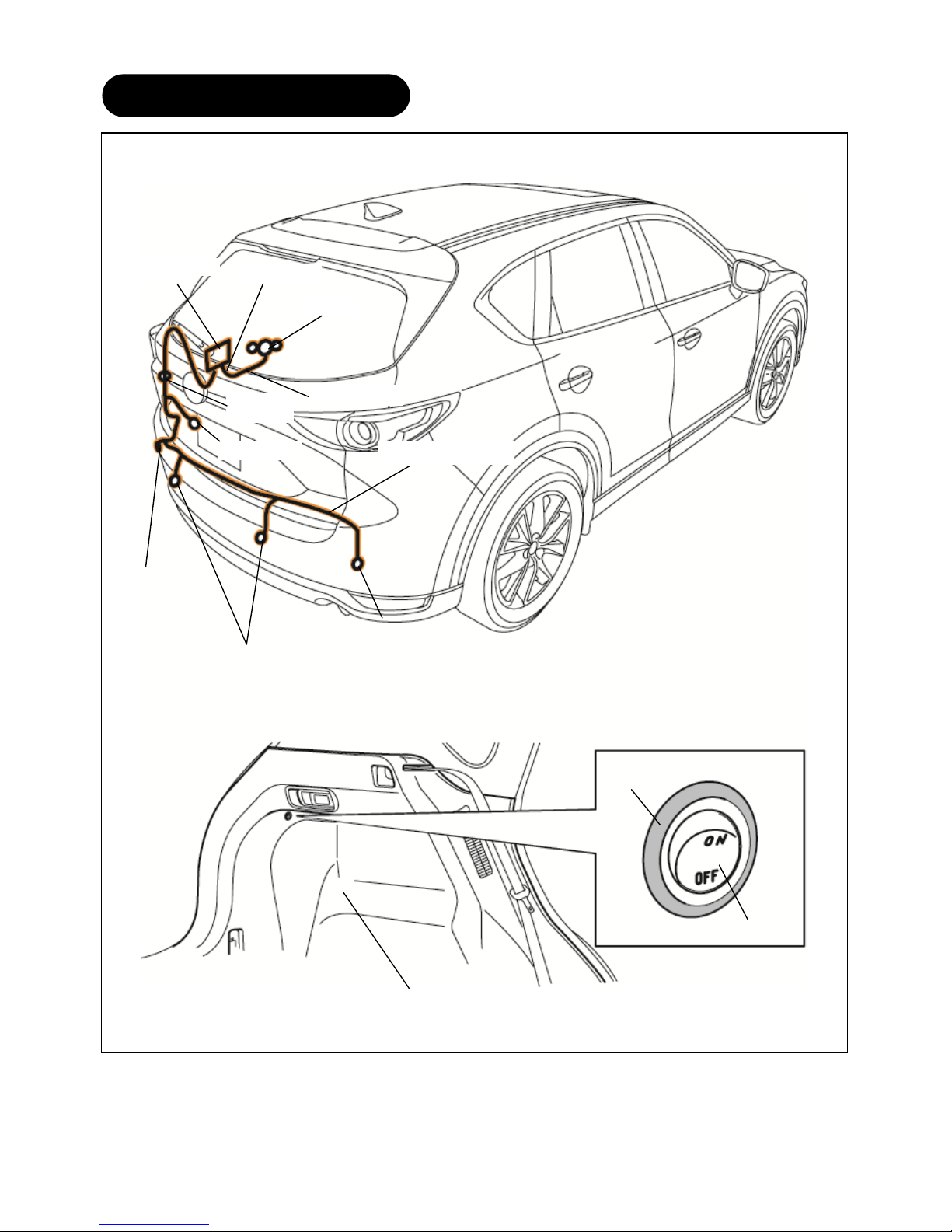
1. INSTALLATION VIEW
Back sensor
Grommet
Buzzer
Electro tap
Ground wire
Rear sensor harness
Control unit
Main harness
Rear sensor
【Optional ON-OFF switch installed】
Optional ON-OFF switch
Trunk side trim (LH)
Rear sensor
Back-up sensor ON-OFF
switch (Label)
Page 3

3
KB7W V7 290 (Parking Sensors, Main kit)
Part Part name Qty. Part Part name Qty. Part Part name Qty.
Control unit 1
Buzzer 1
Main harness 1
Electro tap 1
Mount base 9
Sensor harness
1
Tie wrap
30
Double-sided
adhesive tape
(Control unit)
1
Double-sided
adhesive tape
(Buzzer)
1
Cushioning tape
2
Grommet 1
Crump tie wrap 1
Female contact
housing
1
Installation
instructions
1
User manual 1
C860-V7-281A (Parking Sensors, Sensor kit : needed x2 sets for a vehicle)
Part Part name Qty. Part Part name Qty. Part Part name Qty.
Sensor 2
rubber
2
Sensor spacer
2
KD33-V7-282 (Optional ON-OFF switch)
Part Part name Qty. Part Part name Qty. Part Part name Qty.
Optional
ON-OFF switch
1
Harness
(With electro taps)
1
Back-up sensor
ON-OFF switch
(Label)
1
2. PARTS
Verify that the kit includes all the following parts and that the parts are not dirty, scratched, or damaged.
Note
Page 4
4
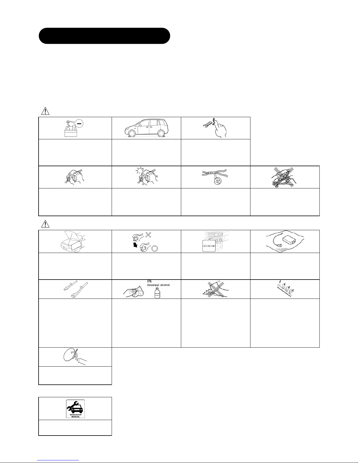
REQUIRED TOOLS
☆Screwdriver (Flathead) ☆Screwdriver (Phillips) ☆Socket wrench
☆Box-end wrench/Combination wrench ☆Torque wrench ☆Nipper
☆Pliers ☆Hole saw (20mm) ☆Drill (1.5mm,3mm)
☆Punch ☆Pincers ☆Remover tool
☆Flathead screwdriver wrapped with protective tape ☆Fastener remover wrapped with protective tape ☆Flat, round file
☆Round file ☆Deburring Tool ☆Masking tape
☆Soft clean cloth ☆Electrical vinyl tape ☆Mat
☆IPA (Isopropyl alcohol)
WARNING
If the negative battery is
connected while performing the
work, it may cause electrocution
or other personal injuries.
Disconnect the negative cable
before /installation.
Before performing any work,
park the vehicle on level ground,
apply the parking brake
securely, and then block the
wheels.
Be careful when handling drills
and other sharp objects.
If not handled properly, it could
result in serious injury.
When connecting/disconnecting
connectors, grasp the connectors,
not the wires. Otherwise, a fire or
other accident could occur due to
a short circuit or poor contact.
Make sure the connector is
securely pressed in until a click
sound is heard.
Otherwise, a fire or other
accident may occur due to an
open circuit or poor contact.
Secure the wiring harness with
the tape (part included) so that
they are not left dangling.
Otherwise, a fire or other
accident may occur due to a
short circuit.
Do not pull a wiring harness with
excessive force. Doing so can
cause breakage which could
result in a short circuit or a fire.
CAUTION
Be sure to cover the vehicle body
with protectors or mats to prevent
stains, scratches and damage
when removing/installing the
vehicle parts.
Using improper tools may
damage parts. Use the correct
tool for the job.
When the negative battery cable
is removed, the initial value or
memory for the power windows,
clock, i-stop, steering angle
sensor reference point will be
cleared. Perform re-initialization.
Put the removed parts and the
kit accessory parts on a
protective sheet to prevent
scratches.
Wrap protective tape around
screwdrivers and fastener
remover tools to prevent
scratching the vehicle.
If there is dust, dirt or grease on
the adhesion surface, the
adhesive strength of the
double-sided adhesive tape will
be weakened. Wash and
degrease the surface of the
adhesion area before applying
the double-sided adhesive tape.
Be sure to wash interior and
exterior parts using IPA
(
isopropyl alcohol).
If tape or a mount base is
removed and then re-adhered,
the adhesive strength will be
weakened. Before adhering,
accurately determine the
adhesion position.
To assure sufficient
adhesiveness of the
double-sided adhesive tape,
press the adhesive surface of
the tape to the adhesion surface
evenly.
In particular, press sufficiently at
the ends of the double-sided
adhesive tape where the
adhesion surface is curved.
Make sure to remove burrs from
the surface so that the bumper
surface is smooth.
Advice
Refer to the Workshop Manual
for removal and installation of
vehicle parts.
3. BEFORE INSTALLATION
Page 5
5
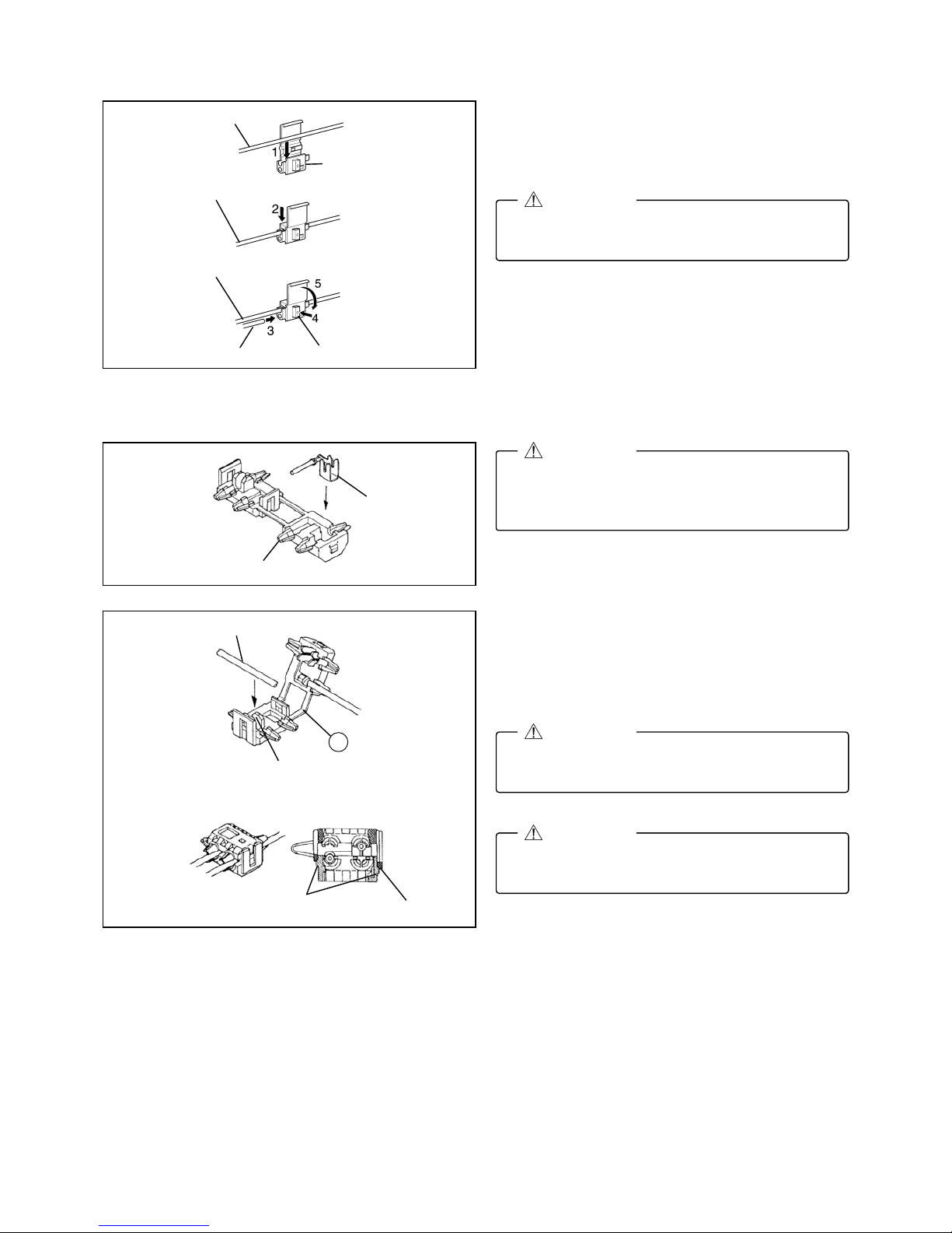
■ Branch connection procedure using electro tap
1. Insert the harness and vehicle wiring harness into
the electro tap.
2. Fold the electro tap as shown in the figure and lock
it.
3. Insert the harness to the end of the electro tap.
4. Firmly press the electro tap terminal using pliers.
5. Fold the electro tap in the direction of the arrow
shown in the figure and lock it.
6. Soundproof using urethane tape.
■ Branch connection procedure using electro-tap (Optional ON-OFF switch installed)
1. Put the harness to be branch-connected into the
guide groove.
2. Fold back the electro-tap from the A part as shown
in the figure.
3. Lock the electro-tap temporarily.
4. Firmly press the electro tap terminal using pliers.
Firmly engage the lock part until a click sound
is heard.
CAUTION
The temporary lock is provided on only one
side. Stop short of lockin
g
the final locks.
CAUTION
Pinch the electro-tap until a clicking sound is
heard from the final locks on the both sides.
CAUTION
Electro tap
Harness
Firmly press
using pliers
Vehicle wiring harness
Lock
Lock
Vehicle wiring harness
Terminal
Vehicle wiring harness
The terminal is embedded in the insulator. If it
is not, insert the terminal as shown in the figure
and press it in until it is securely fixed.
CAUTION
Terminal
Insulator
Guide groove
Harness
A
Temporary lock
Final lock
Page 6
6
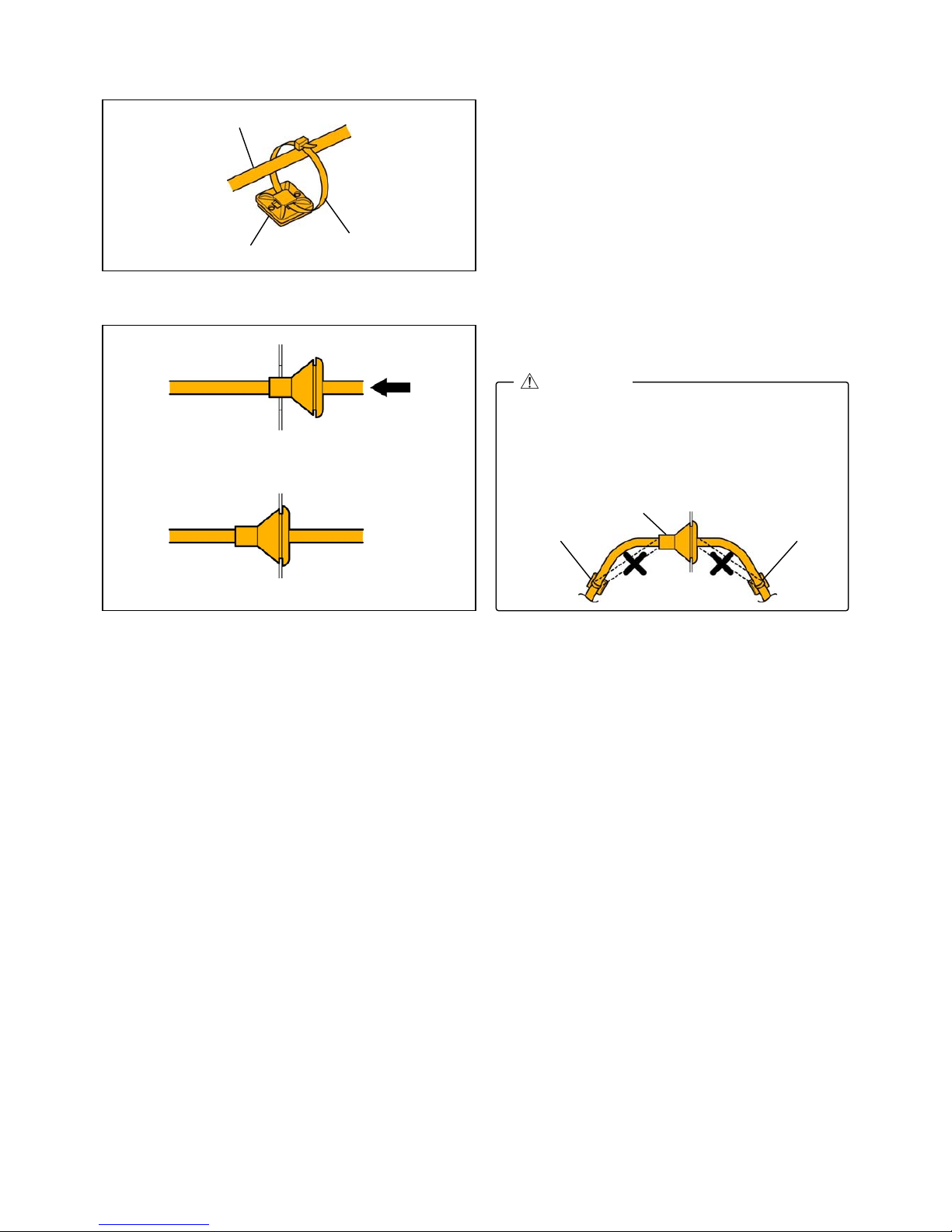
■ Securing harness
1. When the wiring harness is secured using a mount
base, passing a tie wrap through the mount base
and temporarily tightening the wiring harness as
shown in the figure will make the operation easier.
■ Securing grommet
1. When inserting the grommet, firmly press in the
entire circumference by hand.
Completely encapsulate with no eversion on
the grommet. Otherwise, water may penetrate
the cabin causing rust or a malfunction.
When securing the tie wrap, be careful not to
deform the grommet or separate it at the ends.
Grommet
Tie wrap Tie wrap
CAUTION
Tie wrap
Mount base
Harness
Press in
Vehicle interior Vehicle exterior
Installed condition
Vehicle interior Vehicle exterior
Page 7
7
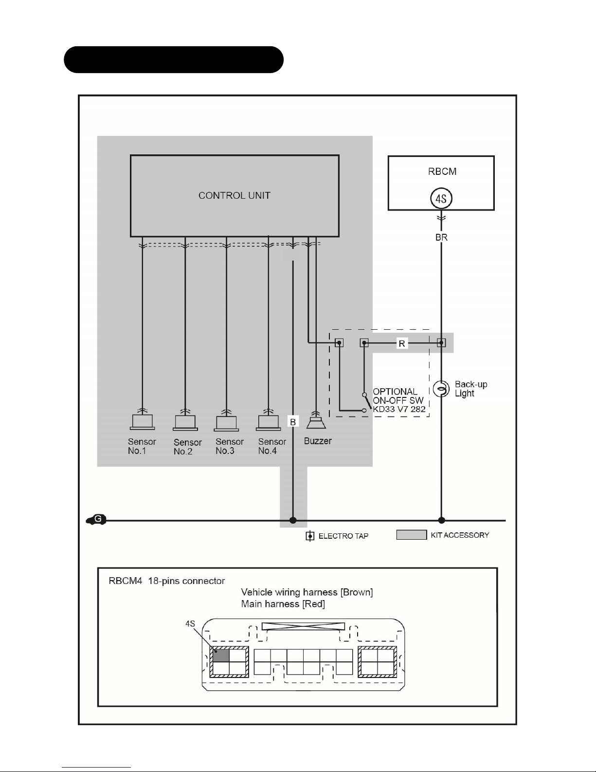
4.CONNECTION DIAGRAM
Figure shows connector viewed from harness side.
Wire color indicated in figure is wiring harness color for
parking sensor kit.
GR
Page 8

8
Negative battery cable disconnection
1. Set the selector lever to P range.
(AT vehicles only)
2. Disconnect the negative battery cable and wrap
tape around it to insulate.
Tightening torque : 4.0-6.0 N・m
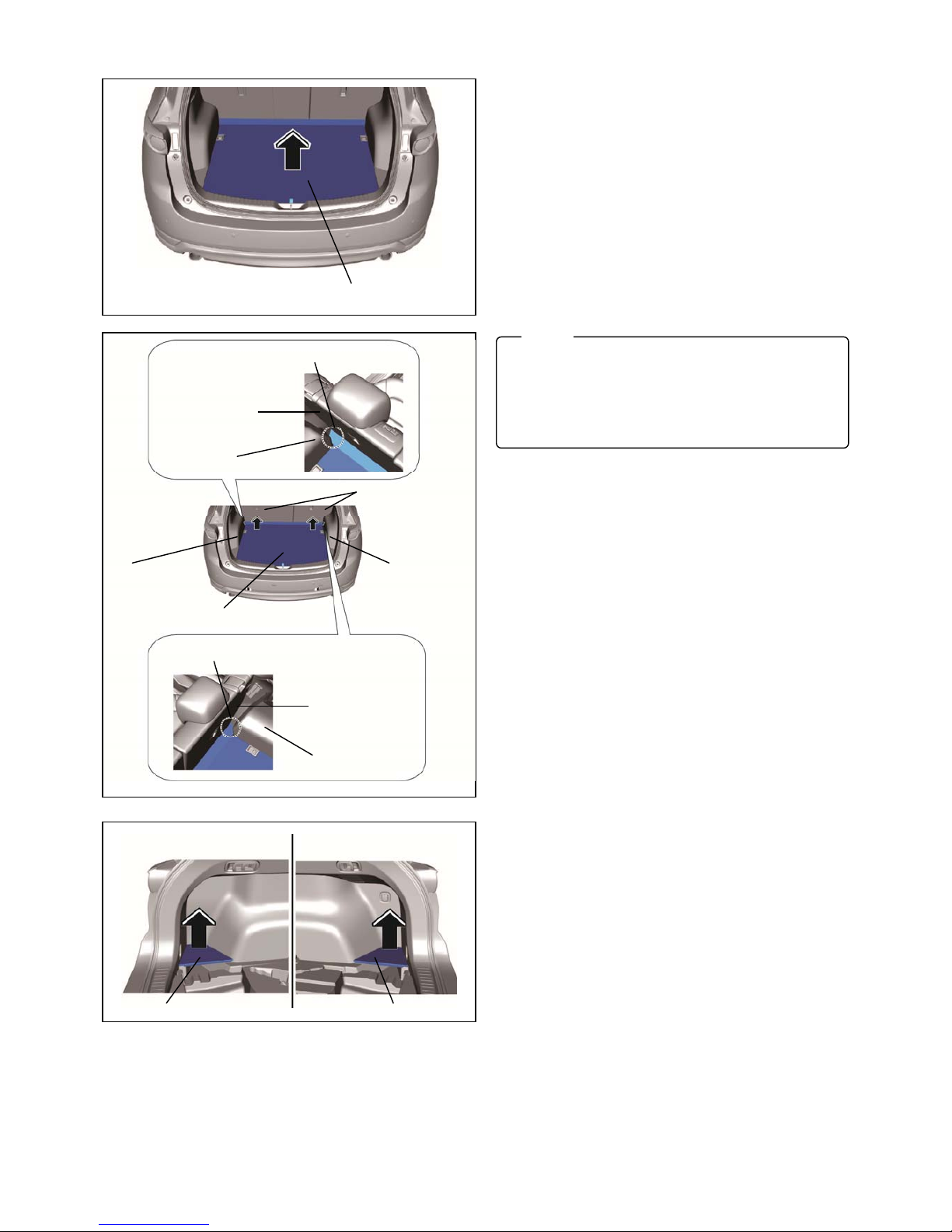
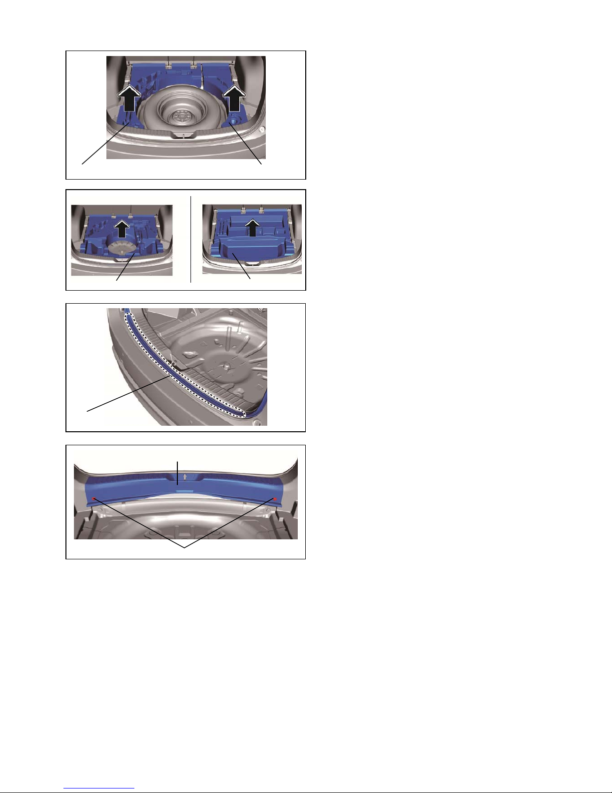
Tonneau cover removal
1. Hold the shaded areas shown in the figure and move
the tonneau cover in the direction of the arrow.
2. Remove the tonneau cover in the direction of the
arrow shown in the figure.
5. VEHICLE PART REMOVAL
Be careful not to damage or lose any parts removed from the vehicle since they will be reused.
CAUTION
When removing/installing the parts, park the
vehicle on level ground and apply the side
brake securely. Be sure to turn the ignition
switch off, otherwise the vehicle can move,
causing personal injury or vehicle damage.
WARNING
If the negative battery cable is connected while
performing the work, it may cause electrocution
or other personal injuries. Disconnect the
negative battery cable before
removal/installation.
WARNING
Negative battery cable
Vehicle front
Tonneau cover
Tonneau cover
Page 9
9
Trunk board removal
1. Remove the center trunk board.
2. Remove the trunk board RH and trunk board LH.
Center trunk board
Move the center trunk board in the direction of
the arrows shown in the figure, and remove the
ends of the center trunk board from the gap
between the trunk side trim and the rear seat
back.
Note
Trunk board RHTrunk board LH
End of center trunk board
End of center trunk board
Rear seat back
Trunk side trim
Rear seat back
Trunk side trim
Rear seat back
Trunk side trim Trunk side trim
Center trunk board
Page 10
10
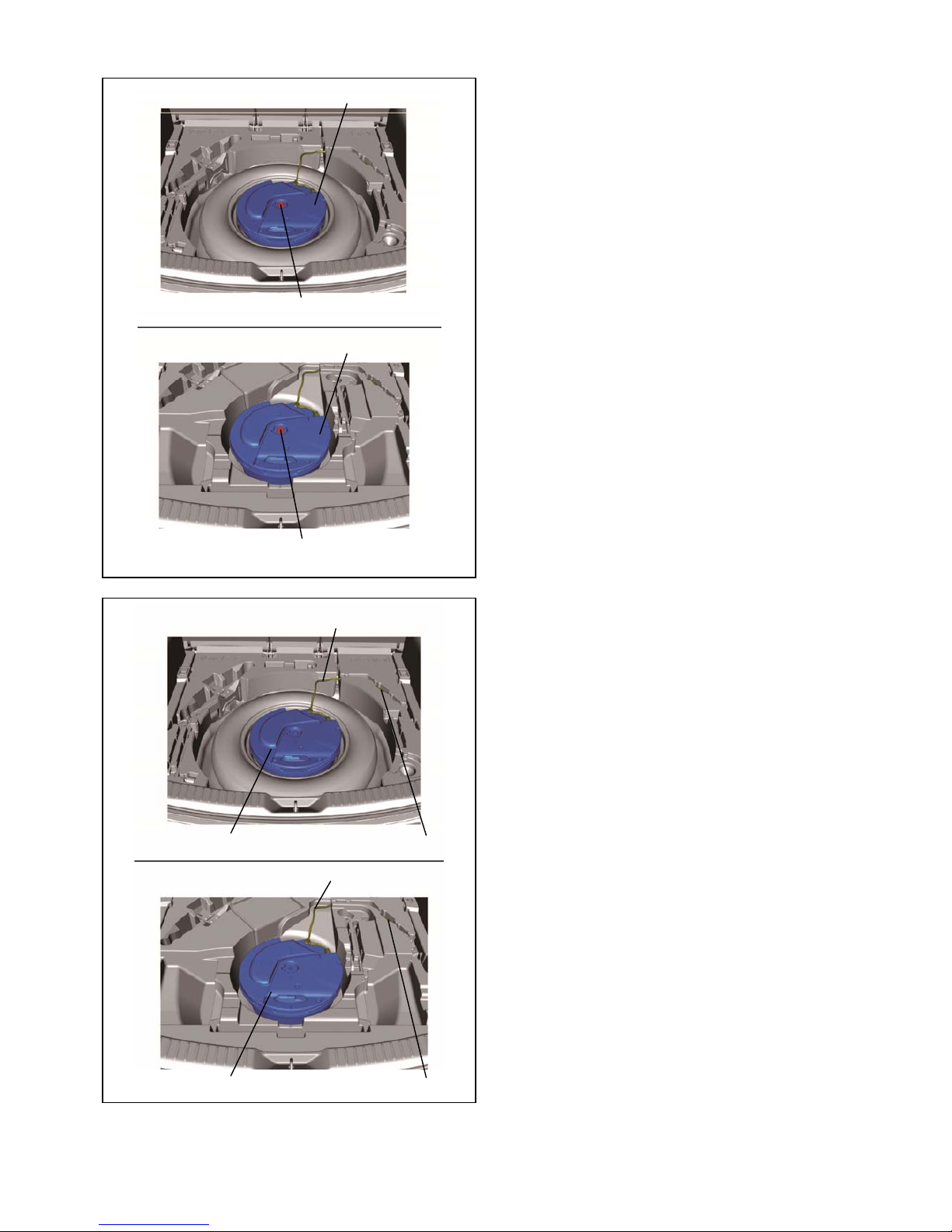
Bass-box removal
1. Remove the bolt.
2. Disconnect the connector.
3. Remove the bass box and short cord as a single
unit.
With spare tire
Short cord
Without spare
ConnectorBass box
ConnectorBass box
Short cord
Bolt : 4.0—8.0 N·m
{41—81 kgf·cm, 36—70 in·lbf}
Bolt : 4.0—8.0 N·m
{41—81 kgf·cm, 36—70 in·lbf}
With spare tire
Without spare tire
Bass box
Bass box
Page 11
11
Sub-trunk removal
[With spare tire]
1. Remove sub-trunks No.1 and No.2 in the direction
of the arrows shown in the figure.
[Without spare tire]
2. Remove the sub-trunk in the direction of the arrow
shown in the figure.
Trunk end trim removal
1. Partially peel back the weatherstrip.
2. Remove the fasteners.
Sub-trunk No.1 Sub-trunk No.2
Weatherstrip
Fastener
Tr
u
nk end trim
Sub-trunk
Sub-trunk
Page 12
12
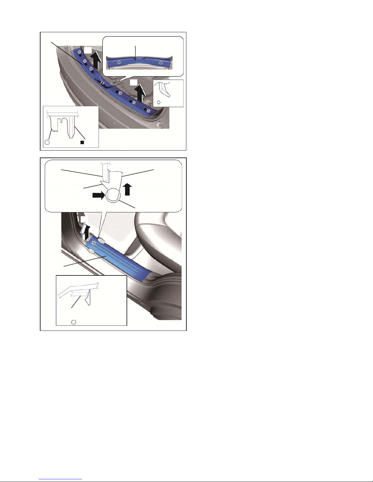
3. Move the trunk end trim in the order of arrows (1) and
(2) shown in the figure, remove it while detaching the
clips, pins, and the guides.
Rear scuff plate removal
1. Hold part A shown in the figure, open the rear scuff
plate in the direction of arrow (1), move it in the
direction of arrow (2), and detach tab A of the rear
scuff plate from the B-pillar lower trim.
2. Hold the shaded areas shown in the figure, move
the rear scuff plate in the direction of arrow (3),
and detach tab B of the rear scuff plate from the
B-pillar lower trim.
B-pillar lower trim
B-pillar lower trim
Rear scuff plate
Rear scuff plate
Tab A
Part A
(2)
(3)
(1)
: Tab B
Trunk end trim
Trunk end trim
: Guide
: Clip : Pin
(1)
(2)
Page 13

13
3. Hold the shaded areas shown in the figure, move
the rear scuff plate in the direction of arrow (1),
detach the clip from the inner panel, and pull out
the pin.
4. Hold the shaded areas shown in the figure, move
the rear scuff plate in the direction of arrow (3),
and remove it while detaching tab B of the rear
scuff plate from the trunk side trim.
5. Hold part A shown in the figure, open the rear scuff
plate in the direction of arrow (1), move it in the
direction of arrow (2), and detach tab A of the rear
scuff plate from the trunk side trim.
6. Hold the shaded areas shown in the figure, move
the rear scuff plate in the direction of arrow (3),
and remove it while detaching tab B of the rear
scuff plate from the trunk side trim.
(1)
(2)
Rear scuff plate
Inner panel
: Clip
: Pin
Rear scuff plate
(2)
Tab A
Part A
: Tab B
Trunk side trim
(1)
(3)
Trunk side trim
Rear scuff plate
Page 14

14
Trunk side trim removal
1. Insert a tape-wrapped flathead screwdriver into the
position shown in the figure, move it in the direction
of arrow (1), and while detaching the hooks of the
remote handle lever, open the cover in the direction
of arrow (2).
2. Remove the screw.
3. Remove the screw.
4. Remove the fastener.
Tape-wrapped flathead screwdriver
Hook
Hook
Remote handle leve
r
Cover
Cover
Hook
(2)
Hook
Remote handle leve
r
(1)
Remote handle lever
Scre
w
Scre
w
Trunk side trim
Trunk side trim
Fastener
Page 15

15
5. Remove the bolts.
6. Remove the cargo net hooks.
7. Partially peel back the weatherstrips.
8. Remove the rear seat cushion.
9. Fold the rear seat back.
10. Insert a tape-wrapped flathead screwdriver into
the position shown in the figure, move it in the
direction of the arrows, and remove the clips.
Tape-wrapped flathead screwdrive
r
: Clip
Trunk side trim
Bolt : 9—12 N·m {92—122 kgf·m, 80—106 ft·lbf}
Cargo net hook
Trunk side trim
Bolt
Cargo net hook
Bolt
Weatherstrip Weatherstri
p
Page 16

16
11. Move the trunk side trim in the order of arrows (1),
(2), (3), and (4) shown in the figure, and remove
the clips and hooks.
12. Move the trunk side trim in the order of arrows (1),
(2), (3), and (4) shown in the figure, and remove
the clips, hooks, and the clip of the remote handle
lever.
13. Insert a hand into the back side of the trunk side
trim, press the tabs of the remote handle lever in
the direction of arrows (1) shown in the figure,
and remove the remote handle lever in the
direction of arrow (2).
Tab
Trunk side trim
Remote handle lever
Trunk side trim
(1)
(1)
(2)
Tab
Tab
Remote handle lever
: Clip of remote
: Clip
: Hook
(1)
(2)
(3)
(4)
Trunk side trim
Right side only
Trunk side trim
: Cli
p
: Hook
(1)
(2)
(3)
(4)
Left side only
Page 17

17
14. Set the remote handle lever aside.
15. Move the position of the rear seat back in the
direction of arrows (1) and (2) shown in the figure,
while adjusting it at a position where the trunk
side trim can be removed, move the trunk side
trim in the direction of arrow (3) shown in the
figure, and remove it in the direction of arrow (4).
16. Disconnect the rear accessory socket connector.
Remote handle lever
Trunk side trim
Rear seat back
(1)
(2)
(3)
(4)
Rear accessory
socket connector
Trunk side trim
Rear accessory socket
Right side only
Page 18

18
Rear combination light removal
1. Insert the remover tool into the service hole at the
position shown in the figure.
2. Move the remover tool in the direction of arrow (1)
shown in the figure and pull out the service hole
cover tab from the rear combination light.
3. Remove the service hole cover.
4. Remove the screws.
Rear combination light
Vehicle frontVehicle front
Rear combination light
Tab
Service hole cove
r
Remover tool
(1)
Rear combination light
Screw
Service hole cover
Rear combination light
Service hole
When removing the rear combination light from
the body, it could interfere with the body and
cause scratching or damage to the body. When
removing the rear combination light from the
body, apply protective tape to the body.
CAUTION
Fogging or condensation on the inside of the
rear combination lights may occur due to a
natural phenomenon occurring as a result of a
temperature difference between the interior and
exterior of the combination lights. However, it
has no effect on the light performance because
the temperature inside the rear combination
lights rises after illuminating a rear turn light or
a period of time has elapsed.
Note
Page 19

19
5. To prevent scratches or damage, affix protective
tape to the position shown in the figure.
6. Pull the rear combination light in the direction of
arrow (1) shown in the figure and pull out the rear
combination light from the body.
7. Remove the clip from the rear combination light.
8. Turn the socket counterclockwise and remove it in
the direction of arrow (1) shown in the figure.
Protective tape Rear combination light
Socket
Rear combination light
Clip
Rear combination light
Clip
(1)
Rear combination light
View from A
Stud bolt
Hook
(1)
A
Page 20

20
9. Turn the grommet counterclockwise and remove it
in the direction of arrow (1) shown in the figure.
10. Disconnect the connector and remove the rear
combination light from the body.
11. Remove the grommet and from the body.
12. Remove the fasteners.
Screw installation note
1. Install the screws in the order of (1) and (2).
Grommet
Fastene
r
Rear combination light
Screw (1)
Screw (2)
Rear combination light short cord
Connector
Rear combination light
Grommet
(1)
When removing the rear combination light from
the body, the rear combination light may fall off
and be damaged. Remove the rear combination
light from the body while holding the rear
combination light on the lens side by hand.
CAUTION
Page 21

21
Rear splash shield removal
1. Remove the fastener.
2. Remove the fastener.
3. Pull the rear over fender in the direction of the arrow
shown in the figure and disengage the clips shown in
the figure.
Rear over fender
Fastener
Rear over fender
Fastene
r
Rear over fender
Cli
p
Page 22

22
4. Remove the fasteners.
5. Remove the screws.
6. Detach the tabs from the rear bumper and remove
the rear splash shield.
Rear splash shield
Fastene
r
Screw
Fastener
Vehicle front
Scre
w
Tab
Rear s
p
lash shield
Page 23

23
Rear bumper removal
1. Affix the protective tape to the position shown in the
figure to prevent scratches and damage.
2. Remove the cap.
3. Remove the screws A and B.
4. Remove the screws.
Protective tape
Ca
p
Cap
Screw A
Scre
w
B
ScrewA
ScrewB
Screw B : 6.9—9.8 N·m {71—99 kgf·cm, 62—86 in·lbf}
Screw Screw
Page 24

24
5. Remove the fasteners.
6. Press the tab of rear under cover and remove it.
7. Remove the fasteners.
8. Detach the rear bumper from the rear bumper slider
while holding the rear end of the rear bumper, moving
it in the direction of the arrows shown in the figure,
and detaching the hooks.
9. Move the rear bumper in the direction of the arrow
shown in the figure and detach it from rear bumper
bracket.
Fastener Rear bumper
Hook Hook
Rear bumper Rear bumper bracket
Rear under cover
Tab
Fastener
With rear under cover
Page 25

25
10. Disconnect the connectors.
11. Detach the wiring harness clip.
12. Remove the rear bumper.
[With blind spot monitoring system]
13. If the rear bumper is replaced, perform the blind spot
monitoring (BSM) radar test.
If the rear bumper installation position is changed
or individual differences (coating film/thickness)
occur, the blind spot monitoring control module
radar angle will deviate which could result in the
module not detecting a vehicle approaching from
the rear correctly. If the rear bumper is replaced,
perform the blind spot monitoring (BSM) radar
test.
CAUTION
Rear fender panel
Protective tape
Rear over fende
r
After removing rear bumper, it may hit the rear
over fender and cause a damage and/or injury.
Perform the following procedure to prevent the
rear over fender from being damaged.
― Fix the rear over fender and rear fender
panel with protective tape.
CAUTION
Rear bumpe
r
Connector
Clip
With rear parking sensor
Page 26

26
1. Masking not required.
2. Coat the sensor surface with the body color paint.
3. Use two-component urethane paint. (Main
component: acrylicpolyol, curing agent: isocyanate)
Maximum paint thickness: primer 30 um, paint and
coating 95 um in total.
4. When painting, use a spray gun to apply the paint
evenly.
Paint infiltration into connector must be avoided;
pin contact must be guaranteed after painting.
Maximum paint curing: 90 C for 1 hour.
5. After baking, do not touch the painted product until
it has cooled down completely.
Hot storage temperature: 85 C.
6. When the painting is dried, remove the sensors and
the bezels from plastic base.
6. PAINT SENSOR
Paint characteristics vary according to paint
type. Check manufacturer specifications
before painting.
CAUTION
Do not use lacquer paints because their
weatherproofing and adhesion characteristics
are poor.
CAUTION
Be careful not to peel off the paint when
removing the sensors and the bezels from
plastic base.
CAUTION
SURFACE TREA TMENTT
a: Paint same as body color
b: Masking not required
Page 27

27
■ Cutting the cushioning tape
7. Cut the cushioning tape into thirds as shown in the
left figure.
■ Sensor installation
1. Tap the punch into the center of the scribed cross-hair lines for sensor installation on the back side of the
bumper.
7. PREPARATION FOR INSTALLATION
Rear sensor
scribed cross-hair lines
Rear bumper back side
Installation view
Note
20mm
Rear bumper surface
Rear sensor
scribed cross-hair lines
Back sensor
scribed cross-hair lines
Cushioning tape
1/3
1/3
1/3
1/3
1/3
1/3
Page 28

28
2. Wrap the drill bit with duct tape as shown in the
figure.
3. Set the drill rotation to low speed.
4. With the drill bit pointed perpendicular to the
bumper, drill 3mm holes in the marked positions.
3mm hole
5. Drill 20mm holes in the center of each sensor hole
using a hole saw.
6. Using a utility knife, cut a notch into the upper part
of each sensor hole at the dimensions shown in the
figure on the left.
Always use a drill with a rotation speed
adjustment, otherwise the rear bumper may
deform.
Be careful when handling drills and other sharp
objects.
To prevent scratching and over-drilling,
always wrap the drill bit with duct tape.
CAUTION
Be careful when handling drills and other sharp
objects.
If not handled properly, it could result in serious
injury.
WARNING
Duct tape
10mm
Drill 3mm
Over-drilling prevention
Drill
Drill bit (shoulder)
(Drill at low speed)
Sensor hole
Rear bumper back side
Drill (3mm)
Center of the sensor hole
Hole sa
w
: 20mm
1 mm
1 mm
Page 29

29
7. Remove the bezel from the sensor and install it to the surface of the rear bumper with the bezel dot mark on the
top.
8. First install the spacer, then sensor with rubber to the back side of the rear bumper.
The shapes of the washers differ, therefore verify the shape before installing them.
Insert the sensor projection into the washer recess.
After installing, make sure the rear sensor and back sensor are securely pressed into the rear bumper.
CAUTION
Rear bumper back side
Rubber
Rear sensor
Sensor
spacer
Rear sensor
Back sensor
Rear bumper
back side
Rear bumper
back side
Rear bumper
back side
Rubber
Rubber
Rear bumper surface
Dot mark
Sensor
spacer
Sensor
spacer
(1)
(1)
(1)
(2)
(2)
(2)
(3)
(3) (3)
Page 30

30
■Control unit installation
1. Affix double-sided adhesive tape to the control unit.
2. Peel off the double-sided adhesive tape backing and adhere the
control unit to the body panel of the lower part inside of the trunk
side trim (driver’s side).
■Buzzer installation
1. Affix double-sided adhesive tape to the buzzer.
2. Peel off the double-sided adhesive tape backing and secure the
rear buzzer to the body panel of the upper inside part of the
trunk side trim (driver’s side).
Always remove dirt or oil because the adhesive strength of
the double-sided adhesive tape weakens.
CAUTION
Always remove dirt or oil because the adhesive strength of
the double-sided adhesive tape weakens.
CAUTION
Always remove dirt or oil because the adhesive strength of
the double-sided adhesive tape weakens.
CAUTION
Always remove dirt or oil because the adhesive strength of
the double-sided adhesive tape weakens.
CAUTION
Control unit
Double-sided
adhesive
Double-sided
adhesive
Buzzer
Control unit
Front
Buzzer
Front
Page 31

31
[ Main harness ]
8.INSTALLATION OF THE HARNESS
RBCM4 18-pin connector [Blue]
(View from harness side)
Cut the vehicle
wiring harness tube.
6cm (0.2 ft)
(1) Connect an electro-tap to the position shown in the figure.
(2) Wrap cushioning tape around the electro-tap.
RBCM
Cushioning tape
(1) Connect the main harness to the control unit.
Vehicle wiring harness
(5) Secure the main harness to the
vehicle wiring harness using ▲ tie wraps.
(3) Install the main harness.
To ②
When affixing the main wiring harness to the vehicle
harness using a tie wrap, do not affix the harness
together with the fuel filler lid opener cable.
CAUTION
Electro tap
Vehicle front
(4) Tie redundant part
using
▲
tie wrap.
Vehicle front
Vehicle wiring harness [Brown]
Main harness [Red]
Control unit
(2) Connect the main harness to the buzzer.
Buzzer
Sensor
harness
To ⑤
Connect an electro-tap for the main harness to the indicated signal line securely. Misconnection may
cause a system or vehicle malfunction.
For branch connection procedure using electro tap, refer to [Branch connection procedure using electro tap]
on page 5.
CAUTION
▲ Tie wrap (4)
Page 32

32
[ Sensor harness (1) ]
Vehicle with BSM
※ Install the wiring harness to the cabin interior from the rear bumper side.
Vehicle front
(1) Remove the hole cover
▲ tie wrap (1)
◆ Crump tie wrap (1)
Sensor harness
Connector for left rear sensor
Connector for right back sensor
♦
Mount base (7)
▲ Tie wrap (8)
Vehicle front
Sensor harness
(2) Affix grommet
From ③
Connector for back sensor
For affixing the grommet, refer to the
[Affixing grommet] on page 6.
CAUTION
To ②
The removed hole cover
is not reused with this
accessory.
Note
Center mark (white tape)
Page 33

33
[ Sensor harness (1) ]
Vehicle without BSM
※ Install the wiring harness to the cabin interior from the rear bumper side.
Vehicle front
♦
Mount base (1)
▲ Tie wrap (2)
Connector for left rear sensor
Connector for right back sensor
♦
Mount base (8)
▲ Tie wrap (8)
Sensor harness
Connector for back sensor
To ②
Center mark (white tape)
(1) Remove the hole cover
Sensor harness
Vehicle front
(2) Affix grommet
From ③
The removed hole cover
is not reused with this
accessory.
Note
For affixing the grommet, refer to the
[Affixing grommet] on page 6.
CAUTION
Page 34

34
[ Sensor harness (2) ]
※ Install the wiring harness to the cabin interior from the rear bumper side.
Sensor harness
Vehicle front
From ②
(1) Insert sensor harness terminals to female contact housing.
(2) Connect the sensor harness connector to the control unit.
Control unit
Sensor harness
Female contact housing
(Blue)
(Black)
(Red)
Page 35

35
[ Sensor harness (3) ]
Control unit
Vehicle front
Vehicle wiring harness
(3) Secure the main harness and sensor harness to
the vehicle wiring harness using ▲ tie wraps.
(2) Secure the main harness to the
vehicle wiring harness using ▲ tie wraps.
(1) Install the main harness and sensor harness
(1) Install the ground wire.
Vehicle wiring harness
Vehicle front
To ⑤
From ④
Ground bolt tightening torque : 8.8-12.7 N・m
(2) Tie redundant part
using
▲
tie wrap.
(3) Tighten together
with guround bolt.
▲ Tie wrap (4)
▲ Tie wrap (2)
Page 36

36
■Optional ON-OFF switch installation
2. Mark the back side of the driver-side trunk side trim
in the position shown in the figure using a punch.
3. Wrap the drill bit with duct tape as shown in the
figure.
4. Set the drill rotation to low speed.
5. With the drill bit pointed perpendicular to the
trunk side trim, drill 1.5mm holes in the marked
positions.
1.5mm hole (2 locations)
9.
INSTALLATION OF OPTIONAL ON-OFF SWITCH FOR USE WHEN TOWING
This procedure is not necessary if the [optional on-off switch for use when towing] is not installed.
Go to 9. CAUTIONS WHEN RE-INSTALLING.
Note
Always use a drill with a rotation speed
adjustment, otherwise the rear trunk side trim
may deform.
Be careful when handling drills and other sharp
objects.
To prevent scratching and over-drilling,
always wrap the drill bit with duct tape.
CAUTION
Be careful when handling drills and other sharp
objects.
If not handled properly, it could result in serious
injury.
WARNING
Duct tape
10mm
Drill 1.5mm
Over-drilling prevention
Drill
Drill bit (shoulder)
(Drill at low speed)
Reference line
Back side of driver-side trunk side trim
Vehicle front
20mm
43mm
10mm
Punch
Center of the Optional
ON-OFF switch hole
Notch area
Trunk side trim
back side
Page 37

37
6. Drill a hole in the center of each Optional ON-OFF
switch hole using a hole saw 20mm.
7. Remove the paper backing from the back-up
sensor ON-OFF switch (label) and adhere the label
to the driver-side trunk side trim.
8. Install the Optional ON-OFF switch harness by
passing it through from the surface of the
driver-side trunk side trim.
9. Secure the switch harness to the underside of the
trunk side trim (driver's side) as shown in the figure
on the left using cushioning tapes.
Optional ON-OFF switch hole
Drill (1.5mm) Notch hole
Driver-side trunk side trim
Drill (1.5mm)
Center of the Optional ON-OFF switch hole
Hole saw 20mm
Optional ON-OFF switch harness
Convex part
Back-up sensor
ON-OFF switch (label)
Convex part
Optional ON-OFF
switch
Back-up sensor
ON-OFF switch (label)
Driver-side trunk side trim
Vehicle front
Driver-side trunk side trim
Cushioning tape
Vehicle front
Page 38

38
■ Harness installation
1. Cut the main harness (Red wire) at the position
shown in the
figure.
2. Strip the main harness insulation and wrap
electrical vinyl tape around the tip of the stripped
main harness for insulation.
3. Connect the wiring harness included in the optional
on/off switch kit to the main harness stripped in
Step 1. with electro taps. (No polarity)
4. Wrap the electro taps in the 2 locations and the
harness connector with cushioning tapes.
Electro taps
Vehicle front
Harness connector
Cushioning tape
Cushioning
tape
RBCM
Always insulate the main harness.
CAUTION
For branch connection procedure using electro
tap, refer to [Branch connection procedure using
electro tap (Optional ON-OFF switch installed)]
on
pag
e 5.
CAUTION
Main harness
Vehicle front
Cut
Strip insulation
Wrap with electrical vinyl tape
Main harness
RBCM
Page 39

39
1. Reinstall parts in the reverse order of the installation procedure in “VEHICLE PARTS REMOVAL”.
Connect the main wiring harness to the rear sensor.
Connect the optional on-off switch harness to the harness.
2. Refer to “Required servicing after disconnecting/connecting negative battery cable” in the vehicle workshop
manual or the owner’s manual to restore the vehicle functions.
3. Perform reinstallation and inspection of the vehicle parts.
10.CAUTIONS WHEN RE-INSTALLING
Harness connector
Optional ON-OFF switch harness connector
Back side of driver-side trunk side trim
Vehicle front
When re-assembling, make sure the optional ON-OFF switch
harness does not become caught.
When re-assembling, make sure the optional ON-OFF switch
harness does not interfere with the seat belt.
CAUTION
Page 40

40
■ Is available when the ignition is switched ON and shift lever is in the R position.
■ The sensor detects obstructions when the shift lever is in the R position.
・ Alarm (beeper) sound
■ The beeper operates (sounds) as follows while the system is operating.
* The closer the obstruction is approached the faster the continuous sound is emitted.
Malfunction symptom Inspection Action
Alarm sound (buzzer) does not activate even though
there is an obstruction around the sensor.
Is the ignition switched ON? Switch the ignition ON.
Is each part connected correctly?
(Each connector, reverse signal line,
ground terminal)
Connect each part correctly.
Is there a device generating ultrasonic
waves near the vehicle?
(Air compressor, high-pressure car
washer, impact wrench, or electric drill)
Take the device away from the
ultrasonic wave generation
source.
Is the shift lever in the R position? Shift the shift lever to the R
position.
Alarm sound (buzzer) activates even though there is
no obstruction around the sensor.
Is the ground detected?
* If beep sound stops after placing
cardboard on the ground, the ground
may be detected.
Install the sensor correctly.
11.OPERATION CONDITION
12.TROUBLESHOOT
◇ Rear sensor ◇Back sensor
Distance between the vehicle
and the obstruction
Beeper
sound*
Slow
intermittent
sound
Fast
intermittent
sound
Continuous
sound
Slow
intermittent
sound
Fast
intermittent
sound
Continuous
sound
Distance between the vehicle
and the obstruction
Beeper
sound*
Approx.130-100cm (4.3-3.3 ft)
Approx.100-50cm (3.3-1.6 ft)
Within approx.40cm (1.3 ft)
Approx.60-50cm (2.0-1.6 ft)
Approx.50-40cm (1.6-1.3 ft)
Within approx.40cm (1.3 ft)
06DE4313B
 Loading...