

Page 1
GENUINE SATELLITE RADIO KIT
INSTALLATION INSTRUCTIONS
Thank you for purchasing a genuine Mazda accessory.
Before removal and installation, be sure to thoroughly read these instructions.
Please read the contents of this booklet in order to properly install and use the satellite
radio kit. Your safety depends on it.
Keep these instructions with your vehicle records for future reference.
x There are several WARNING and CAUTION sections in this booklet concerning
safety when installing. Always read and follow them in order to prevent injuries,
accidents, and possible damage to the vehicle.
WARNING
WARNING: Indicates a situation in which serious injury or death could result if the
warning is ignored.
CAUTION: Indicates a situation in which bodily injury or damage to the vehicle
could result if the caution is ignored.
x If in any doubt, please ask your Mazda dealer to install the accessory in order to
prevent errors in installation.
x If you have any questions about the use of the accessory, ask your Mazda dealer for
proper advice before using it.
x Mazda and its suppliers are not responsible for injuries, accidents, and damage to
persons and property that arise from the failure of the dealer or installer to follow these
instructions.
x To ensure safety and reliability of the work, installation, removal and disposal work
done by an Authorized Mazda Dealership is recommended.
x Be careful not to lose removed parts, and be sure that they are kept free from
scratches, grease or other dirt.
PART NAME: SATELLITE RADIO KIT
PART NUMBER: 0000 81 K11 (harness Kit G-X)
VEHICLE: MAZDA RX-8
(Applicable to 2010 model year vehicles and after)
NOTE
To the dealer
x Please turn over these instructions to the customer after installation.
To the customer
x Keep these instructions after installation. The instructions may be necessary for
installing other optional parts or removal of this accessory.
x Should the vehicle or this accessory be resold, always leave these instructions
with it for the next owner.
1ED6P11A23900
Mazda RX-8㧙1
Page 2

INSTALLATION VIEW
A
A
1
ANTENNA CABLE
ntenna cable
HARNESS (G-X)
SIRIUS and iPod
ntenna
Tie redundant part (GND)
To AUX connector
To Audio unit
DLP unit
Tie redundant part
GND
iPod connection cable㩷
Electro tap䇼(+B and ACC)䇽
Harness (G-X)
iPod integration module
Harness (G-X)
SIRIUS only
Tie redundant part (GND)
To AUX connector
To Audio unit
Mazda RX-8㧙2
GND
Electro tap䇼(+B and ACC)䇽
Harness (G-X)
Tie redundant part
Page 3
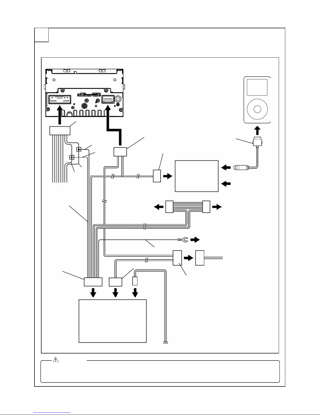
CONNECTION DIAGRAM
2
<Installation of SIRIUS and iPod integration module>
Audio unit
ACC
Harness (G-X)
Audio 24-pin
connector
+B
ACC
+B
16-pin connector (White)
16-pin connector (Black)
To Information display
(On market product)
iPod
iPod connection cable
iPod
integration module
NO CONNECT
To Vehicle wiring harness
To dashboard member
GND
To AUX or Bluetooth H/F
16-pin connector
(Gray)
8-pin connector
16-pin connector
DLP unit
(SIRIUS)
Antenna cable
CAUTION
x When connecting a connector, be sure to insert it straight along the guide.
The connector terminal may be bent if inserted at an angle.
Mazda RX-8㧙3
Page 4
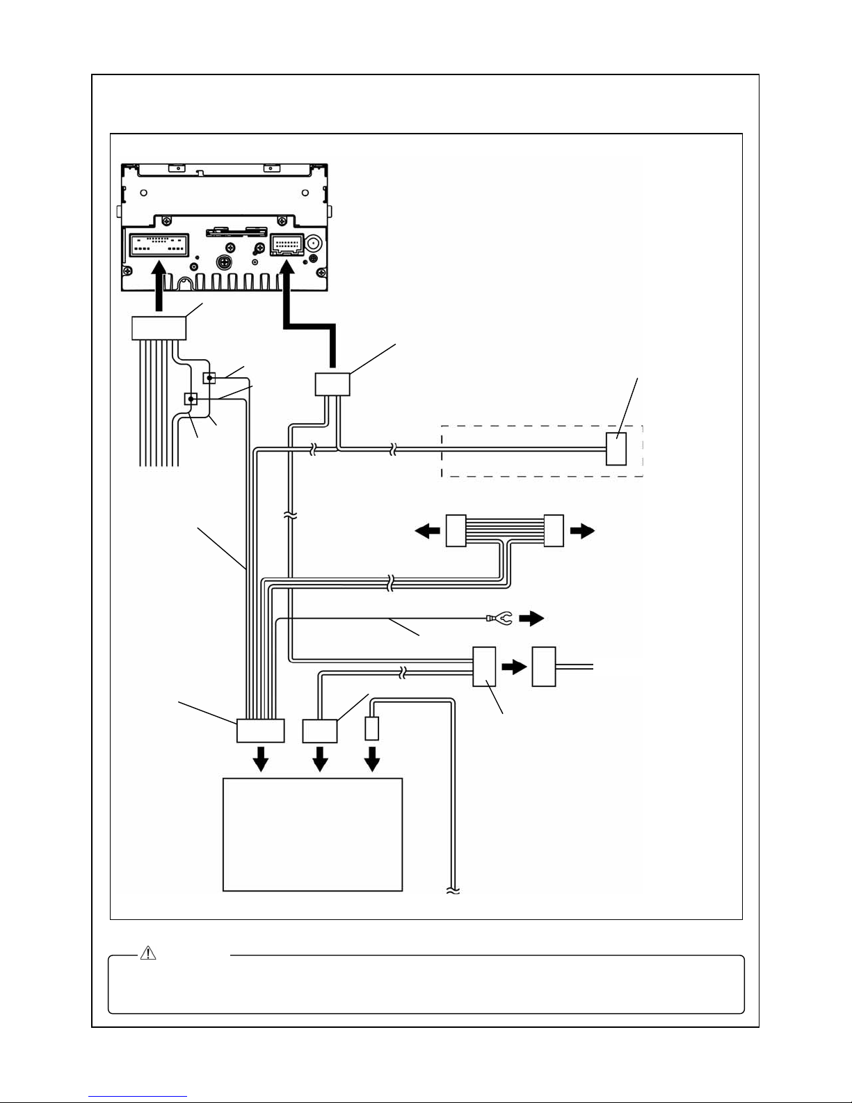
<Installation of SIRIUS only >
Audio unit
Audio 24-pin
connector
16-pin connector (White)
+B
ACC
Harness (G-X)
+B
ACC
Not used
(Wrap with pad protector)
To Information display
16-pin connector (Black)
To Vehicle wiring harness
GND
16-pin connector
(Gray)
8-pin connector
16-pin connector
DLP unit
(SIRIUS)
Antenna cable
CAUTION
x When connecting a connector, be sure to insert it straight along the guide.
The connector terminal may be bent if inserted at an angle.
To dashboard member
To AUX or Bluetooth H/F
Mazda RX-8㧙4
Page 5
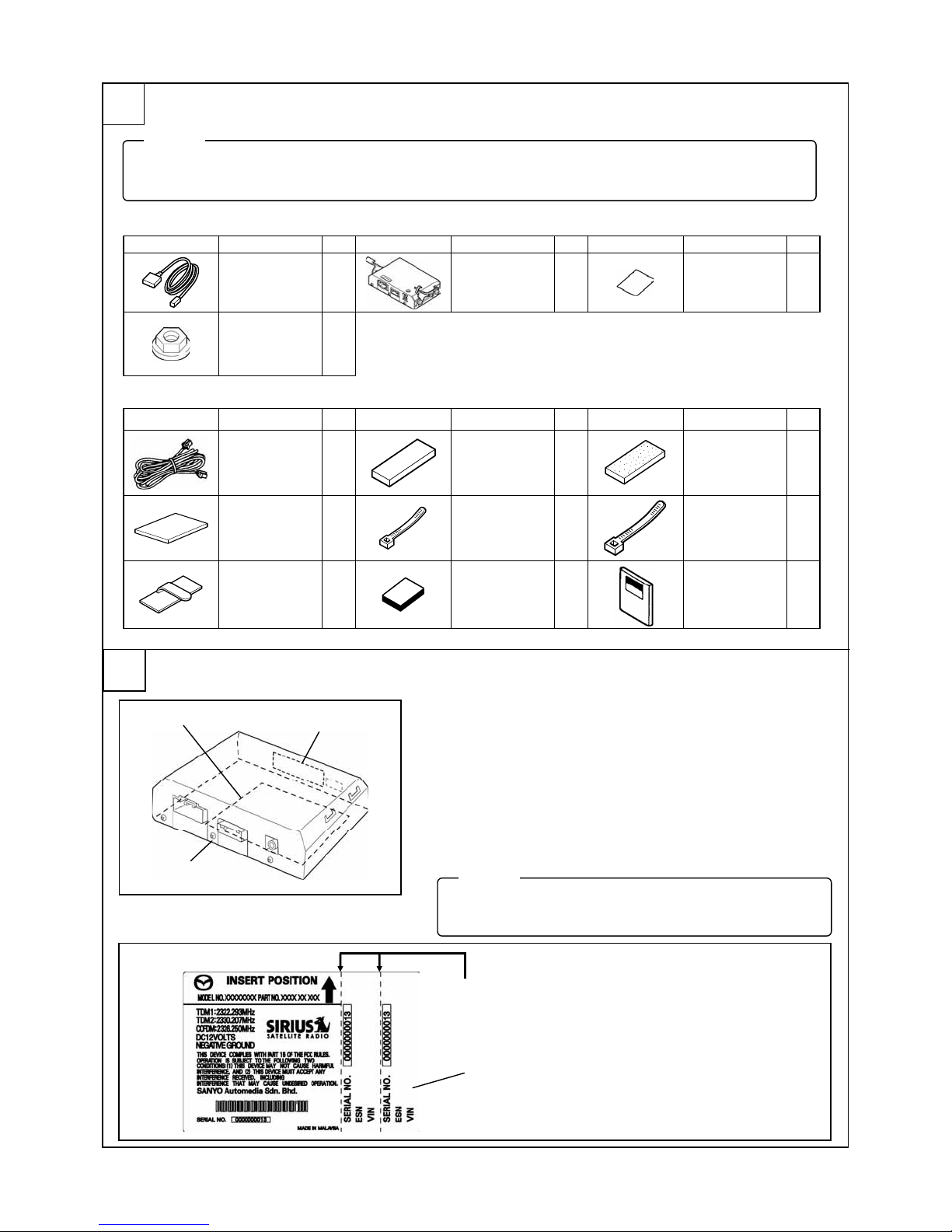
PARTS
3
NOTE
x Verify that the kit includes all the following parts and that they are free of dirt, scratches or damage.
x All hardware required to install is contained in the 0000 81 Z25 Satellite Radio Kit.
Main Kit (0000 81 Z40)
Part㩷 Part name㩷 Qty.㩷 Part㩷 Part name㩷 Qty. Part㩷 Part name㩷 Qty.
Antenna 1
Nut 2
Harness Kit G-X (0000 81 K11)
Part㩷 Part name㩷 Qty.㩷 Part㩷 Part name㩷 Qty. Part㩷 Part name㩷 Qty.
Harness (G-X) 1
Urethane 1
Clip 6
BEFORE INSTALLATION
4
Rating label
DLP unit
Sirius ID (ESN)
ԙ Ԙ
DLP unit 1
Double-sided
adhesive tape
Tie wrap
(Small)
Butyl tape 1
2
21
Alcohol wipe 1
Pad protector 19
Tie wrap
(Large)
Installation
instructions
Rating Label Removal
1. Tear off lower part of the rating label on the bottom of DLP
unit.
2. If there is nothing written in the Sirius ID (ESN) space of
the rating label, write down the 12-digit number printed in
the location shown in the figure.
3. Affix one rating label in the last page of the Owner’s
Manual.
NOTE
x The other rating label is for the dealer (port) records.
x Do not fail to submit the record.
Tear off
Ԙ Affix to the back of the Owner’s Manual.
ԙ Submit to the manager of installation department.
Rating label
19
1
Mazda RX-8㧙5
Page 6
REQUIRED TOOLS
Prepare the following tools or items before installation.
䃂Electrical vinyl tape 䃂Mat 䃂Scissors 䃂Scale ٨Phillips screwdriver ٨Torx wrench 䃂Wrench
䃂Socket driver (8 mm, 10 mm, 14 mm) 䃂ISP alcohol
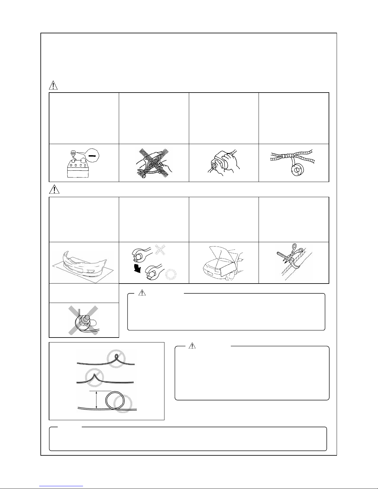
WARNING
When the negative battery
cable is connected during
operation, it may cause
electric shock or other
personal injuries.
Disconnect the negative
battery cable before
removal/installation.
When
connecting/disconnecting
connectors, grasp the
connectors, not the wires.
Otherwise a short, an
accident from poor contact
or fire may occur.
Do not pull the harness
with excessive force. Doing
so can cause a breakage
or a short-related accident,
as well as an electrical
short or fire.
Secure the harness with
the band (part included) so
it doesn’t dangle. If not, it
may cause a short,
accident, or fire.
CAUTION
Put the removed parts and
the parts in the kit on the
protective sheet to prevent
scratches.
Take care not to trap
antenna cable under
attachment nuts.
20 {0.78}
NOTE
x When the negative battery cable is removed, the clock, radio, trip meters and other memories will be
erased. Before performing work, record the content of the memory.
Using improper tools may
cause damage and or
broken parts. Use the
correct tool for the job.
WARNING
x When removing/installing the parts, park the vehicle on level ground
and apply the side brake securely. Be sure to turn the ignition switch
off, otherwise the vehicle can move, causing personal injury or
vehicle damage.
mm {in}
Be sure to cover the
vehicle body with
protectors or mats to
prevent stains, scratches
and damage when
removing/installing the
vehicle parts.
Excessive length of tie
wrap may interfere with
other parts and cause
damage.
Cut unnecessary part up to
about 5 mm {0.19 in} from
the fixed point.
CAUTION
x During the installation of the antenna cable make
sure the cable is not pinched, knotted “kinked” or
coiled too tightly. It is recommended that a coil of
less than 20 mm {0.78 in} be avoided if possible.
x If this wiring procedure is not followed, the
performance of the antenna will be affected and
could result in increased audio muting.
Mazda RX-8㧙6
Page 7
A
A
A
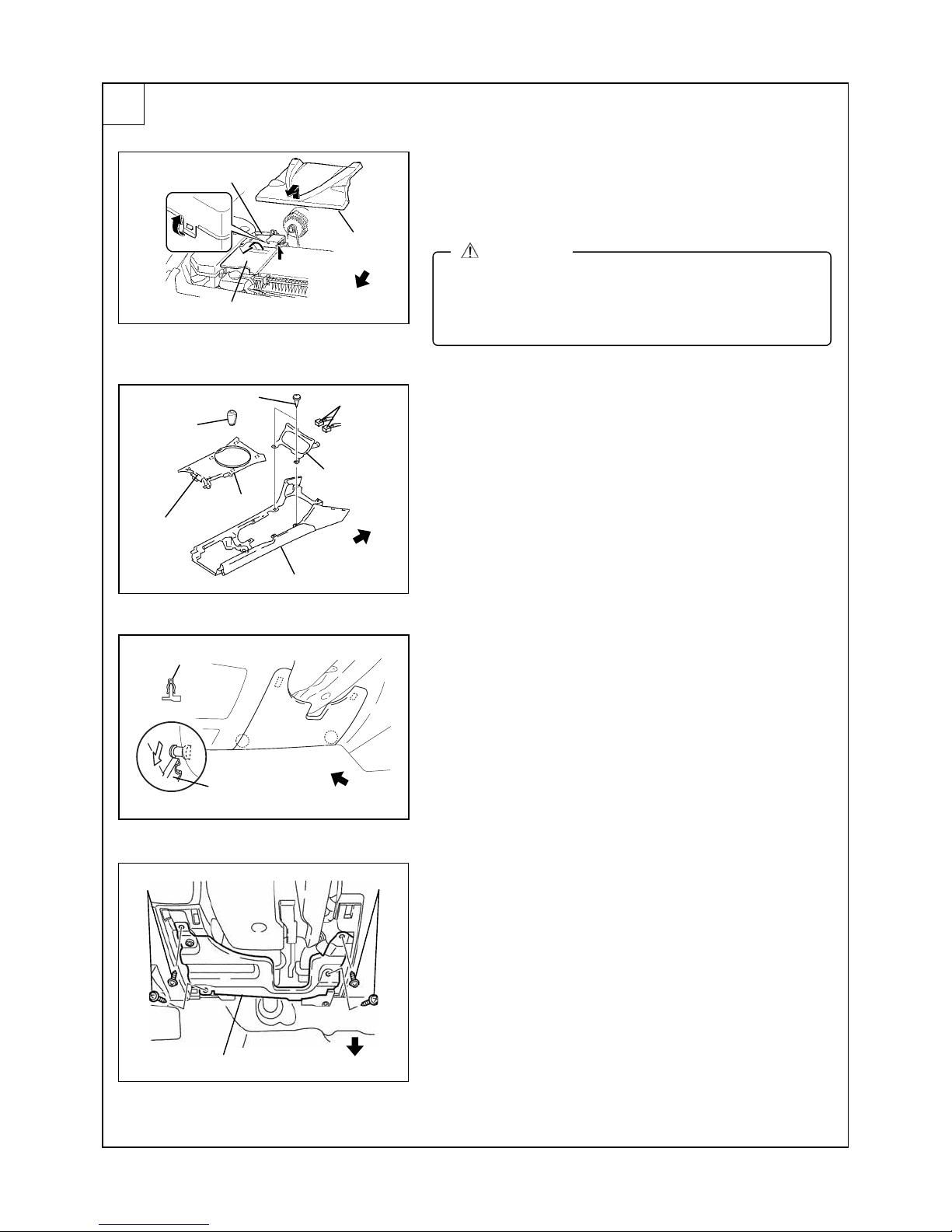
PART REMOVAL
5
Hose
Battery cover
Screws
Shift knob
Clips
Upper panel
Engine cover
Vehicle front
Connectors
Vehicle front
Front console
shtray
Battery cover removal
1. Remove the engine cover.
2. Remove the hose from the battery cover.
3. Remove the battery cover by lifting up from the rear.
WARNING
x A short circuit while performing work may cause
damage to parts, electric shock or other injury. Be
sure to disconnect the negative battery cable and do
not allow the terminal to contact any other parts.
Upper panel and ashtray removal
1. Remove the shift knob. (MT vehicles only)
2. Disengage the upper panel clips (6) using a tape-wrapped
flathead screwdriver, and remove the upper panel from
the front console.
3. Remove the ashtray screws (2).
4. Disconnect the connector and remove the assist tray from
the front console.
Screws
Clips A
Knee bolster
B
Hooks B
B
Vehicle front
Screws
Vehicle front
Lower panel removal
1. Pull the lower part of the lower panel forward to disengage
clips A (2).
2. While pushing the lower panel downward, disengage
hooks B (2) and remove the lower panel.
3. Remove the screws (4), then remove the knee bolster.
(If equipped)
Mazda RX-8㧙7
Page 8
Center panel unit
䌁
䌁
䌁
Screws
Vehicle front
Speaker㩷grille㩷
Clips A
Tabs B
<Speaker㩷grille removal note>㩷
Press
Audio side connectors
䌁
Bolt
Antenna feeder
䌁
Vehicle front
Air
Conditioner
side connector
Vehicle front
Speaker grille
Clips A
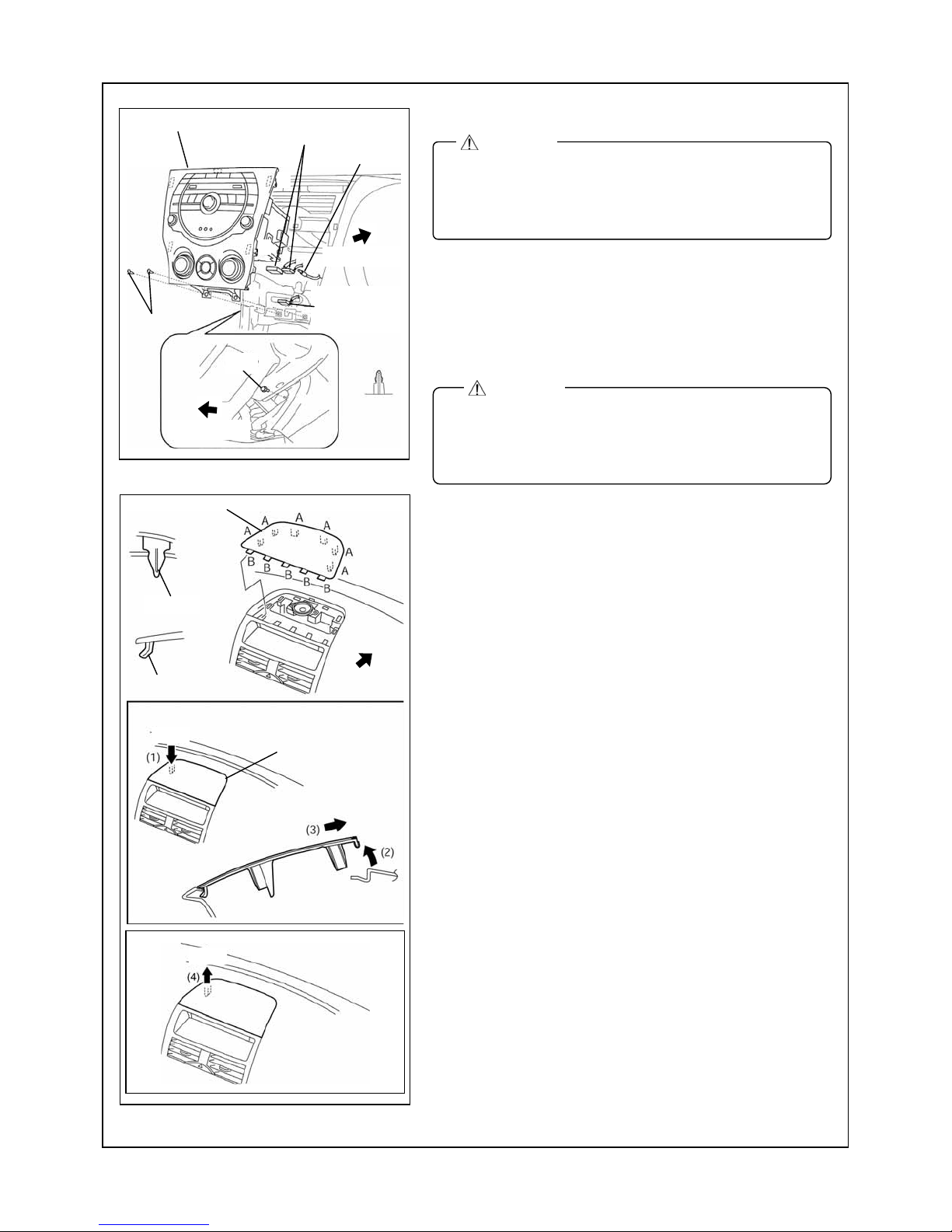
Center panel unit removal (Audio-integrated)
CAUTION
x Always wear gloves when working to protect the
special paint treatment of the center panel unit.
x If the painted surface becomes dirty, use a soft cloth
to wipe it clean.
1. Remove the bolt (1).
2. Remove the screws (2).
3. Pull the center panel unit outward, then remove clips A (5).
4. Remove the air conditioner side connector.
5. Disconnect the audio side connectors (2), the antenna
feeder (1 location), and then remove the center panel unit.
CAUTION
x Do not apply excessive force when pulling out the
center panel; otherwise it could cause an open circuit.
x When installing the center panel unit, make sure that
the harness and the antenna feeder are not caught.
Speaker
1. Press the area (1) in the direction of the arrow shown in
2. Raise the speaker grille in the direction of the arrow (2)
3. Pull up the speaker grille in the direction of the arrow (4)
4. Pull out the speaker grille from the fulcrum point of each
grille removal
the figure.
and pull it out in the direction of the arrow (3).
and disengage the speaker grille clips A (6).
tab B.
Pull
Mazda RX-8㧙8
Page 9
Vehicle front
Vehicle front
Stopper
Glove compartment
Clip A
Connector
A
Vehicle front
Tabs A㩷
Center panel㩷
Screws㩷
Information display㩷
Screws
Stay damper
Vehicle front
Stopper
Clip
Inner scuff plate
A
A
A
A
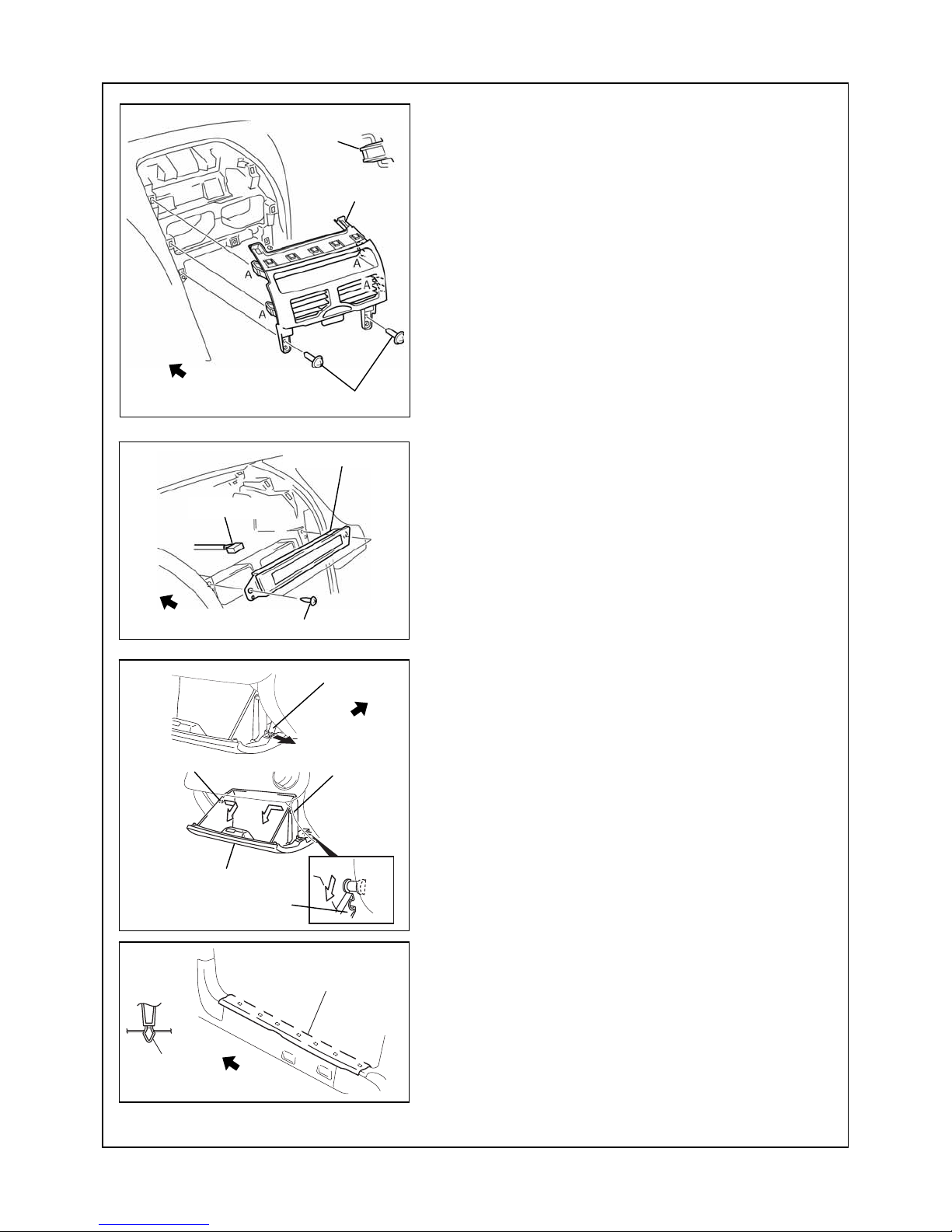
Center panel removal
1. Remove the center panel screws (2).
2. Pull the center panel outward and disengage tabs A (4).
3. Disconnect the hazard switch connector and remove
the center panel.
Information display removal
1. Remove the screws (2).
2. Pull the information display outward, disconnect the
connector and remove the information display.
Glove compartment removal
1. Pull the stay damper in the direction shown in the figure,
and detach the connecting part between the glove
compartment and stay damper.
2. Press the stoppers in and removal them.
3. Lower the glove compartment.
4. Detach the clips from the dashboard and remove the
glove compartment.
Inner scuff plate (passenger’s side) removal
1. Pull the inner scuff plate upward, detach clips A from the
body, and then remove the inner scuff plate.
A
A
Mazda RX-8㧙9
Page 10

A
A
A
A
A
A
A
A
D
Rear seat cushion
Vehicle front
Fasteners
Clip A
B
Front side trim
Rear seat back
A
C
B
C
B
Tire house trim
C
Vehicle front
C
B
Vehicle front
Trunk end trim
B
C
C
Locator pin B
Tab C
Bolt (12 mm)
17㧙20 N㨯m
{1.8㧙2.5 kgf㨯m,
13㧙18 ft㨯lbf}
Clip A
Locator pin B
Tab C
B
Front side trim (passenger’s side) removal
1. Partially peel back the seaming welt.
2. Pull the front side trim in the direction of the arrow and
detach clips A and locator pin B.
3. Detach the tab D, then remove the front side trim.
Rear seat (passenger’s side) removal
1.Lift the point A in the direction of the arrow, then remove
the rear seat cushion.
2. Remove the bolts, then remove the rear seat back.
Tire house trim (passenger’s side) removal
1. Partially peel back the seaming welt.
2. Pull the tire house trim outward and detach clips A and
locator pins B.
3. Detach tabs C and removal the tire house trim.
Trunk end trim removal
1. Remove the fasteners.
2. Pull the trunk end trim upward, then detach clips A, locator
pins B, and tabs C.
3. Remove the trunk end trim.
Fasteners
Clip A
Locator pin B
C
Mazda RX-8㧙10
Page 11

Fasteners
Trunk side trim
Nuts (8 mm)
3.9㧙5.9 N㨯m {40㧙60 kgf㨯cm, 35㧙52 in㨯lbf}
Connector
Vehicle front
Rear combination light
Vehicle front
Trunk side trim (passenger’s side) removal
1. Remove the fasteners, then remove the trunk side trim.
Rear combination light (driver’s side) removal
1. Disconnect the connector.
2. Remove the screw.
3. Remove the rear combination light.
Mazda RX-8㧙11
Page 12

INSTALLING DLP UNIT
r
w
r
w
6
Scre
Washe
Bracket
DLP unit
Bush
Washe
Pad protectors
DLP unit
Cut
Bush
Bracket
Scre
1. Remove the bushes (4 locations), brackets (2 locations),
washers (4 locations), and screws (4 locations) from the
DLP unit.
Note
x The brackets are not used with the installation of this
accessory.
2. Affix pad protectors to the DLP unit as shown in the
figure.
CAUTION
x To ensure proper affixing, be sure to degrease the
area where the pad protector is affixed.
3. Cut off the excess part of pad protectors.
DLP unit
Pad protector 1/2
Double-sided adhesive tapes
Pad protectors
DLP unit
4. Adhere double-sided adhesive tapes to the top of the pad
protectors.
5. Affix pad protector half to the DLP unit as shown in the
figure.
CAUTION
x To ensure proper affixing, be sure to degrease the
area where the pad protector is affixed.
Mazda RX-8㧙12
Page 13

{in}
A
Side body panel
Vehicle front
Pad protector
DLP unit
Tie wraps (large)
DLP unit
lign side of DLP unit with
line of side body panel
120 {4.72}
mm
Tie wraps (large)
6. Secure the tie wraps (large) to the DLP unit with a pad
protector as shown in the figure.
7. Install the DLP unit to the inside of the side body panel of
the trunk compartment using tie wraps (large).
(With the connector towards the front of the vehicle.)
CAUTION
x When securing the DLP unit, be sure to align the side
of the DLP unit with the line of the side body panel.
If it deviates rearward of the side body panel line,
the DLP unit will interfere with the trunk side trim and
cannot be installed.
x To ensure proper affixing, be sure to degrease the
area where the double-sided adhesive tape is affixed.
Mazda RX-8㧙13
Page 14

A
A
{
A
A
INSTALLING ANTENNA
7
Center
dhesion area
ntenna
Trunk lid
<Cross-sectional view>
Vehicle front
Trunk lid
Center
15㧙20
{0.54㧙0.78}
618
24.33}
Clip
Clips
(100 {3.93} interval)
Tie wraps (small)
Vehicle front
100 {3.93}
100 {3.93}
mm {in}
Vehicle front
mm {in}
Vehicle front
ntenna cable
mm {in}
ntenna cable
1. Clean the adhesion area on the trunk lid with isopropyl
alcohol (IPA).
2. Install the antenna in the position shown in the figure.
CAUTION
x To ensure proper affixing, be sure to degrease the
area where the double-sided adhesive tape is affixed.
3. Clean the adhesion area on the trunk lid with isopropyl
alcohol (IPA).
4. Attach the clips to the trunk lid.
5. Install the antenna cable to the clips.
6. Secure the antenna cable to the vehicle wiring harness with
tie wraps (small).
CAUTION
x It is critical that the antenna follows the route as
shown. Failure to follow this route will not provide the
slack required to open and close the trunk lid.
x Do not remove trunk seam from the flange. The
antenna cable must not interfere with the flange
seals.
Mazda RX-8㧙14
Page 15

{in}
Antenna cable
Seaming welt
10-15
{0.39-0.59}
Body crease
No interference of butyl tape with body
projection or within 10 mm of hole
mm
Antenna cable
Tie wraps (small)
Vehicle wiring harness
Tie wraps (small)
Vehicle front
Antenna cable
40 {1.57}
Pad protector halves should
be below the body crease.
Tie wraps (small)
Vehicle wiring harness
Tie wraps (small)
Do not put
pad protectors
within 35 {1.37}
of opening
Butyl tape
Pad protector 1/2
Vehicle front
Vehicle front
Antenna cable
7. Pull the seaming welt up slightly on the flange and route
the antenna cable under the outside lip.
8. Clean the adhesion area with isopropyl alcohol (IPA).
9. Secure the antenna cable in place with butyl tape and
10. Secure the antenna cable to the vehicle wiring harness
11. Secure the antenna cable to the vehicle wiring harness
12. Secure the antenna cable to the vehicle wiring harness
CAUTION
x Be careful not to tear the seaming welt when puling it out.
x Do not remove trunk seam from the flange. The antenna
cable must not interfere with the flange seals.
pad protector halves.
CAUTION
x To ensure proper affixing, be sure to degrease the area
where the pad protector is affixed.
x Do not wrap butyl tape around flange.
x Do not double-layer tape.
Butyl tape should hold the antenna cable to the sheet
metal as shown.
x Take care not to trap antenna cable under attachment
nuts.
with tie wraps (small).
CAUTION
x During the installation of the antenna cable make
sure the cable is not pinched, knotted “kinked” or
coiled too tightly. It is recommended that a coil of less
than 20 mm {0.78 in} be avoided if possible.
x If this wiring procedure is not followed, the
performance of the antenna will be affected and
could result in increased audio muting.
with tie wraps (small).
with tie wraps (small).
Mazda RX-8㧙15
Page 16

13. Secure the antenna cable to the vehicle wiring harness
with tie wraps (small).
14. Connect the antenna cable to the DLP unit.
15. Bundle the redundant part of the antenna cable into a loop
and affix it to the vehicle panel using pad protector halves.
CAUTION
x Be sure to bundle the harness into a loop.
x To ensure proper affixing, be sure to degrease the
area where the pad protector is affixed.
NOTE
x Bundle the antenna cable into a loop and attach it to
the sheet metal on the interior side of the trunk, and
secure with pad protector halves.
DLP unit
Vehicle front
Antenna cable
Tie wraps (small)
Pad protector 1/2
Vehicle wiring harness
INSTALLING iPod INTEGRATION MODULE
8
NOTE
x When installing Sirius only, begin with Step 1 on page 21.
iPod integration module
Pad protector
Pad protector㩷1/2 x 1
Pad protectors㩷1/3 x 3
Tie wrap (large)
iPod integration module
Pad protectors㩷1/3 x 3
Preparation for iPod integration module installation
1. Affix the tie wrap (large) to the iPod integration module
with a pad protector (1) as shown in the figure.
x To ensure proper affixing, be sure to degrease the
2. Affix the pad protectors to the iPod integration module as
x To ensure proper affixing, be sure to degrease the
CAUTION
area where the pad protector is affixed.
shown in the figure.
CAUTION
area where the pad protector is affixed.
Mazda RX-8㧙16
Page 17

iPod connection cable
iPod integration module
Pad protector
Harness (G-X)
3. Connect the harness (G-X) and iPod connection cable to
the iPod integration module.
4. Fold back the harness (G-X) and affix it to the iPod
integration module using a pad protector as shown in the
figure.
CAUTION
x To ensure proper affixing, be sure to degrease the
area where the pad protector is affixed.
Bracket
Bracket
Vehicle wiring harness clip
iPod integration module
Tie wrap (large)
Vehicle wiring harness
Vehicle front
Vehicle front
Vehicle front
5. Remove the vehicle wiring harness clip from the bracket.
6. Secure the tie wrap (large) installed on the iPod
integration module to the vehicle wiring harness on
the back of the dashboard.
Mazda RX-8㧙17
Page 18

INSTALLING THE HARNESS
9
Installation of SIRIUS and iPod integration module
Harness (G-X)
iPod integration module
iPod connection cable
Vehicle front
Dashboard
Vehicle front
mm {in}
Tie wrap (small)
100 {3.93}
Harness (G-X)
Information display 12-pin connector
㿈
Vehicle front
Pad protector
Vehicle wiring harness
1. Route the harness (G-X) to the back of the center panel
unit and to the back of the information display.
2. Affix the pad protector to the dashboard as shown in the
figure.
x To ensure proper affixing, be sure to degrease the
CAUTION
area where the pad protector is affixed.
3. Insert and connect the harness (G-X) to the Information
display 12-pin connector.
4. Secure the harness (G-X) to the vehicle wiring harness
with tie wrap (small).
Mazda RX-8㧙18
Page 19

Vehicle front
Vehicle front
Pad protector
Vehicle front
Harness (G-X)
To Audio unit
Harness (G-X)
Harness (G-X)
To Audio unit
Tie wrap (small)
To AUX connector
Pad protector 1/2
AUX, Bluetooth H/F
Pad protector
Harness (G-X)
(16-pin connector)
㿈
Vehicle bolt
GND
㿈
㿉
㿉
5. Affix a pad protector on the information display connector.
x To ensure proper affixing, be sure to degrease the
CAUTION
area where the pad protector is affixed.
6. Wrap a pad protecor around the rear side of the harness
(G-X) 16-pin connector.
7. Connect the harness (G-X) 16-pin connector to the AUX,
Bluetooth H/F connector.
8. Affix the pad protector half to the dashboard member as
shown in the figure.
x To ensure proper affixing, be sure to degrease the
CAUTION
area where the pad protector is affixed.
9. Insert the harness (G-X) GND wire between the
dashboard and the dashboard member and secure it
using the vehicle bolt.
x Make sure the ground eyelet contacts the steel
CAUTION
bracket.
10. Bundle the redundant part of harness (G-X) GND wire
and secure it to the harness (G-X) using a tie wrap
(small).
Mazda RX-8㧙19
Page 20

㩷
Vehicle front
Urethane
Vehicle wiring harness
[Audio 24 pin connector ]
(View from wire side of connector)
Terminal R: ACC
Kit wire: ACC
Pad protector
iPod
integration module
Tie redundant
part
Remove connector cover when connecting
iPod; fit connector cover when iPod is not used
Tie wrap (large)
Vehicle front
Put iPod connection cable in glove box
(Cable 30 cm from instrument panel)
Hook
R
Dashboard member
Pad protectors
Harness (G-X)
(+B, ACC wires)
Electro-taps
Terminal B: +B
Kit wire: +B
㿈
Tie wrap (small)
Heater duct
Dashboard
Tie wraps
(small)
11. Branch connect the +B wire to the audio 24-pin connector
(terminal B) using the electro tap.
12. Branch connect the ACC wire to the audio 24-pin
connector (terminal R) using the electro tap.
Kit
wire
Audio 24 pin connector (Vehicle wire)
Terminal B
Terminal R ACC
+B
13. Wrap the electro taps and vehicle wiring harness together
using urethane.
14. Secure the harness (G-X) +B, ACC wires to the vehicle
wiring harness with tie wraps (small).
15. Hook the harness (G-X) to the A/C unit and secure it.
B
16. Secure the harness (G-X) to the side of the heater duct
using a pad protector as shown in the figure.
x To ensure proper affixing, be sure to degrease the
CAUTION
area where the pad protector is affixed.
17. Secure the iPod connection cable to the dashboard
member using a tie wrap (small).
18. Bundle the iPod connection cable redundant part and
secure it using a tie wrap (large).
19. Wrap both looped ends of the excess iPod connection
cable with pad protectors.
20. Push the bundled harness into the back of the dashboard.
21. Go to Step 16 on page 24.
Mazda RX-8㧙20
Page 21

Installation of SIRIUS only
Vehicle front
Harness (G-X)
Dashboard
㿈
Pad protector
Vehicle front
1. Route the harness (G-X) to the back of the center panel
unit and to the back of the information display.
2. Affix the pad protectors to the dashboard as shown in the
figure.
x To ensure proper affixing, be sure to degrease the
CAUTION
area where the pad protector is affixed.
Vehicle front
Tie wrap (small)
mm {in}
Vehicle wiring harness
100 {3.93}
Harness (G-X)
Information display 12-pin connector
3. Insert and connect the harness (G-X) to the Information
display 12-pin connector.
4. Secure the harness (G-X) to the vehicle wiring harness
with tie wrap (small).
Mazda RX-8㧙21
Page 22

Vehicle front
Harness (G-X)
Pad protector
5. Affix a pad protector on the information display connector.
x To ensure proper affixing, be sure to degrease the
CAUTION
area where the pad protector is affixed.
Vehicle front
Pad protector
To Audio unit
Vehicle front
Harness (G-X)
To Audio unit
To AUX connector
AUX, Bluetooth H/F
Harness (G-X)
Tie wrap (small)
Pad protector (1/2)
㿉
Harness (G-X)
(16-pin connector)
㿈
Vehicle bolt
GND
㿉
㿈
6. Wrap a pad protecor around the rear side of the harness
(G-X) 16-pin connector.
7. Connect the harness (G-X) 16-pin connector to the AUX,
Bluetooth H/F connector.
8. Affix the pad protector half to the dashboard member as
shown in the figure.
x To ensure proper affixing, be sure to degrease the
CAUTION
area where the pad protector is affixed.
9. Insert the harness (G-X) GND wire between the
dashboard and the dashboard member and secure it
using the vehicle bolt.
x Make sure the ground eyelet contacts the steel
CAUTION
bracket.
10. Bundle the redundant part of harness (G-X) GND wire
and secure it to the harness (G-X) using a tie wrap
(small).
Mazda RX-8㧙22
Page 23

㩷
Vehicle front
Urethane
Vehicle wiring harness
[Audio 24 pin connector ]
(View from wire side of connector)
R
Terminal R: ACC
Kit wire: ACC
Hook
Heater duct
㿈
Vehicle front
Tie redundant part
Tie wrap (large)
Pad protectors
Harness (G-X)
(+B, ACC wires)
Tie wraps
(small)
Electro-taps
Terminal B: +B
Kit wire: +B
Pad protector
Dashboard
11. Branch connect the +B wire to the audio 24-pin connector
(terminal B) using the electro tap.
12. Branch connect the ACC wire to the audio 24-pin
connector (terminal R) using the electro tap.
Kit
wire
Audio 24 pin connector (Vehicle wire)
Terminal B
Terminal R ACC
+B
13. Wrap the electro taps and vehicle wiring harness together
using urethane.
14. Secure the harness (G-X) +B, ACC wires to the vehicle
wiring harness with tie wraps (small).
15. Hook the harness (G-X) to the A/C unit and secure it.
B
16. Secure the harness to the side of the heater duct with a
pad protector as shown in the figure.
x To ensure proper affixing, be sure to degrease the
CAUTION
area where the pad protector is affixed.
17. Bundle the electro taps of harness (G-X) and excess iPod
connecting connector cables and secure with a tie wrap
(large).
18. Wrap both looped ends of the excess harness with pad
protectors.
19. Push the bundled harness into the back of the
dashboard.
20. Go to Step 16 on page 24.
Mazda RX-8㧙23
Page 24

Vehicle front
Tie wrap (large)
Vehicle front
Harness (G-X)
Vehicle front
Clips (4 locations)
Harness (G-X)
Harness (G-X)
Vehicle wiring harness
Tie wraps (large)
Vehicle wiring harness
Tie wrap (large)
Tie wrap (large)
Vehicle wiring harness
16. Secure the harness (G-X) to the vehicle wiring harness
with tie wraps (large).
17. Secure the harness (G-X) to the vehicle wiring harness
with tie wraps (large).
18. Install the biggest harness of harness (G-X) to the clips of
the rear harness protector. (4 locations)
CAUTION
x Install the harness to the clips with care not to
damage the clip.
19. Secure the harness (G-X) to the vehicle wiring harness
with a tie wrap (large).
Rear harness protector
Harness (G-X)
Clip
,QVWDOOWKHELJJHVWKDUQHVVWRWKHFOLS
Mazda RX-8㧙24
Page 25

Tie wraps (large)
Vehicle wiring harness
Clips (2 locations)
Harness (G-X)
,QVWDOOWKHELJJHVWKDUQHVVWRWKHFOLS
Harness (G-X)
Rear harness protector
Clip
Vehicle front
20. Install the biggest harness of harness (G-X) to the clips of
the rear harness protector. (2 locations)
CAUTION
x Install the harness to the clips with care not to damage
the clip.
21. Secure the harness (G-X) to the vehicle wiring harness
with tie wraps (large).
Vehicle wiring harness
Tie wraps (large)
Tie wraps (large)
Harness (G-X)
Vehicle front
22. Secure the harness (G-X) to the vehicle wiring harness
with tie wraps (large).
Mazda RX-8㧙25
Page 26

Vehicle wiring harness
Tie wrap (large)
Vehicle front
Vehicle wiring harness
Harness (G-X)
Vehicle front
Pad protector
Harness (G-X)
Tie wrap (large)
23. Affix a pad protector around the edges.
CAUTION
x Corners are sharp, the pad protector is intended to
protect the installer and components from the sharp
edges.
x To ensure proper affixing, be sure to degrease the
area where the urethane is affixed.
24. Secure the harness (G-X) to the vehicle wiring harness
with tie wrap (large).
25. Secure the harness (G-X) to the vehicle wiring harness
with tie wrap (large).
DLP unit
Vehicle front
Pad protectors
Harness (G-X)
Vehicle panel
26. Connect the Harness (G-X) to the DLP unit.
27. Bundle the excess harness into a loop and affix it to the
vehicle panel with pad protectors.
x Be sure to bundle the harness into a loop.
x To ensure proper affixing, be sure to degrease the
CAUTION
area where the pad protector is affixed.
NOTE
x Bundle the harness into a loop and attach it to the
sheet metal on the interior side of the trunk, and
secure with pad protector halves.
Mazda RX-8㧙26
Page 27

10
REINSTALLATION OF VEHICLE PARTS
x Install in the reverse order of “5. Part removal”.
CAUTION
x After installing the vehicle parts, check for dirt. Clean any dirty parts.
x Perform the Inspection indicated on the last page of these installation instructions.
CAUTION
x For vehicles with a car navigation system, after connecting the battery (-) terminal and turning the
ignition switch to the ACC or ON position, do not start the engine or turn the ignition switch off
while the following display appears on the car navigation unit screen. Otherwise, the car
navigation unit could be damaged.
“Program reading: Do not turn the power off”
x Disconnecting the battery causes the DSC indicator light to become inoperable.
(At this point, the DSC OFF indicator light flashes and the TCS/DSC indicator light is illuminated.)
To restore the DSC to an operable condition, perform the following procedures:
1. Turn the ignition switch to the ON position.
2. Turn the steering wheel completely to the right and then completely to the left.
3. Verify that the DSC OFF indicator light goes out.
4. Turn the ignition switch off and then turn it to the ON position again.
5. Verify that the TCS/DSC indicator light goes out.
If the TCS/DSC or DSC OFF indicator lights do not go out after turning the ignition switch to the ON
position, consult your Mazda dealer.
x When the battery is disconnected, the windows will not fully open and close automatically.
Perform the following procedure to resume operation:
1. Turn the ignition switch to the ON position.
2. Press the switch and fully open the window.
3. Pull up the switch and continue holding for about 2 seconds to fully close the window.
4. If the function does not operate even after the ignition switch is turned off, contact an Authorized
Mazda Dealer.
Mazda RX-8㧙27
Page 28

INSPECTION
11
x Inspect the installed / reinstalled parts for the following items.
x Inspection parts differ depending on the vehicle.
Inspection Items (٤)
Inspection Parts
Rear combination light
(driver’s side)
Trunk side trim
(passenger’s side)
Trunk end trim
Tire house trim
(passenger’s side)
Rear seat
(passenger’s side)
Front side trim
(passenger’s side)
Inner scuff plate
(passenger’s side)
Glove compartment
Information display
Center panel
Speaker grille
Center panel unit
Knee bolster (If equipped)
Lower panel
Upper panel and ashtray
Battery cover
Scratches/
Clearance/Fit
䂾 䂾 䂾 䂾
䂾 䂾 䂾
䂾 䂾 䂾
䂾 䂾 䂾
䂾 䂾 䂾
䂾 䂾 䂾
䂾 䂾 䂾
䂾 䂾 䂾
䂾 䂾 䂾 䂾
䂾 䂾 䂾 䂾
䂾 䂾 䂾
䂾 䂾 䂾 *1
䂾 䂾 䂾
䂾 䂾 䂾
䂾 䂾 䂾 䂾
䂾 䂾 䂾
Dirt/
Harness
interference
Installation/
Tightening/
Engagement
Operation check
䂾
٤ : Applicable
*1: Refer to the Owner’s Manual and the SATELLITE RADIO instruction manual, and verify that the system
operates correctly.
Ex.: Turn the power ON, increase the volume, and press the SAT button.
x Direct access channel 184 is a test channel provided by Sirius.
Press the SAT button on the radio, and if properly installed you will receive a signal from the Sirius
broadcast.
Note: Sirius broadcasts can only be received in an open area, enclosed spaces such as garages or
work buildings block the satellite reception.
To troubleshoot problems, go to the following web page and select “Troubleshooting” in the Satellite
Radio section:
https://portal.mazdausa.com/dealershome/service_parts/accy_website
The term of validity for this sheet: 3 months
Date , ,
Vehicle.
VIN.
Approved
Mazda RX-8㧙28
Checked
Person in
charge
 Loading...