

Page 1
2004-2009
CONTENTS
Mazda3
Bodyshop
Manual
FOREWORD
This bodyshop manual is intended for
use by technicians of Authorized Mazda
Dealers to help them service and repair
Mazda vehicles. It can also be useful to
owners and operators of Mazda vehicles in
performing limited repair and maintenance
on Mazda vehicles.
For proper repair and maintenance, a
thorough familiarization with this manual is
important, and it should always be kept in a
handy place for quick and easy reference.
All the contents of this manual, including
drawings and specifications, are the latest
available at the time of printing.
As modifications affecting repair or
maintenance occur, relevant information
supplementary to this volume will be made
available at Mazda dealers. This manual
should be kept up-to-date.
Title Section
GENERAL INFORMATION 00
CONSTRUCTION 80A
PANEL REPLACEMENT
BODY
STRUCTURE
WATER-PROOF AND RUST
PREVENTIVE TREATMENT
DIMENSIONS 80D
PLASTIC BODY PARTS
APPLICATION:
This manual is applicable to vehicles beginning
with the Vehicle Identification Numbers (VIN),
shown on the following page.
© 2003 Mazda Motor Corporation
PRINTED IN U.S.A., OCTOBER 2003
Form No. 3386–1U–03J
Part No. 9999–95–036F–04
80B
80C
80E
Mazda
reserves the right to alter the specifications
and contents of this manual without
obligation or advance notice.
All rights reserved. No part of this book may
be reproduced or used in any form or
by any means, electronic or mechanical
including photocopying and recording and
the use of any kind of information storage
and retrieval system-without permission in
writing.
North American Operations
Mazda Motor Corporation
HIROSHIMA, JAPAN
Page 2

VEHICLE IDENTIFICATION NUMBERS (VIN)
JM1 BK123✻4# 100001—
JM1 BK223✻4# 100001—
JM1 BK323✻4# 100001—
JM1 BK12F✻4# 100001—
JM1 BK22F✻4# 100001—
JM1 BK32F✻4# 100001—
JM1 BK143✻4# 100001—
JM1 BK243✻4# 100001—
JM1 BK343✻4# 100001—
Page 3
GENERAL INFORMATION
Toc of SCT
GENERAL INFORMATION . . . . 00-00
Toc of SCT
00–00 GENERAL INFORMATION
00
SECTION
00–00
HOW TO USE THIS MANUAL . . . . . . . . . 00–00–2
Efficient Replacem ent of
Body Panels . . . . . . . . . . . . . . . . . . . . 00–00–2
Symbols of Panel Replac ement . . . . . . 00–00–2
Body Dimensions
(Flat-plane Dimensions ) . . . . . . . . . . . 00–00–3
Body Dimensions
(Straight-line Dimensi ons ). . . . . . . . . . 00–00–4
Symbols of Body Dimensions. . . . . . . . 00–00–4
SERVICE PRECAUTIONS . . . . . . . . . . . . 00–00–5
Arrangement of Workshop . . . . . . . . . . 00–00–5
Safety Precaution s . . . . . . . . . . . . . . . . 00–00–5
Vehicle Protection . . . . . . . . . . . . . . . . . 00–00–5
Remove Dangerous Articles . . . . . . . . . 00–00–5
Use of Pulling Equipment . . . . . . . . . . . 00–00–5
Prevent Short Circuits. . . . . . . . . . . . . . 00–00–6
EFFICIENT REMOVAL OF
BODY PANELS . . . . . . . . . . . . . . . . . . . 00–00–6
Body Measurements . . . . . . . . . . . . . . . 00–00–6
Prevention of Body Deformatio n . . . . . . 00–00–6
Selection of Cut-and-join Locations . . . 00–00–7
Removal of Associated Parts . . . . . . . . 00–00–7
End of Toc
Rough Cutting of Damaged Panel . . . . 00–00–7
INSTALLATION PREPARATIONS . . . . . 00–00–7
Rough Cutting of New Parts . . . . . . . . . 00–00–7
Determination of Welding Method . . . . 00–00–7
Making Holes for CO2 Arc Welding . . . 00–00–8
Application of Weld-throu gh Prime r . . . 00–00–8
EFFICIENT INSTALLATION OF
BODY PANELS . . . . . . . . . . . . . . . . . . . 00–00–8
Checking Preweld Measurements
And Watching. . . . . . . . . . . . . . . . . . . 00–00–8
Welding Notes . . . . . . . . . . . . . . . . . . . 00–00–9
Spot Welding Notes . . . . . . . . . . . . . . . 00–00–9
Checking Weld Strength. . . . . . . . . . . . 00–00–10
ANTICORROSION, SOUND
INSULATION, AND VIBRATION
INSULATION . . . . . . . . . . . . . . . . . . . . . 00–00–11
Body Sealing . . . . . . . . . . . . . . . . . . . . 00–00–11
Application of Undercoating . . . . . . . . . 00–00–11
Application of Rust Inhibitor . . . . . . . . . 00–00–11
Application of Floor Silencer. . . . . . . . . 00–00–12
ABBREVIATION . . . . . . . . . . . . . . . . . . . 00–00–12
00–00–1
Page 4
GENERAL INFORMATION
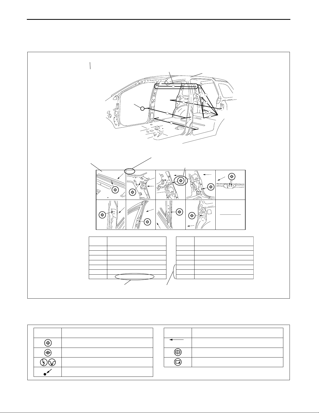
HOW TO USE THIS MANUAL
C3U000000000B01
Efficient Replacement of Body Panels
• This section contains information on the body panels in regard to the welding types, number of spot welds, and
cut-and-join locations that are necessary for panel removal and installation.
• The type of weld and position are indicated by symbols.
• Some sections have notes concerning the operation being performed. Thoroughly read and understand the
notes before carrying out any procedures.
Example
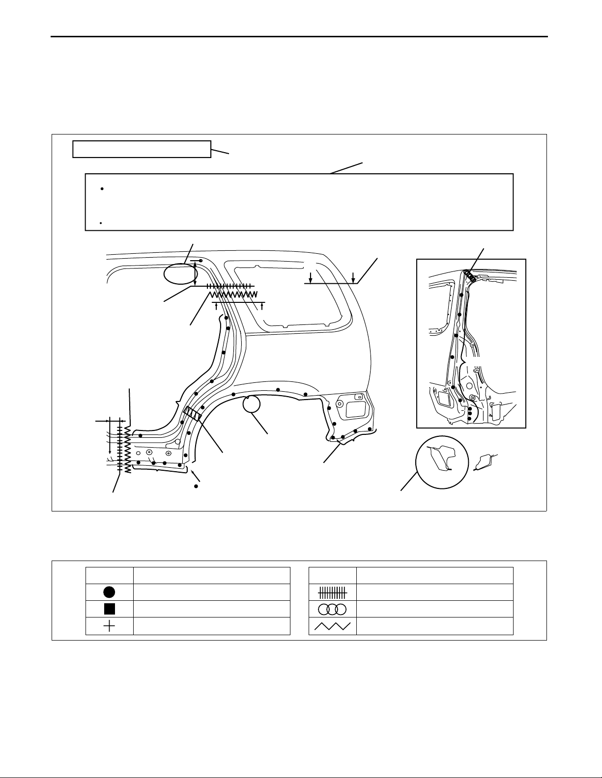
REAR FENDER PANEL REMOVAL
Caution
Avoid cutting with a flame as the insulator (shaded) is flammable.
1.The rear fender panel and wheel house are joined with glue at the wheel arch line.
NOTE
Drill the 24 weld locations indicated by (A), from the room side.
Shows a dimensions
250mm
{9.84in}
CUT-AND-JOINT LOCATION
ROUGH CUT LOCATION
Shows operation section
A
BB
Shows procedure, caution and note
Shows a cross location
A
BRAZE WELDING
17
ROUGH CUT LOCATION
30mm
{1.18in}
CUT-AND-JOINT LOCATION
(A)24
8
Shows a insulator
BOTTOM SIDE 1
19
Shows number of weld
Shows welding region
4
Shows a cross
A-A
B-B
Symbols of Panel Replacement
• The following 6 symbols are used to indicate the type of weld that is used when replacing body panels.
SYMBOL
MEANING
Spot welding
2
arc welding (plug welding)
CO
2
spot welding
CO
SYMBOL
MEANING
Continuous MIG welding (Cut-and-join location)
Braze welding
Rough cut location
MZZ2010B001
MZZ2010B002
00–00–2
Page 5
GENERAL INFORMATION
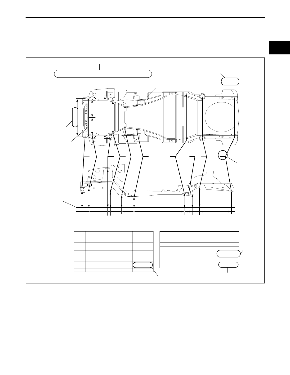
Body Dimensions (Flat-plane Dimensions)
• Flat-plane dimensions are the dimensions measured by projecting certain reference points onto a plane
surface.
• When there are no specific indications, the standard points and dimensions are symmetrical in regard to the
center of the vehicle.
• The hypothetical lines may differ according to the vehicle model.
Example
00–00
UNDERBODY FLAT-PLANE DIMENSIONS
1,030 {40.55}
Shows dimension
The dimensions on the left
and right in regard to the center
of the vehicle are different.
Shows hypothetical
standard line
Shows vehicle section
495
{19.48}
918 {38.14}
1,162 {45.78}
485
{19.09}
A
B
C
619
{24.38}
185
{7.28}
725
{28.55}
{19.27}
489
1,211
{2.19}
{47.68}
{12.40}
55
609
315
527
{24.00}
690 {27.17}
D
{20.75}
425
{16.73}
Shows outline drawing
800 {31.50}
F
E
487
{19.19}
1,240
{48.82}
When there are no specific indications, all of
units are in millimeters (mm).
mm {in}
1,220 {48.03}
G
587
98
{3.86}
H
547
{23.11}
{12.62}
{21.54}
320
1,089 {42.87}
I
624
{24.56}
716
{28.21}
J
1,060 {41.73}
Shows point
symbol
700
{27.58}
Point
symbol
Crossmember No,1 standard
A
hole
B
Front side frame standard hole
Front suspension mounting
C
block surface hole center
Front suspension mounting
D
bolt
Front frame rear standard hole
E
Designation
Hole diameter
or bolt or nut
size mm {in}
φ 16 {0.62}
φ 16 {0.62}
φ 80 {3.14}
M14 {0.55}
φ 16 {0.62}
Shows bolt size
Point
symbol
F
Front frame rear standard hole
Rear side frame standard hole
G
Link bracket
H
I
Rear suspension housing
J
Rear side frame standard hole
Designation
Hole diameter
or bolt or nut
size mm {in}
φ 18 {0.62}
φ 16 {0.62}
17 × 29.5
{0.66×1.16}
φ 12 {0.47}
φ 16 {0.62}
Shows hole diameter
00–00–3
Shows
slot
MZZ2010B003
Page 6
GENERAL INFORMATION
Body Dimensions (Straight-line Dimensions)
• Straight-line dimensions are the actual dimensions between two standard points.
• When there are no specific indications, the standard points and dimensions are symmetrical in regard to the
center of the vehicle.
Example
ROOM STRAIGHT-LINE DIMENSIONS (2)
Shows vehicle section
Shows details of the standard
point location
A
F-F
Fr
,
Fr
Shows dimension location
Shows point
symbol
F
Shows point indication
Without apostrophe:RH
With apostrophe:LH
Shows position and shape of the points
,
B-B
G-G
,
C-C
Fr
H-H
Fr
Shows outline drawing
G
9
I
8
H
,
,
,
F
10
Fr
B
1
5
C
D-D
I - I
2
6
D
7
3
A
,
H
,
,
,
E. E
4
,
E-E
Fr
Fr
11
Fr
Measured
location
1
2
3
4
5
6
7
Dimension mm {in}
1,184 {46.61}
1,064 {41.89}
919 {36.18}
690 {27.17}
1,185 {46.65}
901 {35,47}
607 {23.90}
Shows dimension
No indication are shown within the
outline drawing.
Symbols of Body Dimensions
• The following 8 symbols are used to indicate the standard points.
SYMBOL
Center of circular hole
MEANING
SYMBOL
(arrow only)
Center elliptical hole
Notch
Panel seam, bead, etc.
Measured
location
8
9
10
11
B-B'
C-C'
D-D'
Fr
Dimension mm {in}
1,642 {64.65}
1,463 {57.60}
1,667 {65.63}
1,672 {65.83}
1,037 {40.83}
1,290 {50.79}
1,208 {47.56}
MZZ2010B004
MEANING
Bolt tip
Center of rectangular-shaped hole
Edge of rectangular-shaped hole
End Of Sie
00–00–4
MZZ2010B016
Page 7
GENERAL INFORMATION
SERVICE PRECAUTIONS
C3U000000000B02
Arrangement of Workshop
• Arrangement of the workshop is important for safe and efficient work.
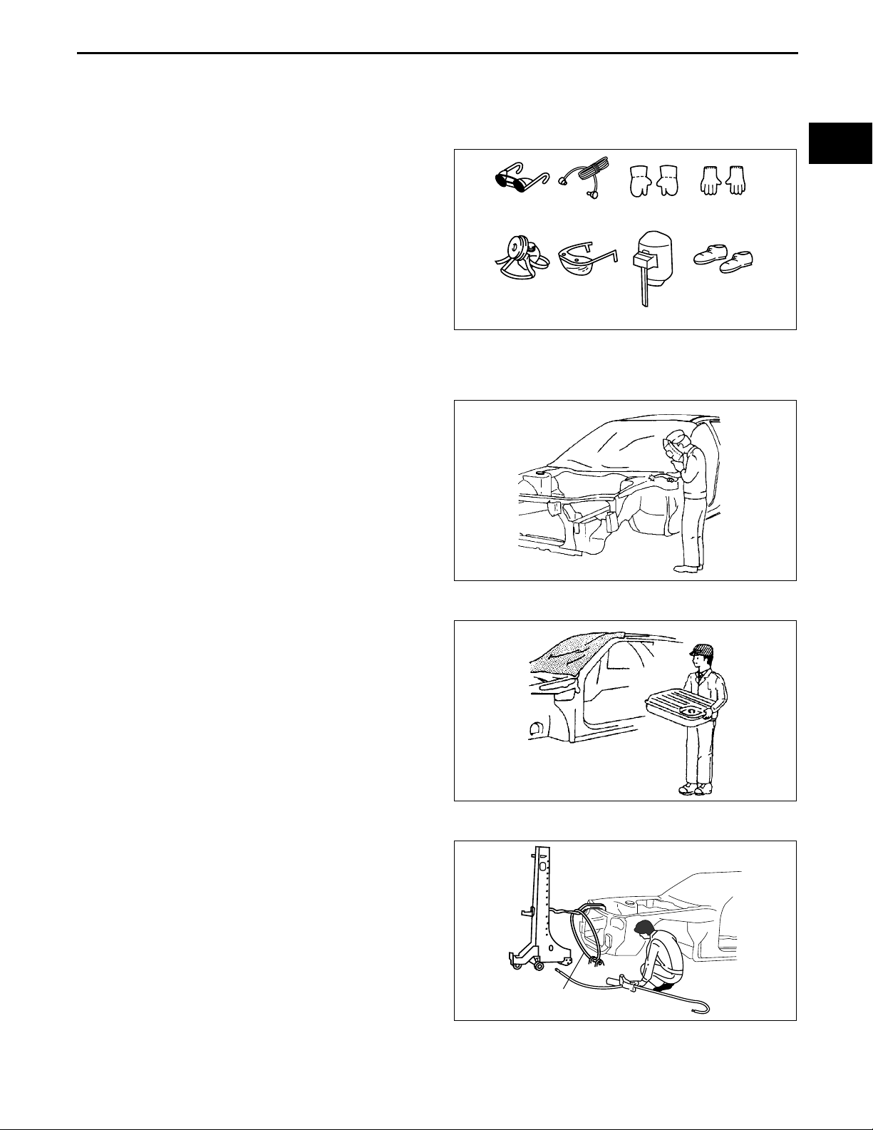
Safety Precautions
• Protective head covering and safety shoes should
always be worn. Depending upon the nature of
the work, gloves, safety glasses, ear protectors,
face shield, etc., should also be used.
Welding
glasses
Dust mask Safety glasses
Ear
protectors
Weldlng
gloves
Face shield
Cotton
gloves
Safety shoes
Vehicle Protection
• Use seat covers and floor covers.
• Use heat-resistant protective covers to protect glass areas and seats from heat or sparks during welding.
• Protect items such as moldings, garnishes, and
ornaments with tape when welding.
00–00
MZZ2036B001
Remove Dangerous Articles
• Remove the fuel tank before using an open flame
in that area. Plug connection piping to prevent
fuel leakage.
Use of Pulling Equipment
• When using pulling equipment, keep away from
the pulling area and use safety wires to prevent
accidents.
MZZ2036B002
MZZ2036B003
Safety wires
MZZ2036B004
00–00–5
Page 8
GENERAL INFORMATION
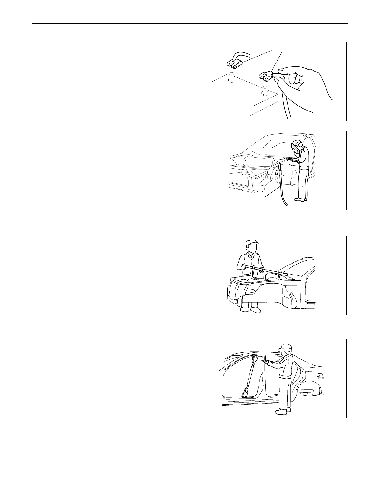
Prevent Short Circuits
• Turn the ignition switch to the LOCK position.
• Disconnect the battery cables.
• Securely connect the welding machine ground
near the welding area.
End Of Sie
Battery cable
MZZ2036B005
EFFICIENT REMOVAL OF BODY PANELS
Body Measurements
• Before removal or rough-cutting, first measure the
body at and around the damaged area against
the standard reference dimension specifications.
If there is deformation, use frame repair
equipment to make a rough correction.
Prevention of Body Deformation
• Use a clamp or a jack for removal and reinforce at
and around the rough-cutting location to prevent
deforming of the body.
Ground
MZZ2036B006
C3U000000000B03
MZJ2038B001
00–00–6
MZJ2038B002
Page 9
GENERAL INFORMATION
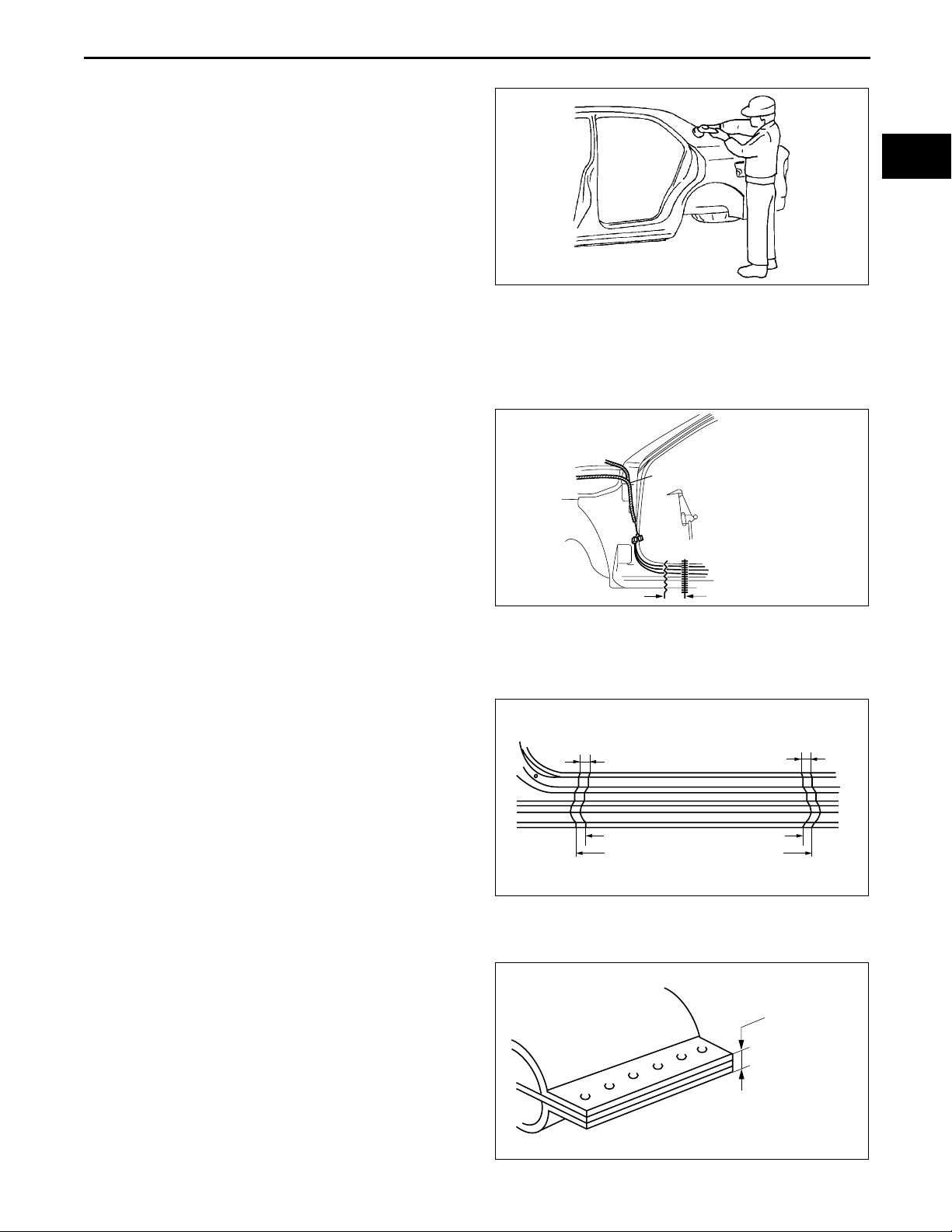
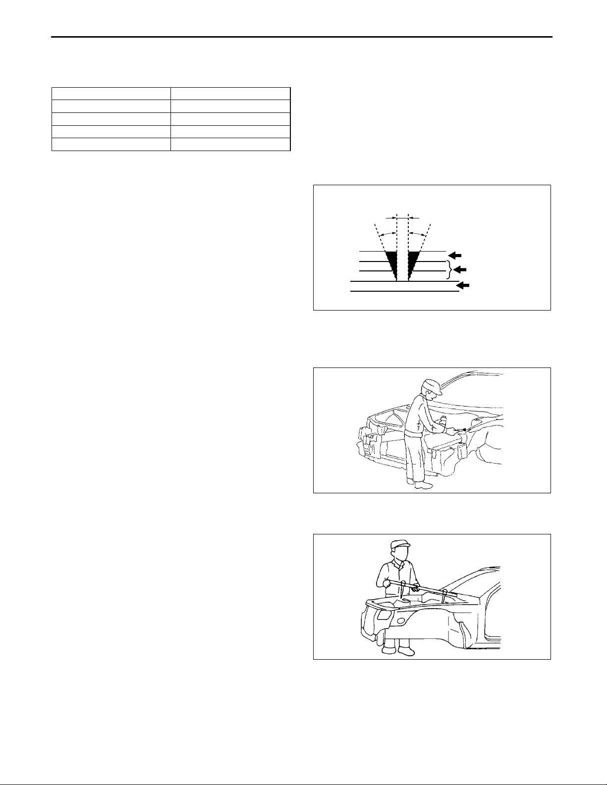
Selection of Cut-and-join Locations
• For parts where complete replacement is not
feasible, careful cutting and joining operations
should be followed. If the location to be cut is a
flat area where there is no reinforcement, the
selected cutting location should be where the
welding distortion will be minimal.
MZJ2038B003
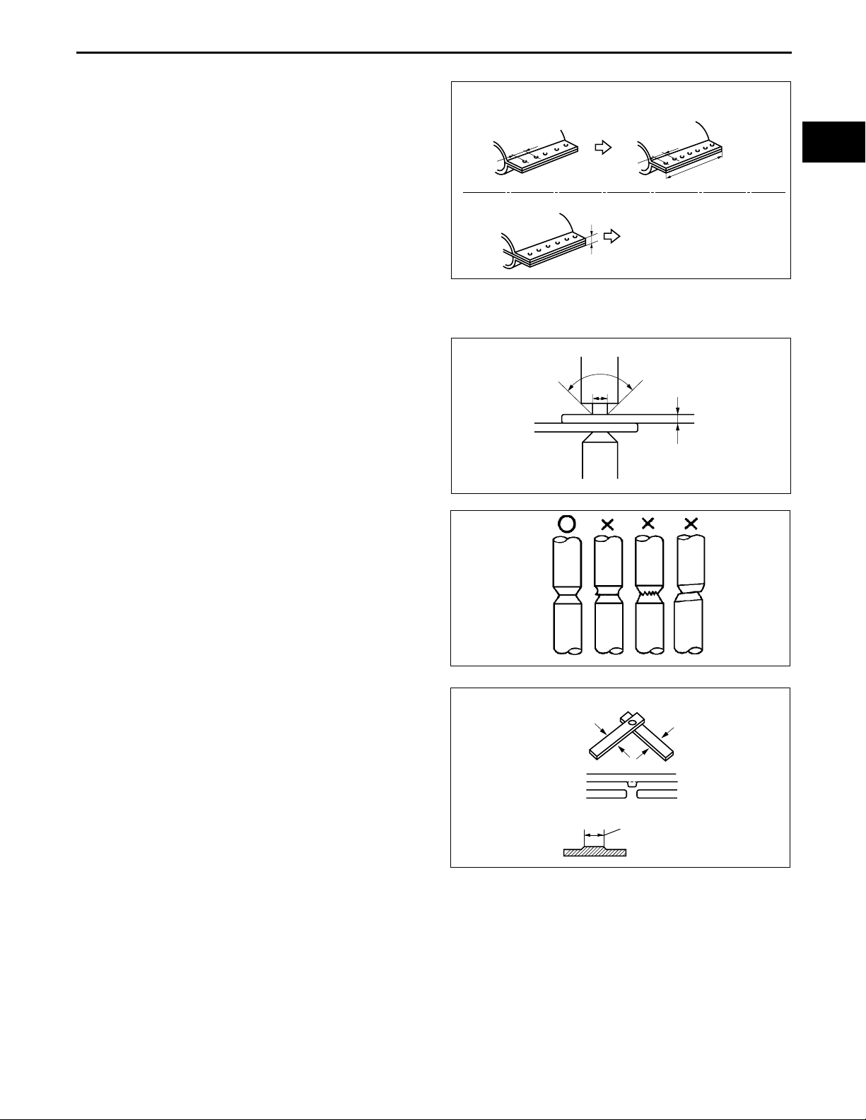
Removal of Associated Parts
• Protect moldings, garnishes, and ornaments with tape when removing associated parts.
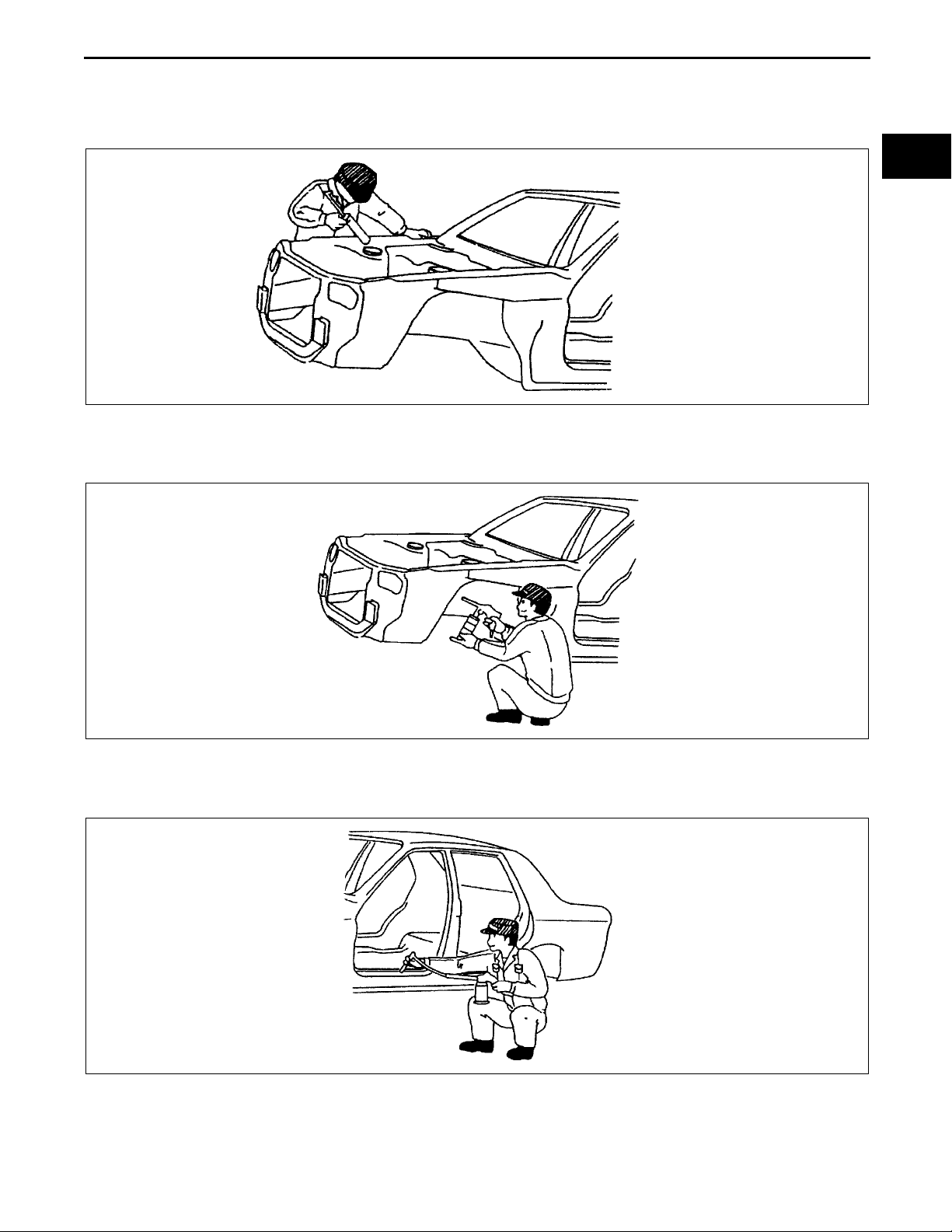
Rough Cutting of Damaged Panel
• Verify that there are no parts (such as pipes, hoses, and wiring harness) nearby or on the opposite side of a
panel which could be damaged by heat.
• For cut-and-join areas, allow for an overlap of
30—50 mm {1.18—1.97 in} and then rough-cut
the damaged panel.
End Of Sie
Wiring harness
00–00
Rough cut location
INSTALLATION PREPARATIONS
Cut-and-join location
MZZ2038B001
C3U000000000B04
Rough Cutting of New Parts
• For cut-and-join areas, allow for an overlap of 30—50 mm {1.18—1.97 in} with the remaining area on the body
side and then rough-cut the new parts.
30-50mm{1.18-1.97in}
Over lap
Body side rough cut location
New part rough cut location
30-50mm{1.18-1.97in}
Over lap
MZZ2038B002
Determination of Welding Method
• If the total thickness at the area to be welded is 3 mm {0.12 in} or more, use a CO
gas shielded-arc welder to
2
make the plug welds.
3mm
{0.12in}or more
MZZ2038B003
00–00–7
Page 10
GENERAL INFORMATION
Making Holes for CO2 Arc Welding
• For places that cannot be spot welded, make a hole for CO
(mm {in})
Panel thickness (ø) Hole diameter (ø)
0.60—0.90 {0.02—0.03} 5 {0.19}
0.91—1.20 {0.04—0.05} 6 {0.23}
1.21—1.80 {0.051—0.07} 8 {0.31}
1.81—4.50 {0.071—0.17} 10 {0.39}
• Grind the shaded section indicated in the diagram below and create a hole in the part where the 3—4 plates
are put together. Also, weld the plates together tightly so that gaps do not develop.
arc welding using a punch or drill as follows.
2
φ
10mm{0.39in}
30°
30°
Outer panel
Middie panel
Inner panel
MZZ2038B004
Application of Weld-through Primer
• For treatment against corrosion, remove the paint grease, and other material from the portion of new part and
body to be welded, and apply weld-through primer.
End Of Sie
MZJ2038B008
EFFICIENT INSTALLATION OF BODY PANELS
Checking Preweld Measurements And Watching
• Align to the standard reference dimensions,
based upon the body dimensions illustration, so
that new parts are installed in the correct position.
C3U000000000B05
00–00–8
MZJ2038B009
Page 11
GENERAL INFORMATION
Welding Notes
• For the number of weld points, welding should be
performed in accordance with the following
reference standards.
Spot Welding Notes
• The shape of the spot welder tip is D=(2×t)+3. If
the upper panel thickness is different from that of
the under panel, adjust to the thinner one.
Spot welding
Original weld
Pitch: 50mm{1.97in}
2
CO
arc welding
Original spot weld
Repair weld
Pitch: within 35mm{1.38in}
Original number of welds x 1.3 or more
If 3mm
{0.12in} or more
Original number of welds
or more
70 - 120°
D
Repair weld
MZZ2038B005
t
00–00
• Because the weld strength is affected by the
shape of the spot welder tip, the optimum
condition of the tip should always be maintained.
• Spot welds should be made at points other than
the originally welded points.
• Before spot welding, make a trial weld using the
same material as the body panel to check the
weld strength.
MZZ2038B009
MZJ2038B012
Test piece method
Nagget diameter
:4/5 of tip
MZZ2038B006
00–00–9
Page 12

GENERAL INFORMATION
Checking Weld Strength
• Installation locations of the engine, chassis, and
seat belts are designated as important safety
locations for weld strength. Check weld strength
by driving a chisel between the panels at every
fourth or fifth weld spot, and every tenth regular
weld location.
• Drive the chisel between the panels according to
the number of panels as shown below.
• To determine weld strength, drive the chisel
between the panel and check whether the panels
come apart. If the panels come apart, make
another weld near the original weld.
• Restore the shape of the checked area.
End Of Sie
Chisel dimensions
25mm
{0.98in}
Within 5mm
{0.20in}
Two panels
Three panels
20°
8mm{0.31in}
Weld location
Within 5mm
{0.20in}
MZZ2038B007
Weld location
One location
Weld location
Four panels
Two location
Weld location
Three location
MZZ2038B008
00–00–10
Page 13
GENERAL INFORMATION
ANTICORROSION, SOUND INSULATION, AND VIBRATION INSULATION
Body Sealing
• Apply body sealer where necessary.
• For locations where application of body sealer is difficult after installation, apply it before installation.
Application of Undercoating
• Apply an undercoat to the required location of the body.
C3U000000000B06
00–00
YMU980PAR
Application of Rust Inhibitor
• Apply rust inhibitor (wax, oil, etc.) to the back of the welded areas.
YMU980PAS
YMU980PAT
00–00–11
Page 14
GENERAL INFORMATION
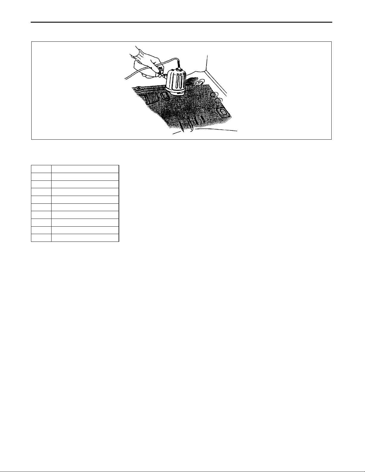
Application of Floor Silencer
• Apply floor silencer by heating with an infrared ray lamp.
End Of Sie
ABBREVIATION
CM Control module
Ctr Center
DSC Dynamic stability control
Fr Front
HU Hydraulic unit
LH Left
M Metallic
MC Mica
RH Right
Rr Rear
YMU980PAU
C3U000000000B07
End Of Sie
00–00–12
Page 15
BODY & ACCESSORIES
Toc of SCT
CONSTRUCTION . . . . . . . . . . . 09-80A
PANEL REPLACEMENT . . . . .09-80B
WATER-PROOF AND RUST
PREVENTIVE TREATMENT. . 09-80C
Toc of SCT
09–80A BODY STRUCTURE [CONSTRUCTION]
DIMENSIONS . . . . . . . . . . . . . . 09-80D
PLASTIC BODY PARTS . . . . . 09-80E
09
SECTION
09–80A
BODY COMPONENTS CONSTRUCTION09–80A–2
4SD . . . . . . . . . . . . . . . . . . . . . . . . . . . . 09–80A–2
End of Toc
5HB . . . . . . . . . . . . . . . . . . . . . . . . . . . 09–80A–5
09–80A–1
Page 16
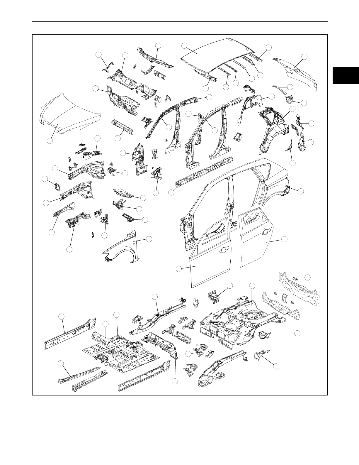
BODY STRUCTURE [CONSTRUCTION]
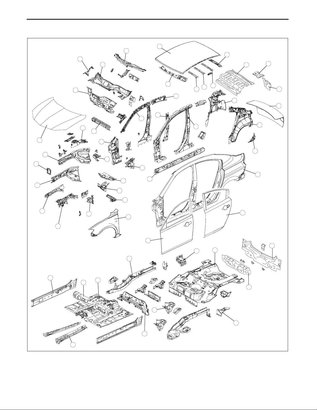
BODY COMPONENTS CONSTRUCTION
4SD
16
17
15
8
14
1
20
3
10
2
4
12
11
18
21
19
25
22
34
29
23
30
24
31
32
33
26
35
C3U098007000B01
36
37
38
27
28
39
13
5
7
9
40
6
41
53
50
51
48
42
44
45
52
47
49
46
43
.
B3U0980B041
09–80A–2
Page 17
BODY STRUCTURE [CONSTRUCTION]
x:Applied
-:Not applied
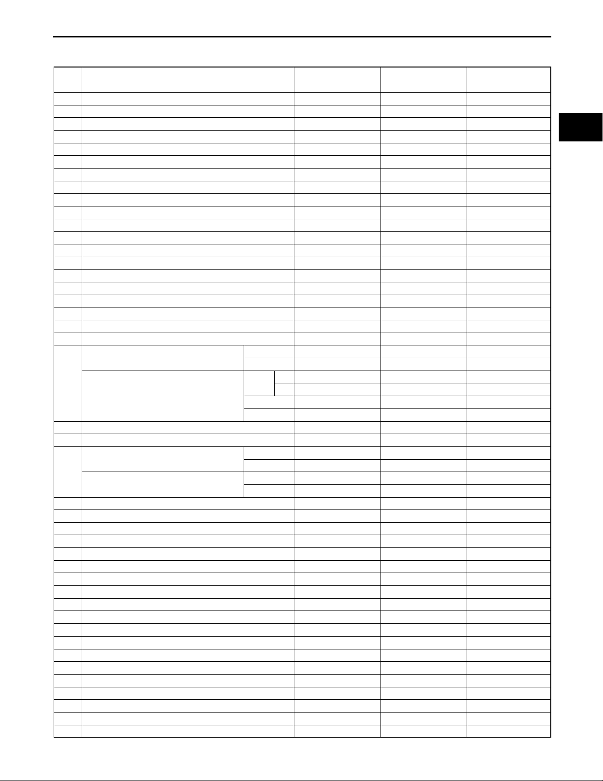
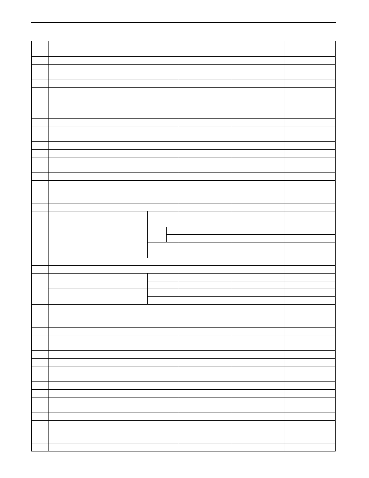
No. Part Name High- tension steel Rust proof steel
1 Hood - x 0.70 {0.028}
2 Front bumper bracket x x 2.90 {0.114}
3 Front side frame (inner) x x 1.60 {0.063}
4 Front side frame (outer) x x 1.60 {0.063}
5 Apron reinforcement (lower) - x 0.70 {0.028}
6 Apron reinforcement (upper) - x 1.00 {0.039}
7 Shroud side panel x x 1.00 {0.039}
8 Suspension housing - x 2.60 {0.102}
9 Front fender panel x x 0.65 {0.026}
10 Side member deck - x 1.80 {0.071}
11 Front frame rear reinforcement x x 0.80 {0.031}
12 Front frame (rear) x x 1.80 {0.071}
13 Torque box - x 1.60 {0.063}
14 Dash lower member x x 1.40 {0.055}
15 Dash lower panel x 0.80 {0.031}
16 Wiper bracket - x 1.40 {0.055}
17 Dash upper panel - x 0.85 {0.033}
18 Cowl panel - x 0.80 {0.031}
19 Cowl side reinforcement - x 0.70 {0.028}
20 Hinge pillar (inner) x x 1.60 {0.063}
Front pillar (inner)
21
Center pillar (inner)
22 Center pillar reinforcement (inner) x - 1.80 {0.071}
23 Roof rail (inner, rear) x - 1.00 {0.039}
Front pillar reinforcement
24
Center pillar reinforcement
25 Side sill reinforcement x - 1.40 {0.055}
26 Wheel house (inner) - x 0.70 {0.028}
27 Rear pillar (inner) - x 0.65 {0.026}
28 Rear fender lower panel - x 0.70 {0.028}
29 Front header - - 0.65 {0.026}
30 Roof reinforcement (front) - - 0.55 {0.021}
31 Roof reinforcement center - - 1.00 {0.039}
32 Roof reinforcement (rear) - - 1.00 {0.039}
33 Rear header - - 0.70 {0.028}
34 Roof panel - - 0.70 {0.028}
35 Package tray - - 0.60 {0.024}
36 Rear fender rain rail - x 0.70 {0.028}
37 Corner plate - x 0.70 {0.028}
38 Trunk lid panel x x 0.70 {0.028}
39 Side panel (outer) - x 0.70 {0.028}
40 Rear door - x 0.65 {0.026}
41 Front door - x 0.70 {0.028}
42 Side sill (inner) x x 1.40 {0.055}
43 Front B frame x x 0.90 {0.035}
LH x - 1.40 {0.055}
RH x - 1.60 {0.063}
Upper
Center x - 1.20 {0.047}
Lower x - 1.00 {0.039}
Upper x - 1.80 {0.071}
Lower x - 1.80 {0.071}
Upper x - 1.40 {0.055}
Lower x - 1.20 {0.047}
LH x - 1.60 {0.063}
RH x - 1.80 {0.071}
Thickness
(mm) {in}
09–80A
09–80A–3
Page 18
BODY STRUCTURE [CONSTRUCTION]
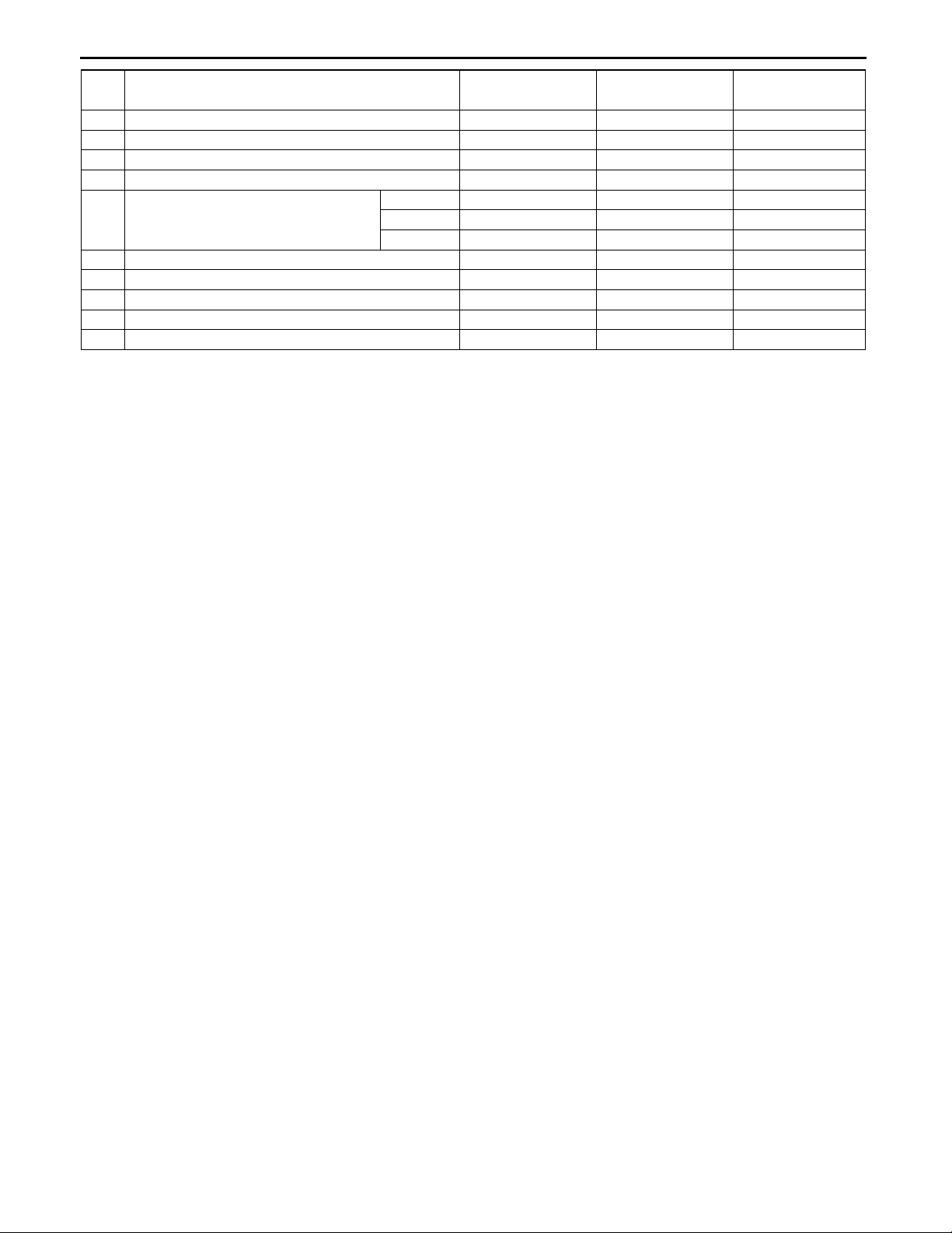
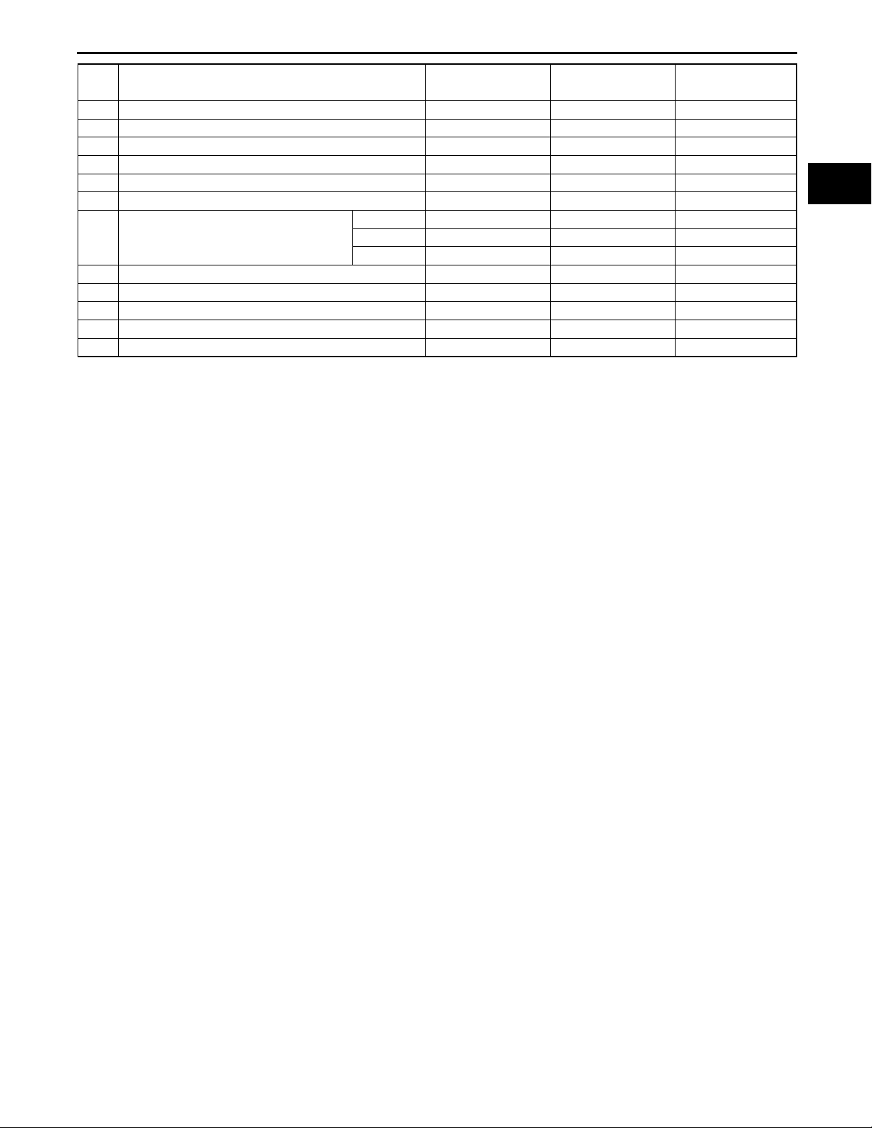
No. Part Name High- tension steel Rust proof steel
44 Crossmember No.2 x - 1.20 {0.047}
45 Front floor pan - x 0.70 {0.028}
46 Crossmember No.3 x x 1.60 {0.063}
47 Crossmember No.4 gusset - x 1.40 {0.055}
Front x x 2.00 {0.079}
48 Rear side frame
49 Crossmember No.3 (front) - x 1.60 {0.063}
50 Suspension housing - x 0.75 {0.030}
51 Rear floor pan - x 2.00 {0.079}
52 Rear end member - - 0.60 {0.024}
53 Rear end panel - x 0.60 {0.024}
Center x x 2.60 {0.102}
Rear x x 1.80 {0.071}
Thickness
(mm) {in}
09–80A–4
Page 19
5HB
BODY STRUCTURE [CONSTRUCTION]
15
16
18
17
38
33
23
34
35
36
37
39
40
09–80A
28
26
29
27
22
21
1
8
14
24
30
31
20
32
3
10
2
19
25
41
11
4
12
13
5
7
9
42
6
43
55
53
52
50
44
47
46
54
49
45
51
48
B3U0980B043
.
09–80A–5
Page 20
BODY STRUCTURE [CONSTRUCTION]
x:Applied
-:Not applied
No. Part Name High- tension steel Rust proof steel
1 Hood x x 0.70 {0.028}
2 Front bumper bracket x x 2.90 {0.114}
3 Front side frame (inner) x x 1.60 {0.063}
4 Front side frame (outer) x x 1.60 {0.063}
5 Apron reinforcement (lower) - x 0.70 {0.028}
6 Apron reinforcement (upper) - x 1.00 {0.039}
7 Shroud side panel x x 1.00 {0.039}
8 Suspension housing - x 2.60 {0.102}
9 Front fender panel x x 0.65 {0.026}
10 Side member deck - x 1.80 {0.071}
11 Front frame rear reinforcement x x 0.80 {0.031}
12 Front frame (rear) x x 1.80 {0.071}
13 Torque box - x 1.60 {0.063}
14 Dash lower member x x 1.40 {0.055}
15 Dash lower panel x 0.80 {0.031}
16 Wiper bracket - x 1.40 {0.055}
17 Dash upper panel - x 0.85 {0.033}
18 Cowl panel - x 0.80 {0.031}
19 Cowl side reinforcement - x 0.70 {0.028}
20 Hinge pillar (inner) x x 1.60 {0.063}
Front pillar (inner)
21
Center pillar (inner)
22 Center pillar reinforcement (inner) x - 1.80 {0.071}
23 Roof rail (inner, rear) x - 1.00 {0.039}
Front pillar reinforcement
24
Center pillar reinforcement
25 Side sill reinforcement x - 1.40 {0.055}
26 Wheel house (inner) - x 0.70 {0.028}
27 Rear pillar (inner) - x 0.65 {0.026}
28 Rear pillar (outer) - x 0.70 {0.028}
29 Corner plate - x 0.70 {0.028}
30 Rear side panel - - 0.70 {0.028}
31 Rear pillar reinforcement - - 0.70 {0.028}
32 Rear fender lower panel - x 0.70 {0.028}
33 Front header - - 0.65 {0.026}
34 Roof reinforcement (front) - - 0.55 {0.021}
35 Roof reinforcement center (front) - - 1.00 {0.039}
36 Roof reinforcement center (rear) - - 0.75 {0.030}
37 Roof reinforcement (rear) - - 0.55 {0.021}
38 Rear header - - 0.75 {0.030}
39 Roof panel - - 0.75 {0.030}
40 Liftgate panel - x 0.70 {0.028}
41 Side panel (outer) - x 0.70 {0.028}
42 Rear door - x 0.65 {0.026}
43 Front door x x 0.70 {0.028}
LH x - 1.40 {0.055}
RH x - 1.60 {0.063}
Upper
Center x - 1.20 {0.047}
Lower x - 1.00 {0.039}
Upper x - 1.80 {0.071}
Lower x - 1.80 {0.071}
Upper x - 1.40 {0.055}
Lower x - 1.20 {0.047}
LH x - 1.60 {0.063}
RH x - 1.80 {0.071}
Thickness
(mm) {in}
09–80A–6
Page 21
BODY STRUCTURE [CONSTRUCTION]
No. Part Name High- tension steel Rust proof steel
44 Side sill (inner) x x 1.40 {0.055}
45 Front B frame x x 0.90 {0.035}
46 Crossmember No.2 x - 1.20 {0.047}
47 Front floor pan - x 0.70 {0.028}
48 Crossmember No.3 x x 1.60 {0.063}
49 Crossmember No.4 gusset - x 1.40 {0.055}
Front x x 2.00 {0.079}
50 Rear side frame
51 Crossmember No.3 (front) - x 1.60 {0.063}
52 Rear floor pan - x 0.75 {0.030}
53 Suspension housing - x 2.00 {0.079}
54 Rear end member - - 1.20 {0.047}
55 Rear end panel - x 0.60 {0.024}
Center x x 2.60 {0.102}
Rear x x 1.80 {0.071}
Thickness
(mm) {in}
End Of Sie
09–80A
09–80A–7
Page 22

BODY STRUCTURE [PANEL REPLACEMENT]
09–80B BODY STRUCTURE [PANEL REPLACEMENT]
FRONT BUMPER BRACKET
REMOVAL . . . . . . . . . . . . . . . . . . . . . . . 09–80B–2
FRONT BUMPER BRACKET
INSTALLATION. . . . . . . . . . . . . . . . . . . 09–80B–3
SHROUD SIDE PANEL REMOVAL . . . . 09–80B–4
SHROUD SIDE PANEL
INSTALLATION. . . . . . . . . . . . . . . . . . . 09–80B–5
COWL SIDE REINFORCEMENT
REMOVAL . . . . . . . . . . . . . . . . . . . . . . . 09–80B–6
COWL SIDE REINFORCEMENT
INSTALLATION. . . . . . . . . . . . . . . . . . . 09–80B–7
APRON REINFORCEMENT (LOWER)
REMOVAL . . . . . . . . . . . . . . . . . . . . . . . 09–80B–8
APRON REINFORCEMENT (LOWER)
INSTALLATION. . . . . . . . . . . . . . . . . . . 09–80B–9
APRON REINFORCEMENT (PARTIAL
CUTTING) REMOVAL . . . . . . . . . . . . . . 09–80B–10
APRON REINFORCEMENT (PARTIAL
CUTTING) INSTALLATION. . . . . . . . . . 09–80B–12
WHEEL APRON PANEL (FRONT)
REMOVAL . . . . . . . . . . . . . . . . . . . . . . . 09–80B–14
WHEEL APRON PANEL (FRONT)
INSTALLATION. . . . . . . . . . . . . . . . . . . 09–80B–15
FRONT SIDE FRAME COMPONENT
REMOVAL . . . . . . . . . . . . . . . . . . . . . . . 09–80B–15
FRONT SIDE FRAME COMPONENT
INSTALLATION. . . . . . . . . . . . . . . . . . . 09–80B–19
FRONT SIDE FRAME (PARTIAL
CUTTING) REMOVAL . . . . . . . . . . . . . . 09–80B–22
FRONT SIDE FRAME (PARTIAL
CUTTING) INSTALLATION. . . . . . . . . . 09–80B–22
TORQUE BOX REMOVAL . . . . . . . . . . . 09–80B–25
TORQUE BOX INSTALLATION . . . . . . . 09–80B–26
FRONT FRAME (REAR) REMOVAL . . . 09–80B–27
FRONT FRAME (REAR)
INSTALLATION. . . . . . . . . . . . . . . . . . . 09–80B–28
FRONT PILLAR REMOVAL . . . . . . . . . . 09–80B–28
FRONT PILLAR INSTALLATION . . . . . . 09–80B–32
CENTER PILLAR REMOVAL . . . . . . . . . 09–80B–35
CENTER PILLAR INSTALLATION . . . . . 09–80B–37
REAR FENDER PANEL REMOVAL . . . . 09–80B–40
4SD . . . . . . . . . . . . . . . . . . . . . . . . . . . 09–80B–40
5HB . . . . . . . . . . . . . . . . . . . . . . . . . . . . 09–80B–41
REAR FENDER PANEL
INSTALLATION . . . . . . . . . . . . . . . . . . . 09–80B–42
4SD . . . . . . . . . . . . . . . . . . . . . . . . . . . . 09–80B–42
5HB . . . . . . . . . . . . . . . . . . . . . . . . . . . . 09–80B–43
REAR FENDER LOWER PANEL
REMOVAL . . . . . . . . . . . . . . . . . . . . . . . 09–80B–44
4SD . . . . . . . . . . . . . . . . . . . . . . . . . . . . 09–80B–44
5HB . . . . . . . . . . . . . . . . . . . . . . . . . . . . 09–80B–45
REAR FENDER LOWER PANEL
INSTALLATION . . . . . . . . . . . . . . . . . . . 09–80B–46
4SD . . . . . . . . . . . . . . . . . . . . . . . . . . . . 09–80B–46
5HB . . . . . . . . . . . . . . . . . . . . . . . . . . . . 09–80B–47
SIDE SILL PANEL REMOVAL. . . . . . . . . 09–80B–48
SIDE SILL PANEL INSTALLATION. . . . .09–80B–49
REAR END PANEL REMOVAL . . . . . . . . 09–80B–50
4SD . . . . . . . . . . . . . . . . . . . . . . . . . . . . 09–80B–50
5HB . . . . . . . . . . . . . . . . . . . . . . . . . . . . 09–80B–51
REAR END PANEL INSTALLATION . . . . 09–80B–52
4SD . . . . . . . . . . . . . . . . . . . . . . . . . . . . 09–80B–52
5HB . . . . . . . . . . . . . . . . . . . . . . . . . . . . 09–80B–53
REAR FENDER RAIN RAIL AND
CORNER PLATE REMOVAL . . . . . . . . . 09–80B–54
4SD . . . . . . . . . . . . . . . . . . . . . . . . . . . . 09–80B–54
5HB . . . . . . . . . . . . . . . . . . . . . . . . . . . . 09–80B–55
REAR FENDER RAIN RAIL AND
CORNER PLATE INSTALLATION . . . . 09–80B–56
4SD . . . . . . . . . . . . . . . . . . . . . . . . . . . . 09–80B–56
5HB . . . . . . . . . . . . . . . . . . . . . . . . . . . . 09–80B–57
REAR FLOOR PAN REMOVAL . . . . . . . . 09–80B–58
REAR FLOOR PAN INSTALLATION. . . . 09–80B–60
REAR SIDE FRAME (PARTIAL CUTTING)
REMOVAL . . . . . . . . . . . . . . . . . . . . . . . 09–80B–62
REAR SIDE FRAME (PARTIAL CUTTING)
INSTALLATION . . . . . . . . . . . . . . . . . . . 09–80B–63
ROOF PANEL REMOVAL . . . . . . . . . . . . 09–80B–64
4SD . . . . . . . . . . . . . . . . . . . . . . . . . . . . 09–80B–64
5HB . . . . . . . . . . . . . . . . . . . . . . . . . . . . 09–80B–65
ROOF PANEL INSTALLATION . . . . . . . . 09–80B–66
4SD . . . . . . . . . . . . . . . . . . . . . . . . . . . . 09–80B–66
5HB . . . . . . . . . . . . . . . . . . . . . . . . . . . . 09–80B–67
09–80B
End of Toc
09–80B–1
Page 23
BODY STRUCTURE [PANEL REPLACEMENT]
FRONT BUMPER BRACKET REMOVAL
1. Remove the front bumper bracket.
Caution
•••• Only the procedure for the left side is described. The shape for the right side is different.
FRONT BUMPER BRACKET
C3U098053896B01
End Of Sie
09–80B–2
B3E0980B047
Page 24
BODY STRUCTURE [PANEL REPLACEMENT]
FRONT BUMPER BRACKET INSTALLATION
C3U098053896B02
1. When installing new parts, measure and adjust the body as necessary to conform with standard dimensions.
2. After temporarily installing new parts, make sure the related parts fit properly.
FRONT BUMPER BRACKET
09–80B
End Of Sie
B3E0980B048
09–80B–3
Page 25
BODY STRUCTURE [PANEL REPLACEMENT]
SHROUD SIDE PANEL REMOVAL
1. Remove the shroud side panel.
1
2
C3U098053140B01
3
1
3
SHROUD SIDE PANEL LH
1
1
2
3
4
End Of Sie
09–80B–4
SHROUD SIDE PANEL RH
B3E0980B049
Page 26
BODY STRUCTURE [PANEL REPLACEMENT]
SHROUD SIDE PANEL INSTALLATION
C3U098053140B02
1. When installing new parts, measure and adjust the body as necessary to conform with standard dimensions.
2. Drill holes for plug welds before installing new parts.
3. After temporarily installing new parts, make sure the related parts fit properly.
1
2
2
1
3
1
09–80B
SHROUD SIDE PANEL LH
1
1
2
3
4
End Of Sie
SHROUD SIDE PANEL RH
B3E0980B050
09–80B–5
Page 27
BODY STRUCTURE [PANEL REPLACEMENT]
COWL SIDE REINFORCEMENT REMOVAL
1. Remove the cowl side reinforcement.
Caution
•••• Be careful not to damage the windshield when drilling the 2 locations indicated by (A).
(A)2
4
1
2
C3U098053290B01
7
End Of Sie
COWL SIDE REINFORCEMENT
2
8
B3E0980B051
09–80B–6
Page 28
BODY STRUCTURE [PANEL REPLACEMENT]
COWL SIDE REINFORCEMENT INSTALLATION
C3U098053290B02
1. When installing new parts, measure and adjust the body as necessary to conform with standard dimensions.
2. Drill holes for plug welds before installing new parts.
3. After temporarily installing new parts, make sure the related parts fit properly.
2
4
1
7
2
09–80B
End Of Sie
COWL SIDE REINFORCEMENT
2
8
B3E0980B052
09–80B–7
Page 29
BODY STRUCTURE [PANEL REPLACEMENT]
APRON REINFORCEMENT (LOWER) REMOVAL
1. Remove the apron reinforcement (lower).
3
C3U098053260B01
APRON REINFORCEMENT (LOWER)
10
End Of Sie
12
B3E0980B053
09–80B–8
Page 30
BODY STRUCTURE [PANEL REPLACEMENT]
APRON REINFORCEMENT (LOWER) INSTALLATION
C3U098053260B02
1. When installing new parts, measure and adjust the body as necessary to conform with standard dimensions.
2. Drill holes for plug welds before installing new parts.
3. After temporarily installing new parts, make sure the related parts fit properly.
3
APRON REINFORCEMENT (LOWER)
10
09–80B
End Of Sie
12
B3E0980B054
09–80B–9
Page 31

BODY STRUCTURE [PANEL REPLACEMENT]
APRON REINFORCEMENT (PARTIAL CUTTING) REMOVAL
1. Rough cut at the locations shown in the figure to remove damaged parts.
2. Remove the apron reinforcement.
ROUGH CUT LOCATION FOR
APRON REINFORCEMENT
C3U098053260B03
CUT-AND-JOIN LOCATION
APRON REINFORCEMENT
(LOWER)
50mm {1.97 in}
200mm {7.87 in}
120mm {4.72 in}
APRON REINFORCEMENT
(LOWER)
CUT-AND-JOIN LOCATION FOR APRON
REINFORCEMENT (UPPER)
APRON REINFORCEMENT
(UPPER)
09–80B–10
B3E0980B055
Page 32

BODY STRUCTURE [PANEL REPLACEMENT]
APRON REINFORCEMENT
5
3
09–80B
End Of Sie
B3E0980B056
09–80B–11
Page 33

BODY STRUCTURE [PANEL REPLACEMENT]
APRON REINFORCEMENT (PARTIAL CUTTING) INSTALLATION
C3U098053260B04
1. When installing new parts, measure and adjust the body as necessary to conform with standard dimensions.
2. Drill holes for plug welds before installing new parts.
3. After temporarily installing new parts, make sure the related parts fit properly.
CUT-AND-JOIN LOCATION FOR
APRON REINFORCEMENT (LOWER)
50mm {1.97 in}
120mm {4.72 in}
APRON REINFORCEMENT
(LOWER)
CUT-AND-JOIN LOCATION FOR
APRON REINFORCEMENT (UPPER)
3
APRON REINFORCEMENT
(UPPER)
09–80B–12
B3E0980B057
Page 34

BODY STRUCTURE [PANEL REPLACEMENT]
APRON REINFORCEMENT
5
7
09–80B
End Of Sie
B3E0980B058
09–80B–13
Page 35

BODY STRUCTURE [PANEL REPLACEMENT]
WHEEL APRON PANEL (FRONT) REMOVAL
1. Remove the wheel apron panel (front).
4
6
C3U098053210B01
DRIVER,S SIDE: 4
WHEEL APRON PANEL (FRONT)
End Of Sie
ENGINE MOUNT
REINFORCEMENT
4
B3E0980B059
09–80B–14
Page 36

BODY STRUCTURE [PANEL REPLACEMENT]
WHEEL APRON PANEL (FRONT) INSTALLATION
C3U098053210B02
1. When installing new parts, measure and adjust the body as necessary to conform with standard dimensions.
2. Drill holes for plug welds before installing new parts.
3. After temporarily installing new parts, make sure the related parts fit properly.
4
DRIVER,S SIDE: 4
WHEEL APRON PANEL (FRONT)
6
09–80B
End Of Sie
ENGINE MOUNT
REINFORCEMENT
4
B3E0980B060
09–80B–15
Page 37

BODY STRUCTURE [PANEL REPLACEMENT]
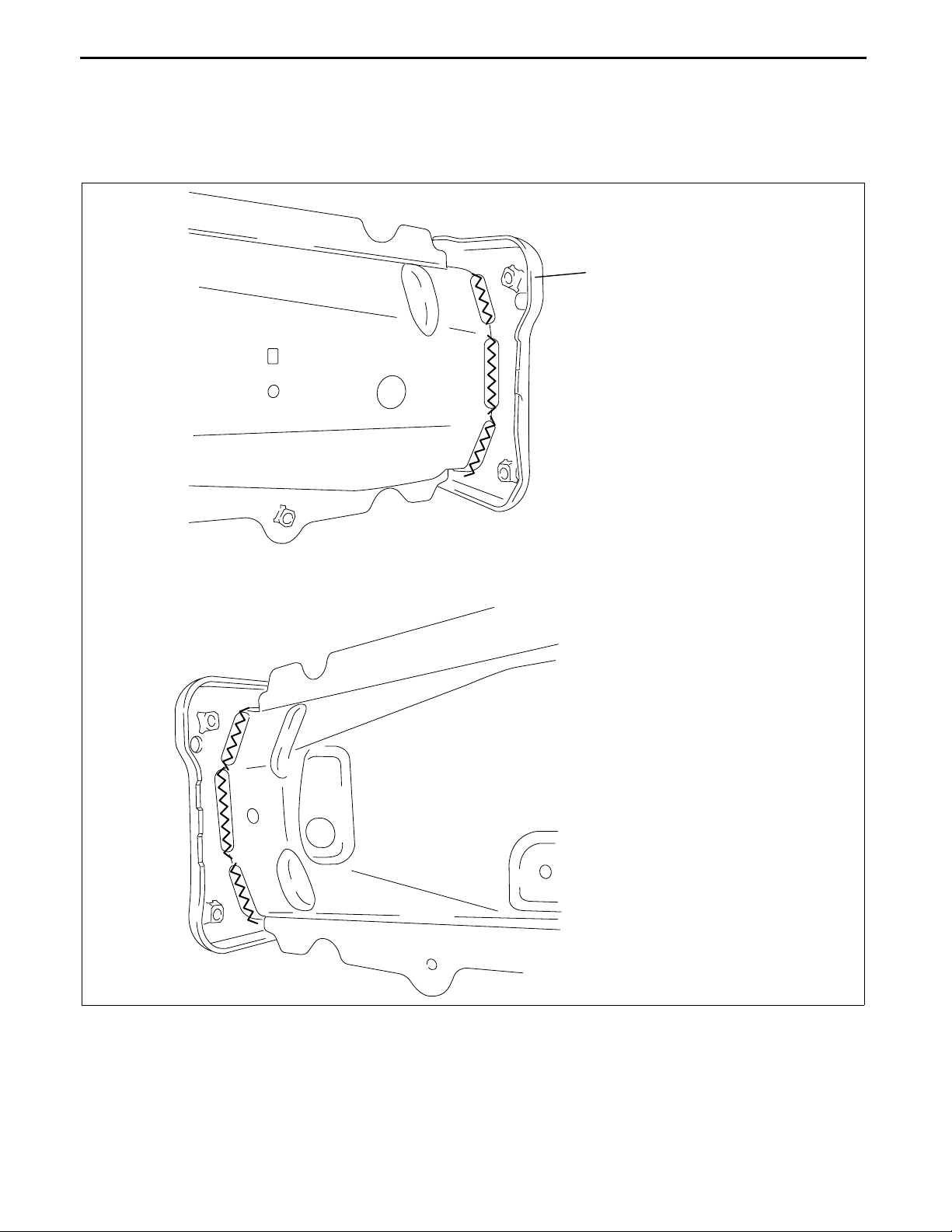
FRONT SIDE FRAME COMPONENT REMOVAL
1. Drill the 26 locations indicated by (A).
(A)4
(A)4
C3U098053300B01
SIDE MEMBER DECK
(A)4
(A)5
FRONT SIDE FRAME
(A)9
B3E0980B061
09–80B–16
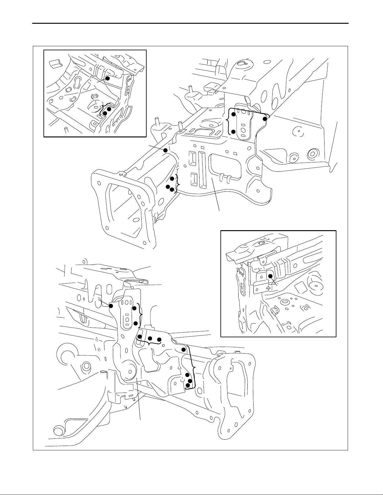
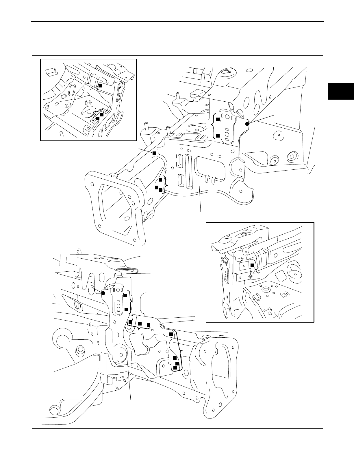
Page 38

BODY STRUCTURE [PANEL REPLACEMENT]
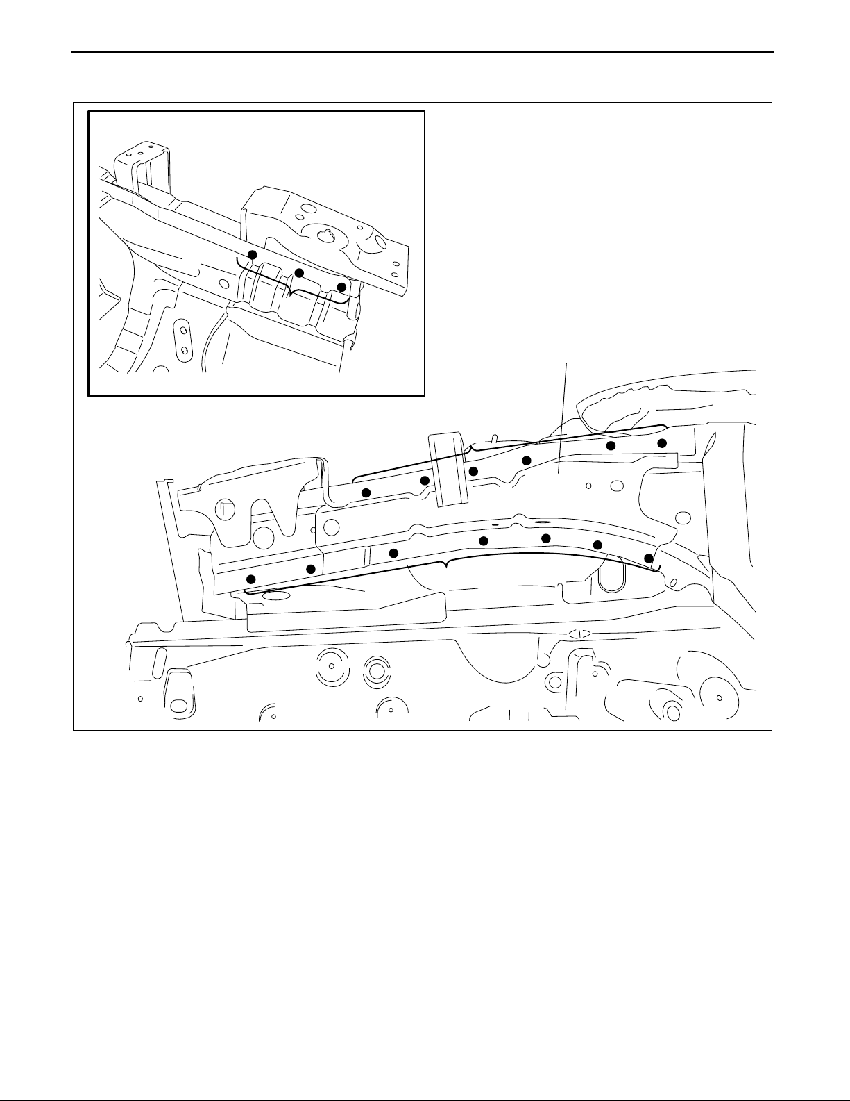
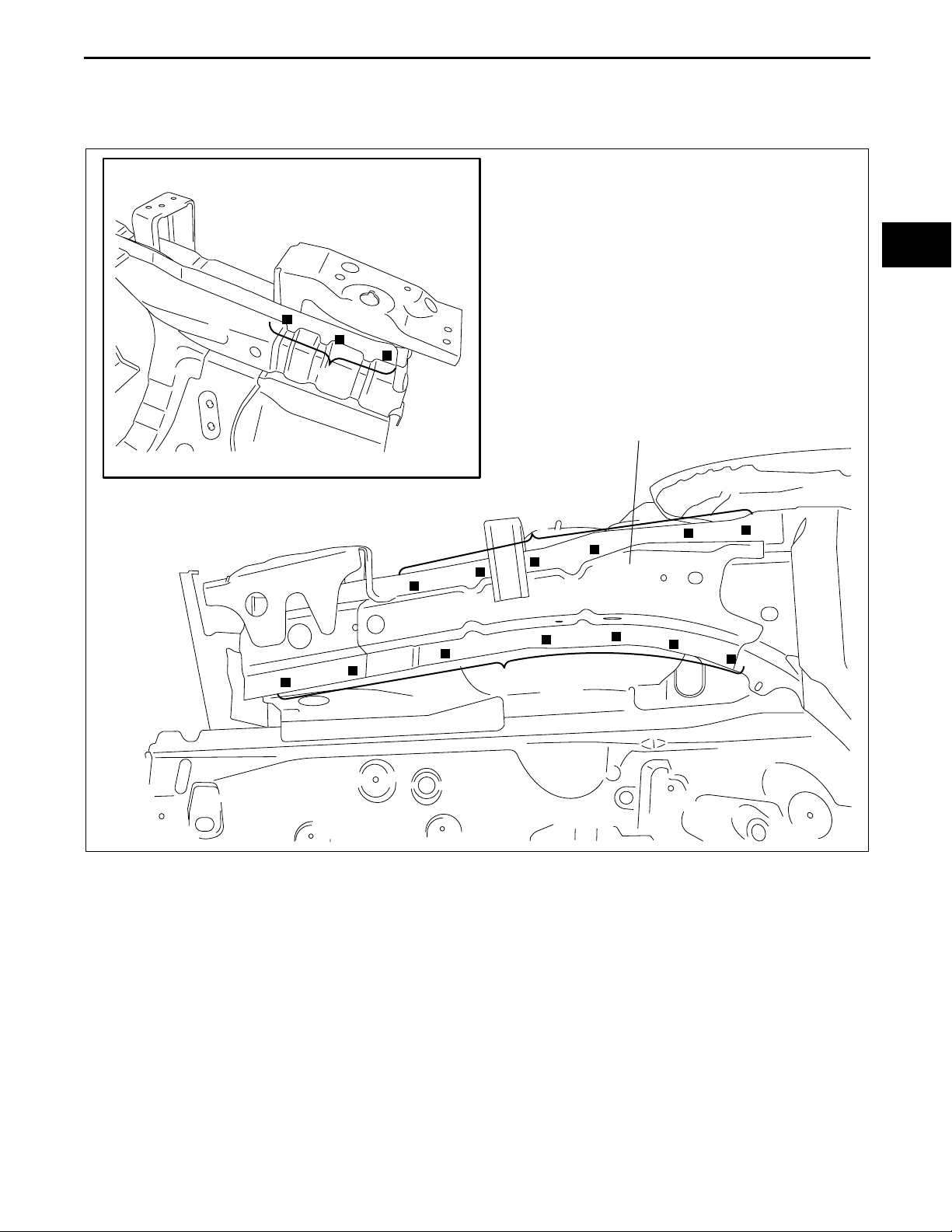
2. Drill the 65 locations indicated by (B), 4 locations on the driver’s side indicated by (C), and 3 locations on the
passenger’s side.
3. Drill the 5 locations indicated by (D) from the bottom.
4. Drill the 1 location indicated by (E) from the bottom, as it cannot be seen from the interior.
(B)5
(B)10
(B)3
(B)11
(B)7
(B)3
(C)
DRIVER,S SIDE: 4
PASSENGER,S SIDE: 3
(B)6
(B)6
(B)14
09–80B
(D)3
(D)2
(E)1
B3E0980B062
09–80B–17
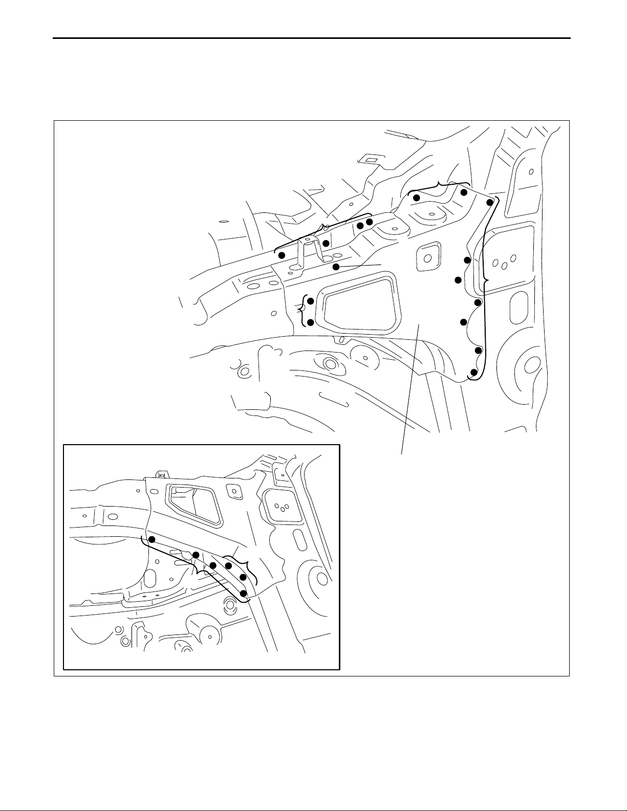
Page 39

BODY STRUCTURE [PANEL REPLACEMENT]
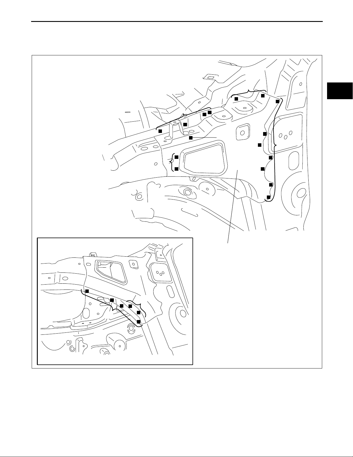
5. Drill the 9 locations indicated by (F), 6 locations on the driver’s side indicated by (G), 5 locations on the
passenger’s side.
6. When the front side frame component is being removed, the hinge pillar (inner) may interfere with the apron
reinforcement (upper) and make removal difficult, drill the 2 locations indicated by (H), 3 locations indicated by
(I), and then open the front pillar (outer) outward.
7. Drill the 3 locations indicated by (J), and remove the front side frame component.
(F)6
DRIVER,S SIDE: 6
(G)
PASSENGER,S SIDE: 5
(F)3
COWL PANEL
(H)2
(I)2
APRON REINFORCEMENT (UPPER)
SUSPENSION HOUSING (UPPER)
(I)1
FRONT PILLAR (OUTER)
End Of Sie
09–80B–18
(J)3
B3E0980B063
Page 40

BODY STRUCTURE [PANEL REPLACEMENT]
FRONT SIDE FRAME COMPONENT INSTALLATION
C3U098053300B02
1. When installing new parts, measure and adjust the body as necessary to conform with standard dimensions.
2. Drill holes for plug welds before installing new parts.
3. Weld the 3 locations indicated by (A) and temporarily install the front side frame component.
4. After temporarily installing new parts, make sure the related parts fit properly.
5. Weld the remaining weld locations and install the front side frame component.
(A)3
09–80B
COWL PANEL
2
2
APRON REINFORCEMENT (UPPER)
1
FRONT PILLAR (OUTER)
SUSPENSION HOUSING (UPPER)
6
DRIVER,S SIDE: 6
PASSENGER,S SIDE: 5
3
B3E0980B064
09–80B–19
Page 41

BODY STRUCTURE [PANEL REPLACEMENT]
3
7
10
5
11
3
DRIVER,S SIDE: 4
PASSENGER,S SIDE
6
6
14
: 3
09–80B–20
2
3
1
B3E0980B065
Page 42

BODY STRUCTURE [PANEL REPLACEMENT]
4
4
09–80B
SIDE MEMBER DECK
4
5
FRONT SIDE FRAME
9
End Of Sie
B3E0980B066
09–80B–21
Page 43

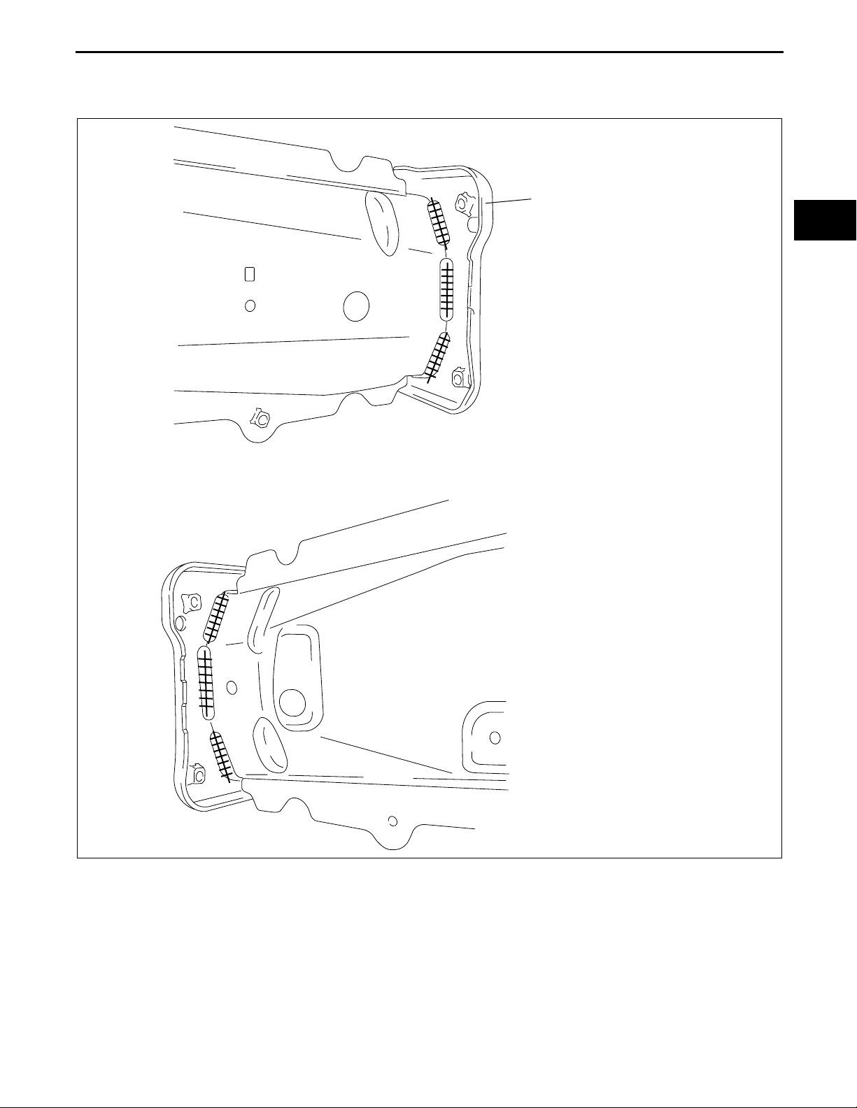
BODY STRUCTURE [PANEL REPLACEMENT]
FRONT SIDE FRAME (PARTIAL CUTTING) REMOVAL
1. Rough cut and remove the damaged part of the front side frame.
CUT-AND-JOIN LOCATION FOR
ROUGH CUT LOCATION
FOR OUTER
5
6
40mm
{1.57 in}
APRON OUTER
130mm {5.12 in}
C3U098053300B03
FRONT SIDE FRAME
CUT-AND-JOIN LOCATION FOR
INNER
ROUGH CUT LOCATION
FOR INNER
310mm {12.20 in}
40mm
{1.57 in}
End Of Sie
FRONT SIDE FRAME (PARTIAL CUTTING) INSTALLATION
Caution
•••• The cut-and-joint area indicates the maximum size range of the installation position.
B3E0980B067
C3U098053300B04
1. Make a reinforcement panel using the material of the front side frame.
2. To cut-and-join the new and existing parts, cut at the locations for the new part indicated in the figure below and
bevel the locations where the new and existing parts are joined.
3. When installing the new parts, trial-fit new and existing parts, and then measure and adjust the body to conform
with standard dimensions.
09–80B–22
Page 44

BODY STRUCTURE [PANEL REPLACEMENT]
4. To install the inner, trial-fit the new and existing parts, weld the existing parts and the reinforcement, and then
butt weld the new and existing parts.
5. Because the outer cannot be welded to the existing parts from the inside of the frame, drill 2 plug weld holes at
the locations indicated by (A) on the existing parts. Install the reinforcement and the existing parts by plug
welding from the outside of the frame, then butt weld the new and existing parts.
6. Grind the area where the inner and outer are butt welded with a disk grinder to finish the surface.
30mm {1.18 in}
65mm {2.56 in}
REINFORCEMENT
OUTER : t=1.6mm
{0.06 in}
INNER : t=1.6mm
{0.06 in}
L=10mm {0.39 in} x 6
REINFORCEMENT
09–80B
L=10mm {0.39 in} x 2
NEW FRONT SIDE FRAME (INNER)
FRONT SIDE FRAME (INNER)
310mm {12.20 in}
CUT-AND-JOIN LOCATION FOR
INNER
B3E0980B068
09–80B–23
Page 45

REINFORCEMENT
CUT-AND-JOIN LOCATION
FOR OUTER
BODY STRUCTURE [PANEL REPLACEMENT]
L=10mm {0.39 in} x 2
NEW FRONT SIDE FRAME (OUTER)
End Of Sie
5
(A)2
130mm {5.12 in}
6
FRONT SIDE FRAME (OUTER)
B3E0980B069
09–80B–24
Page 46

BODY STRUCTURE [PANEL REPLACEMENT]
TORQUE BOX REMOVAL
1. Remove the torque box.
C3U098053381B01
3
3
6
4
09–80B
End Of Sie
2
7
TORQUE BOX
B3E0980B070
09–80B–25
Page 47

BODY STRUCTURE [PANEL REPLACEMENT]
TORQUE BOX INSTALLATION
C3U098053381B02
1. When installing new parts, measure and adjust the body as necessary to conform with standard dimensions.
2. Drill holes for plug welds before installing new parts.
3. After temporarily installing new parts, make sure the related parts fit properly.
3
3
6
4
End Of Sie
2
7
TORQUE BOX
B3E0980B071
09–80B–26
Page 48

BODY STRUCTURE [PANEL REPLACEMENT]
FRONT FRAME (REAR) REMOVAL
1. Remove the front frame (rear).
18
C3U098053390B01
1
FRONT FRAME (REAR)
6
1
10
09–80B
End Of Sie
2
B3E0980B072
09–80B–27
Page 49

BODY STRUCTURE [PANEL REPLACEMENT]
FRONT FRAME (REAR) INSTALLATION
C3U098053390B02
1. When installing new parts, measure and adjust the body as necessary to conform with standard dimensions.
2. Drill holes for plug welds before installing new parts.
3. After temporarily installing new parts, make sure the related parts fit properly.
1
FRONT FRAME (REAR)
6
18
1
10
2
B3E0980B073
End Of Sie
FRONT PILLAR REMOVAL
1. Rough cut area (A) and drill the 69 locations indicated by (B).
Caution
•••• Avoid cutting with a blowtorch or similar tools as the insulator (shaded area) is flammable.
2. When the front pillar (outer) is being removed, the cowl panel may interfere with the front pillar (outer) and
make removal difficult. Therefore, drill the 2 locations indicated by (C) and then open the cowl panel outward.
3. Remove the front pillar (outer).
C3U098074090B01
09–80B–28
Page 50

COWL PANEL
BODY STRUCTURE [PANEL REPLACEMENT]
09–80B
(B)11
A-A B-B
60mm
{2.36 in}
(B)1
(C)2
(B)2
(B)1
(B)3
(B)8
(B)2
550mm {21.65 in}
(B)3
(B)4
(B)23
INSULATOR
B
A
A
(A) ROUGH CUT
LOCATION FOR
OUTER
FRONT PILLAR (OUTER)
40mm
{1.57 in}
50mm
{1.97 in}
CUT-AND-JOIN
LOCATION FOR
OUTER
(B)11
B
(A) ROUGH CUT
LOCATION FOR
OUTER
CUT-AND-JOIN
LOCATION FOR
OUTER
B3E0980B074
09–80B–29
Page 51

BODY STRUCTURE [PANEL REPLACEMENT]
4. Rough cut area (D) and drill the 10 locations indicated by (E).
5. Drill the 6 locations indicated by (F) from the interior.
6. Remove the front pillar reinforcement.
7. Rough cut area (G) and remove the side sill reinforcement.
50mm
{1.97 in}
(E)1
(E)1
FRONT PILLAR
REINFORCEMENT
60mm
{2.36 in}
CUT-AND-JOIN LOCATION
FOR REINFORCEMENT
(D) ROUGH CUT LOCATION
FOR REINFORCEMENT
(F)3
(E)2
(E)5
(G) ROUGH CUT LOCATION FOR
SIDE SILL REINFORCEMENT
CUT-AND-JOIN LOCATION FOR
SIDE SILL REINFORCEMENT
50mm
{1.97 in}
140mm
{5.51 in}
(F)3
(E)1
SIDE SILL REINFORCEMENT
09–80B–30
SIDE SILL REINFORCEMENT (UPPER)
SIDE SILL GUSSET
B3E0980B075
Page 52

BODY STRUCTURE [PANEL REPLACEMENT]
8. Rough cut area (H), drill the 9 locations indicated by (I), and then remove the front pillar (inner).
CUT-AND-JOIN LOCATION
FOR INNER
(H)ROUGH CUT LOCATION
FOR INNER
110mm
{4.33 in}
65mm
{2.56 in}
(I)7
FRONT PILLAR (INNER)
(I)2
09–80B
End Of Sie
B3E0980B076
09–80B–31
Page 53

BODY STRUCTURE [PANEL REPLACEMENT]
FRONT PILLAR INSTALLATION
C3U098074090B02
1. When joining and cutting the new and existing parts, trial fit the new part in position, and then measure and
adjust the body as necessary to conform with standard dimensions.
2. Drill holes for plug welds before installing new parts.
Note
• In areas where the outer, reinforcement, inner, and other parts are in 3-4 layers, drill holes for plug welds
in all but the innermost panel.
3. After temporarily installing new parts, make sure the related parts fit properly.
CUT-AND-JOIN LOCATION
FOR INNER
110mm
{4.33 in}
FRONT PILLAR (INNER)
2
7
B3E0980B077
09–80B–32
Page 54

BODY STRUCTURE [PANEL REPLACEMENT]
CUT-AND-JOIN LOCATION FOR
SIDE SILL REINFORCEMENT
140mm
{5.51 in}
SIDE SILL REINFORCEMENT (UPPER)
09–80B
SIDE SILL GUSSET
SIDE SILL REINFORCEMENT
60mm
{2.36 in}
CUT-AND-JOIN LOCATION
1
1
FRONT PILLAR
REINFORCEMENT
FOR REINFORCEMENT
3
3
1
2
5
B3E0980B078
09–80B–33
Page 55

COWL PANEL
BODY STRUCTURE [PANEL REPLACEMENT]
11
1
2
610mm
{24.01 in}
CUT-AND-JOIN LOCATION
FOR OUTER
1
2
3
8
3
23
2
4
FRONT PILLAR (OUTER)
50mm
{1.97 in}
End Of Sie
09–80B–34
11
CUT-AND-JOIN LOCATION
FOR OUTER
B3E0980B079
Page 56

BODY STRUCTURE [PANEL REPLACEMENT]
CENTER PILLAR REMOVAL
C3U098070350B01
1. Rough cut area (A), drill the 59 locations indicated by (B), and then remove the center pillar (outer).
Caution
•••• Avoid cutting with a blowtorch or similar tools as the insulator (shaded area) is flammable.
2. Rough cut area (C), drill the 18 locations indicated by (D), and then remove the center pillar reinforcement.
3. Rough cut area (E), drill the 4 locations indicated by (F), and then remove the side sill reinforcement.
4. Drill the 19 locations indicated by (G) and remove the center pillar (inner).
INSULATOR
80mm {3.15 in}
30mm {1.18 in}
5HB
A-A
CUT-AND-JOIN
LOCATION FOR
OUTER
(A) ROUGH
CUT LOCATION
FOR OUTER
80mm {3.15 in}
30mm {1.18 in}
CUT-AND-JOIN LOCATION
FOR OUTER
(A) ROUGH CUT LOCATION
A
A
FOR OUTER
09–80B
B-B
30mm
C-C
{1.18 in}
B
B
CUT-AND-JOIN LOCATION
FOR OUTER
CENTER PILLAR (OUTER)
INSULATOR
45mm
{1.77 in}
(A) ROUGH CUT LOCATION
FOR OUTER
(B)2
(B)20
(B)2
(B)18
(A) ROUGH CUT LOCATION
FOR OUTER
C
C
(B)17
45mm
{1.77 in}
95mm
{3.74 in}
CUT-AND-JOIN LOCATION
FOR OUTER
B3E0980B080
09–80B–35
Page 57

BODY STRUCTURE [PANEL REPLACEMENT]
(D)2
(D)1
15mm {0.59 in}
30mm {1.18 in}
(D)1
(D)10
CUT-AND-JOIN LOCATION
FOR REINFORCEMENT
(C) ROUGH CUT LOCATION
FOR REINFORCEMENT
(D)1
CENTER PILLAR REINFORCEMENT
(D)1
(D)2
(E) ROUGH CUT LOCATION
FOR SIDE SILL
REINFORCEMENT
CUT-AND-JOIN LOCATION
FOR SIDE SILL
REINFORCEMENT
80mm
{3.15 in}
40mm
{1.57 in}
End Of Sie
(F)4
SIDE SILL
REINFORCEMENT
(E) ROUGH CUT LOCATION
FOR SIDE SILL
REINFORCEMENT
CUT-AND-JOIN LOCATION
FOR SIDE SILL
REINFORCEMENT
40mm
{1.57 in}
25mm
{0.98 in}
(G)8
CENTER PILLAR (INNER)
(G)11
B3E0980B081
09–80B–36
Page 58

BODY STRUCTURE [PANEL REPLACEMENT]
CENTER PILLAR INSTALLATION
1. When joining and cutting the new and existing parts, trial fit the new part in position, and then measure and
adjust the body as necessary to conform with standard dimensions.
2. Drill holes for plug welds before installing new parts.
Note
• In areas where the outer, reinforcement, inner, and other parts are in 3-4 layers, drill holes for plug welds
in all but the innermost panel.
3. Install in the following order: inner, reinforcement, and outer.
4. Weld the 30 locations indicated by (A) and install the center pillar reinforcement (inner) to the center pillar
reinforcement.
5. After temporarily installing new parts, make sure the related parts fit properly.
C3U098070350B02
09–80B
09–80B–37
Page 59

BODY STRUCTURE [PANEL REPLACEMENT]
8
CENTER PILLAR (INNER)
CUT-AND-JOIN LOCATION
FOR SIDE SILL
REINFORCEMENT
4
CUT-AND-JOIN LOCATION
FOR SIDE SILL
REINFORCEMENT
80mm
{3.15 in}
7
CENTER PILLAR
REINFORCEMENT
SIDE SILL
REINFORCEMENT
15mm
{0.59 in}
1
(A)3
(A)11
25mm
{0.98 in}
CUT-AND-JOIN LOCATION
FOR REINFORCEMENT
1
(A)13
CENTER PILLAR
REINFORCEMENT (INNER)
09–80B–38
1
2
10
(A)3
1
2
B3E0980B082
Page 60

BODY STRUCTURE [PANEL REPLACEMENT]
80mm {3.15 in}
CUT-AND-JOIN LOCATION
FOR OUTER
2
09–80B
CUT-AND-JOIN LOCATION
FOR OUTER
End Of Sie
CENTER PILLAR (OUTER)
30mm {1.18 in}
20
17
2
95mm {3.74 in}
18
CUT-AND-JOIN LOCATION
FOR OUTER
B3E0980B083
09–80B–39
Page 61

BODY STRUCTURE [PANEL REPLACEMENT]
REAR FENDER PANEL REMOVAL
C3U098074100B01
4SD
Caution
•••• Avoid cutting with a blowtorch or similar tools as the insulator (shaded area) is flammable.
1. The rear fender panel and the rear pillar (inner) are joined with glue at the wheel arch line. Use a chisel or
similar tool to separate the rear fender panel from the rear pillar (inner), then remove the rear fender panel.
CUT-AND-JOIN
A-A
B-B
LOCATION
50mm
{1.97 in}
A
A
ROUGH CUT
LOCATION
90mm
{3.53 in}
7
5
REAR FENDER PANEL
170mm
{6.69 in}
CUT-AND-JOIN
LOCATION
50mm
{1.97 in}
B
8
B
ROUGH CUT
LOCATION
16
7
INSULATOR
2
7
7
09–80B–40
B3E0980B084
Page 62

BODY STRUCTURE [PANEL REPLACEMENT]
5HB
Caution
•••• Avoid cutting with a blowtorch or similar tools as the insulator (shaded area) is flammable.
1. The rear fender panel and the rear pillar (inner) are joined with glue at the wheel arch line. Use a chisel or
similar tool to separate the rear fender panel from the rear pillar (inner), then remove the rear fender panel.
6
A-A B-B C-C
09–80B
CUT-AND-JOIN
LOCATION
170mm
{6.69 in}
ROUGH CUT
LOCATION
50mm
{1.97 in}
C
100mm
{3.94 in}
40mm
{1.57 in}
17
B
B
A
A
20mm
{0.79 in}
40mm
{1.57 in}
7
INSULATOR
7
CUT-AND-JOIN LOCATION
ROUGH CUT LOCATION
REAR FENDER PANEL
7
CUT-AND-JOIN
LOCATION
End Of Sie
C
ROUGH CUT
LOCATION
9
3
7
B3E0980B085
09–80B–41
Page 63

BODY STRUCTURE [PANEL REPLACEMENT]
REAR FENDER PANEL INSTALLATION
C3U098074100B02
4SD
1. When joining and cutting the new and existing parts, trial fit the new part in position, and then measure and
adjust the body as necessary to conform with standard dimensions.
2. Drill holes for plug welds before installing new parts.
3. Before installing new parts, apply spot weld sealer to the wheel arch line.
4. After temporarily installing new parts, make sure the related parts fit properly.
CUT-AND-JOIN LOCATION
140mm
{5.51 in}
2
4
5
7
170mm
{6.69 in}
CUT-AND-JOIN
LOCATION
REAR FENDER
16
7
8
2
7
7
PANEL
09–80B–42
B3E0980B086
Page 64

BODY STRUCTURE [PANEL REPLACEMENT]
5HB
1. When joining and cutting the new and existing parts, trial fit the new part in position, and then measure and
adjust the body as necessary to conform with standard dimensions.
2. Drill holes for plug welds before installing new parts.
3. Before installing new parts, apply spot weld sealer to the wheel arch line.
4. After temporarily installing new parts, make sure the related parts fit properly.
6
09–80B
CUT-AND-JOIN LOCATION
100mm
{3.94 in}
2
4
17
170mm
{6.69 in}
20mm
{0.79 in}
7
7
CUT-AND-JOIN LOCATION
REAR FENDER PANEL
7
End Of Sie
CUT-AND-JOIN
LOCATION
7
9
3
B3E0980B087
09–80B–43
Page 65

BODY STRUCTURE [PANEL REPLACEMENT]
REAR FENDER LOWER PANEL REMOVAL
4SD
1. Remove the rear fender lower panel.
4
C3U098074100B03
REAR FENDER LOWER PANEL
6
5
B3E0980B088
09–80B–44
Page 66

BODY STRUCTURE [PANEL REPLACEMENT]
5HB
1. Drill the 16 locations indicated by (A).
2. Drill the 2 locations indicated by (B) and remove the rear fender lower panel.
(A)1
REAR FENDER LOWER PANEL
(A)4
(A)3
(A)8
09–80B
End Of Sie
REAR END PANEL
(B)2
B3E0980B089
09–80B–45
Page 67

BODY STRUCTURE [PANEL REPLACEMENT]
REAR FENDER LOWER PANEL INSTALLATION
C3U098074100B04
4SD
1. When installing new parts, measure and adjust the body as necessary to conform with standard dimensions.
2. Drill holes for plug welds before installing new parts.
3. After temporarily installing new parts, make sure the related parts fit properly.
REAR FENDER LOWER PANEL
6
4
5
B3E0980B090
09–80B–46
Page 68

BODY STRUCTURE [PANEL REPLACEMENT]
5HB
1. When installing new parts, measure and adjust the body as necessary to conform with standard dimensions.
2. Drill holes for plug welds before installing new parts.
3. Weld the 2 locations indicated by (A) and install the rear fender lower panel.
4. After temporarily installing new parts, make sure the related parts fit properly.
REAR END PANEL
(A)2
09–80B
End Of Sie
1
REAR FENDER LOWER PANEL
4
3
8
B3E0980B091
09–80B–47
Page 69

BODY STRUCTURE [PANEL REPLACEMENT]
SIDE SILL PANEL REMOVAL
C3U098070270B01
1. Rough cut area (A), drill the 99 locations indicated by (B), the 2 locations (4SD) or 3 locations (5HB) indicated
by (C), and then remove the side sill (outer).
Caution
•••• Avoid cutting with a blowtorch or similar tools as the insulator (shaded area) is flammable.
2. Rough cut area (D) and drill the 3 locations indicated by (E).
3. Drill the 4 locations indicated by (F) from the interior and remove the side sill reinforcement.
CUT-AND-JOIN
LOCATION FOR
OUTER
(A)ROUGH CUT
B
LOCATION FOR
OUTER
(B)18
INSULATOR
130mm
{5.12 in}
30mm
{1.18 in}
C
C
CUT-AND-JOIN
LOCATION FOR
OUTER
(A)ROUGH CUT
LOCATION FOR
OUTER
(B)4
(C)
4SD:2
5HB:3
260mm
{10.24 in}
30mm
{1.18 in}
CUT-AND-JOIN LOCATION
FOR OUTER
(A)ROUGH CUT
AA
(B)8
INSULATOR
LOCATION FOR
OUTER
(B)24
240mm
{9.45 in}
35mm
{1.38 in}
SIDE SILL (OUTER)
B
(B)2
(B)43
50mm
{1.97 in}
30mm
{1.18 in}
End Of Sie
(F)4
A-A B-B C-C
CUT-AND-JOIN LOCATION FOR
REINFORCEMENT
(D)ROUGH CUT
LOCATION FOR
REINFORCEMENT
55mm {2.17 in}
25mm {0.98 in}
(E)1
(E)1
SIDE SILL REINFORCEMENT
CUT-AND-JOIN LOCATION
FOR REINFORCEMENT
(D)ROUGH CUT
LOCATION FOR
REINFORCEMENT
(E)1
B3U0980B092
09–80B–48
Page 70

BODY STRUCTURE [PANEL REPLACEMENT]
SIDE SILL PANEL INSTALLATION
C3U098070270B02
1. When joining and cutting the new and existing parts, trial fit the new part in position, and then measure and
adjust the body as necessary to conform with standard dimensions.
2. Drill holes for plug welds before installing new parts.
Note
• In areas where the outer, reinforcement, inner, and other parts are in 3-4 layers, drill holes for plug welds
in all but the innermost panel.
3. Weld the 7 locations indicated by (A) and temporarily install the side sill reinforcement.
4. After temporarily installing new parts, make sure the related parts fit properly.
(A)4
09–80B
50mm
{1.97 in}
260mm
{10.24 in}
CUT-AND-JOIN LOCATION
FOR REINFORCEMENT
55mm
(A)1
CUT-AND-JOIN LOCATION
FOR OUTER
8
{2.17 in}
(A)1
SIDE SILL REINFORCEMENT
240mm
{9.45 in}
2
24
CUT-AND-JOIN LOCATION
FOR REINFORCEMENT
(A)1
CUT-AND-JOIN LOCATION
FOR OUTER
130mm
{5.12 in}
18
CUT-AND-JOIN
LOCATION FOR
OUTER
4
End Of Sie
43
SIDE SILL (OUTER)
4SD:2
5HB:3
B3E0980B093
09–80B–49
Page 71

BODY STRUCTURE [PANEL REPLACEMENT]
REAR END PANEL REMOVAL
4SD
1. Remove the rear end panel.
6
7
1
3
5
REAR END PANEL
15
C3U098070750B01
6
1
3
5
7
B3E0980B094
09–80B–50
Page 72

BODY STRUCTURE [PANEL REPLACEMENT]
5HB
1. Remove the rear end panel.
2
09–80B
REAR END PANEL
End Of Sie
4
2
6
5
5
5
5
15
5
5
5
4
2
6
5
B3E0980B095
09–80B–51
Page 73

BODY STRUCTURE [PANEL REPLACEMENT]
REAR END PANEL INSTALLATION
4SD
C3U098070750B02
1. When installing new parts, measure and adjust the body as necessary to conform with standard dimensions.
2. Drill holes for plug welds before installing new parts.
3. After temporarily installing new parts, make sure the related parts fit properly.
6
7
1
3
5
REAR END PANEL
5
15
6
7
1
3
B3E0980B096
09–80B–52
Page 74

BODY STRUCTURE [PANEL REPLACEMENT]
5HB
1. When installing new parts, measure and adjust the body as necessary to conform with standard dimensions.
2. Drill holes for plug welds before installing new parts.
3. After temporarily installing new parts, make sure the related parts fit properly.
2
REAR END PANEL
4
2
6
5
5
5
5
5
4
2
6
5
09–80B
End Of Sie
5
15
5
B3E0980B097
09–80B–53
Page 75

BODY STRUCTURE [PANEL REPLACEMENT]
REAR FENDER RAIN RAIL AND CORNER PLATE REMOVAL
4SD
1. Remove the rear fender rain rail and corner plate.
Note
• When removing the rear fender rain rail and the corner plate separately, drill the 3 locations indicated by
(A).
2
3
3
2
C3U098070440B01
REAR FENDER RAIN RAIL
1
CORNER PLATE
(A)3
B3E0980B098
09–80B–54
Page 76

BODY STRUCTURE [PANEL REPLACEMENT]
5HB
1. Remove the rear fender rain rail and corner plate.
Note
• When removing the rear fender rain rail and the corner plate separately, drill the 8 locations indicated by
(A).
CUT-AND-JOIN LOCATION
110mm {4.33 in}
40mm {1.57 in}
6
(A)4
REAR CUT LOCATION
REAR FENDER RAIN RAIL
CORNER PLATE
09–80B
End Of Sie
(A)4
1
B3E0980B099
09–80B–55
Page 77

BODY STRUCTURE [PANEL REPLACEMENT]
REAR FENDER RAIN RAIL AND CORNER PLATE INSTALLATION
C3U098070440B02
4SD
1. When installing new parts, measure and adjust the body as necessary to conform with standard dimensions.
2. Drill holes for plug welds before installing new parts.
3. After temporarily installing new parts, make sure the related parts fit properly.
Note
• When replacing the rear fender rain rail and corner plate separately, weld the 3 locations indicated by (A).
2
3
3
2
REAR FENDER RAIN RAIL
1
CORNER PLATE
(A)3
B3E0980B100
09–80B–56
Page 78

BODY STRUCTURE [PANEL REPLACEMENT]
5HB
1. When installing new parts, measure and adjust the body as necessary to conform with standard dimensions.
2. Drill holes for plug welds before installing new parts.
3. After temporarily installing new parts, make sure the related parts fit properly.
Note
• When replacing the rear fender rain rail and corner plate separately, weld the 8 locations indicated by (A).
CUT-AND-JOIN LOCATION
110mm {4.33 in}
REAR FENDER RAIN RAIL
6
CORNER PLATE
09–80B
End Of Sie
(A)4
(A)4
1
B3E0980B101
09–80B–57
Page 79

BODY STRUCTURE [PANEL REPLACEMENT]
REAR FLOOR PAN REMOVAL
1. Rough cut area (A).
Caution
•••• When rough cutting area (A), cut 20mm {0.79 in} away from the flange (towards rear) at the rear of
the lower anchor.
2. Remove the rear floor pan.
(A) ROUGH CUT LOCATION
FOR REAR FLOOR PAN
REAR FLOOR PAN
LOWER ANCHOR
20mm
{0.79 in}
CROSSMEMBER No.4
A-A
(A) ROUGH CUT LOCATION
FOR REAR FLOOR PAN
A
A
C3U098053750B01
4
6
8
5
3
13
8
REAR FLOOR PAN
4
6
8
13
5
3
B3E0980B102
09–80B–58
Page 80

BODY STRUCTURE [PANEL REPLACEMENT]
2
3
09–80B
End Of Sie
B3E0980B103
09–80B–59
Page 81

BODY STRUCTURE [PANEL REPLACEMENT]
REAR FLOOR PAN INSTALLATION
C3U098053750B02
1. To prepare for installation, cut area (A) on the new rear floor pan, drill the 20 locations indicated by (B) and then
remove the lower anchor.
Caution
•••• When rough cutting area (A), cut 30 mm {1.18 in} away from the flange (towards front) at the rear of
the lower anchor.
(A) ROUGH CUT LOCATION
FOR REAR FLOOR PAN
LOWER ANCHOR
30mm
{1.18 in}
A-A
REAR FLOOR PAN
NEW REAR FLOOR PAN
(A) ROUGH CUT LOCATION
FOR REAR FLOOR PAN
CROSSMEMBER No.4
A
(B)5 (B)5 (B)5
A
(B)5
B3E0980B104
2. Drill the 11 locations indicated by (A).
3. Separate the lower anchor where joined using a chisel or similar tool and bend upwards to facilitate installation.
(C)3
EXISTING REAR FLOOR PAN
(C)3 (C)2(C)3
LOWER ANCHOR
09–80B–60
B3E0980B105
Page 82

BODY STRUCTURE [PANEL REPLACEMENT]
4. Apply spot sealer to the areas where both the overlapping ends of the new and existing parts will be welded.
Adhere the sections to be welded, and plug weld in 18 locations indicated by (D). Fillet weld along the seams of
the lower anchor, and new and existing parts at the locations indicated by (E).
Note
• Create a flange with flanging seal where new and existing parts are joined.
5. Weld the remaining weld locations and install the rear floor pan.
(E) FILLET WELDIMG
LOWER ANCHOR
EXISTING PARTS
NEW PARTS
CROSSMEMBER No.4
B-B
8
5
09–80B
B
(D)3
(D)2
4
6
13
(D)3 (D)3 (D)2
8
(D)3
B
4
6
8
13
5
(D)2
End Of Sie
3
REAR FLOOR PAN
2
3
3
B3E0980B106
09–80B–61
Page 83

BODY STRUCTURE [PANEL REPLACEMENT]
REAR SIDE FRAME (PARTIAL CUTTING) REMOVAL
1. Rough cut and remove the damaged part of the rear side frame.
50mm
{1.97 in}
C3U098053810B01
200mm {7.87 in}
CUT-AND-JOIN LOCATION
End Of Sie
ROUGH CUT LOCATION
B3E0980B107
09–80B–62
Page 84

BODY STRUCTURE [PANEL REPLACEMENT]
REAR SIDE FRAME (PARTIAL CUTTING) INSTALLATION
C3U098053810B02
1. Cut the new and existing parts at the cut-and-join location, and bevel the parts.
2. To cut-and-join the new part, cut at the locations indicated in the figure below and bevel the cut-and-join
locations of the new parts.
3. When installing the new parts, trial-fit new and existing parts, and then measure and adjust the body to conform
with standard dimensions.
4. After temporarily installing new parts, make sure the related parts fit properly.
Caution
•••• The cut-and-join area indicates the maximum size range of the installation position.
200mm {7.87 in}
09–80B
End Of Sie
CUT-AND-JOIN LOCATION
B3E0980B108
09–80B–63
Page 85

BODY STRUCTURE [PANEL REPLACEMENT]
ROOF PANEL REMOVAL
4SD
1. Remove the roof panel.
17
C3U098070600B01
WITH SUNROOF:19
WITHOUT SUNROOF:20
13
WITH SUNROOF:19
WITHOUT SUNROOF:20
B3E0980B109
09–80B–64
Page 86

5HB
1. Remove the roof panel.
BODY STRUCTURE [PANEL REPLACEMENT]
1
17
4
09–80B
3
28
15
End Of Sie
28
B3E0980B110
09–80B–65
Page 87

BODY STRUCTURE [PANEL REPLACEMENT]
ROOF PANEL INSTALLATION
C3U098070600B02
4SD
1. When installing new parts, measure and adjust the body as necessary to conform with standard dimensions.
2. Drill holes for plug welds before installing new parts.
3. After temporarily installing new parts, make sure the related parts fit properly.
WITH SUNROOF:19
WITHOUT SUNROOF:20
17
13
WITH SUNROOF:19
WITHOUT SUNROOF:20
B3E0980B111
09–80B–66
Page 88

BODY STRUCTURE [PANEL REPLACEMENT]
5HB
1. When installing new parts, measure and adjust the body as necessary to conform with standard dimensions.
2. Drill holes for plug welds before installing new parts.
3. After temporarily installing new parts, make sure the related parts fit properly.
17
28
1
4
3
15
09–80B
End Of Sie
28
B3E0980B112
09–80B–67
Page 89

BODY STRUCTURE [WATER-PROOF AND RUST PREVENTIVE]
09–80C BODY STRUCTURE [WATER-PROOF AND RUST
PREVENTIVE]
BODY SEALING . . . . . . . . . . . . . . . . . . . 09–80C–2
4SD . . . . . . . . . . . . . . . . . . . . . . . . . . . 09–80C–2
5HB . . . . . . . . . . . . . . . . . . . . . . . . . . . 09–80C–5
UNDER COATING. . . . . . . . . . . . . . . . . . 09–80C–8
CHIPPING-RESISTANT COATING. . . . . 09–80C–9
End of Toc
With Side Step Molding . . . . . . . . . . . . . 09–80C–9
Without Side Step Molding . . . . . . . . . . 09–80C–9
RUST PREVENTIVE TREATMENT . . . . .09–80C–10
4SD . . . . . . . . . . . . . . . . . . . . . . . . . . . . 09–80C–10
5HB . . . . . . . . . . . . . . . . . . . . . . . . . . . . 09–80C–11
09–80C
09–80C–1
Page 90

BODY STRUCTURE [WATER-PROOF AND RUST PREVENTIVE]
BODY SEALING
Sealant is applied to the parts where the panels meet and to the hemmed parts of the door panel and hood panel
to provide water proofing and rust proofing.
4SD
C3U098007000B02
09–80C–2
B3U0980B032
Page 91

BODY STRUCTURE [WATER-PROOF AND RUST PREVENTIVE]
09–80C
B3U0980B033
09–80C–3
Page 92

BODY STRUCTURE [WATER-PROOF AND RUST PREVENTIVE]
HOOD
DOOR
TRUNK LID
09–80C–4
B3U0980B034
Page 93

5HB
BODY STRUCTURE [WATER-PROOF AND RUST PREVENTIVE]
09–80C
B3U0980B035
09–80C–5
Page 94

BODY STRUCTURE [WATER-PROOF AND RUST PREVENTIVE]
09–80C–6
B3U0980B033
Page 95

HOOD
DOOR
BODY STRUCTURE [WATER-PROOF AND RUST PREVENTIVE]
09–80C
End Of Sie
LIFTGATE
B3U0980B037
09–80C–7
Page 96

BODY STRUCTURE [WATER-PROOF AND RUST PREVENTIVE]
UNDER COATING
The shaded areas indicated under body locations that are undercoated to prevent noise and rusting.
C3U098007000B03
End Of Sie
B3U0980B038
09–80C–8
Page 97

BODY STRUCTURE [WATER-PROOF AND RUST PREVENTIVE]
CHIPPING-RESISTANT COATING
The coating locations are indicated by the shaded areas.
With Side Step Molding
C3U098007000B04
09–80C
A
A
OVER SPRAY ALLOWED
Without Side Step Molding
OVER SPRAY ALLOWED
URETHANE PAINT
A-A
B3E0980B039
A
A
End Of Sie
URETHANE PAINT
A-A
B3U0980B046
09–80C–9
Page 98

BODY STRUCTURE [WATER-PROOF AND RUST PREVENTIVE]
RUST PREVENTIVE TREATMENT
4SD
HOOD
DOOR
C3U098007000B05
TRUNK LID
B3U0980B040
09–80C–10
Page 99

5HB
BODY STRUCTURE [WATER-PROOF AND RUST PREVENTIVE]
HOOD
09–80C
DOOR
End Of Sie
LIFTGATE
B3U0980B045
09–80C–11
Page 100

BODY STRUCTURE [DIMENSIONS]
09–80D BODY STRUCTURE [DIMENSIONS]
UNDERBODY FLAT-PLANE
DIMENSIONS . . . . . . . . . . . . . . . . . . . . 09–80D–2
UNDERBODY STRAIGHT-LINE
DIMENSIONS . . . . . . . . . . . . . . . . . . . . 09–80D–3
FRONT BODY STRAIGHT-LINE
DIMENSIONS (1) . . . . . . . . . . . . . . . . . . 09–80D–4
FRONT BODY STRAIGHT-LINE
DIMENSIONS (2) . . . . . . . . . . . . . . . . . . 09–80D–5
4SD . . . . . . . . . . . . . . . . . . . . . . . . . . . 09–80D–5
5HB . . . . . . . . . . . . . . . . . . . . . . . . . . . 09–80D–6
FRONT BODY STRAIGHT-LINE
DIMENSIONS (3) . . . . . . . . . . . . . . . . . . 09–80D–7
4SD . . . . . . . . . . . . . . . . . . . . . . . . . . . 09–80D–7
5HB . . . . . . . . . . . . . . . . . . . . . . . . . . . 09–80D–8
End of Toc
CABIN SIDE FRAME STRAIGHT-LINE
DIMENSIONS . . . . . . . . . . . . . . . . . . . . . 09–80D–9
4SD . . . . . . . . . . . . . . . . . . . . . . . . . . . . 09–80D–9
5HB . . . . . . . . . . . . . . . . . . . . . . . . . . . . 09–80D–10
ROOM STRAIGHT-LINE
DIMENSIONS (1) . . . . . . . . . . . . . . . . . . 09–80D–11
ROOM STRAIGHT-LINE
DIMENSIONS (2) . . . . . . . . . . . . . . . . . . 09–80D–12
4SD . . . . . . . . . . . . . . . . . . . . . . . . . . . . 09–80D–12
5HB . . . . . . . . . . . . . . . . . . . . . . . . . . . . 09–80D–13
REAR BODY STRAIGHT-LINE
DIMENSIONS . . . . . . . . . . . . . . . . . . . . . 09–80D–14
4SD . . . . . . . . . . . . . . . . . . . . . . . . . . . . 09–80D–14
5HB . . . . . . . . . . . . . . . . . . . . . . . . . . . . 09–80D–15
09–80D
09–80D–1
 Loading...