

Page 1
up to October, 2008. Any changes that occur
2008 Mazda Motor Corporation
PRINTED IN U.S.A., OCTOBER 2008
Part No. 9999-95-E13B-MSP09
Page 2
Engine Workshop Manual 13B-MSP (Multi Side Port) (1773–1U–03C)
GENERAL INFORMATION
To c o f S C T
GENERAL INFORMATION . . . . 00-00
To c o f S C T
00–00 GENERAL INFORMATION
HOW TO USE THIS MANUAL . . . . . . . . . 00–00–1
Range of Topics . . . . . . . . . . . . . . . . . . 00–00–1
Service Procedure . . . . . . . . . . . . . . . . 00–00–2
Symbols . . . . . . . . . . . . . . . . . . . . . . . . 00–00–4
Advisory Messages . . . . . . . . . . . . . . . . 00–00–4
UNITS . . . . . . . . . . . . . . . . . . . . . . . . . . . . 00–00–5
Conversion to SI Units
(Système International d'Unités) . . . . . 00–00–5
Rounding Off. . . . . . . . . . . . . . . . . . . . . 00–00–5
Upper and Lower Limits . . . . . . . . . . . . 00–00–5
FUNDAMENTAL PROCEDURES. . . . . . . 00–00–6
Preparation of Tools and Measuring
Equipment. . . . . . . . . . . . . . . . . . . . . . 00–00–6
Special Service Tools . . . . . . . . . . . . . . 00–00–6
Disassembly . . . . . . . . . . . . . . . . . . . . . 00–00–6
Inspection During Removal,
Disassembly. . . . . . . . . . . . . . . . . . . . 00–00–6
Arrangement of Parts . . . . . . . . . . . . . . 00–00–7
Cleaning of Parts . . . . . . . . . . . . . . . . . 00–00–7
Reassembly . . . . . . . . . . . . . . . . . . . . . 00–00–7
Adjustment . . . . . . . . . . . . . . . . . . . . . . 00–00–8
Rubber Parts and Tubing . . . . . . . . . . . 00–00–8
Hose Clamps . . . . . . . . . . . . . . . . . . . . 00–00–8
Torque Formulas . . . . . . . . . . . . . . . . . 00–00–8
Vise . . . . . . . . . . . . . . . . . . . . . . . . . . . 00–00–9
ELECTRICAL SYSTEM. . . . . . . . . . . . . . 00–00–9
Connectors. . . . . . . . . . . . . . . . . . . . . . 00–00–9
SAE STANDARDS. . . . . . . . . . . . . . . . . . 00–00–11
ABBREVIATIONS . . . . . . . . . . . . . . . . . . 00–00–11
IDENTIFYING SPECIFICATION . . . . . . . 00–00–12
00
SECTION
00–00
End of Toc
HOW TO USE THIS MANUAL
Range of Topics
• This manual contains procedures for performing all required service operations. The procedures are divided
into the following five basic operations:
— Removal/Installation
— Disassembly/Assembly
— Replacement
— Inspection
— Adjustment
• Simple operations which can be performed easily just by looking at the vehicle (i.e., removal/installation of
parts, jacking, vehicle lifting, cleaning of parts, and visual inspection) have been omitted.
CHU000000001E01
Revised 6/2008 (Ref. No. R108/08)
00–00–1
Page 3
Engine Workshop Manual 13B-MSP (Multi Side Port) (1773–1U–03C)
GENERAL INFORMATION
Service Procedure
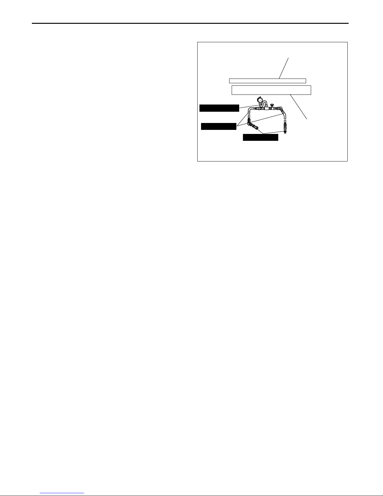
Inspection, adjustment
• Inspection and adjustment procedures are
divided into steps. Important points regarding the
location and contents of the procedures are
explained in detail and shown in the illustrations.
Fluid Pressure Inspection
1. Assemble the SSTs as shown in the figure.
49 1232 670A
SHOWS PROCEDURE ORDER
FOR SERVICE
Tightening torque
39—49 N·m {4.0—5.0 kgf·m, 29—36 ft·lbf}
49 H002 671
SHOWS TIGHTENING
TORQUE
49 H032 322
Caution
Connect the gauge set from under
the vehicle to prevent contact with
the drive belt and the cooling fan.
SPECIFICATIONS
WGIWXX0009E
00–00–2
Page 4
GENERAL INFORMATION
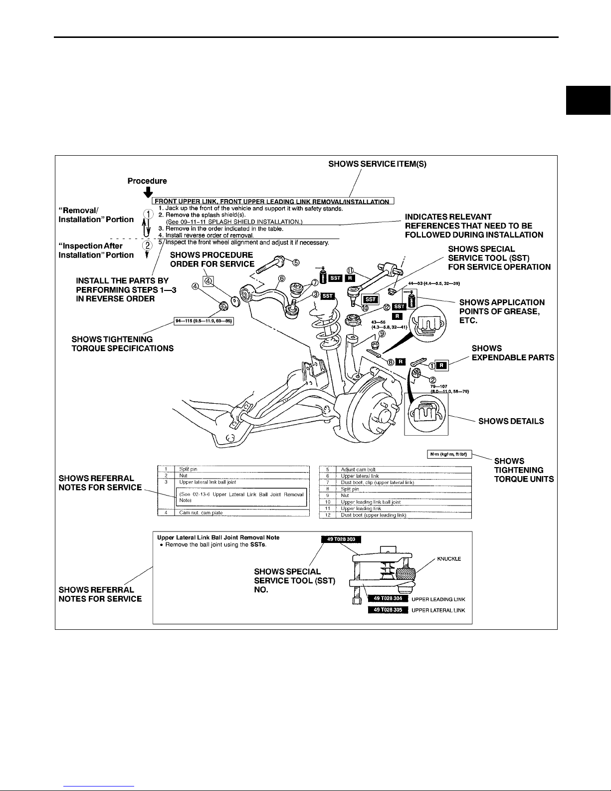
Repair procedure
1. Most repair operations begin with an overvie w illustration. It identifies the compo nent s , shows how the parts fit
together, and describes visual part inspection. However, only removal/installation procedures that need to be
performed methodically have written instructions.
2. Expendable parts, tightening torques, and symbols for oil, grease, and sealant are shown in the overview
illustration. In addition, symbols indicating parts requiring the use of special s ervi c e too ls or equivalent are also
shown.
3. Procedure steps are numb er ed and the part th at is the main poin t of that procedure is shown in the illustration
with the corresponding number. Occasionally, there are important points or additional information concerning a
procedure. Refer to this information when servicing the related par t.
00–00
YLU000WA0
00–00–3
Page 5
GENERAL INFORMATION
OIL
TF
GREASE
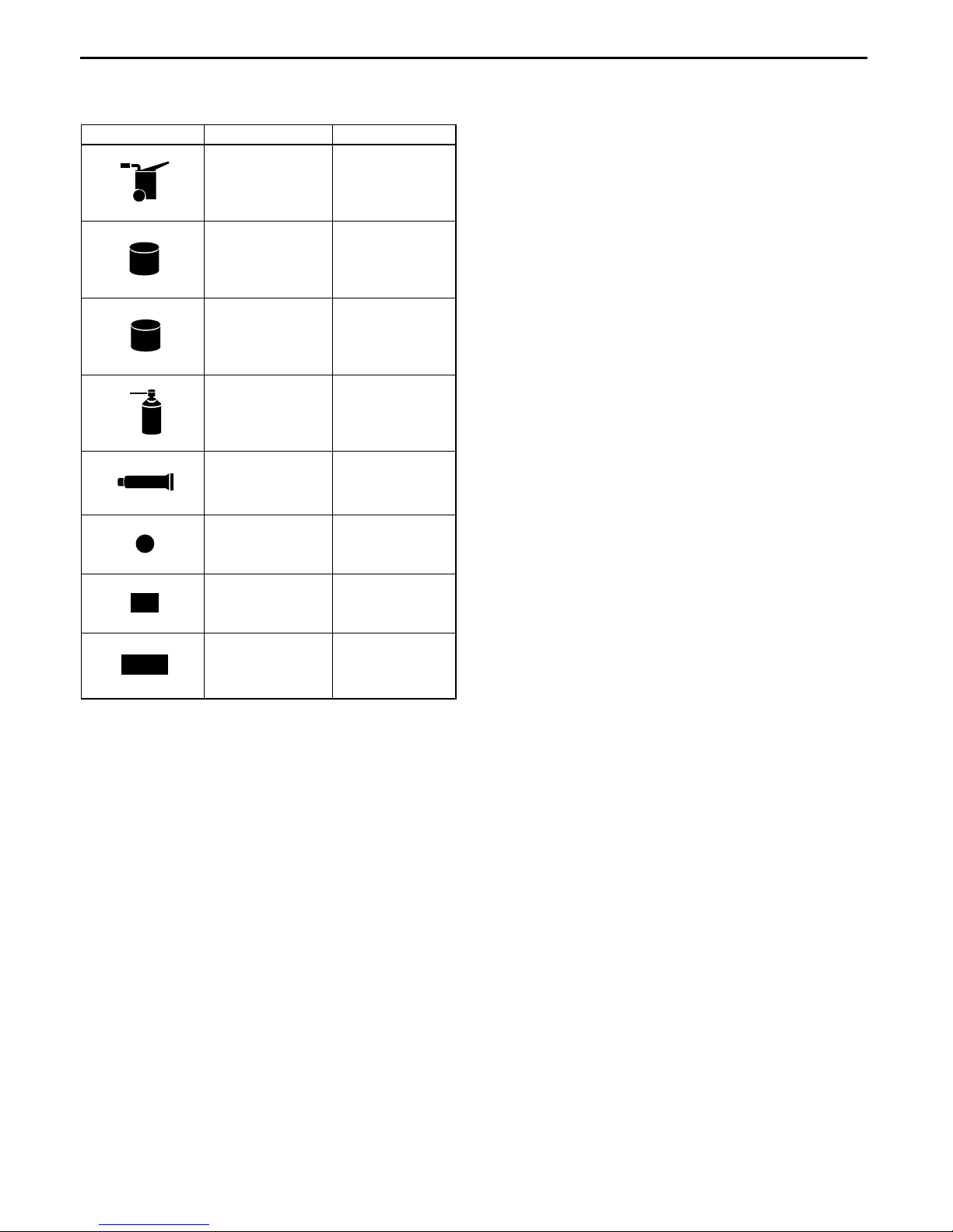
Symbols
• There are eight symbols indicating oil, grease, fluids, sealant, and the use of SST or equivalent. These symbols
show application points or use of thes e materia ls duri ng se rvic e.
Symbol Meaning Kind
OIL
BRAKE
FLUID
AATF
GREASE
SEALANT
P
R
Apply oil
Apply brake fluid
Apply automatic
transaxle/
transmission fluid
Apply grease
Apply sealant
Apply petroleum
jelly
Replace part
New appropriate
engine oil or gear
oil
New appropriate
brake fluid
New appropriate
automatic
transaxle/
transmission fluid
Appropriate
grease
Appropriate
sealant
Appropriate
petroleum jelly
O-ring, gasket,
etc.
SST
Use SST or
equivalent
Appropriate tools
Advisory Messages
• You will find several Warnings, Cautions, Notes, Specifications and Upper and Lower Limits in this
manual.
Warning
• A Warning indicates a situation in which serious injury or death could result if the warning is ignored.
Caution
• A Caution indicates a situation in which damage to the vehicle or parts could result if the caution is ignored.
Note
• A Note provides added information that will help you to complete a particular procedure.
Specification
• The values indicate the allowable range when performing inspections or adjustments.
Upper and lower limits
• The values indicate the upper and lower limits that must not be exceeded when performing inspections or
adjustments.
End Of Sie
00–00–4
Page 6
GENERAL INFORMATION
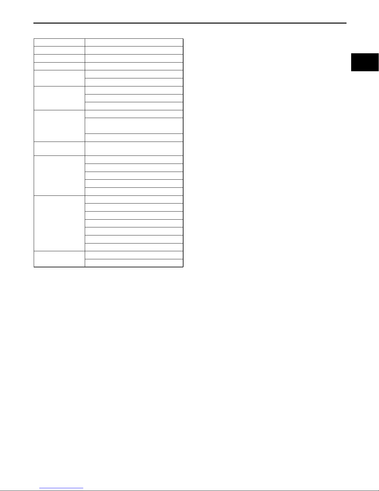
UNITS
Electric current A (ampere)
Electric power W (watt)
Electric resistance ohm
Electric voltage V (volt)
Length
Negative pressure
Positive pressure
Number of
revolutions
Torque
Volume
Weight
mm (millimeter)
in (inch)
kPa (kilo pascal)
mmHg (millimeters of mercury)
inHg (inches of mercury)
kPa (kilo pascal)
2
kgf/cm
centimeter)
psi (pounds per square inch)
rpm (revolutions per minute)
N·m (Newton meter)
kgf·m (kilogram force meter)
kgf·cm (kilogram force centimeter)
ft·lbf (foot pound force)
in·lbf (inch pound for ce)
L (liter)
US qt (U.S. quart)
Imp qt (Imperial quart)
ml (milliliter)
cc (cubic centimeter)
cu in (cubic inch)
fl oz (fluid ounce )
g (gram)
oz (ounce)
(kilogram force per square
CHU000000002E01
00–00
Conversion to SI Units (Système International d'Unités)
• All numerical values in this manual are based on SI units. Numbers shown in conventional units are converted
from these values.
Rounding Off
• Converted values are rounded off to the same number of places as the SI unit value. For example, if the SI uni t
value is 17.2 and the value after conversion is 37.84, the converted value will be rounded off to 37.8.
Upper and Lower Limits
• When the data indicates upper and lower limits, the converted values are rounded down if the SI unit value is
an upper limit and rounded up if the SI unit value is a lower limit. Therefore, converted values for the same SI
unit value ma y differ afte r conversion. For example, co ns ide r 2.7 kg f/c m
210—260 kPa {2.1—2.7 kgf/cm
270—310 kPa {2.7—3.2 kgf/cm
• The actual converted values for 2.7 kgf/cm
2
, 30—38 psi}
2
, 39—45 psi}
2
are 264 kPa and 38.4 psi. In the first specification, 2.7 is used as
2
in the following specifications:
an upper limit, so the conver ted values are rounded down to 260 and 38. In the second specification, 2.7 is
used as a lower limit, so the converted values are rounded up to 270 and 39.
End Of Sie
00–00–5
Page 7

GENERAL INFORMATION
FUNDAMENTAL PROCEDURES
Preparation of Tools and Measurin g Equipment
• Be sure that all neces sa ry tools and measuring
equipment are available before starting any work.
Special Service Tools
• Use special service tools or equivalent when they
are required.
CHU000000004E01
CHU0014W003
49 SE01 310
Disassembly
• If the disassembly procedure is complex,
requiring many parts to be disassembled, all parts
should be marked in a place that will not affect
their performance or exter nal appearance and
identified so that reassembly can be performed
easily and efficiently .
Inspection During Removal, Disassembly
• When removed, each part should be carefully
inspected for malfunction, deformation, damage
and other problems.
WGIWXX0024E
WGIWXX0027E
00–00–6
WGIWXX0028E
Page 8
GENERAL INFORMATION
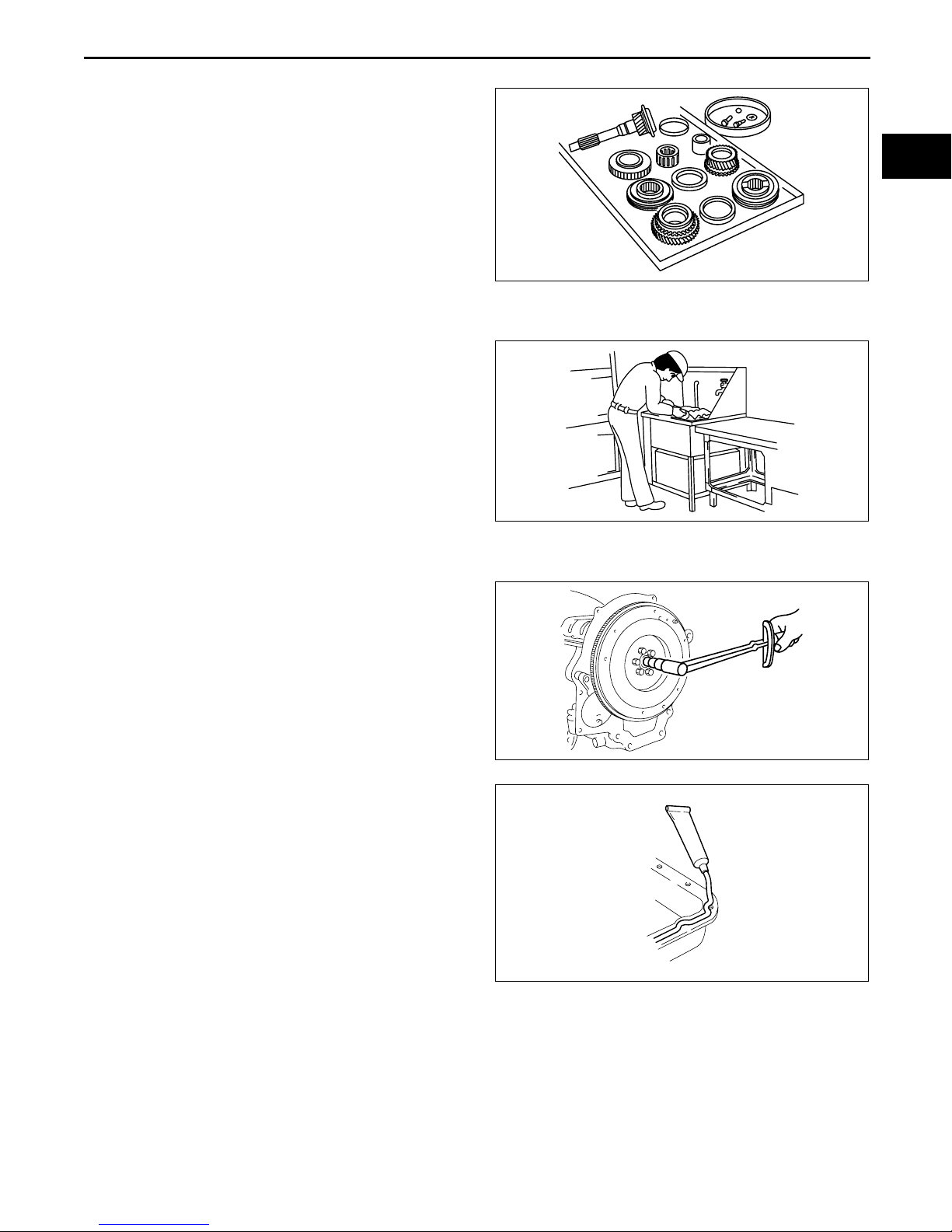
Arrangement of Parts
• All disassembled parts should be carefully
arranged for reassembl y.
• Be sure to separate or otherwise identify the parts
to be replaced from those tha t will be re used.
Cleaning of Parts
• All parts to be reused should be carefully and
thoroughly cleaned in the appropriate method.
Warning
•
• Using compressed air can cause dirt and
••
other particles to fly out causing injury to
the eyes. Wear protective eye wear
whenever using compressed air.
00–00
WGIWXX0029E
Reassembly
• Standard values, such as torque s and certain
adjustments, must be strictly observed in the
reassembly of all parts.
• If removed, the following parts should be replaced
with new ones:
— Oil seals
— Gaskets
— O-rings
— Lock washers
— Cotter pins
— Nylon nuts
• Depending on location:
— Sealant and gaskets , or both, sh oul d be
applied to specified locations. When sealant
is applied, parts should be installed before
sealant hardens to prevent leakage.
— Oil should be applied to the movin g
components of parts.
— Specified oil or grease shou ld be appl ie d a t
the prescribed locations (such as oil seals)
before reassembly.
WGIWXX0030E
WGIWXX0031E
CHU0014W006
00–00–7
Page 9
GENERAL INFORMATION
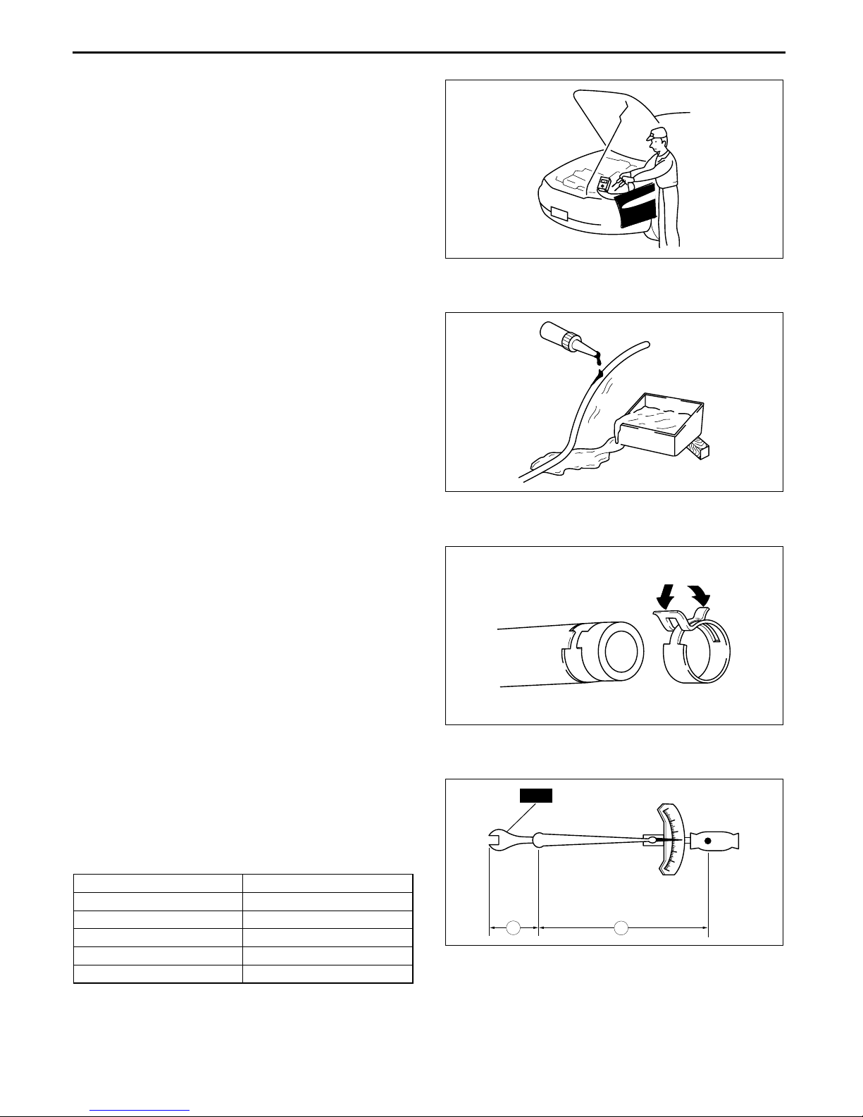
Adjustment
• Use suitable gauges and testers when making
adjustments.
Rubber Parts and Tubing
• Prevent gasoline or oil from getting on rubber
parts or tubing.
CHU0014W005
Hose Clamps
• When reinstalling, pos i tion the hos e cl amp in the
original location on the hose and squeeze the
clamp lightly with large pliers to ensure a good fit.
Torque Formulas
• When using a torque wrench-SST or equivalent
combination, the writt en torque must be
recalculated due to the ext ra le ngth that the SST
or equivalent adds to the torque wrench.
Recalculate the torque by using the following
formulas. Choose the formula that applies to you.
Torque Unit Formula
N·mN·m × [L/(L+A)]
kgf·mkgf·m × [L/(L+A)]
kgf·cm kgf·cm × [L/(L+A)]
ft·lbf ft·lbf × [L/(L+A)]
in·lbf in·lbf × [L/(L+A)]
WGIWXX0034E
WGIWXX0035E
SST
A
L
3
2
1
0
1
2
3
WGIWXX0036E
A : The length of the SST past the torque wrench drive.
L : The length of the torque wrench.
00–00–8
Page 10
GENERAL INFORMATION
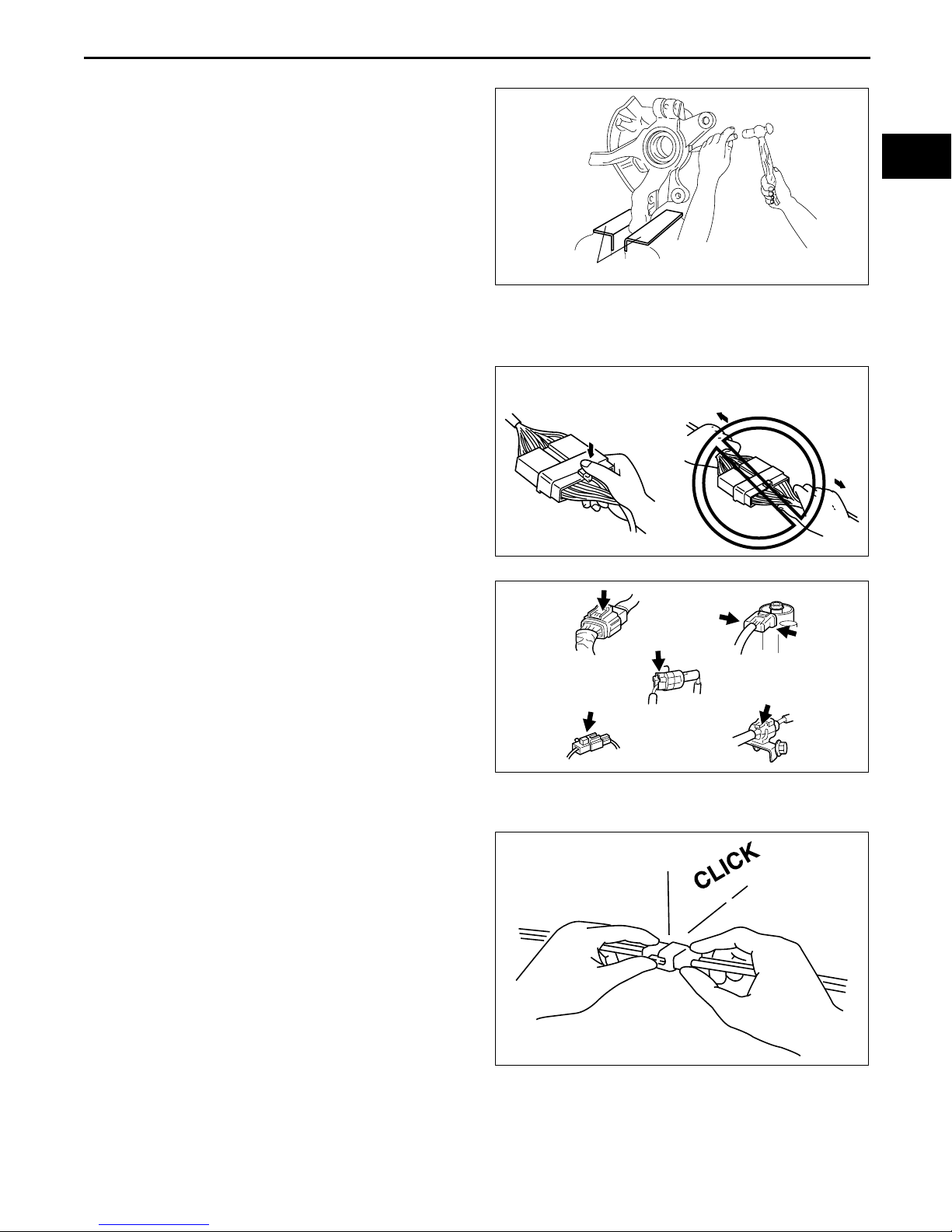
Vise
• When using a vise, put protective plates in the
jaws of the vise to prevent damage to parts.
End Of Sie
ELECTRICAL SYSTEM
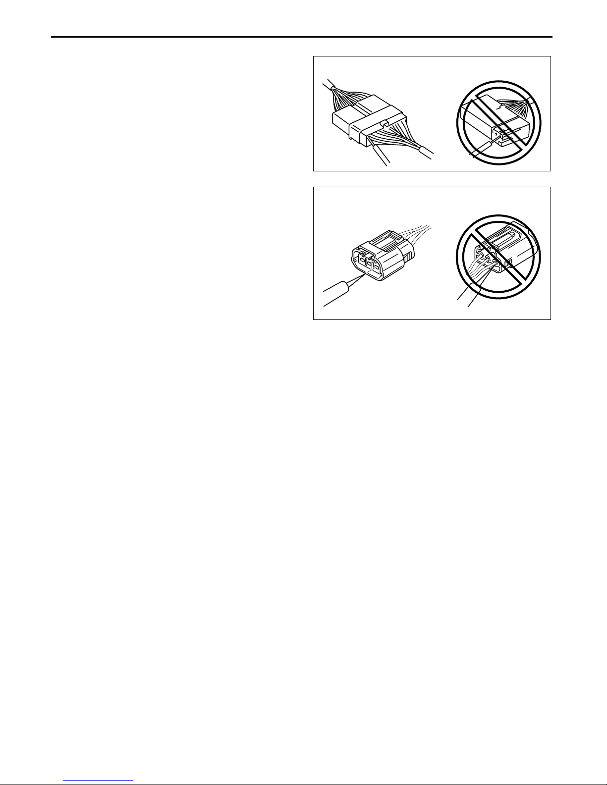
Connectors
Disconnecting connectors
• When disconnecting connector, grasp the
connectors, not the wires.
PROTECTIVE PLATES
GOOD
00–00
CHU0014W010
CHU000000006E01
NO GOOD
• Connectors can be disconnected by pressing or
pulling the lock lever as shown.
Locking connector
• When locking connectors, listen for a click
indicating they are securely locked.
CHU0000W014
WGIWXX0042E
WGIWXX0043E
00–00–9
Page 11
GENERAL INFORMATION
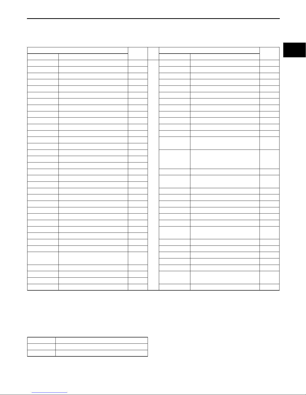
Inspection
• When a tester is used to inspect for continuity or
measuring voltage, insert the tester probe from
the wiring harness side.
• Inspect the terminals of waterproof connectors
from the connector side since they cannot be
accessed from the wiring harness side.
Caution
•
• To prevent damage to the terminal, wrap
••
a thin wire around the tester probe before
inserting into terminal.
End Of Sie
GOOD
NO GOOD
GOOD NO GOOD
CHU0000W011
CHU0000W012
00–00–10
Page 12
Engine Workshop Manual 13B-MSP (Multi Side Port) (1773–1U–03C)
GENERAL INFORMATION
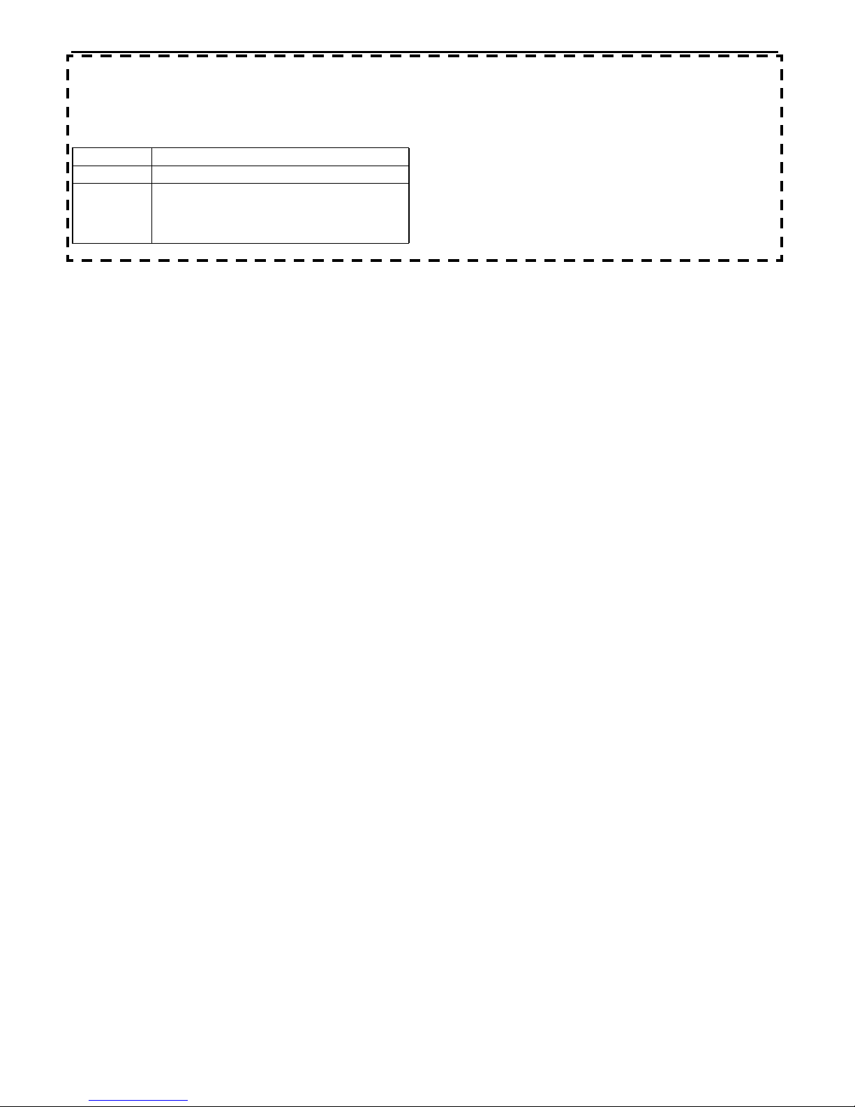
SAE STANDARDS
CHU000000003E02
• In accordance with new regulations, SAE (Society of Automotive Engineers) standard names and abbreviations
are now used in this manual. The table below lists the names and abbreviations that have been used in Mazda
manuals up to now and their SAE equivalents.
SAE Standard
Abbreviation Name Abbreviation Name
AP Accelerator Pedal MAP Manifold Absolute Pressure
APP Accelerator Pedal Position MAF Mass Air Flow
ACL Air Cleaner MAF sensor Mass Air Flow Sensor
A/C Air Conditioning MFL Multiport Fuel Injection
A/F Air Fuel Ratio OBD On-board Diagnostic System
BARO Barometric Pressure OL Open Loop
B+ Battery Positive Voltage OC Oxidation Catalytic Converter
CMP sensor Camshaft Position Sensor O2S Oxygen Sensor
LOAD Calculated Load Value PNP Park/Neutral Position
CAC Charge Air Cooler PID Parameter Identification
CLS Closed Loop System PSP Power Steering Pressure
CTP Closed Throttle Position PCM Powertrain Control Module #3
CPP Clutch Pedal Position
CIS Continuous Fuel Injection System
CKP sensor Crankshaft Position Sensor
DLC Data Link Connector
DTM Diagnostic Test Mode #1
DTC Diagnostic Test Code(s) SAPV Secondary Air Pulse Valve
DI Distributor Ignition
DLI Distributorless Ignition
EI Electronic Ignition #2 3GR Third Gear
ECT Engine Coolant Temperature TWC Three Way Catalytic Converter
EM Engine Modification TB Throttle Body
EVAP Evaporative Emission TP Throttle Position
EGR Exhaust Gas Recirculation TP sensor Throttle Position Sensor
FC Fan Control TCC Torque Converter Clutch
FF Flexible Fuel
4GR Fourth Gear
GEN Generator TR Transmission (Transaxle) Range
GND Ground TC Turbocharger
HO2S Heated Oxygen Sensor
IAC Idle Air Control VAF sensor Volume Air Flow Sensor
IAT Intake Air Temperature
KS Knock Sensor
MIL Malfunction Indicator Lamp WOP Wide Open Throttle
Remark
With
heater
PAIR Pulsed Secondary Air Injection
AIR Secondary Air Injection
SFI
TCM
VSS Vehicle Speed Sensor
VR Voltage Regulator
WU-TWC
SAE Standard
Sequential Multiport Fuel
Injection
Transmission (Transaxle) Control
Module
Warm Up Three Way Catalytic
Converter
Remark
Pulsed
injection
Injection
with air
pump
#4
00–00
#1 : Diagnostic trouble codes depend on the diagnostic test mode.
#2 : Controlled by the PCM
#3 : Device that controls engine and powertrain
#4 : Directly connected to exhaust manifold
End Of Sie
ABBREVIATIONS
AT Automatic Transmission
MT Manual Transmission
SST Special Service Tool
End Of Sie
CHU000000011E01
00–00–11
Page 13
Engine Workshop Manual 13B-MSP (Multi Side Port) (1773–1U–03C)
GENERAL INFORMATION
IDENTIFYING SPECIFICATION
CHU000000000E01
• Because the engine construction varies depending on the vehicle’s period of manufacture, determine the
service specification by referring to the following identification.
Identifying Specification
Applicable VIN
Type A Except below
JM1 FE172*9# 400001—
Type B
End Of Sie
JM1 FE174*9# 400001—
JM1 FE17M*9# 400001—
JM1 FE17P*9# 400001—
00–00–12
Added 6/2008 (Ref. No. R108/08)
Page 14
Engine Workshop Manual 13B-MSP (Multi Side Port) (1773–1U–03C)
MECHANICAL
To c o f S C T
MECHANICAL . . . . . . . . . . . . . 01-10
TECHNICAL DATA. . . . . . . . . . 01-50
To c o f S C T
01–10 MECHANICAL
ENGINE OVERHAUL SERVICE
WARNING . . . . . . . . . . . . . . . . . . . . . . . 01–10–2
ENGINE MOUNTING/DISMOUNTING . . 01–10–2
Mounting . . . . . . . . . . . . . . . . . . . . . . . 01–10–2
Dismounting . . . . . . . . . . . . . . . . . . . . . 01–10–3
HOUSING DISASSEMBLY I . . . . . . . . . . 01–10–4
Oil Pan Disassembly Note . . . . . . . . . . 01–10–5
Oil Pan Upper Block
Disassembly Note . . . . . . . . . . . . . . . 01–10–5
HOUSING DISASSEMBLY II. . . . . . . . . . 01–10–6
Pulley Lockbolt Disassembly Note . . . . 01–10–7
Front Cover Disassembly Note . . . . . . 01–10–7
Oil Pump Sprocket
Disassembly Note . . . . . . . . . . . . . . . 01–10–7
HOUSING DISASSEMBLY III . . . . . . . . . 01–10–8
Flywheel (MT), Counterweight (AT)
Disassembly Note . . . . . . . . . . . . . . . 01–10–9
Tension Bolt Disassembly Note . . . . . . 01–10–10
Rear Housing Disassembly Note . . . . . 01–10–10
Stationary Gear Disassembly Note . . . 01–10–10
Tubular Dowel Disassembly Note. . . . . 01–10–10
Rotor Housing Disassembly Note . . . . 01–10–11
Rotor Disassembly Note . . . . . . . . . . . 01–10–11
Intermediate Housing
Disassembly Note . . . . . . . . . . . . . . . 01–10–12
ROTOR DISASSEMBLY . . . . . . . . . . . . . 01–10–12
Oil Seal Disassembly Note. . . . . . . . . . 01–10–13
Oil Seal Spring Disassembly Note . . . . 01–10–13
SIDE HOUSING (FRONT, INTERMEDIATE,
REAR) INSPECTION. . . . . . . . . . . . . . . 01–10–13
ROTOR HOUSING INSPECTION . . . . . . 01–10–14
ROTOR INSPECTION . . . . . . . . . . . . . . . 01–10–15
APEX SEAL INSPECTION . . . . . . . . . . . 01–10–16
SIDE SEAL INSPECTION . . . . . . . . . . . . 01–10–17
CUT-OFF SEAL INSPECTION . . . . . . . . 01–10–18
OIL SEAL INSPECTION . . . . . . . . . . . . . 01–10–18
SPRING INSPECTION . . . . . . . . . . . . . . 01–10–18
Oil Seal Spring . . . . . . . . . . . . . . . . . . . 01–10–18
Cut-off Seal Spring. . . . . . . . . . . . . . . . 01–10–19
Side Seal Spring . . . . . . . . . . . . . . . . . 01–10–19
Corner Seal Spring . . . . . . . . . . . . . . . 01–10–19
Apex Seal Spring . . . . . . . . . . . . . . . . . 01–10–19
ROTOR BEARING OIL CLEARANCE
INSPECTION . . . . . . . . . . . . . . . . . . . . . 01–10–20
ROTOR BEARING REPLACEMENT. . . . 01–10–21
Removal. . . . . . . . . . . . . . . . . . . . . . . . 01–10–21
Installation . . . . . . . . . . . . . . . . . . . . . . 01–10–21
ECCENTRIC SHAFT INSPECTION . . . . 01–10–22
ECCENTRIC SHAFT END PLAY
INSPECTION . . . . . . . . . . . . . . . . . . . . . 01–10–22
SERVICE TOOLS . . . . . . . . . . . 01-60
01–10
PILOT BEARING
INSPECTION/REPLACEMENT [MT] . . .01–10–24
Inspection . . . . . . . . . . . . . . . . . . . . . . . 01–10–24
Replacement . . . . . . . . . . . . . . . . . . . . . 01–10–24
ECCENTRIC SHAFT BYPASS
VALVE. . . . . . . . . . . . . . . . . . . . . . . . . . . 01–10–25
ECCENTRIC SHAFT POSITION PLATE
INSPECTION . . . . . . . . . . . . . . . . . . . . . 01–10–25
MAIN BEARING OIL CLEARANCE
INSPECTION . . . . . . . . . . . . . . . . . . . . . 01–10–25
MAIN BEARING REPLACEMENT . . . . . .01–10–26
Removal . . . . . . . . . . . . . . . . . . . . . . . . 01–10–26
Installation . . . . . . . . . . . . . . . . . . . . . . . 01–10–27
OIL PUMP INSPECTION . . . . . . . . . . . . . 01–10–29
Typ e A . . . . . . . . . . . . . . . . . . . . . . . . . . 01–10–29
Typ e B . . . . . . . . . . . . . . . . . . . . . . . . . . 01–10–29
ROTOR ASSEMBLY . . . . . . . . . . . . . . . . . 01–10–30
Oil Seal Spring Assembly Note . . . . . . . 01–10–30
O-Ring Assembly Note . . . . . . . . . . . . . 01–10–31
Oil Seal Assembly Note . . . . . . . . . . . . 01–10–32
Cut-Off Seal Spring Assembly Note . . .01–10–32
Cut-Off Seal Assembly Note . . . . . . . . . 01–10–33
HOUSING ASSEMBLY I . . . . . . . . . . . . . . 01–10–34
Thrust Plate Assembly Note . . . . . . . . . 01–10–35
Rotor Assembly Note . . . . . . . . . . . . . . 01–10–35
Oil Jet Plug Assembly Note. . . . . . . . . . 01–10–36
Rotor Housing Assembly Note . . . . . . . 01–10–37
Intermediate Housing
Assembly Note . . . . . . . . . . . . . . . . . . 01–10–38
Rear Oil Seal Assembly Note . . . . . . . . 01–10–39
Rear Housing Assembly Note . . . . . . . . 01–10–40
Tension Bolt Assembly Note . . . . . . . . . 01–10–40
Flywheel (MT), Counterweight (AT)
Assembly Note . . . . . . . . . . . . . . . . . . 01–10–41
HOUSING ASSEMBLY II . . . . . . . . . . . . . 01–10–42
Spacer Assembly Note . . . . . . . . . . . . . 01–10–43
Oil Pump Drive Gear
Assembly Note . . . . . . . . . . . . . . . . . . 01–10–43
Oil Pump Sprocket Wheel
Assembly Note . . . . . . . . . . . . . . . . . . 01–10–43
Front Oil Seal Assembly Note . . . . . . . . 01–10–43
Front Cover Assembly Note . . . . . . . . . 01–10–44
Pulley Lockbolt Assembly Note . . . . . . . 01–10–44
HOUSING ASSEMBLY III . . . . . . . . . . . . . 01–10–45
Oil Pan Upper Block
Assembly Note . . . . . . . . . . . . . . . . . . 01–10–47
Oil Pan Assembly Note . . . . . . . . . . . . . 01–10–47
End of Toc
Revised 6/2008 (Ref. No. R108/08)
01–10–1
Page 15
Engine Workshop Manual 13B-MSP (Multi Side Port) (1773–1U–03C)
MECHANICAL
ENGINE OVERHAUL SERVICE WARNING
Warning
• Continuous exposure to USED engine oil has caused skin cancer in laboratory mice. Protect your
skin by washing with soap and water immediately after this work.
End Of Sie
ENGINE MOUNTING/DISMOUNTING
Caution
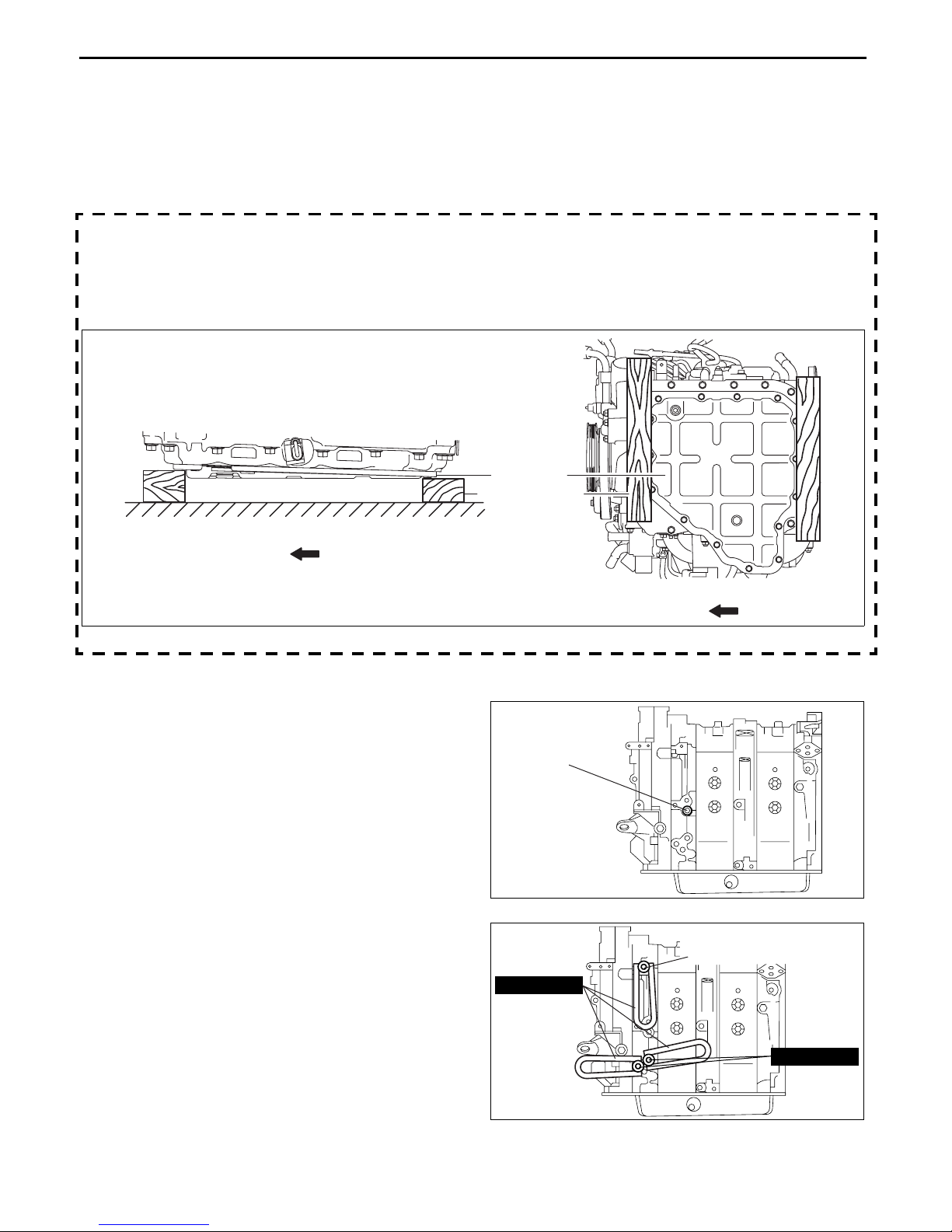
• The oil pan could be damaged or dented if the engine's own weight is subjected to an impact
against a level surface. Always set two pieces of wood in the positions shown in the figure to
prevent the oil pan from being dented. If the oil pan is dented, the amount of intake oil and the fluid
pressure will decrease. (Type B)
OIL PAN
PIECE OF WOOD
CHU011002000E01
CHU011002000E12
ENGINE FRONT SIDE
Mounting
Using 49 L010 1A0
1. Remove the stud bolt.
2. Install the SSTs (arms) to the specified three
position as shown in the figure, and temporarily
tighten with the SSTs (bolts) and 99784 0890 or
M8×1.25 length 90 mm {3.55 in} bolt.
ENGINE FRONT SIDE
GHE0110E001
STUD BOLT
TT
LL
CHU0110E048
99784 0890 OR M8x1.25
LENGTH 90 mm {3.55 in} BOLT
49 L010 102
TT
LL
01–10–2
49 L010 107
CHU0110E049
Revised 6/2008 (Ref. No. R108/08)
Page 16
Engine Workshop Manual 13B-MSP (Multi Side Port) (1773–1U–03C)
MECHANICAL
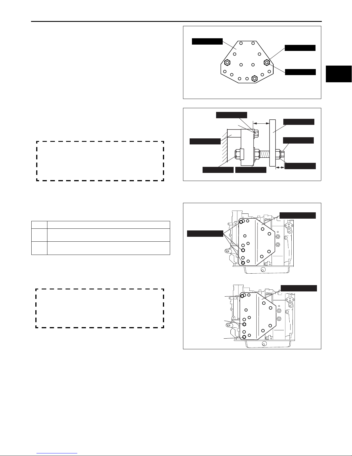
3. Install the SSTs (bolt, nut) to the three specified
positions as shown in the figure.
4. Install the SSTs (bolts, nuts, hook, plate) in Step 3
to the SST (arms, bolts) set in Step 2.
5. Adjust the bolt threads by turning them so that
they project approx. 20 mm {0.79 in} from the
plate end.
6. Adjust the bolts and nuts so that the plate and
arms are parallel.
7. Mount the engine to the SST (engine stand).
8. Remove the oil pan drain plug and drain the
engine oil.
9. Replace with a new washer and install the oil pan
drain plug.
Tightening torque
Type A : 29.4—39.2 N·m {3.00—3.99 kgf·m,
21.7—28.9 ft·lbf}
Type B : 29.4—41.2 N·m {3.00—4.20 kgf·m,
21.7—30.3 ft·lbf}
49 L010 101
49 L010 107
99784 0890 OR M8x1.25
LENGTH 90 mm {0.55 in}
BOLT
49 L010 102
ENGINE
49 L010 10449 L010 103
PARALLEL
APPROX. 20 mm {0.79in}
49 L010 104
49 L010 105
BHJ0110E003
49 L010 101
49 L010 105
49 L010 104
CHU0110E050
01–10
Using 49 J010 3A0A
1. Install the SSTs to the position shown in the
figure.
AM8×1.25 length 25 mm {1.28 in} bolt
99940 1201 (left side engine mount installation nut)
B
or M12×1.5 nut
99756 1230 (left side engine mount installation nut)
C
+ washer
2. Mount the engine to the SST (engine stand).
3. Remove the oil pan drain plug and drain the
engine oil.
4. Install the oil pan drain plug with a new washer.
Tightening torque
Type A : 29.4—39.2 N·m {3.00—3.99 kgf·m,
21.7—28.9 ft·lbf}
Type B : 29.4—41.2 N·m {3.00—4.20 kgf·m,
21.7—30.3 ft·lbf}
WHEN USING 49 J010 3A0A
49 J010 302A
ONLY WHEN USING 49 J010 301A
A
B
C
49 J010 301A
TT
LL
49 J010 301A
TT
LL
CHU0110E058
Dismounting
1. Dismount in the reverse order of mounting.
2. Tighten the stud bolt. (Only when using 49 L010 101.)
Tightening torque
14.7—34.3 N·m {1.50—3.49 kgf·m, 10.9—25.2 ft·lbf}
End Of Sie
Revised 6/2008 (Ref. No. R108/08)
01–10–3
Page 17
Engine Workshop Manual 13B-MSP (Multi Side Port) (1773–1U–03C)
MECHANICAL
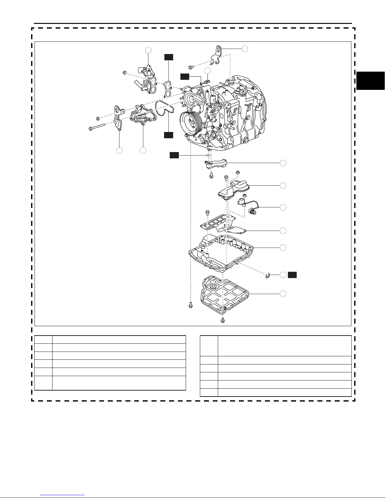
HOUSING DISASSEMBLY I
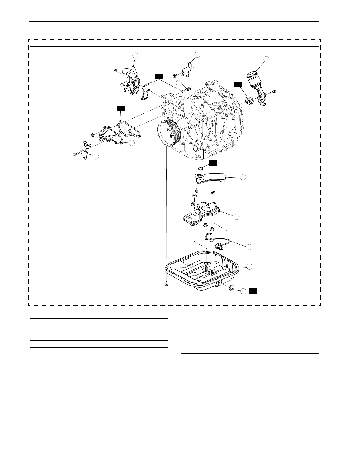
1. Disassemble in the order indicated in the table.
Type A
6
R
5
4
CHU011002000E04
2
1
R
3
R
R
11
.
1 Oil filter component
2 Engine hanger (engine rear side)
3 Engine coolant temperature sensor
4 Engine hanger (engine front side)
5 Water pump body
6 Thermostat component
9
10
7
R
8
7Oil pan
(See 01–10–5 Oil Pan Disassembly Note.)
8 Clip
9 Oil baffle plate
10 Oil-level sensor
11 Oil strainer
BHJ0110E006
01–10–4
Revised 6/2008 (Ref. No. R108/08)
Page 18
01–10-4 MECHANICAL
Typ e B
Engine Workshop Manual 13B-MSP (Multi Side Port) (1773–1U–03C)
MECHANICAL
CHU011002000E04
5
R
1
2
R
R
3
4
R
01–10
12
8
10
11
.
1 Engine hanger (engine rear side)
2 Engine coolant temperature sensor
3 Engine hanger (engine front side)
4 Water pump body
5 Thermostat component
6 Oil pan
(See 01–10–5 Oil Pan Disassembly Note.)
End Of Sie
7
9
R
6
7 Oil pan upper block
(See 01–10–5 Oil Pan Upper Block Disassembly
Note.)
8 Baffle plate
9 Clip
10 Oil level switch
11 Baffle plate
12 Oil strainer
BHJ0110F002
Revised 6/2008 (Ref. No. R108/08)
01–10-4–1
Page 19

Engine Workshop Manual 13B-MSP (Multi Side Port) (1773–1U–03C)
MECHANICAL
THIS PAGE INTENTIONALLY
LEFT BLANK
01–10-4–2
Page 20

Engine Workshop Manual 13B-MSP (Multi Side Port) (1773–1U–03C)
Oil Pan Disassembly Note
1. Remove the oil pan using the separator tool.
Oil Pan Upper Block Disassembly Note
1. Remove the oil pan upper block using the
separator tool.
End Of Sie
MECHANICAL
01–10
BHJ0111W014
BHJ0111E014
Revised 6/2008 (Ref. No. R108/08)
01–10–5
Page 21
Engine Workshop Manual 13B-MSP (Multi Side Port) (1773–1U–03C)
MECHANICAL
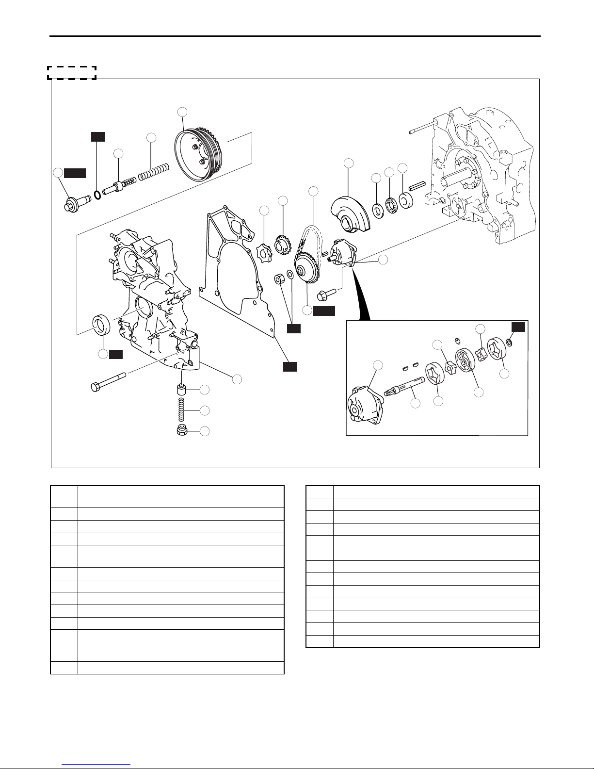
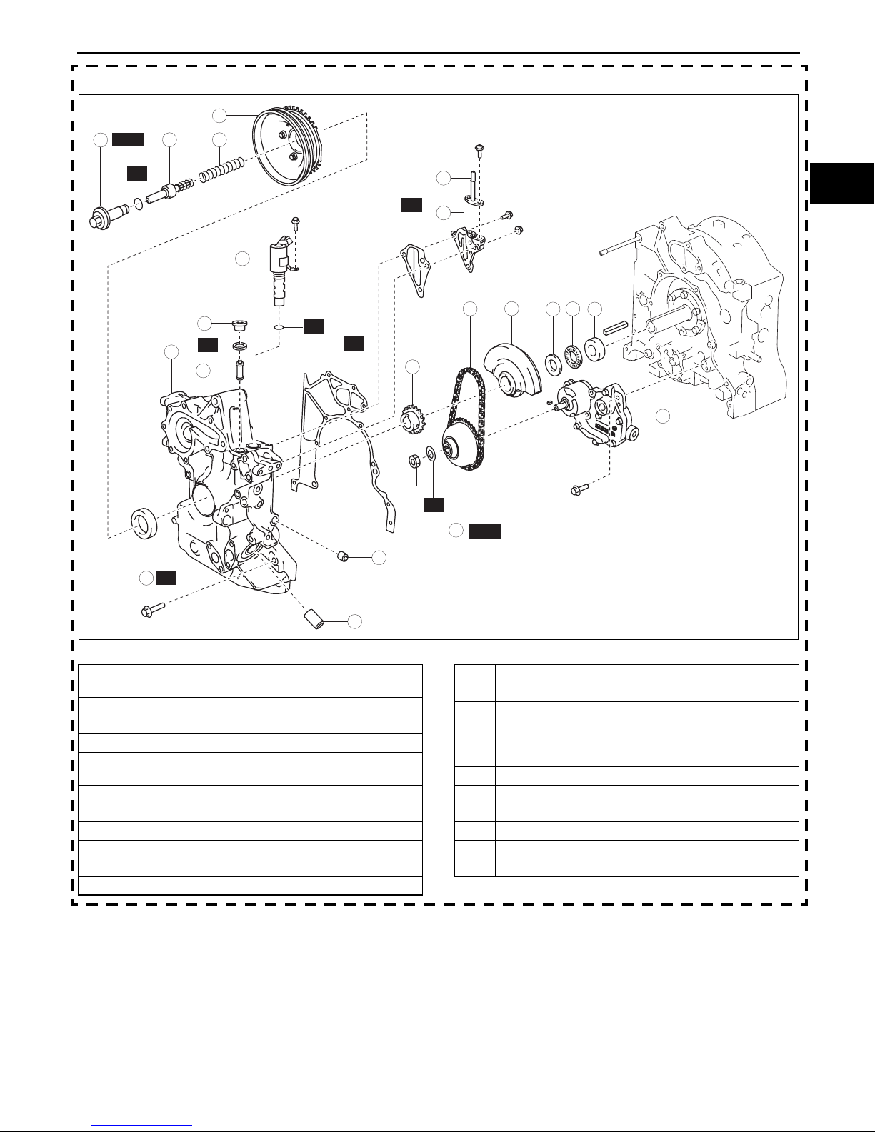
HOUSING DISASSEMBLY II
1. Disassemble in the order indicated in the table.
Type A
2
R
4
3
1
SST
6
R
5
9
8
10
13
CHU011002000E05
15
16
17
18
12
14
11
SST
R
20
R
23
R
25
19
21
22
24
.
1 Pulley lockbolt
(See 01–10–7 Pulley Lockbolt Disassembly Note.)
2 Pulley component
3 Eccentric shaft bypass valve
4Spring
5 Front cover
(See 01–10–7 Front Cover Disassembly Note.)
6 Front oil seal
7Plug
8 Control valve spring
9 Control valve
10 Metering oil pump drive gear
11 Oil pump sprocket wheel
(See 01–10–7 Oil Pump Sprocket Disassembly
Note.)
12 Oil pump chain
7
BHJ0110E008
13 Oil pump drive gear
14 Oil pump component
15 Balance weight
16 Thrust plate
17 Needle bearing
18 Spacer
19 Rear outer rotor
20 Rear inner rotor
21 Middle plate
22 Front outer rotor
23 Front inner rotor
24 Shaft
25 Oil pump body
01–10–6
Revised 6/2008 (Ref. No. R108/08)
Page 22
01–10-6 MECHANICAL
Typ e B
SST
1
Engine Workshop Manual 13B-MSP (Multi Side Port) (1773–1U–03C)
MECHANICAL
CHU011002000E04
2
43
R
8
R
9
01–10
7
15 18 192021
10
R
5
11
R
R
16
17
R
14
SST
13
6
R
.
1 Pulley lockbolt
(See 01–10–7 Pulley Lockbolt Disassembly Note.)
2 Pulley component
3 Eccentric shaft bypass valve
4Spring
5 Front cover
(See 01–10–7 Front Cover Disassembly Note.)
6 Front oil seal
7OCV
8 Oil pipe
9 OCV case
10 Plug
11 OCV oil filter
End Of Sie
12
BHJ0110F003
12 Oil filter joint
13 Plug
14 Oil pump sprocket wheel
(See 01–10–7 Oil Pump Sprocket Disassembly
Note.)
15 Oil pump chain
16 Oil pump drive gear
17 Oil pump component
18 Balance weight
19 Thrust plate
20 Needle bearing
21 Spacer
Revised 6/2008 (Ref. No. R108/08)
01–10-6–1
Page 23

Engine Workshop Manual 13B-MSP (Multi Side Port) (1773–1U–03C)
MECHANICAL
THIS PAGE INTENTIONALLY
LEFT BLANK
01–10-6–2
Page 24
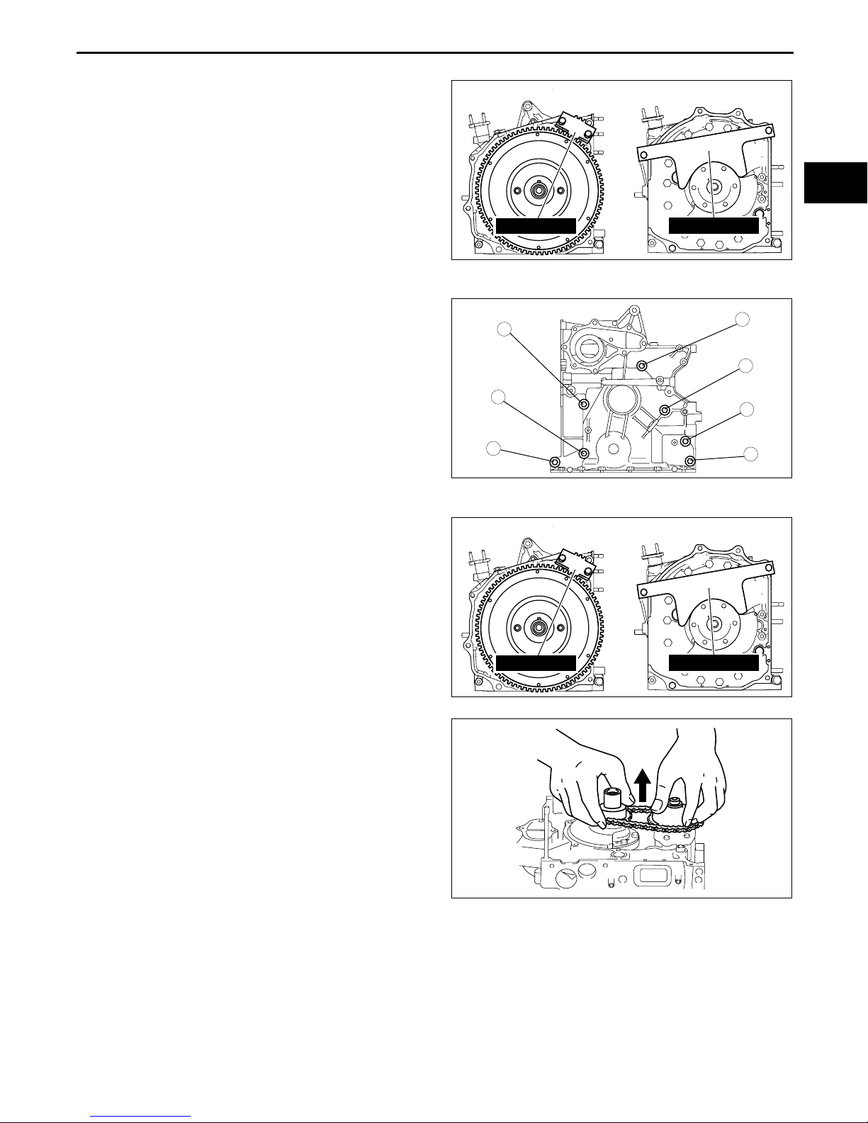
Pulley Lockbolt Disassembly Note
1. Lock the flywheel (MT) or counte r w eight (AT)
against rotation using the SST.
MECHANICAL
MT
AT
01–10
Front Cover Disassembly Note
1. Loosen the engine front cover installation bolts in
the order shown in the figure.
Oil Pump Sprocket Disassembly Note
1. Lock the flywheel (MT) or counte r w eight (AT)
against rotation using the SST.
2. Unlock the crimped part of the lock washer and
remove the locknut and lock washer.
MT
49 F011 101
5
7
3
49 1881 055A
BHJ0110E007
1
6
4
2
BHJ0110E009
AT
3. Remove the oil pump drive gear and oil pump
sprocket wheel with the oil pump chain engaged.
End Of Sie
49 F011 101
49 1881 055A
BHJ0110E007
BHJ0110E104
01–10–7
Page 25
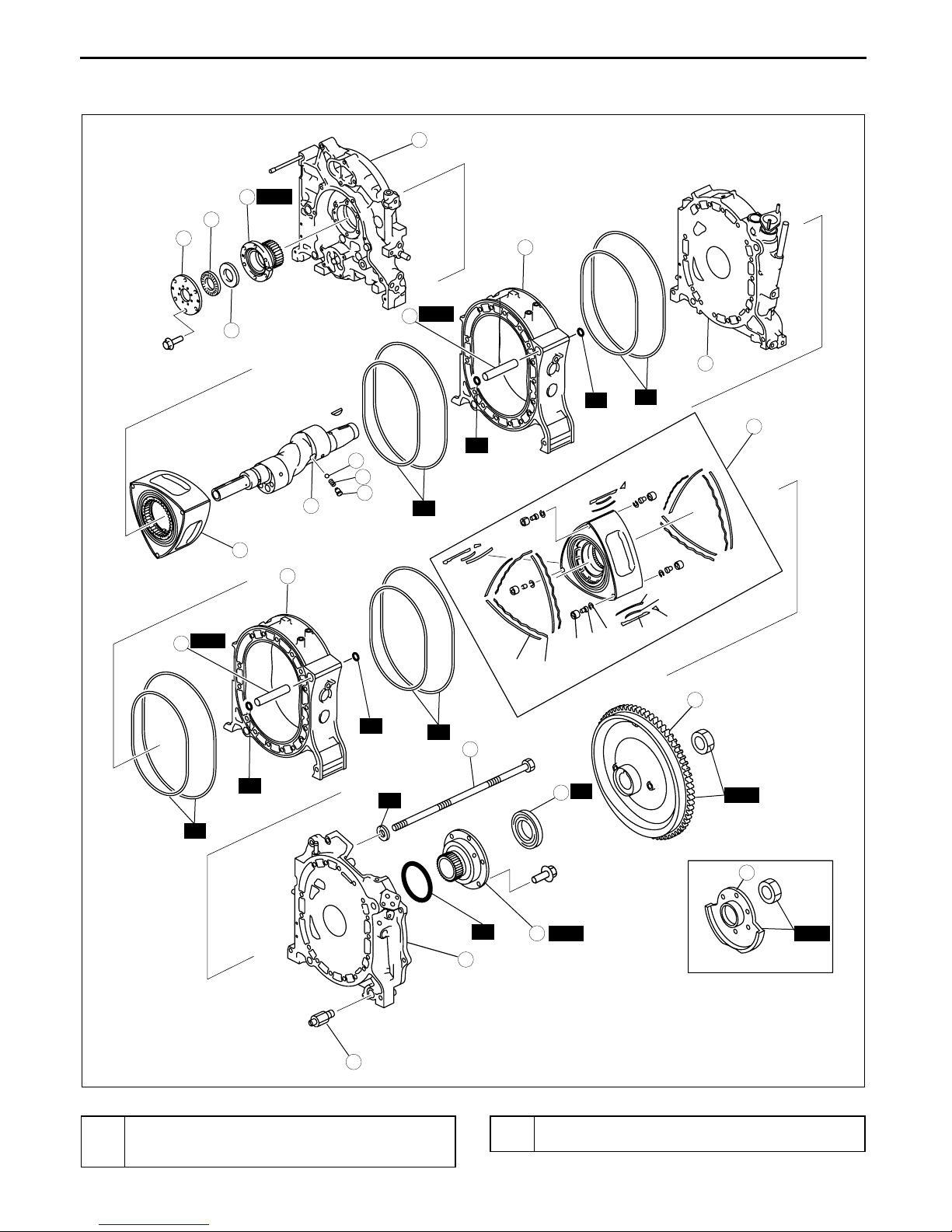
MECHANICAL
HOUSING DISASSEMBLY III
1. Disassemble in the order indicated in the table.
SST
21
19
18
10
20
16
15
14
13
22
R
SST
CHU011002000E06
12
11
R
R
9
R
17
8
SST
7
A
B
D
C
I
H
E
F
G
1
R
R
2
R
R
R
R
R
4
SST
5
AT
SST
1
SST
3
.
1 Flywheel (MT), counterweight (AT)
(See 01–10–9 Flywheel (MT), Counterweight (AT)
Disassembly Note.)
01–10–8
6
BHJ0110E010
Tension bolt
2
(See 01–10–10 Tension Bolt Disassembly Note.)
Page 26
Engine Workshop Manual 13B-MSP (Multi Side Port) (1773–1U–03C)
MECHANICAL
3 Rear housing
(See 01–10–10 Rear Housing Disassembly Note.)
4 Rear oil seal
5 Rear stationary gear
(See 01–10–10 Stationary Gear Disassembly Note.)
6 Pressure regulator (Type A)
7 Tubular dowel (rear rotor housing side)
(See 01–10–10 Tubular Dowel Disassembly Note.)
8 Rear rotor housing
(See 01–10–11 Rotor Housing Disassembly Note.)
9 Rear rotor
A: Side seal
B: Side seal spring
C: Corner seal
D: Corner seal plug
E: Corner Seal Spring
F: Side piece
G: Apex seal
H: Apex seal spring (short)
I: Apex seal spring (long)
(See 01–10–11 Rotor Disassembly Note.)
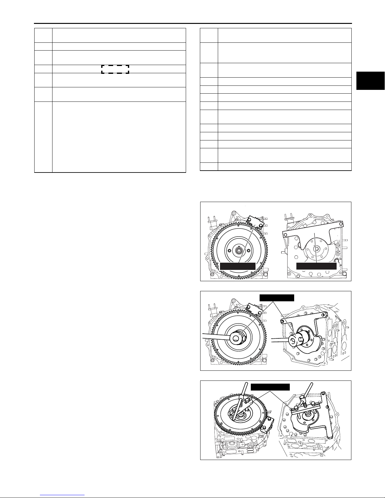
Flywheel (MT), Counterweight (AT) Disassembly Note
1. Lock the flywheel (MT) or counterweight (AT)
against rotation using the SST.
10 Tubular dowel (front rotor housing side)
(See 01–10–10 Tubular Dowel Disassembly Note.)
11 Intermediate housing
(See 01–10–12 Intermediate Housing Disassembly
Note.)
12 Front rotor housing
(See 01–10–11 Rotor Housing Disassembly Note.)
13 Eccentric shaft
14 Oil jet plug
15 Spring
16 Steel ball
17 Front rotor
(See 01–10–11 Rotor Disassembly Note.)
18 Plate
19 Needle bearing
20 Thrust plate
21 Front stationary gear
(See 01–10–10 Stationary Gear Disassembly Note.)
22 Front housing
MT
AT
01–10
2. Remove the locknut using the SST.
3. Remove the flywheel (MT) or counterweight (AT),
using the SST.
49 F011 101
MT
MT
49 0820 035
49 0839 305A
49 1881 055A
BHJ0110E007
AT
BHJ0110E011
AT
Revised 6/2008 (Ref. No. R108/08)
BHJ0110E012
01–10–9
Page 27
Engine Workshop Manual 13B-MSP (Multi Side Port) (1773–1U–03C)
MECHANICAL
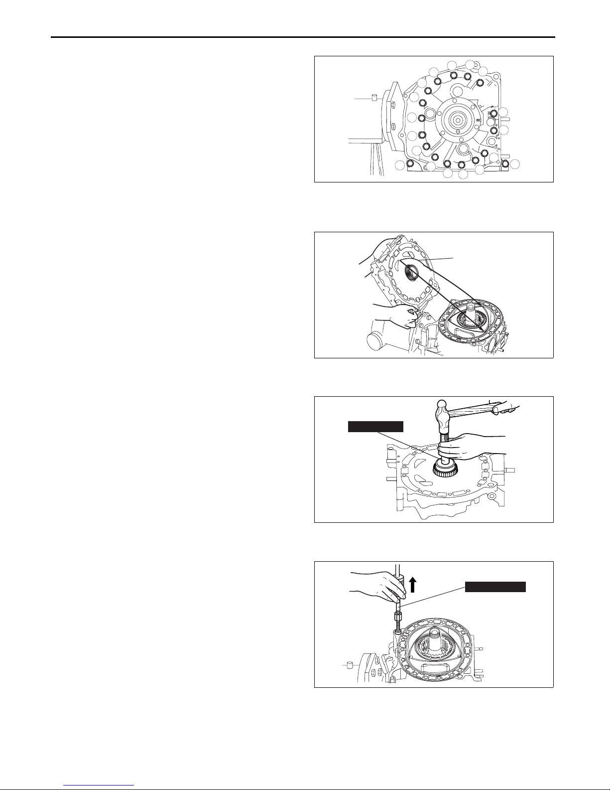
Tension Bolt Disassembly Note
1. Loosen the tension bolts in 2⎯3 passes in the
order shown in the figure and remove them.
Rear Housing Disassembly Note
1. Move the rear housing to the left and right to cut the oil film.
2. Remove the rear housing.
6
3
7
10
11
15
18
16
12
2
8
4
5
14
17
13
9
1
BHJ0110E013
Caution
• If a seal adheres to the rear housing, put
it back in its original position in the rotor.
Stationary Gear Disassembly Note
1. Remove the stationary gear using the SST.
SEAL
CHU0110E039
49 0813 235
BHJ0110E016
Tubular Dowel Disassembly Note
1. Remove the tubular dowel using the SST.
01–10–10
49 0813 215A
BHJ0110E017
Page 28
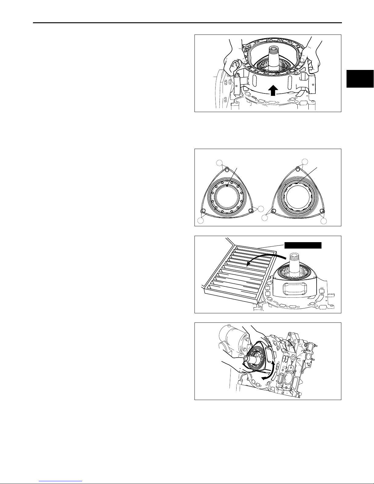
Rotor Housing Disassembly Note
1. Remove the rotor housing bei ng ca re ful not to
drop the apex seal.
Rotor Disassembly Note
Note
• Pair each seal and spring according to the
numbers shown in the figure, and place
them in the SST according to the numbers
shown on the SST.
MECHANICAL
INTERNAL GEAR SIDE
1
ROTATION LOCK TAB
01–10
BHJ0110E020
OPPOSITE INTERNAL GEAR SIDE
2
TAB
1. Remove the side piece, ape x sea l, corner se al,
side seal, and spring on the engine rear side, and
place them in the SST while keeping them in
order.
2. Move the rotor to the left and right to cut the oil
film.
3. Remove the rotor.
Caution
•
• If a seal adheres to the side housing, put
••
it back in its original position in the rotor.
•
• Place the removed rotor upright on soft
••
material such as a rubber sheet or cloth.
Do not allow the oil seal to directly
contact metal are similar hard surface.
5
3
6
49 0813 250
4
CHU0110E056
BHJ0110E019
BHJ0110E021
01–10–11
Page 29
MECHANICAL
4. Remove the corner seal, side seal, and spring on
the engine front side, and plac e them in the SST
while keeping them in order .
Intermediate Housing Disassembly Note
1. Lift the intermediate housing up while another
person pushes the eccentric shaft upward
approx. 3 cm {1.18 in} .
2. Rotate and remove the intermediate housing at
the point where the eccentric shaft does not
catch.
Caution
•
• If a seal adheres to the intermediate
••
housing, put it back in its original
position in the rotor.
End Of Sie
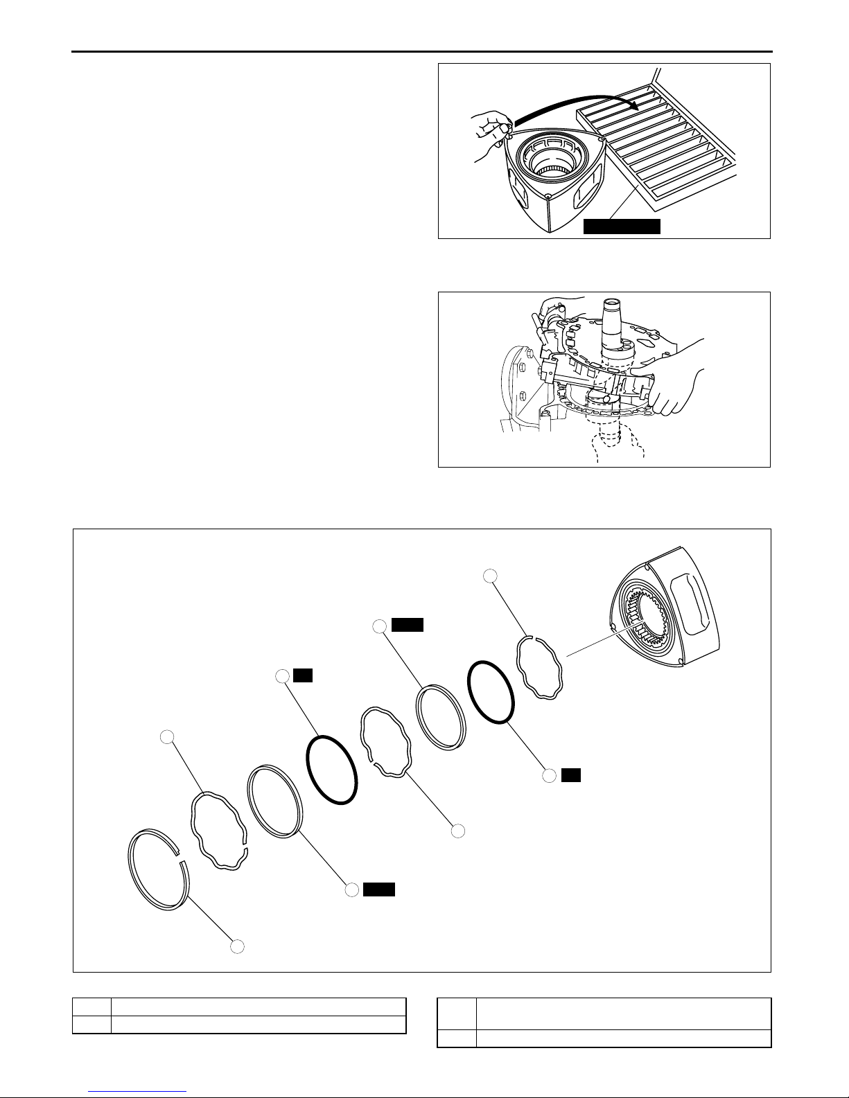
ROTOR DISASSEMBLY
1. Disassemble in the order indicated in the table.
49 0813 250
BHJ0110E022
BHJ0110E023
CHU011002000E07
2
.
1Cut-off seal
2 Cut-off seal spring
8
SST
6
R
4
R
7
5
SST
3
1
BHJ0110E024
3 Outer oil seal
(See 01–10–13 Oil Seal Disassembly Note.)
4 Outer O-ring (large radius)
01–10–12
Page 30
MECHANICAL
5 Outer oil seal spring
(See 01–10–13 Oil Seal Spring Disass em bly Note.)
6 Inner oil seal
(See 01–10–13 Oil Seal Disasse mb ly N ote. )
7 Inner O-ring (small radius)
8 Inner oil seal spring
(See 01–10–13 Oil Seal Spring Disassembly No te.)
Oil Seal Disassembly Note
1. Remove the oil seal using th e SST.
Caution
•
• Be sure to keep the removed oil seals
••
49 0813 225A
separated according to their removal
position.
Oil Seal Spring Disassembly Note
Caution
•
• Be sure to keep the removed oil seal springs separated according to their removal positions.
••
End Of Sie
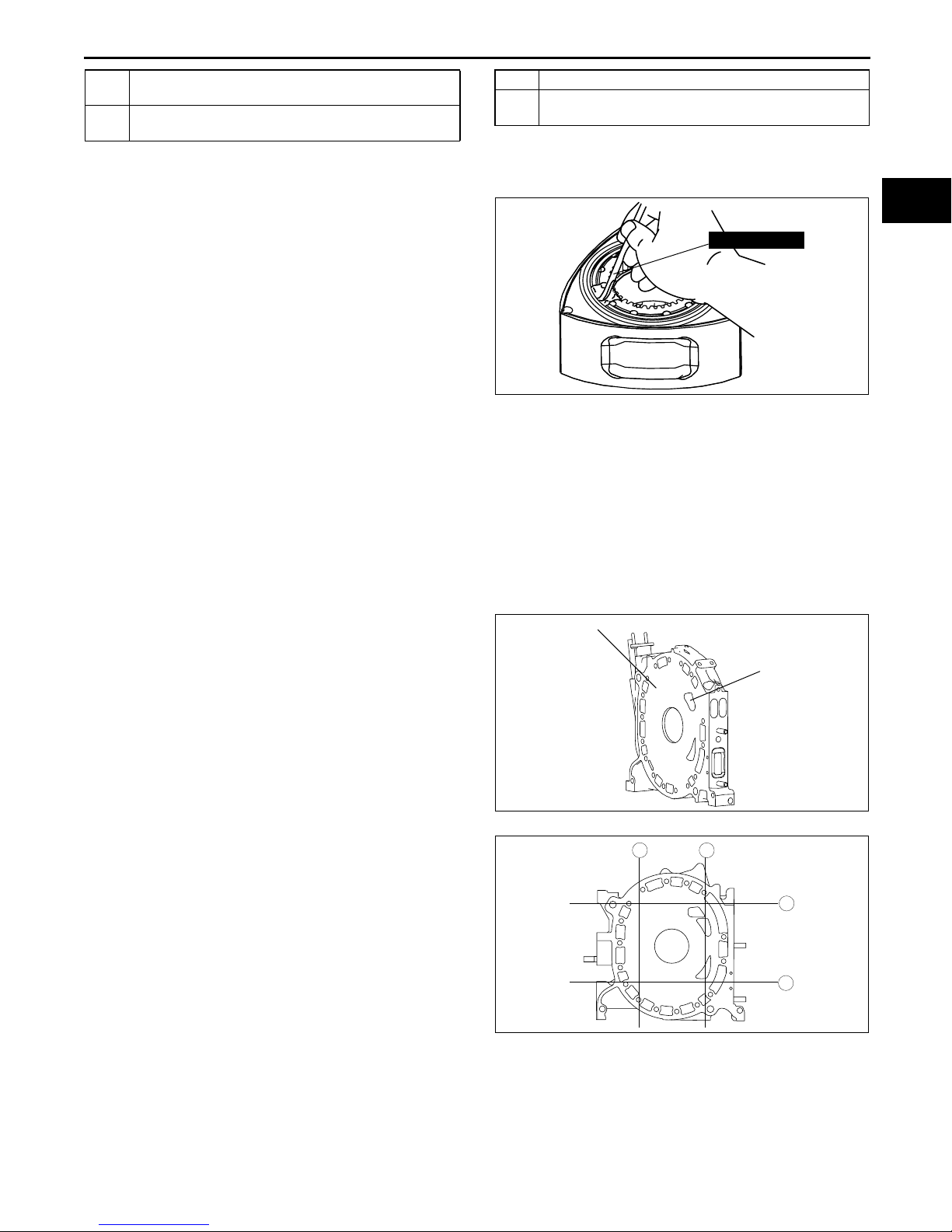
SIDE HOUSING (FRONT, INTERMEDIATE, REAR) INSPECTION
1. Inspect the intermediate housing for clogging in the intake and exhaust port.
01–10
BHJ0110E025
CHU011010D00E01
Caution
•
• Carefully inspect the anti-wet port of the
••
intermediate housing since it is an
essential port.
• If there is any malfunction, replace the
corresponding s ide hou si ng .
2. Inspect the side hou sing for distortion in four
positions as shown in the figure us ing a st rai ght
edge and a feeler gauge.
• If the distortion exceeds the maximum,
replace the corresponding side housing.
Maximum distortion
0.04 mm {0.0016 in}
3. Inspect the following three items related to wear
in the areas where the rotor contacts the side
housing using a dial gauge.
• If any one of the items exceeds the maximum,
replace the corresponding side housing.
INTERMEDIATE HOUSING
ANTI-WET PORT
CHU0110E001
1 2
3
4
BHJ0110E026
01–10–13
Page 31
MECHANICAL
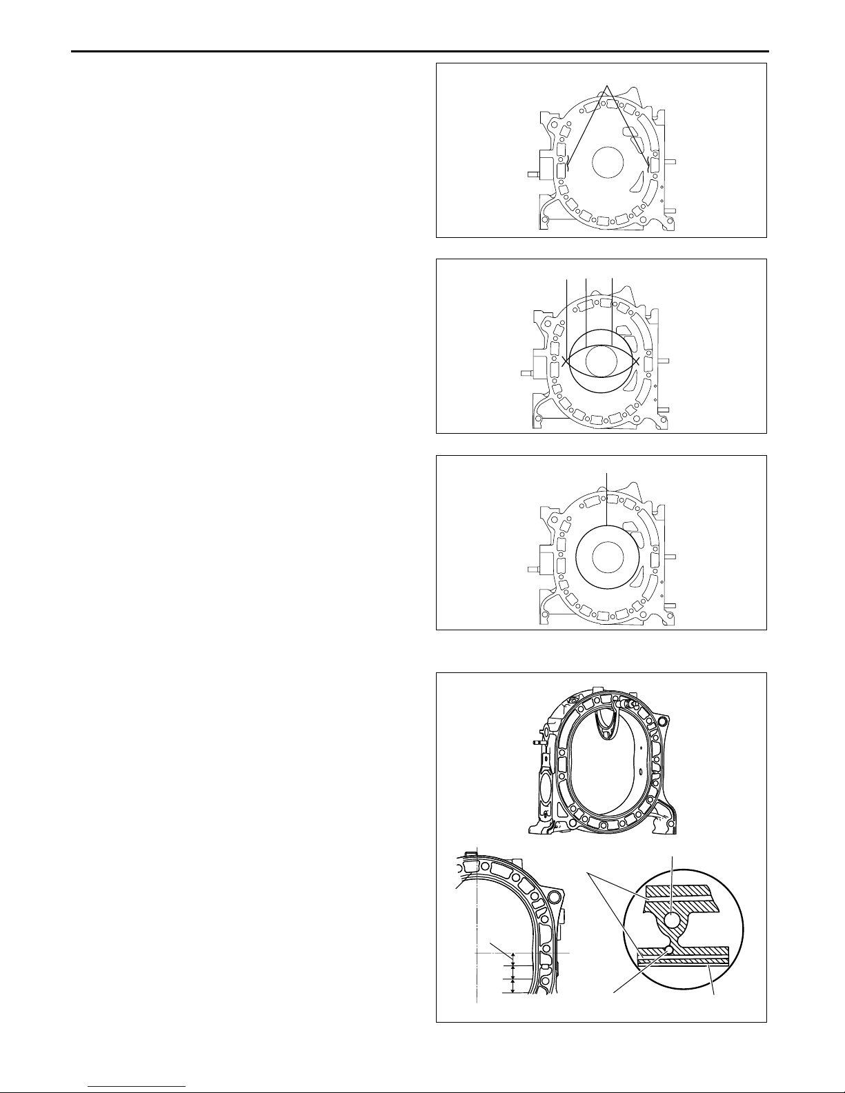
(1) Vertical wear
Maximum wear
0.10 mm {0.0039 in}
(2) Convex oval
Maximum wear
Oil seal inner path (A): 0.01 mm {0.0004 in}
Oil seal outer path (B): 0.10 mm {0.0039 in}
(3) Oil seal stepped path wear
WEAR AREA
OIL SEAL PATH
A
B
WEAR AREA
CHU0110E002
CHU0110E003
Maximum wear
0.02 mm {0.0008 in}
End Of Sie
ROTOR HOUSING INSPECTION
1. Measure the width of the rotor housing at four
points (A, B, C, and D) as shown in the figure
using a micrometer.
2. Compute the width variation.
• If it exceeds the maximum, replace the rotor
housing.
Width difference = (width A) – (the smallest
of widths B, C, or D)
Maximum width difference
0.06 mm {0.0024 in}
End Of Sie
CHU0110E004
CHU011010B08E01
TENSION BOLT HOLE
SEAL RUBBER GROOVE
A
01–10–14
20 mm {0.79 in}
B
C
D
MEASUREMENT POINT
SHEET METAL
CHU0110E005
Page 32
MECHANICAL
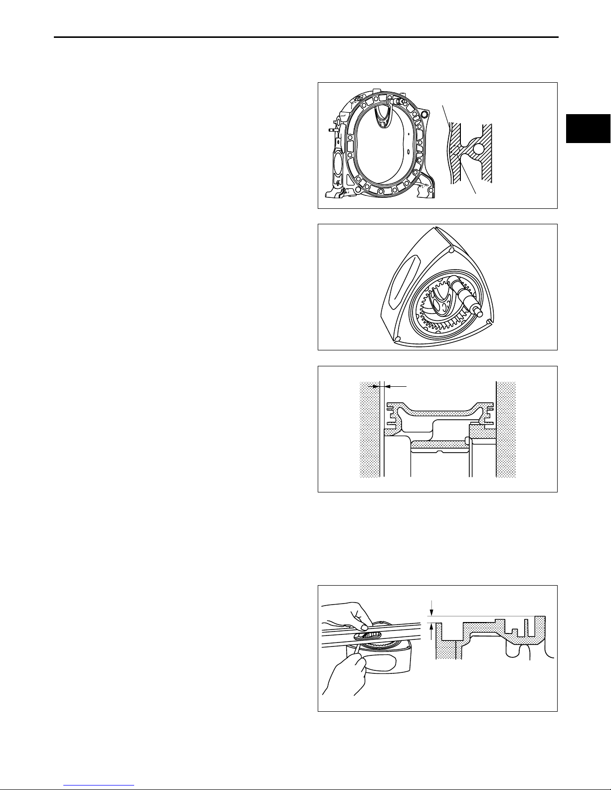
ROTOR INSPECTION
1. Inspect the rotor and side housing clearance according to the following procedure:
• If it is less than the minimum specification, replace the rotor.
(1) Measure the width of the rotor housing in the
position shown in the figure using a
micrometer.
Caution
•
• Move the sheet metal piece out of the
••
way when measuring.
(2) Measure the rotor width at various positions
around the rotor round periphery using a
micrometer.
CHU011011B10E01
SHEET METAL
01–10
MEASUREMENT POINT
CHU0110E040
(3) Compute the rotor and side housing
clearance using the measurements from (1)
and (2).
Rotor and side housing clearance = (rotor
housing width) – (maximum rotor width)
Standard clearance
0.05—0.19 mm {0.0020—0.0074 in}
Minimum clearance
0.05 mm {0.002 in}
2. Measure the protrusion of the rotor round using a
straight edge and a feeler gauge.
Caution
•
• Measure the the protrusion of the rotor round in the three apexes of the rotor on both the front and
••
rear sides.
•
• Because the rotor round has two levels, be careful not to measure the level difference of the
••
middle level.
• If it is less than the minimum specification,
replace the rotor.
Standard projection
0.12—0.18 mm {0.0048—0.0070 in}
Minimum projection
0.1 mm {0.0039 in}
BHJ0110E032
CHU0110E006
CHU0110E007
01–10–15
Page 33
MECHANICAL
3. Inspec t the corner seal groove of the rotor by
inserting the SST.
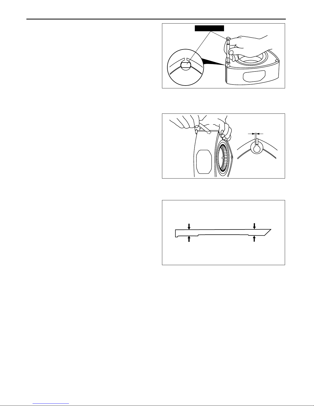
• If 1/ 2 o r m ore of either end of the SST can be
inserted into the seal groove, replace the
corner seal.
• If 1/2 or more of both ends of the SST can be
inserted into t he corner seal groove, replace
the rotor.
Caution
•
• Do not push the SST in with force.
••
•
• Keep the SST perpendicular to the seal
••
groove.
•
• When replacing the corner seal, replace
••
with one that matches the S or L inscription on the rotor.
4. Measure the clearance between the apex seal
groove and the apex seal using a feeler gauge.
• If it exceeds the maximum specification,
replace the apex seal.
• If the clearance is still not with in the standard
after replacing the apex seal, replace the
rotor.
Standard clearance
0.042—0.101 mm {0.0017—0.0039 in}
Maximum clearance
0.15 mm {0.0059 in}
End Of Sie
APEX SEAL INSPECTION
1. Measure the height in the positions shown in the
figure.
• If it is less th an the minimum specification,
replace the apex seal.
• Replace the apex seal spring also whenever
replacing the apex seal.
49 0839 165
BHJ0110E035
CHU0110E008
CHU011011B10E02
Standard Height
5.3 mm {0.20 in}
Minimum height
4.3 mm {0.17 in}
End Of Sie
BHJ0110E037
01–10–16
Page 34
Engine Workshop Manual 13B-MSP (Multi Side Port) (1773–1U–03C)
MECHANICAL
SIDE SEAL INSPECTION
Replacing with a new side seal.
1.
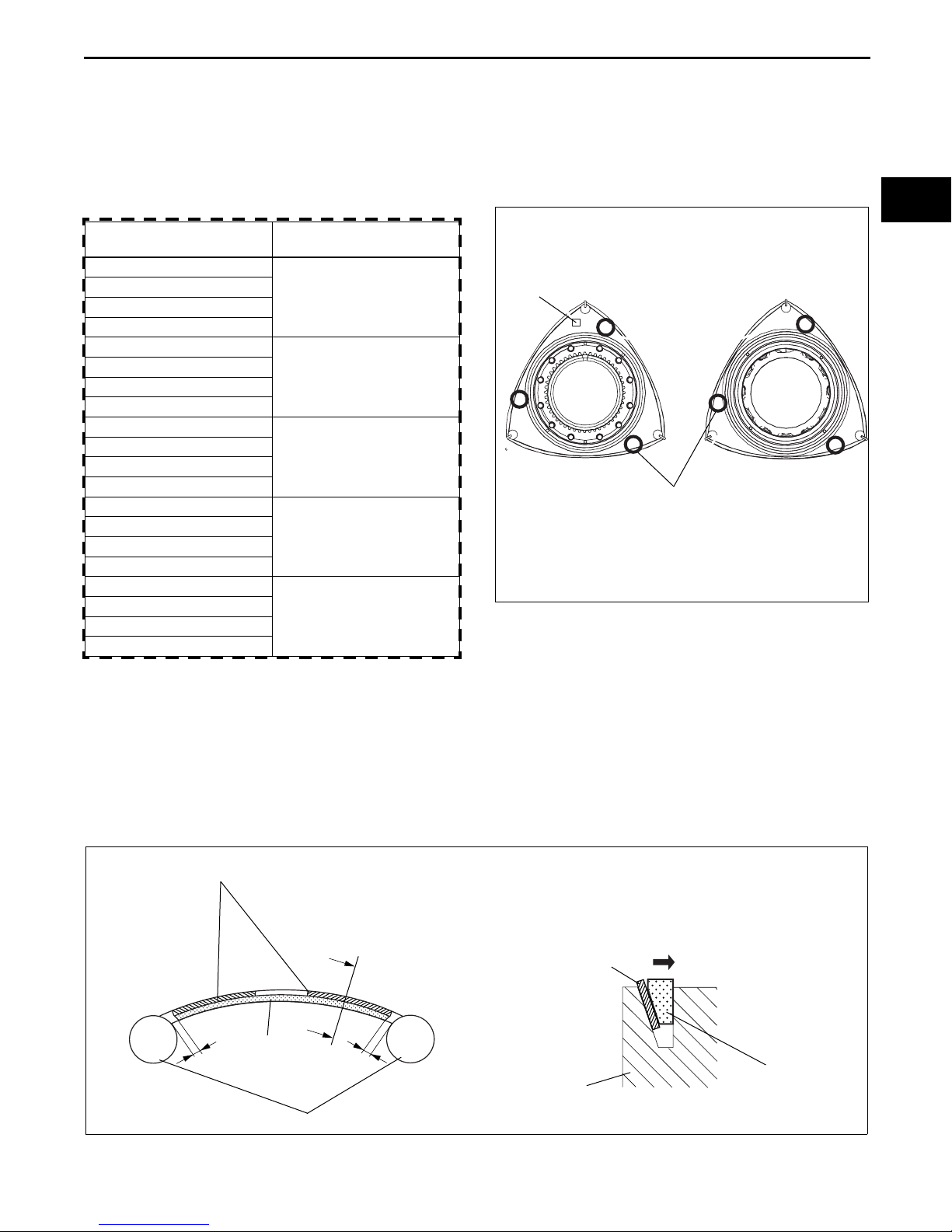
If replacing the side seal, select the appropriate side seal from the side seal groove length rank marked on the
CHU011011B10E04
rotor.
Note
• If a new side seal is inserted, measuring the clearance is not recommended to maintain an appropriate
side seal clearance value.
Side seal selection table
Side seal groove length
rank stamp
F
G
H
I
J
K
L
M
N
O
P
Q
R
S
T
U
V
W
X
Y
Part number of side seal
N3Z1 11 C10
N3Z2 11 C10
N3Z3 11 C10
N3Z4 11 C10
N3Z5 11 C10
*
*
*
*
*
INTERNAL GEAR SIDE
TWO-DIMENSION
BAR CODE
*
s
F
B
F
s
*
SIDE SEAL GROOVE LENGTH RANK STAMP
(A RANK MARK IS STAMPED FOR EACH SIDE SEAL GROOVE)
*: IDENTIFICATION NUMBER (1 OR 2) USED ONLY FOR
LINE ASSEMBLY
OPPOSITE INTERNAL GEAR SIDE
F
s
F
*
s
*
*
s
B
CHU110ZEC001
01–10
F
s
F
*
* : Revision indication (alphabetical order)
Reusing the side seal
1. Measure the side seal and corner seal clearance and verify that it doesn’t exceed the maximum.
(1) Assemble the corner seal.
(2) Insert a 0.15 mm {0.0059 in} feeler gauge into the tapered surface side of the side seal as shown in the
figure, and fix the side seal by pressing uniformly so that it contacts the inner side of the groove (straight
surface).
Caution
• Press the feeler gauge firmly on both ends of the side seal.
(3) Measure the clearance between both ends of the side seal and the corner seal using a feeler gauge.
FEELER GA
(INSERT INTO BOTH ENDS)
UGE
SIDE SEAL
CORNER SEAL
SEC. A-A
A
A
FEELER GAUGE
0.15 mm {0.0059 in}
SIDE SEAL
ROTOR
CHU110ZEC002
Revised 9/2008 (Ref. No. R174/08)
01–10–17
Page 35
Engine Workshop Manual 13B-MSP (Multi Side Port) (1773–1U–03C)
MECHANICAL
(4) If the sum of the clearances on both ends exceeds the maximum, replace with a new side seal by selecting
one from the side seal selection table.
Maximum clearance
0.4 mm {0.016 in}
END OF SIE
CUT-OFF SEAL INSPECTION
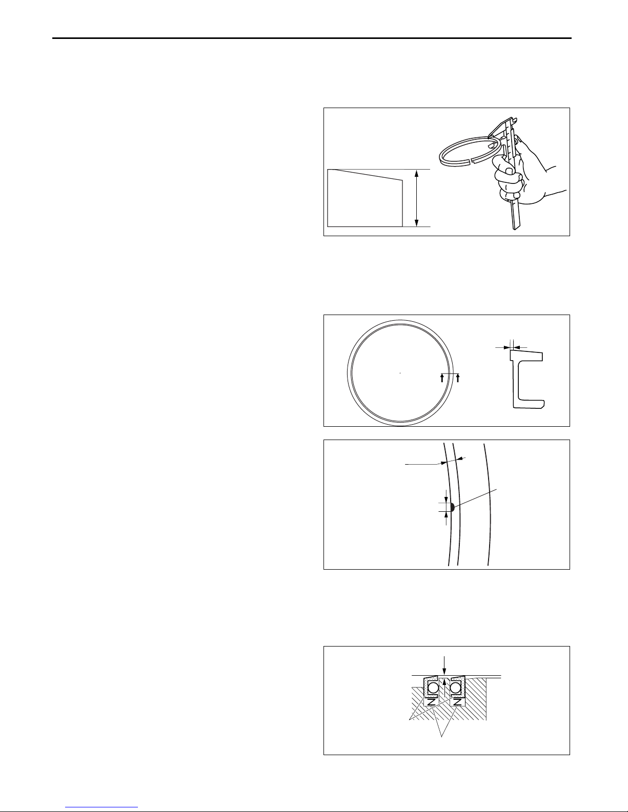
1. Measure the cut-off seal height using a vernier
caliper.
• If it is less than the minimum specification,
replace the cut-off seal.
Caution
• Measure the cut-off seal height around
the complete perimeter.
Standard height
3.95 mm {0.1555 in}
Minimum height
3.8 mm {0.15 in}
End Of Sie
OIL SEAL INSPECTION
1. Measure the following two items using a vernier caliper.
• If either of the items exceeds the maximum specification, replace the oil seal.
(1) Width of area that contacts the oil seal lip.
CHU011011B10E05
CHU011011B10E06
BHJ0110E042
Caution
• Measure the contact width around the
complete perimeter.
Maximum contact width
0.5 mm {0.02 in}
(2) Circumferential width of any damage along
the lip.
Maximum circumferential width of the oil seal
lip
2.5 mm {0.098 in} or 10 nicks or more
End Of Sie
SPRING INSPECTION
Oil Seal Spring
1. Assemble the oil seal springs into the rotor.
2. Assemble the O-rings into the oil seals.
3. Assemble the oil seals into the rotor.
4. Measure the oil seal projection using a vernier
caliper.
• If it is less than the minimum specification,
replace the oil seal spring.
LIP
2.5 mm {0.098 in}
A
A
SEC. A-A
BHJ0110E043
NICK
CHU0110E012
CHU011011B10E07
Minimum projection
0.5 mm {0.02 in}
01–10–18
OIL SEAL
OIL SEAL SPRING
CHU0110E013
Page 36
Engine Workshop Manual 13B-MSP (Multi Side Port) (1773–1U–03C)
MECHANICAL
Cut-off Seal Spring
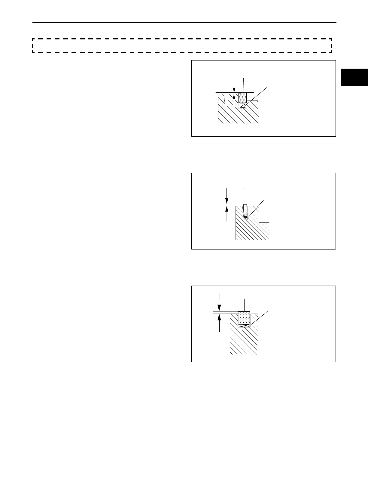
1. Assemble the cut-off seal spring into the rotor.
2. Referring to the cut-off seal inspection procedure, verify that the height of the cut-off seal is at the minimum
specification or more. (See 01–10–18 CUT-OFF SEAL INSPECTION.)
3. Assemble the cut-off seal into the rotor.
4. Measure the cut-off seal projection using a
vernier caliper.
• If it is less than the minimum specification,
replace the cut-off seal spring.
Minimum projection
0.5 mm {0.02 in}
Side Seal Spring
1. Assemble the side seal spring into the rotor.
2. Assemble the side seal into the rotor.
3. Measure the side seal projection using a vernier
caliper.
• If it is less than the minimum specification,
replace the side seal spring.
CUT-OFF SEAL
CUT-OFF SEAL SPRING
CHU0110E041
SIDE SEAL
SIDE SEAL SPRING
01–10
Minimum projection
0.5 mm {0.02 in}
Corner Seal Spring
1. Assemble the corner seal spring into the rotor.
2. Assemble the corner seal into the rotor.
3. Measure the corner seal projection using a
vernier caliper.
• If it is less than the minimum specification,
replace the corner seal spring.
Minimum projection
0.5 mm {0.02 in}
Apex Seal Spring
CHU0110E015
CORNER SEAL
CORNER SEAL SPRING
CHU0110E016
Note
• Inspect the long apex seal spring.
Revised 6/2008 (Ref. No. R108/08)
01–10–19
Page 37
Engine Workshop Manual 13B-MSP (Multi Side Port) (1773–1U–03C)
MECHANICAL
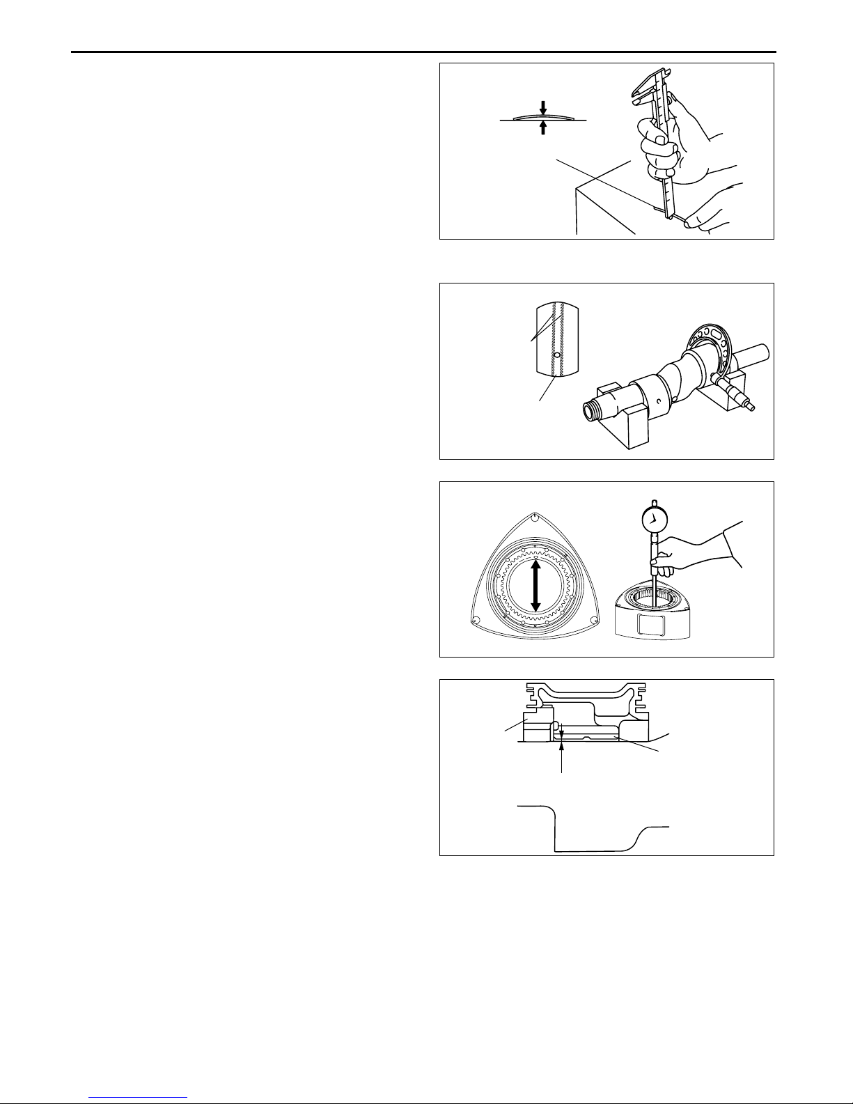
1. Measure the height of the apex seal spring using
a vernier caliper with the spring placed on a
surface plate.
• If it is less than the minimum specification,
replace the apex seal spring.
Standard height
5.4 mm {0.213 in}
Minimum height
3.5 mm {0.148 in}
End Of Sie
ROTOR BEARING OIL CLEARANCE INSPECTION
1. Measure the outer diameter of the rotor journal
using a micrometer.
Caution
• Measure the rotor journal at a point
slightly off-center since the center
section is raised. Do not measure at the
center because it does not contact the
rotor bearing.
2. Measure the inner diameter of the rotor bearing
using a cylinder gauge.
APEX SEAL SPRING (LONG)
CHU0110E064
CHU011011B10E08
ROTOR JOURNAL (SIDE VIEW)
MEASUREMENT
LOCATION
NOT MEASURED
CHU0110E071
3. Calculate the rotor bearing oil clearance from the
rotor journal outer diameter and the rotor bearing
inner diameter.
Rotor bearing oil clearance = (rotor bearing
inner diameter) – (rotor journal outer
diameter)
• If it exceeds the minimum specification,
replace the rotor bearing. (See 01–10–21
ROTOR BEARING REPLACEMENT.)
• If not within the specification, even with the
rotor bearing replaced, replace the eccentric
shaft.
Standard rotor bearing oil clearance
0.06—0.08 mm {0.0024—0.0030 in}
Maximum rotor bearing oil clearance
0.1 mm {0.0039 in}
End Of Sie
BHJ0110E062
ROTOR
ROTOR BEARING
ECCENTRIC SHAFT
CHU0110E017
01–10–20
Page 38
Engine Workshop Manual 13B-MSP (Multi Side Port) (1773–1U–03C)
MECHANICAL
ROTOR BEARING REPLACEMENT
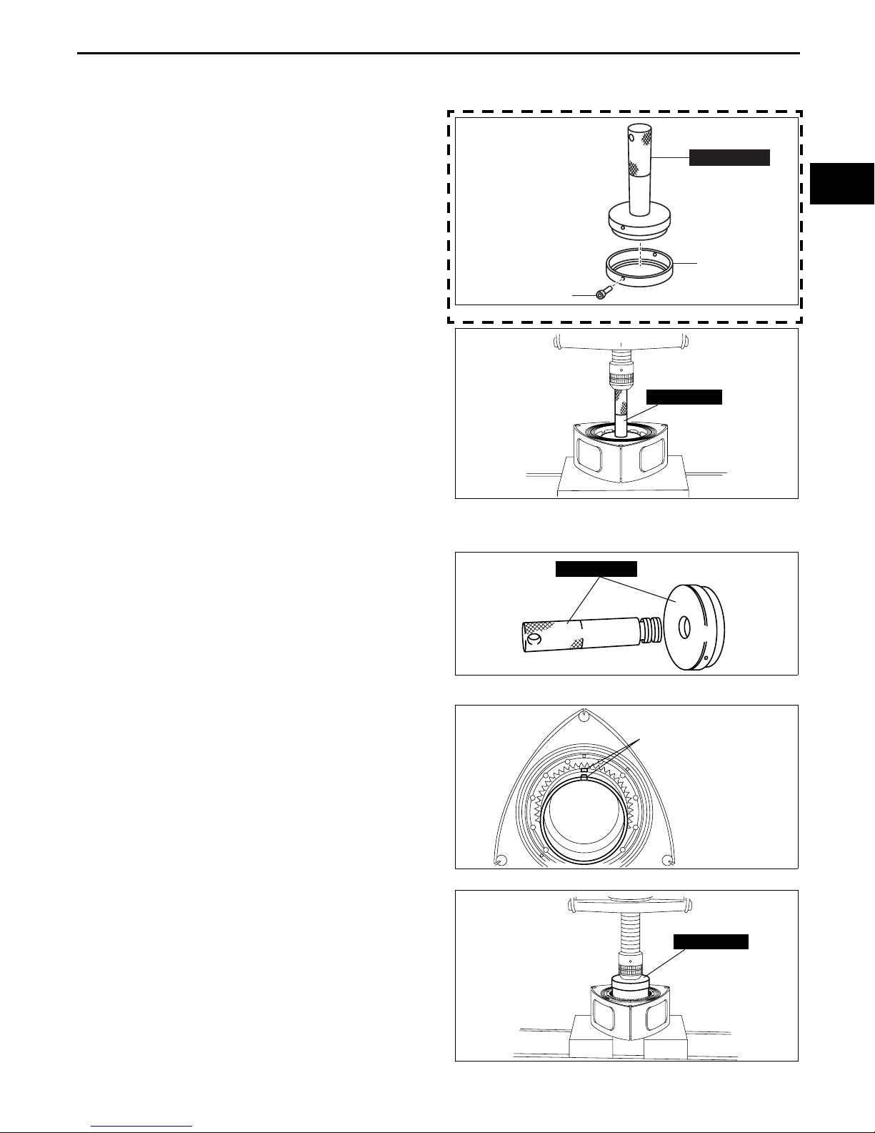
Removal
1. Set the rotor with the internal gear at the bottom.
2. Remove the adapter ring and the securing screw
from the SST.
3. Remove the rotor bearing using the SST.
CHU011011B10E09
49 0813 240
01–10
ADAPTER RING
SECURING SCREW
BHJ0110F004
49 0813 240
Installation
1. Remove the SST handle.
2. Temporarily assemble so that the rotor bearing
tab and the rotor notch are aligned after pressing
in the rotor bearing and rotor.
3. Set the temporarily assembled rotor bearing and
rotor on a hydraulic press.
4. Press in the rotor bearing using the SST.
End Of Sie
BHJ0110E063
49 0813 240
BHJ0110E064
ALIGN TAB AND NOTCH
CHU0110E018
Revised 6/2008 (Ref. No. R108/08)
49 0813 240
BHJ0110E066
01–10–21
Page 39
Engine Workshop Manual 13B-MSP (Multi Side Port) (1773–1U–03C)
MECHANICAL
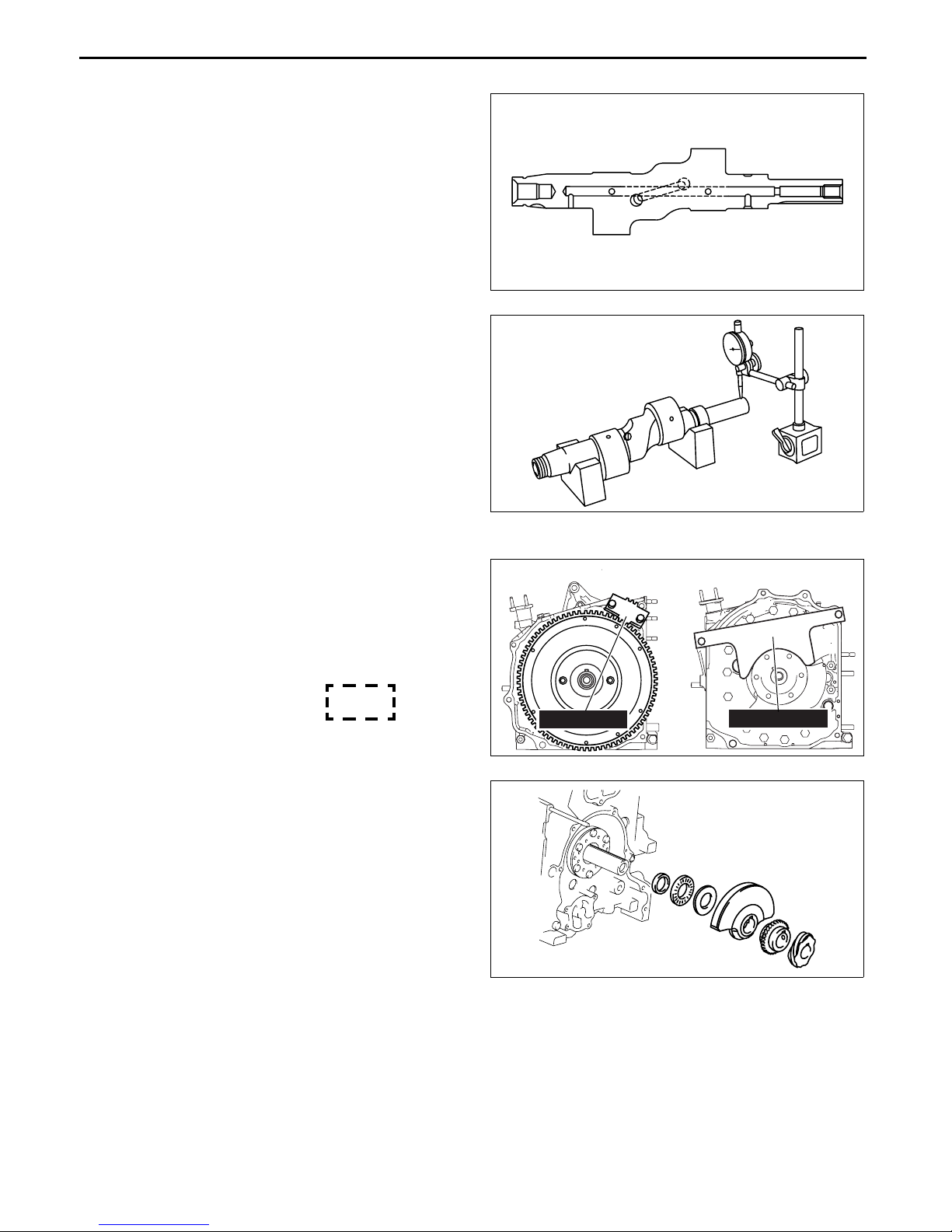
ECCENTRIC SHAFT INSPECTION
1. Inspect for clogging in the oil passage.
• If there is any clogging, remove it with a
needle or similar device and clean with
compressed air.
2. After setting the eccentric shaft main journal on Vblocks and a surface plate, measure the runout at
the end of the eccentric shaft using a dial gauge.
• If it exceeds the maximum specification,
replace the eccentric shaft.
Standard runout
0.02 mm {0.0008 in}
Maximum runout
0.06 mm {0.0024 in}
End Of Sie
ECCENTRIC SHAFT END PLAY INSPECTION
1. Lock the flywheel (MT) or counterweight (AT)
against rotation using the SST.
2. Assemble the parts in the following order:
(1) Spacer
(2) Needle bearing
(3) Thrust plate
(4) Balance weight
(5) Oil pump drive gear
(6) Metering oil pump drive gear (Type A)
MT
49 F011 101
CHU011011D01E01
BHJ0110E050
BHJ0110E051
CHU011011D01E02
AT
49 1881 055A
Caution
• When assembling the spacer, do not
allow the spacer to be caught in the
needle bearing in the plate.
01–10–22
BHJ0110E007
BHJ0110E052
Revised 6/2008 (Ref. No. R108/08)
Page 40
Engine Workshop Manual 13B-MSP (Multi Side Port) (1773–1U–03C)
MECHANICAL
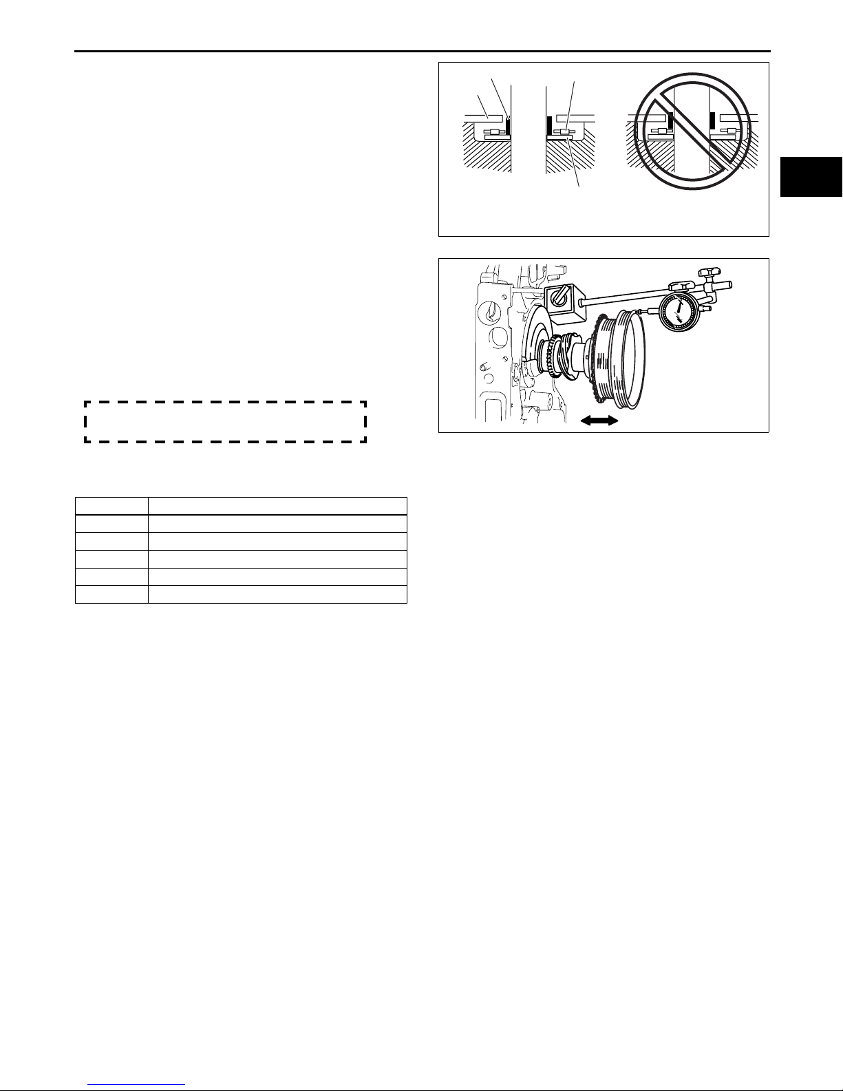
3. Assemble the eccentric shaft pulley, eccentric
shaft position plate, pulley boss component apply
engine oil to the pulley lockbolt threads, and then
tighten.
Tightening torque
300—340 N·m {30.6—34.6 kgf·m, 222—250
ft·lbf}
4. Remove the SST.
5. Measure the end play of the eccentric shaft using
a dial gauge.
• If not within the specification, replace the
spacer with one that is thicker than the
currently assembled one. If it exceeds the
specification, replace with a thinner spacer.
Standard end play
0.04—0.09 mm {0.0016—0.0035 in}
SPACER
PLATE
NEEDLE BEARING
THRUST PLATE
GOOD
01–10
NO GOOD
CHU0110E019
BHJ0110E054
Spacer types
(mm {in})
Marking Dimension
A 7.985 {0.3144}
B 8.005 {0.3152}
C 8.025 {0.3159}
D 8.045 {0.3167}
E 8.065 {0.3175}
Note
• If the end play is not within the specification even after replacing with an A-marked spacer, adjust by
grinding it and reuse.
End Of Sie
Revised 6/2008 (Ref. No. R108/08)
01–10–23
Page 41
Engine Workshop Manual 13B-MSP (Multi Side Port) (1773–1U–03C)
GREASE
MECHANICAL
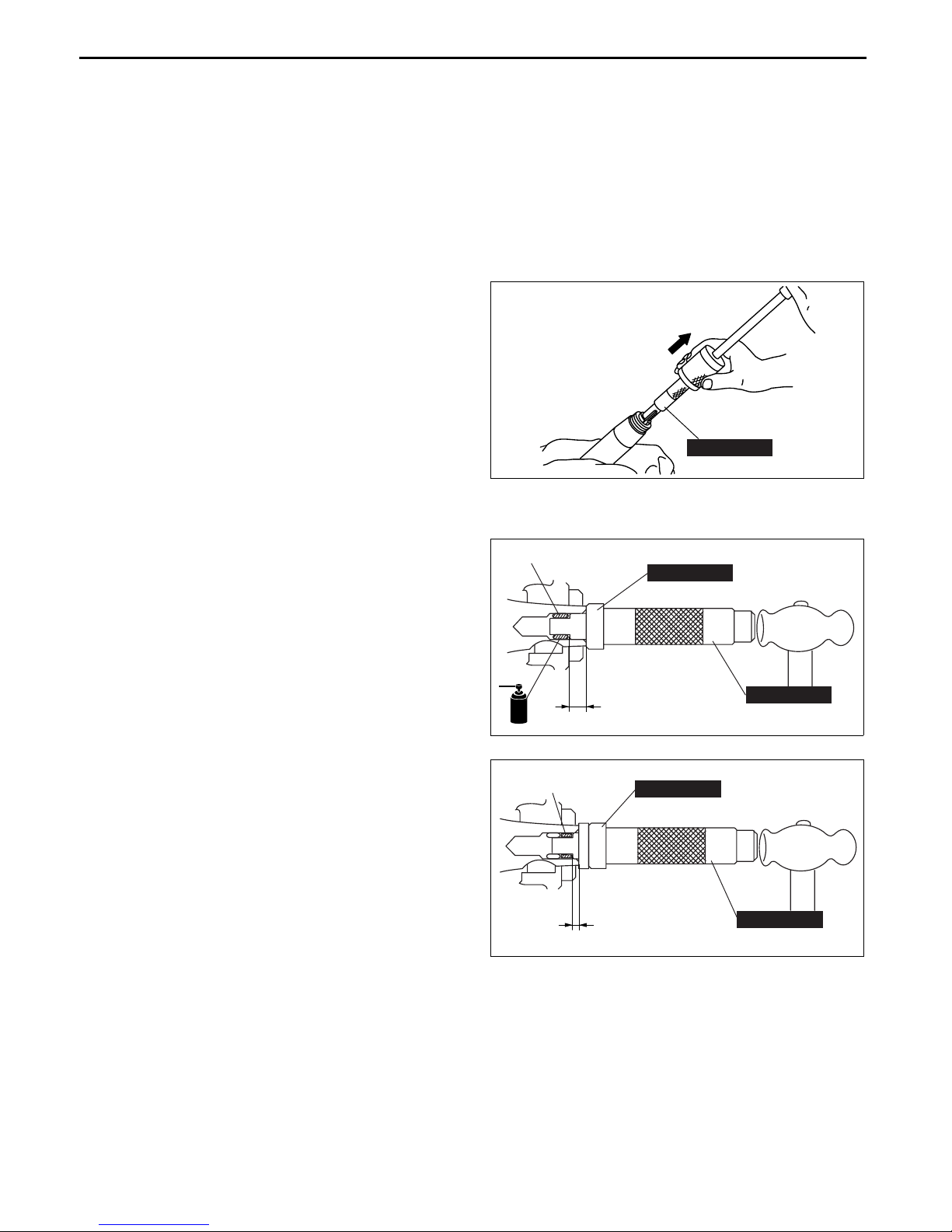
PILOT BEARING INSPECTION/REPLACEMENT [MT]
Inspection
Caution
• Inspect the pilot bearing when it is installed to the eccentric shaft.
1. Before removing the pilot bearing, inspect it for damage, wear, and proper rotation.
• If there is any malfunction, replace the pilot bearing.
Replacement
Removal
1. Fix the eccentric shaft on a vice.
2. Remove the pilot bearing and the oil seal together
using the SST.
CHU011011D01E03
49 1285 071
BHJ0110E070
Installation
1. Install a new pilot bearing using the SSTs.
2. Apply grease to the pilot bearing.
3. Install a new oil seal using the SSTs.
End Of Sie
PILOT BEARING
49 F011 1A1
11.5—12.25 mm {0.4528—0.4822 in}
OIL SEAL
5.5—6.3 mm {0.217—0.248 in}
49 F011 1A1
49 G030 797
CHU0110E020
49 G030 797
CHU0110E021
01–10–24
Page 42
Engine Workshop Manual 13B-MSP (Multi Side Port) (1773–1U–03C)
MECHANICAL
ECCENTRIC SHAFT BYPASS VALVE
Warning
• Engine oil temperature will increase during the inspection and become very dangerous. Be careful
not to burn yourself during the inspection.
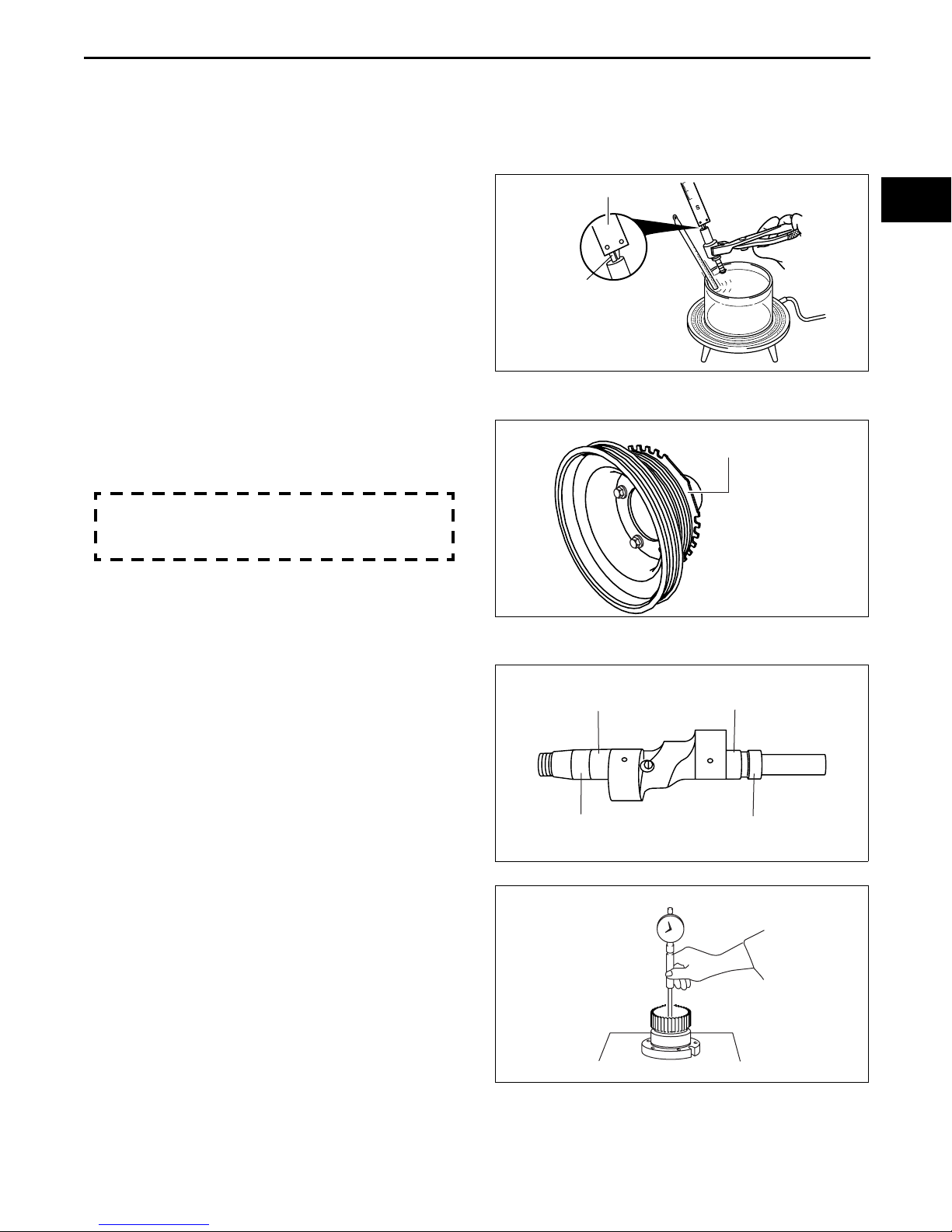
1. Put the eccentric shaft bypass valve in a
container filled with engine oil.
VERNIER CALIPER
2. Heat the container and verify that the projection
protrudes more than the minimum specification
when the engine oil temperature is 60 °C {140
°F}.
• If it is less than the minimum specification,
replace the eccentric shaft bypass valve.
PROJECTION PART
Minimum projection
6 mm {0.24 in}
End Of Sie
ECCENTRIC SHAFT POSITION PLATE INSPECTION
1. Visually inspect the eccentric shaft position plate
for damage and erosion.
• If there is any malfunction, replace the
eccentric shaft position plate.
Eccentric shaft pulley tightening torque
14.2—17.2 N·m {1.45—1.75 kgf·m, 10.5—12.6
ft·lbf}
ECCENTRIC SHAFT
POSITION PLATE
CHU011011D01E04
01–10
CHU0110E057
CHU011011D01E05
End Of Sie
MAIN BEARING OIL CLEARANCE INSPECTION
1. Using a micrometer, measure the outer diameters
of the inside main journal.
2. Using a cylinder bore gauge, measure the inner
diameter of the stationary gear main bearing.
INSIDE
OUTSIDE
BHJ0110E106
CHU011010E00E01
INSIDE
OUTSIDE
CHU0110E022
Revised 6/2008 (Ref. No. R108/08)
BHJ0110E056
01–10–25
Page 43
Engine Workshop Manual 13B-MSP (Multi Side Port) (1773–1U–03C)
MECHANICAL
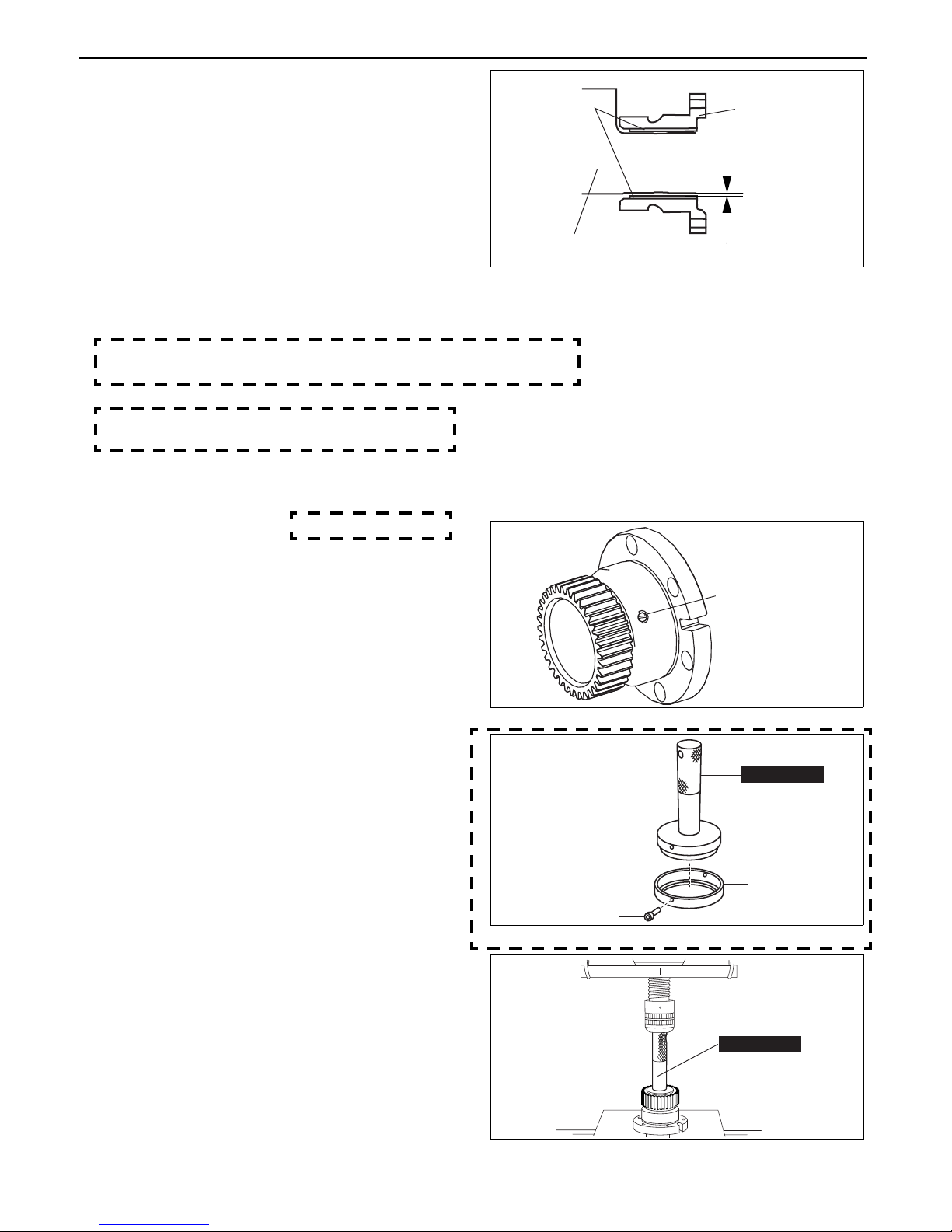
3. Calculate the main bearing oil clearance from the
main journal outer diameter and the main bearing
inner diameter.
Main bearing oil clearance = (main bearing
inner diameter) – (main journal outer
diameter)
• If it exceeds the maximum specification,
replace the main bearing. (See 01–10–26
MAIN BEARING REPLACEMENT.)
— If the clearance is not within the
specification after replacing the main
bearing, replace the eccentric shaft.
Standard main bearing oil clearance
Without stopper screw: 0.045—0.085 mm {0.0018—0.0033 in}
With stopper screw: 0.055—0.075 mm {0.0022—0.0029 in}
Maximum main bearing oil clearance
Without stopper screw: 0.1 mm {0.0039 in}
With stopper screw: 0.1 mm {0.0039 in}
End Of Sie
MAIN BEARING REPLACEMENT
Removal
1. Remove the stopper screw. (With stopper screw)
MAIN BEARING
ECCENTRIC SHAFT
STATIONARY GEAR
CHU0110E023
CHU011010E00E02
2. Remove the adapter ring and the securing screw
from the SST.
3. Set the stationary gear to the hydraulic press so
that the gear faces upward.
4. Remove the main bearing using the SST.
STOPPER SCREW
CHU0110E042
49 0813 235
ADAPTER RING
SECURING SCREW
BHJ0110F005
49 0813 235
01–10–26
BHJ0110E057
Revised 6/2008 (Ref. No. R108/08)
Page 44
Engine Workshop Manual 13B-MSP (Multi Side Port) (1773–1U–03C)
MECHANICAL
Installation
Without stopper screw
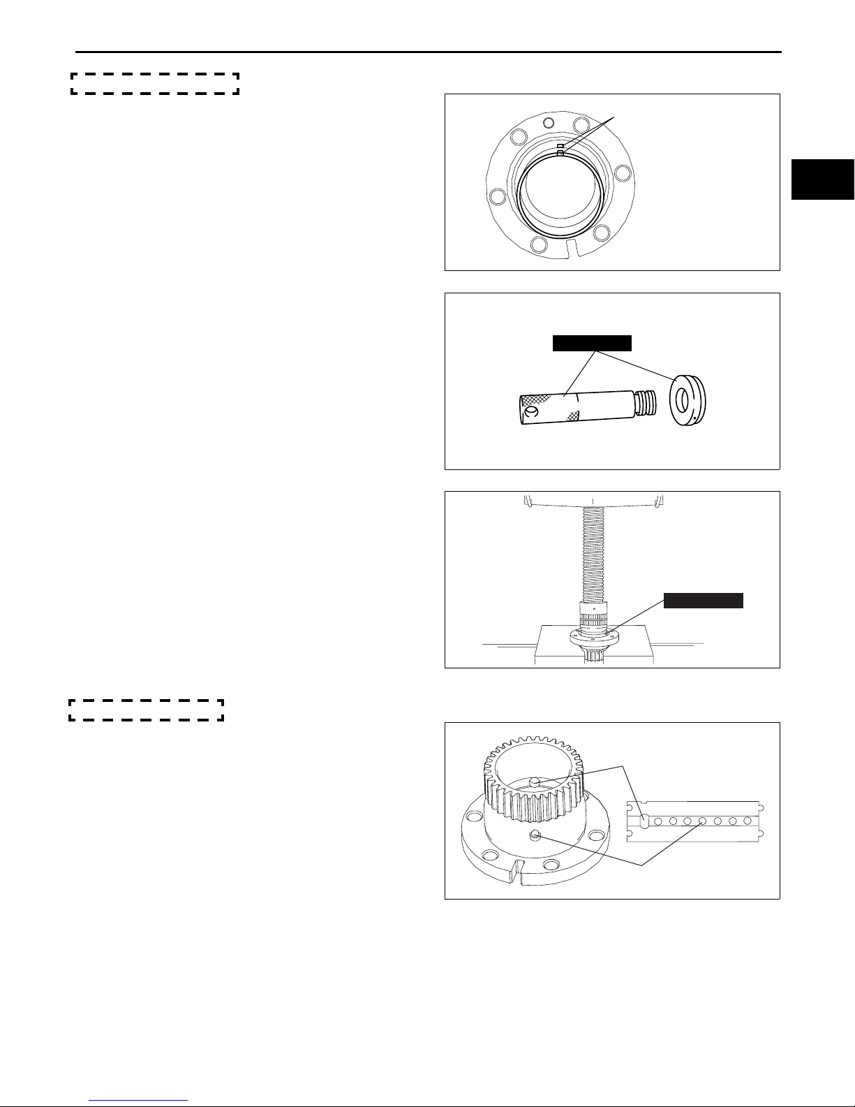
1. Temporarily assemble the stationary gear and the
main bearing so that the main bearing tab and
notch are aligned after pressing in the main
bearing and stationary gear.
2. Remove the SST handle.
ALIGN TAB AND NOTCH
01–10
CHU0110E043
49 0813 235
3. Position the gear of the stationary gear
downward, and install the main bearing by
pressing it with the SST.
Caution
• Press the main bearing in so that the top
of the main bearing is flush with the top
of the stationary gear flange.
With stopper screw
1. Temporarily assemble the stationary gear and the
main bearing so that the main bearing screw hole
and the stationary gear screw hole are aligned
after pressing in the main bearing and rotor.
BHJ0110E059
49 0813 235
BHJ0110E060
OIL HOLE
STOPPER SCREW HOLE
Revised 6/2008 (Ref. No. R108/08)
CHU0110E044
01–10–27
Page 45
Engine Workshop Manual 13B-MSP (Multi Side Port) (1773–1U–03C)
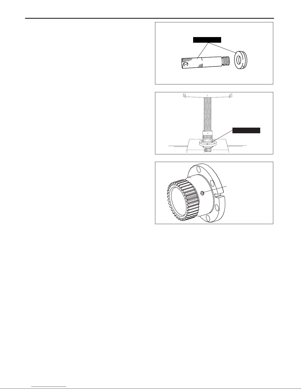
2. Remove the SST handle.
3. Position the gear of the stationary gear
downward, and install the main bearing using the
SST.
Caution
• Press the main bearing in so that the top
of the main bearing is flush with the top
of the stationary gear flange.
MECHANICAL
49 0813 235
BHJ0110E059
49 0813 235
4. Apply thread-locking compound to the stopper
screw and install.
Tightening torque
3.2—4.7 N·m
{33—47 kgf·cm, 29—41 in·lbf}
End Of Sie
BHJ0110E060
STOPPER SCREW
CHU0110E042
01–10–28
Page 46
Engine Workshop Manual 13B-MSP (Multi Side Port) (1773–1U–03C)
MECHANICAL
OIL PUMP INSPECTION
Typ e A
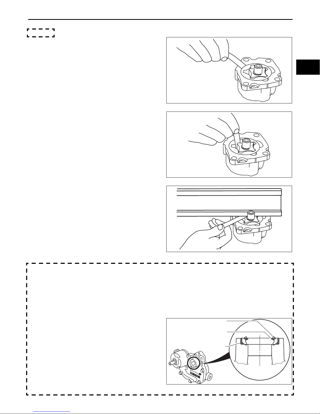
1. Measure the body clearance between the outer
rotor and the body using a feeler gauge.
• If it exceeds the maximum specification,
replace the oil pump.
Standard body clearance
0.20—0.25 mm {0.0079—0.0098 in}
Maximum body clearance
0.3 mm {0.0118 in}
2. Measure the tip clearance between the inner rotor
and the outer rotor using a feeler gauge.
• If it exceeds the maximum specification,
replace the oil pump.
Standard tip clearance
0.03—0.12 mm {0.0012—0.0047 in}
Maximum tip clearance
0.15 mm {0.0059 in}
CHU011014100E01
01–10
BHJ0110E067
3. Measure the side clearance between the rotor
and the side housing using a straight edge and a
feeler gauge.
• If it exceeds the maximum specification,
replace the oil pump.
Standard side clearance
0.03—0.125 mm {0.0012—0.0049 in}
Maximum side clearance
0.15 mm {0.0059 in}
Typ e B
Note
• The oil pump cannot be disassembled because it is a precision unit. If a malfunction occurs, replace the
oil pump component as a single unit.
1. Visually inspect the oil pump gasket.
• Replace the oil pump component if the condition corresponds to any one of the following:
— The lip is damaged.
— The lip and the metallic outer ring are at
the same level.
End Of Sie
SHAPE OF NEW GASKET LIP
SHAPE OF DETERIORATED
GASKET LIP (LEVEL WITH
METALLIC OUTER RING)
BHJ0110E068
BHJ0110E069
Revised 6/2008 (Ref. No. R108/08)
METALLIC OUTER RING
GHE0110E002
01–10–29
Page 47
Engine Workshop Manual 13B-MSP (Multi Side Port) (1773–1U–03C)
P
P
MECHANICAL
ROTOR ASSEMBLY
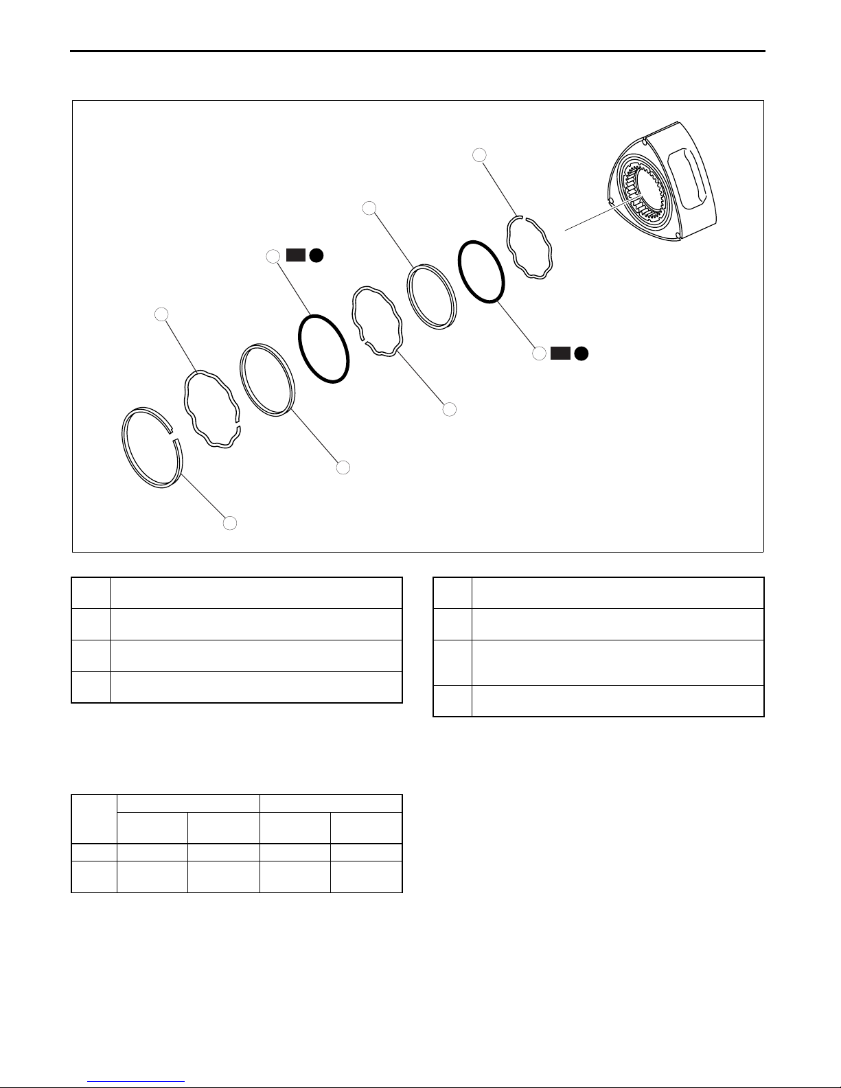
1. Assemble in the order indicated in the table.
R
5
7
CHU011002000E08
1
3
R
2
4
6
8
.
1 Inner oil seal spring
(See 01–10–30 Oil Seal Spring Assembly Note.)
2 Inner O-ring (small radius)
(See 01–10–31 O-Ring Assembly Note.)
3 Inner oil seal
(See 01–10–32 Oil Seal Assembly Note.)
4 Outer oil seal spring
(See 01–10–30 Oil Seal Spring Assembly Note.)
5 Outer O-ring (large radius)
6 Outer oil seal
7 Cut-off seal spring
8 Cut-off seal
Oil Seal Spring Assembly Note
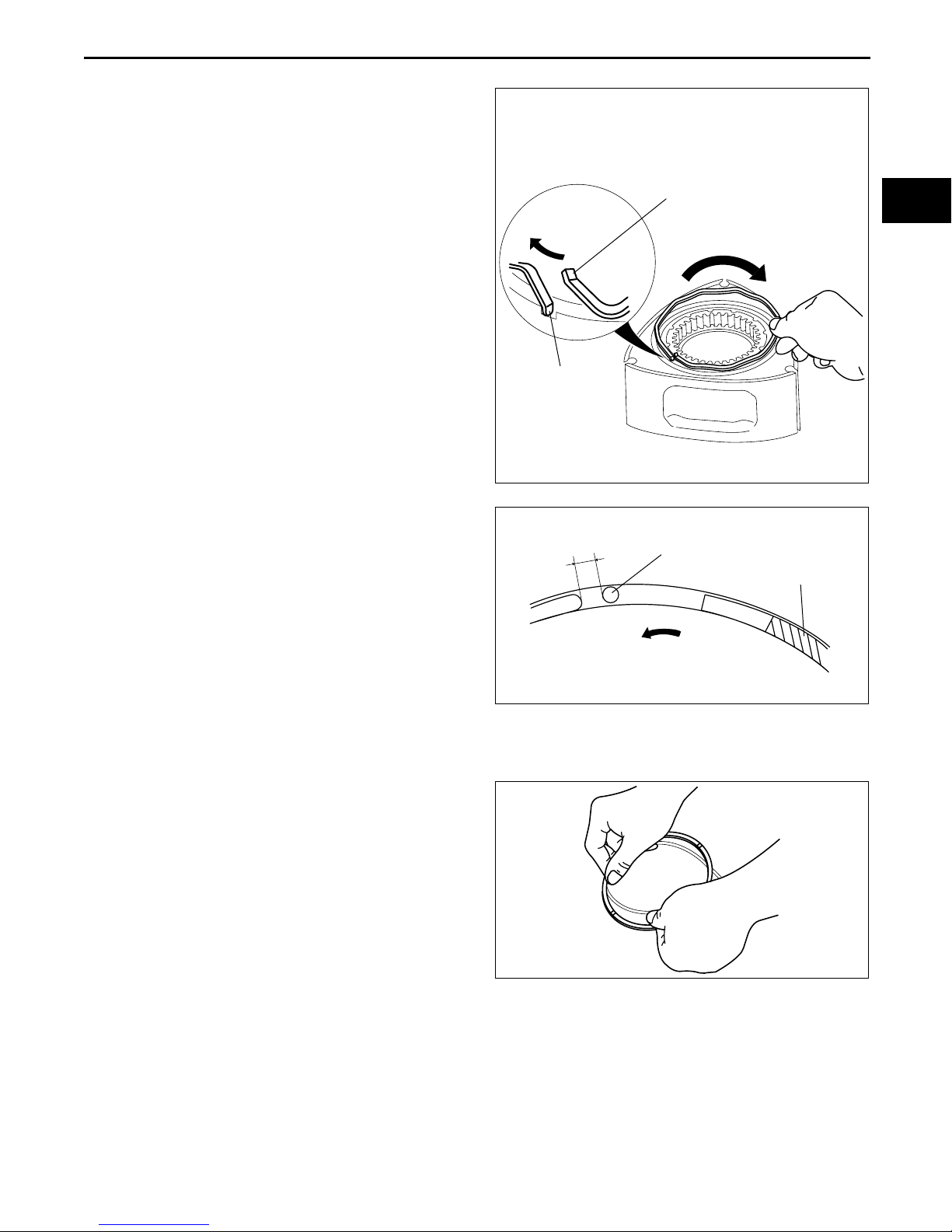
1. Assemble the oil seal spring with the identification color upward.
Spring Identification Color
Front rotor Rear rotor
Rotor
Inner White Blue White Blue
Outer
Engine
front side
White +
pink
Engine
rear side
Blue + pink
Engine
front side
White +
pink
Engine
rear side
Blue + pink
BHJ0110E074
(See 01–10–31 O-Ring Assembly Note.)
(See 01–10–32 Oil Seal Assembly Note.)
(See 01–10–32 Cut-Off Seal Spring Assembly
Note.)
(See 01–10–33 Cut-Off Seal Assembly Note.)
01–10–30
Page 48
MECHANICAL
Caution
•
• It is possible that the identification color
••
may not be visible when reusing the oil
spring. In that case, assemble the
rounded end towards the rotor side and
the squared end upward.
•
• Be careful when assem blin g the oil seal
••
spring of the front and rear rotor since
each spring of the engine front side and
engine rear side are the same.
Note
• Either one of the two rotation lock slots on
the oil seal can be used as a reference.
• Assemble the rounded end within 0—15 mm
{0—0.59 in} away from the oil seal spring
rotation lock.
ENGINE FRONT SIDE AND REAR SIDE
ROTOR
ROTATION
DIRECTION
ROUNDED END
0—15 mm {0—0.59 in}
SQUARED END
01–10
ROTOR
ROTATION
DIRECTION
CHU0110E024
ROTATION LOCK
O-Ring Assembly Note
1. Apply petroleum jelly to a new O-ring.
2. Assemble the O-ring to the oil seal.
Note
• Assemble the thicker O-ring to the inner oil
seal (small radius), and the thinner O-ring to
the outer oil seal (large radius).
IDENTIFICATION COLOR
ROTOR ROTATION DIRECTION
CHU0110E025
BHJ0110E077
01–10–31
Page 49
MECHANICAL
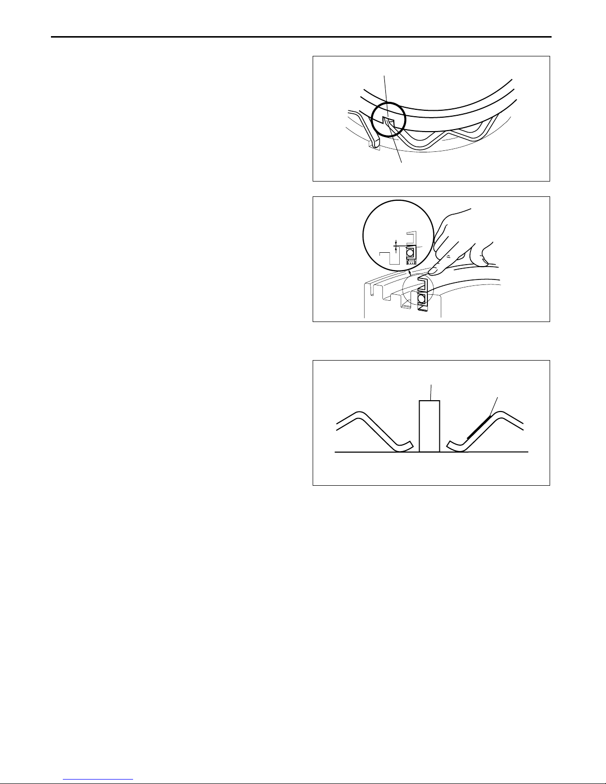
Oil Seal Assembly Note
1. Temporarily install the oil seal with the squared
end of the oil seal spring fit into the slot of the oil
seal.
2. Push in the oil seal using an old oil seal.
3. Verify that the stroke of the oil se al is smooth and
there is no catching by pushing the oil seal with
your hand.
OIL SEAL SLOT
SQUARED END
CHU0110E026
0.5—0.6 mm
{0.020—0.023 in}
OLD OIL SEAL
ROTOR
CHU0110E027
Cut-Off Seal Spring Assembly Note
1. Assemble the cut-off seal spring with the spring
end turned upward.
Note
• When replacing a cut-off seal with a new
one, assemble the seal with the pink surface
facing upward.
ROTATION LOCK PIN
PINK PAINT
ROTOR
CHU0110E028
01–10–32
Page 50
MECHANICAL
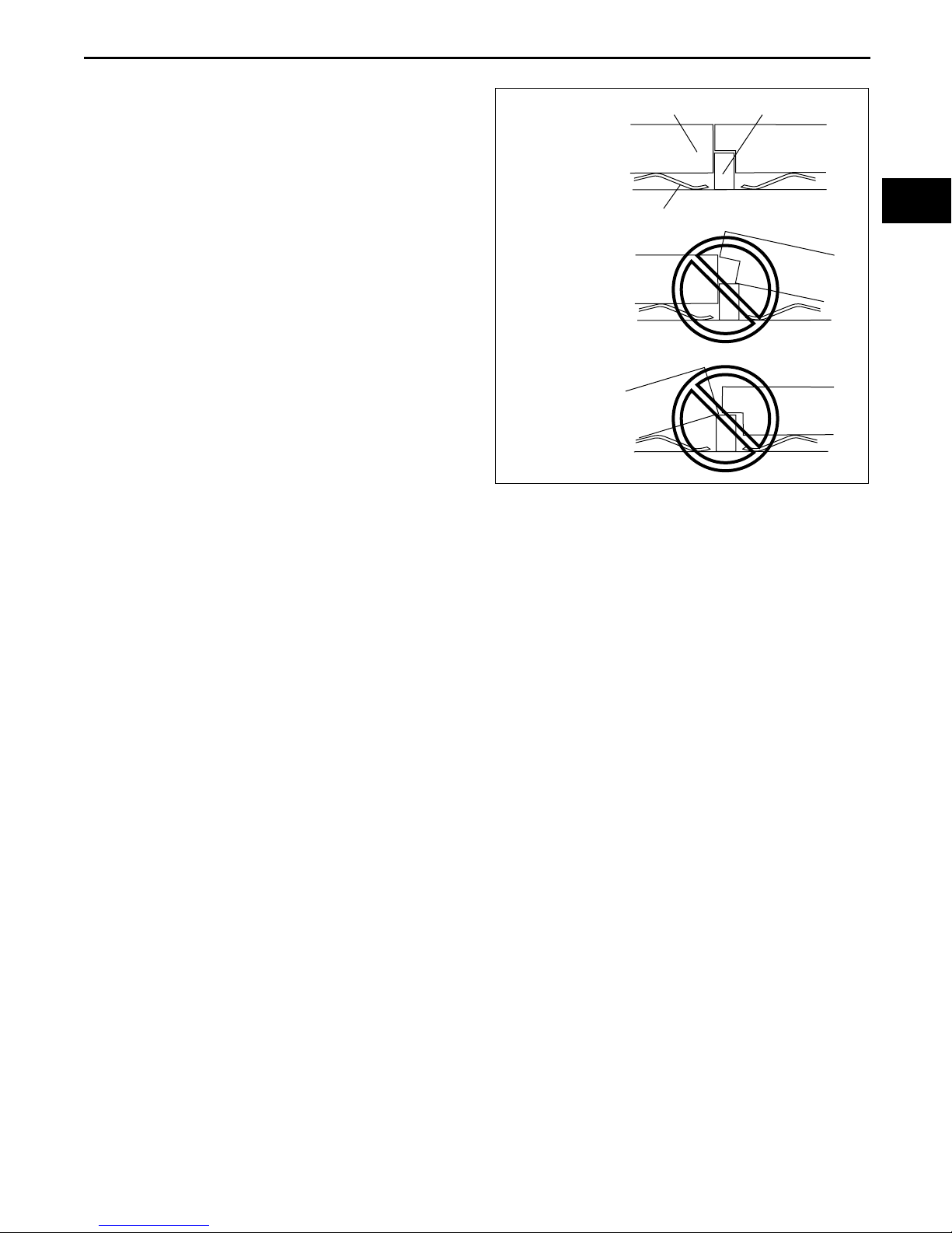
Cut-Off Seal Assembly Note
1. Assemble the cut-off se al so that it does not run
over the rotation lock pin.
End Of Sie
GOOD
CUT-OFF SEAL
ROTATION LOCK PIN
NO GOOD
NO GOOD
ROTOR
CUT-OFF SEAL SPRING
01–10
CHU0110E029
01–10–33
Page 51
MECHANICAL
SEALANT
OIL
SEALANT
SEALANT
SEALANT
OIL
OIL
OIL
OIL
OIL
OIL
OIL
OIL
OIL
OIL
OIL
OIL
OIL
OIL
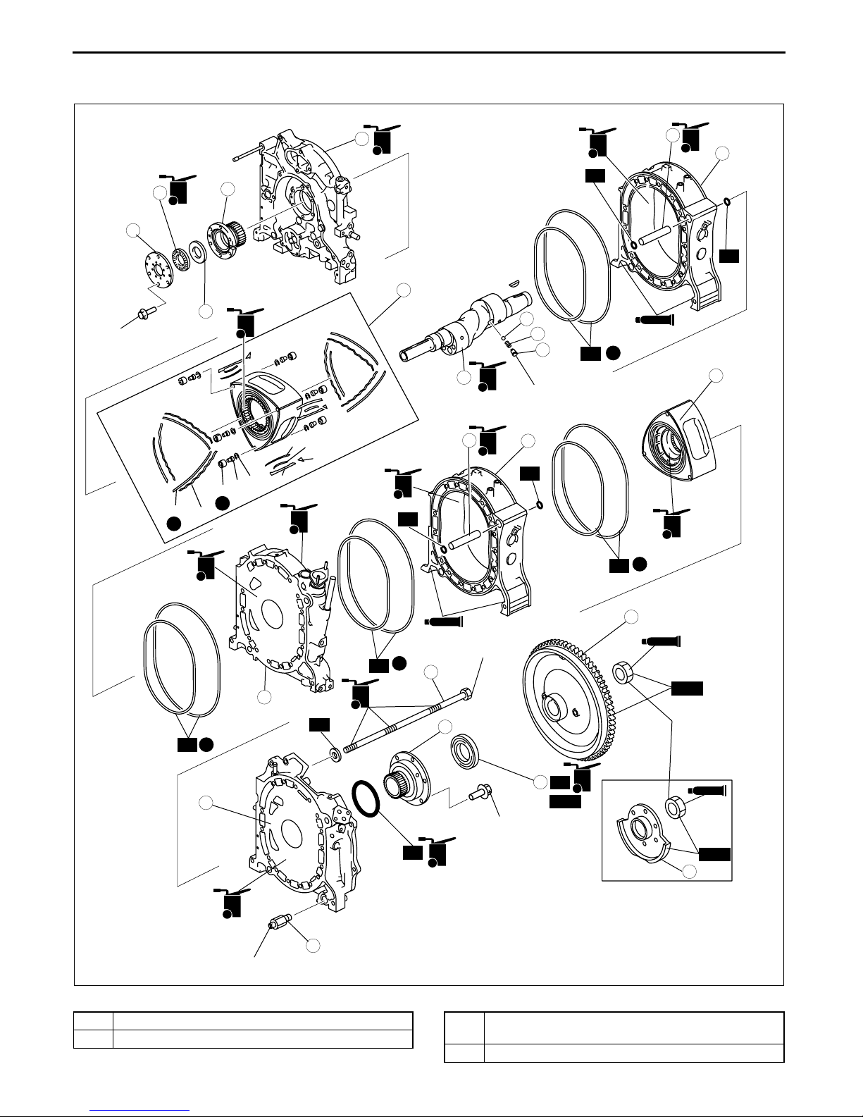
HOUSING ASSEMBLY I
1. Assemble in the order indicated in the table.
OIL
4
2
5
3
15.7—22.5
{1.61—2.29, 11.6—16.5}
A
P
B
OIL
I
H
F
G
E
D
C
P
OIL
CHU011002000E09
OIL
OIL
1
OIL
12
11
R
R
6
7
SEALANT
8
9
OIL
10
OIL
16
OIL
R
3.9—11.7
{40—119 kgf·cm,
35—103 in·lbf}
15
R
R
P
14
OIL
OIL
13
R
OIL
R
R
P
20
SEALANT
31.4—39.2
{3.21—3.99, 23.2—28.9}
P
21
18
15.7—22.5
{1.61—2.29, 11.6—16.5}
OIL
R
19
R
SST
OIL
R
AT
P
22
SEALANT
SST
392—490
{39.8—49.9, 290—361}
SEALANT
SST
22
OIL
17
68.6—78.4 {6.70—7.99, 50.6—57.8}
N·m {kgf·m, ft·lbf}
.
1 Front housing
2 Front stationary gear
01–10–34
CHU0110E052
3 Thrust plate
(See 01–10–35 Thrust Plate Assembly Note.)
4 Needle bearing
Page 52
Engine Workshop Manual 13B-MSP (Multi Side Port) (1773–1U–03C)
MECHANICAL
5Plate
6 Front rotor
A: Side seal
B: Side seal spring
C: Corner seal
D: Corner seal plug
E: Corner seal spring
F: Side piece
G: Apex seal
H: Apex seal spring (short)
I: Apex seal spring (long)
(See 01–10–35 Rotor Assembly Note.)
7 Steel ball
8Spring
9 Oil jet plug
(See 01–10–36 Oil Jet Plug Assembly Note.)
10 Eccentric shaft
11 Front rotor housing
(See 01–10–37 Rotor Housing Assembly Note.)
12 Tubular dowel (front rotor housing side)
Thrust Plate Assembly Note
1. Place the chamfer side facing the stationary gear.
13 Intermediate housing
(See 01–10–38 Intermediate Housing Assembly
Note.)
14 Rear rotor
(See 01–10–35 Rotor Assembly Note.)
15 Rear rotor housing
(See 01–10–37 Rotor Housing Assembly Note.)
16 Tubular dowel (rear rotor housing side)
17 Pressure regulator (Type A)
18 Rear stationary gear
19 Rear oil seal
(See 01–10–39 Rear Oil Seal Assembly Note.)
20 Rear housing
(See 01–10–40 Rear Housing Assembly Note.)
Tension bolt
21
(See 01–10–40 Tension Bolt Assembly Note.)
22 Flywheel (MT), counterweight (AT)
(See 01–10–41 Flywheel (MT), Counterweight (AT)
Assembly Note.)
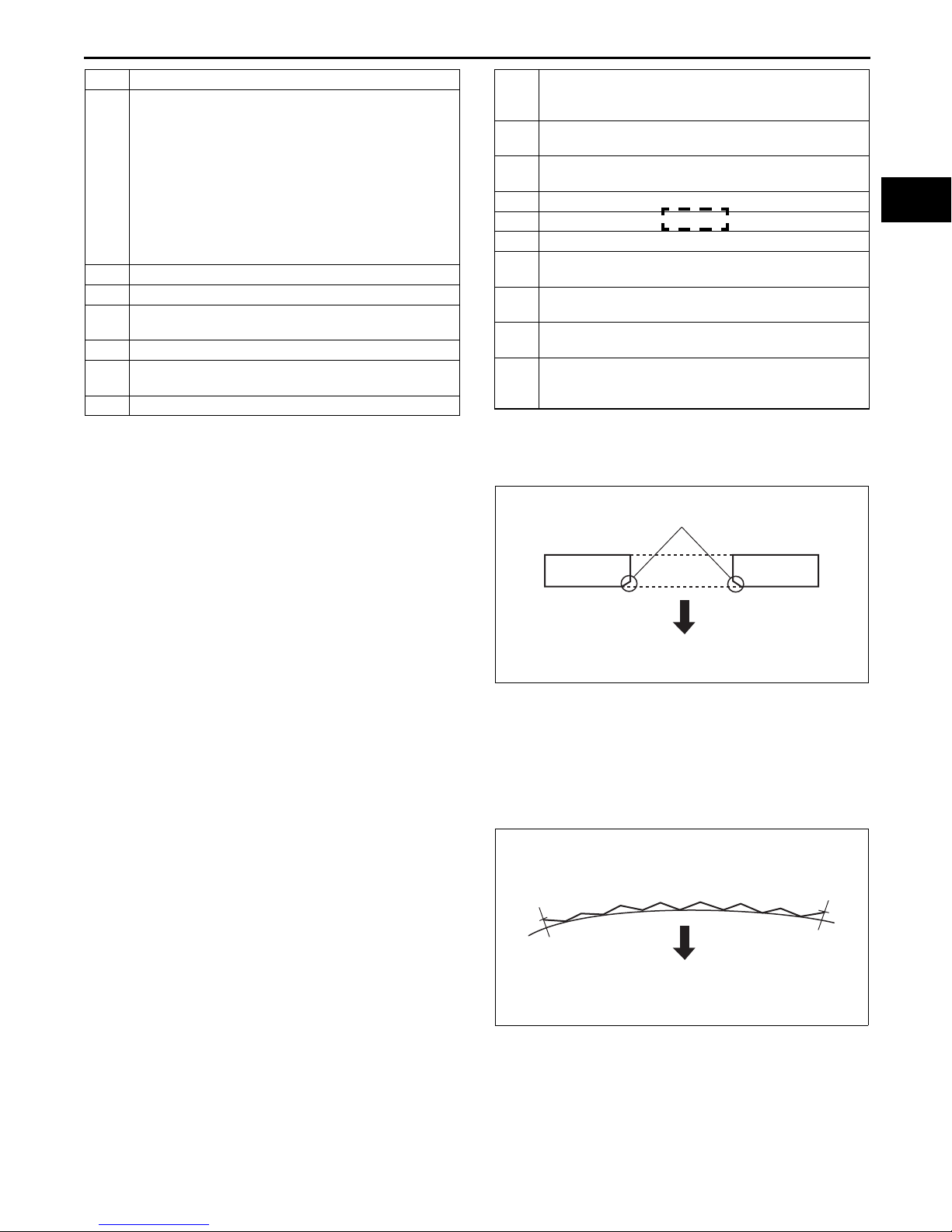
CHAMFER SIDE
01–10
STATIONARY GEAR SIDE
Rotor Assembly Note
Caution
• Assemble only the side seal and corner seal on the engine front side while the rotor is not
assembled.
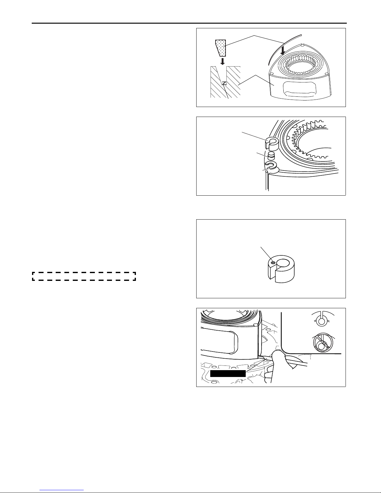
1. Assemble the side seal spring in the direction
shown in the figure.
SIDE SEAL SIDE
ROTOR SIDE
CHU0110E045
CHU0110E046
Revised 6/2008 (Ref. No. R108/08)
01–10–35
Page 53
Engine Workshop Manual 13B-MSP (Multi Side Port) (1773–1U–03C)
MECHANICAL
2. Assemble the side seal spring in the direction
shown in the figure.
3. Apply petroleum jelly between the side seal and
side seal groove.
4. Assemble the corner seal plug to the corner seal.
SIDE SEAL
ROTOR
SIDE SEAL SPRING
CHU0110E047
CORNER SEAL
CORNER SEAL PLUG
CORNER SEAL SPRING
CHU0110E030
Note
• When replacing a corner seal with new one,
assemble the corner seal with the painting
surface facing upward.
5. Assemble the corner seal and corner seal spring
with the notch aligned with the apex seal groove.
6. Apply petroleum jelly between the corner seal and
corner seal groove.
7. Place the rotor in the housing.
8. Insert the SST into the apex seal groove of the
rotor and verify that the apex seal groove of the
corner seal is aligned with the apex seal groove of
the rotor.
9. Assemble the side seal and corner seal for the
engine rear side in the same way as the engine
front side.
S:PINK
L:WHITE
CHU0110E051
GOOD
NO GOOD
49 0813 225A
CHU0110E070
Oil Jet Plug Assembly Note
1. Apply thread locking compound to the seating face of the oil jet plug.
2. Install the oil jet plug.
Tightening torque
3.9—11.7 N·m
{40—119 kgf·cm, 35—103 in·lbf}
01–10–36
Revised 6/2008 (Ref. No. R108/08)
Page 54
Engine Workshop Manual 13B-MSP (Multi Side Port) (1773–1U–03C)
SEALANT
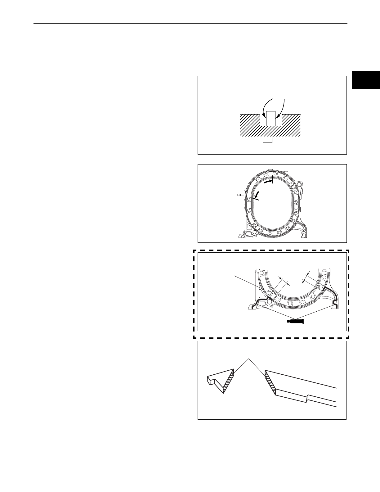
Rotor Housing Assembly Note
Caution
• Assemble the seal rubber without any torsion.
• Do not get oil or grease on the seal rubber.
1. Apply petroleum jelly to a new seal rubber.
2. Assemble the outer seal rubber to the housing
with the white paint in the direction shown in the
figure.
3. Assemble the inner seal rubber to the housing
with the seal rubber joint placed between A—B.
MECHANICAL
01–10
WHITE PAINT
HOUSING
CHU0110E061
4. Apply the silicone sealant to the position indicated
in the figure.
Bead thickness
2.5—6.5 mm {0.099—0.255 in}
5. Apply thread locking compound to the attaching
surface of the apex seal and the side piece and
affix them.
SEAL RUBBER
GROOVE
ATTACHING SURFACE
A
B
CHU0110E062
8—12 mm
{0.32—0.47 in}
CHU0110E033
Caution
• After adhesion, make sure that there is
no gap between the apex seal and side
piece.
Revised 6/2008 (Ref. No. R108/08)
CHU0110E059
01–10–37
Page 55
Engine Workshop Manual 13B-MSP (Multi Side Port) (1773–1U–03C)
MECHANICAL
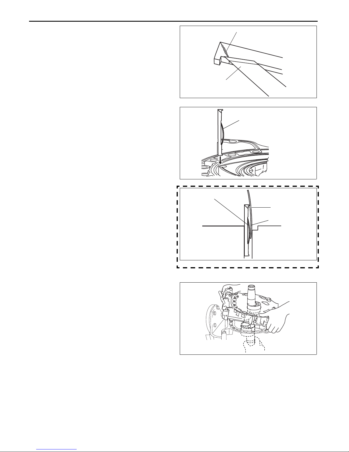
• If adhesive protrudes, remove with a
razor.
Note
• When using a new apex seal, the procedure
above is not needed.
6. Assemble the apex seal and apex seal spring
(short) together with the side piece to the engine
rear side.
7. Assemble the apex seal spring (long) while
pressing the apex seal spring (short).
ADHESIVE
RAZOR
CHU0110E069
APEX SEAL SPRING(SHORT)
CHU0110E063
APEX SEAL SPRING (SHORT)
Caution
• Assemble the apex seal spring until it
catches the spring stopper of the side
piece.
Intermediate Housing Assembly Note
1. Assemble the intermediate housing with the
support of an assistant pushing the eccentric
shaft up approx. 3 cm {1.18 in}.
ROTOR HOUSING
SPRING STOPPER
APEX SEAL SPRING (LONG)
ROTOR
CHU0110E034
BHJ0110E023
01–10–38
Revised 6/2008 (Ref. No. R108/08)
Page 56
MECHANICAL
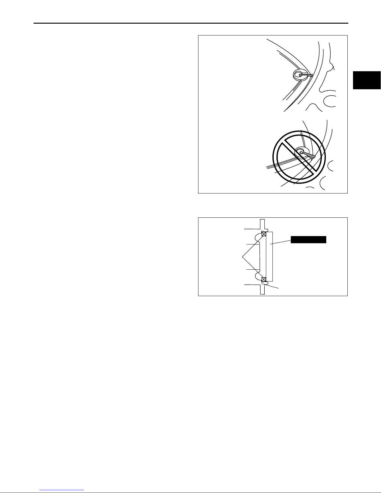
Caution
•
• Do not allow the side piece to be caught
••
between the rotor housing and
intermediate housing.
Rear Oil Seal Assembly Note
1. Assemble the oil seal using the SST.
Caution
•
• Insert the rear oil seal until it is reaches
••
to the seating face.
GOOD
NO GOOD
OIL SEAL
01–10
CHU0110E060
49 J027 001
STATIONARY GEAR
CHU0110E035
01–10–39
Page 57
MECHANICAL
Rear Housing Assembly Note
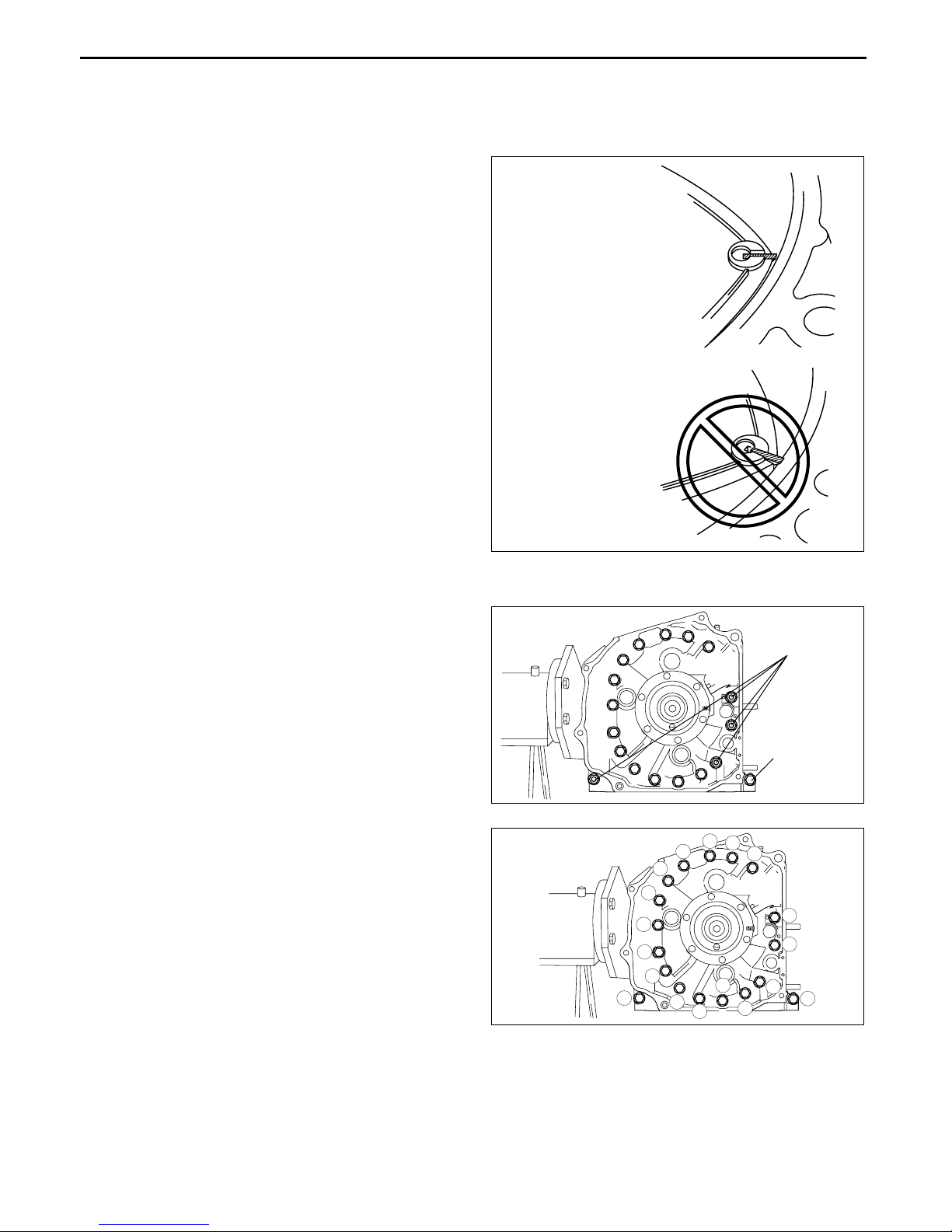
1. Assemble the rear housing with the rear s tationary gear and the internal gear of the rotor engaged.
Caution
•
• Do not allow the side piece to be caught between the rotor housing and rear housing.
••
GOOD
NO GOOD
Tension Bolt Assembly Note
1. Apply engine oil to the tensi on bolt threads and
assemble to the housing with a new seal washer.
Caution
•
• Assemble a tension bolt which has a seal
••
washer with the rubber projection facing
the housing side.
2. Tighten the tension bolts in the order indicated in
the figure in 23 passes.
Tightening torque
31.4—39.2 N·m
{3.21—3.99 kgf·m, 23.2—28.9 ft·lbf}
17
CHU0110E060
INDENTED BOLT
HEAD
WITHOUT SEAL
WASHER
CHU0110E036
15
16
14
11
10
7
3
2
6
18
BHJ0110E094
13
9
5
1
4
8
12
01–10–40
Page 58
Engine Workshop Manual 13B-MSP (Multi Side Port) (1773–1U–03C)
MECHANICAL
Flywheel (MT), Counterweight (AT) Assembly Note
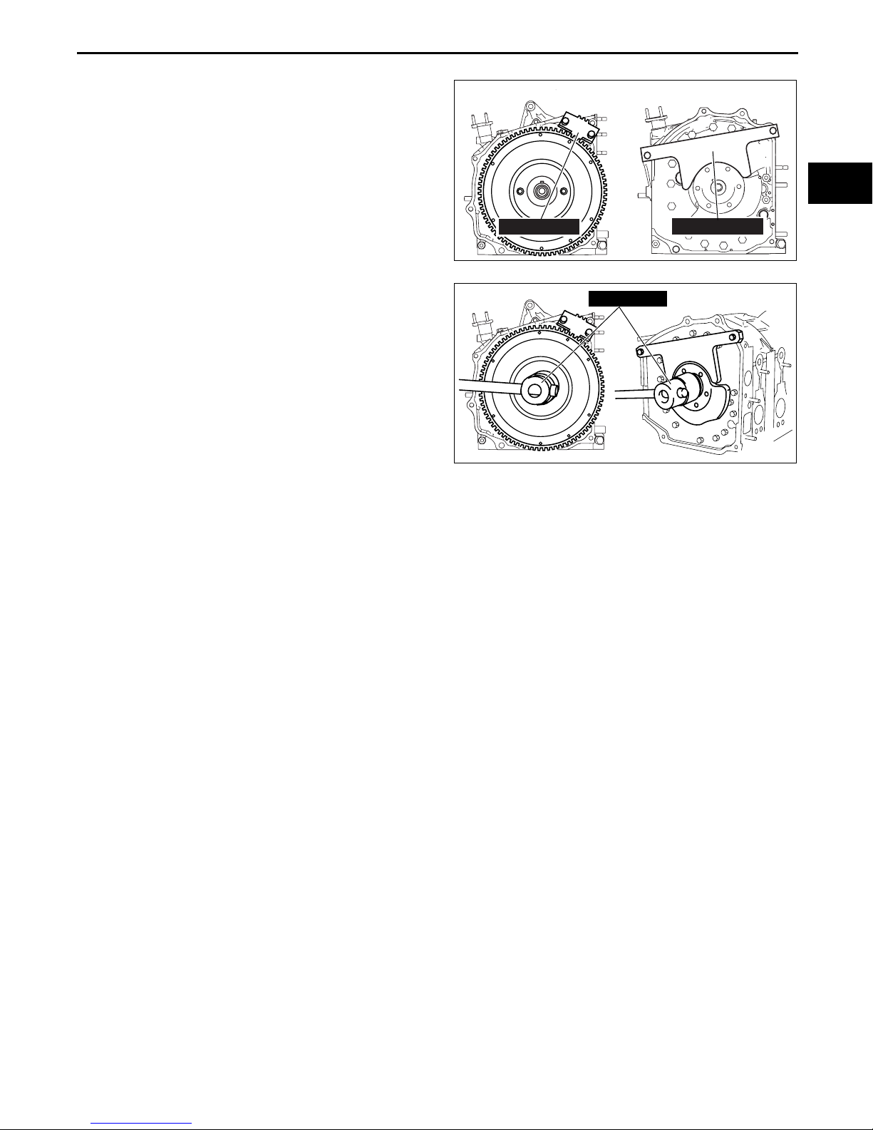
1. Lock the flywheel (MT) or counterweight (AT)
against rotation using the SSTs.
MT
AT
01–10
2. Tighten the locknut using the SST.
Tightening torque
392—490 N·m
{40.0—49.9 kgf·m, 290—361 ft·lbf}
End Of Sie
49 F011 101
MT
49 0820 035
49 1881 055A
BHJ0110E007
AT
BHJ0110E011
01–10–41
Page 59
Engine Workshop Manual 13B-MSP (Multi Side Port) (1773–1U–03C)
SEALANT
OIL
OIL
OIL
OIL
SEALANT
OIL
MECHANICAL
HOUSING ASSEMBLY II
CHU011002000E10
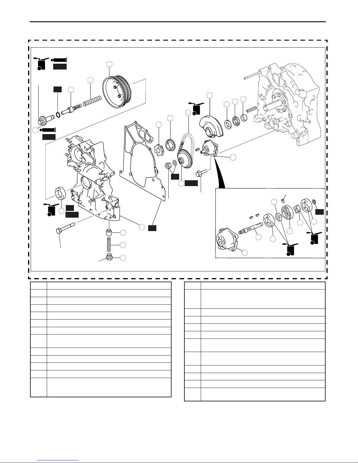
1. Assemble in the order indicated in the table.
Type A
SST
254—294
{25.9—29.9, 188—216}
R
23
22
24
11
10
8
9
14
13
16
25
SSTSST
12
R
SST
15
6.9—9.8
{0.8—0.9, 5.1—7.2}
31.4—46.1
R
20
SST
21
17
18.6—25.5 {1.90—2.60, 13.8—18.8}
39.2—49.0 {4.00—4.99, 29.0—36.1}
18
19
{3.21—4.70, 23.2—34.0}
R
0.98—2.94 {0.10—0.29, 0.73—2.16}
3
5
2
4
1
N·m {kgf·m, ft·lbf}
R
7
6
BHE0110E001
.
1 Oil pump body
2Shaft
3 Front inner rotor
4 Front outer rotor
5 Middle plate
6 Rear inner rotor
7 Rear outer rotor
8 Spacer
(See 01–10–43 Spacer Assembly Note.)
9 Needle bearing
10 Thrust plate
11 Balance weight
12 Oil pump component
13 Oil pump drive gear
(See 01–10–43 Oil Pump Drive Gear Assembly
Note.)
14 Oil pump chain
15 Oil pump sprocket wheel
(See 01–10–43 Oil Pump Sprocket Wheel Assembly
Note.)
16 Metering oil pump drive gear
17 Control valve
18 Control valve spring
19 Plug
20 Front oil seal
(See 01–10–43 Front Oil Seal Assembly Note.)
21 Front cover
(See 01–10–44 Front Cover Assembly Note.)
22 Spring
23 Eccentric shaft bypass valve
24 Pulley component
25 Pulley lockbolt
(See 01–10–44 Pulley Lockbolt Assembly Note.)
01–10–42
Revised 6/2008 (Ref. No. R108/08)
Page 60
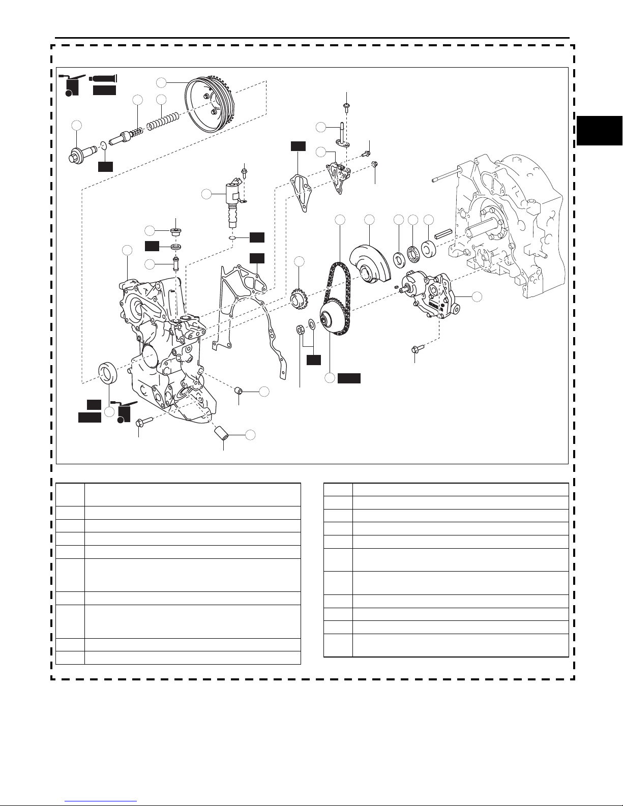
01–10-42 MECHANICAL
SEALANT
OIL
OIL
Typ e B
SEALANT
OIL
SST
254—294
{25.9—29.9, 188—216}
21
R
Engine Workshop Manual 13B-MSP (Multi Side Port) (1773–1U–03C)
MECHANICAL
19
20
18
7.8—10.8 {80—110 kgf
69.0—95.5 in
·lbf}
·cm,
7.8—10.8 {80—110 kgf
69.0—95.5 in
14
R
13
·lbf}
7.8—10.8 {80—110 kgf
69.0—95.5 in
·cm,
·cm,
·lbf}
CHU011002000E04
01–10
15
31.4—47.0 {3.21—4.79, 23.2—34.6}
12
R
17
11
7.8—10.8 {80—110 kgf
69.0—95.5 in
7
·lbf}
4
3
R
R
6
·cm,
1
2
5
R
8
31.4—46.1 {3.21—4.70, 23.2—34.0}
9
R
OIL
16
SST
18.6—25.5 {1.90—2.60, 13.8—18.8}
.
1 Spacer
(See 01–10–43 Spacer Assembly Note.)
2 Needle bearing
3 Thrust plate
4 Balance weight
5 Oil pump component
6 Oil pump drive gear
(See 01–10–43 Oil Pump Drive Gear Assembly
Note.)
7 Oil pump chain
8 Oil pump sprocket wheel
(See 01–10–43 Oil Pump Sprocket Wheel Assembly
Note.)
9 Plug
10 Oil filter joint
13.5—19.3 {1.38—1.96, 9.96—14.2}
10
29.4—40.2 {2.30—4.09, 21.7—29.6}
7.8—10.8 {80—110 kgf·cm, 69.0—95.5 in·lbf}
SST
N·m {kgf·m, ft·lbf}
GHE0110E003
11 OCV oil filter
12 Plug
13 OCV case
14 Oil pipe
15 OCV
16 Front oil seal
(See 01–10–43 Front Oil Seal Assembly Note.)
17 Front cover
(See 01–10–44 Front Cover Assembly Note.)
18 Spring
19 Eccentric shaft bypass valve
20 Pulley component
21 Pulley lockbolt
(See 01–10–44 Pulley Lockbolt Assembly Note.)
End Of Sie
Revised 6/2008 (Ref. No. R108/08)
01–10-42–1
Page 61

Engine Workshop Manual 13B-MSP (Multi Side Port) (1773–1U–03C)
MECHANICAL
THIS PAGE INTENTIONALLY
LEFT BLANK
01–10-42–2
Page 62
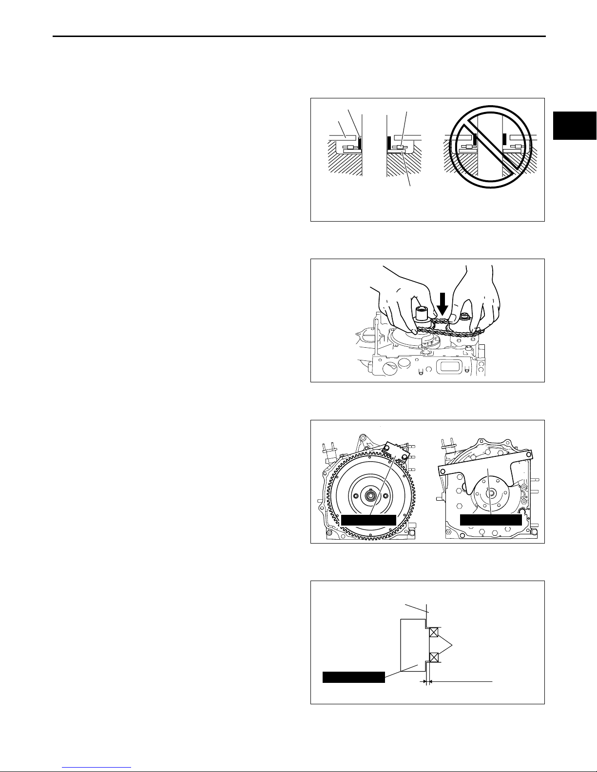
MECHANICAL
Spacer Assembly Note
Caution
•
• When assembling the spacer, do not allow the spacer to be caught in the needle b earing of the
••
plate.
Note
• Perform eccentric shaft end play inspection.
(See01–10–22 ECCENTRIC SHAFT END
PLAY INSPECTION.)
SPACER
PLATE
NEEDLE BEARING
THRUST PLATE
01–10
Oil Pump Drive Gear Assembly Note
1. Assemble the oil pump drive gear or oil pump
sprocket wheel with the oil pump chain engaged.
Oil Pump Sprocket Wheel Assembly Note
1. Lock the flywheel (MT) and counterweight (AT)
against rotation using the SSTs.
2. Assemble the oil pump shaft with a new lock
washer and locknut, and tighten.
Tightening torque
31.4—46.1 N·m
{3.21—4.70 kgf·m, 23.2—34.0 ft·lbf}
MT
GOOD
NO GOOD
CHU0110E019
BHJ0110E101
AT
3. Bend the lock wa sher and crimp.
Front Oil Seal Assembly Note
1. Press the oil seal in us ing the SST.
49 F011 101
FRONT COVER
49 F010 401A
49 1881 055A
BHJ0110E007
OIL SEAL
1.5—2.5 mm {0.06—0.09 in}
CHU0110E037
01–10–43
Page 63
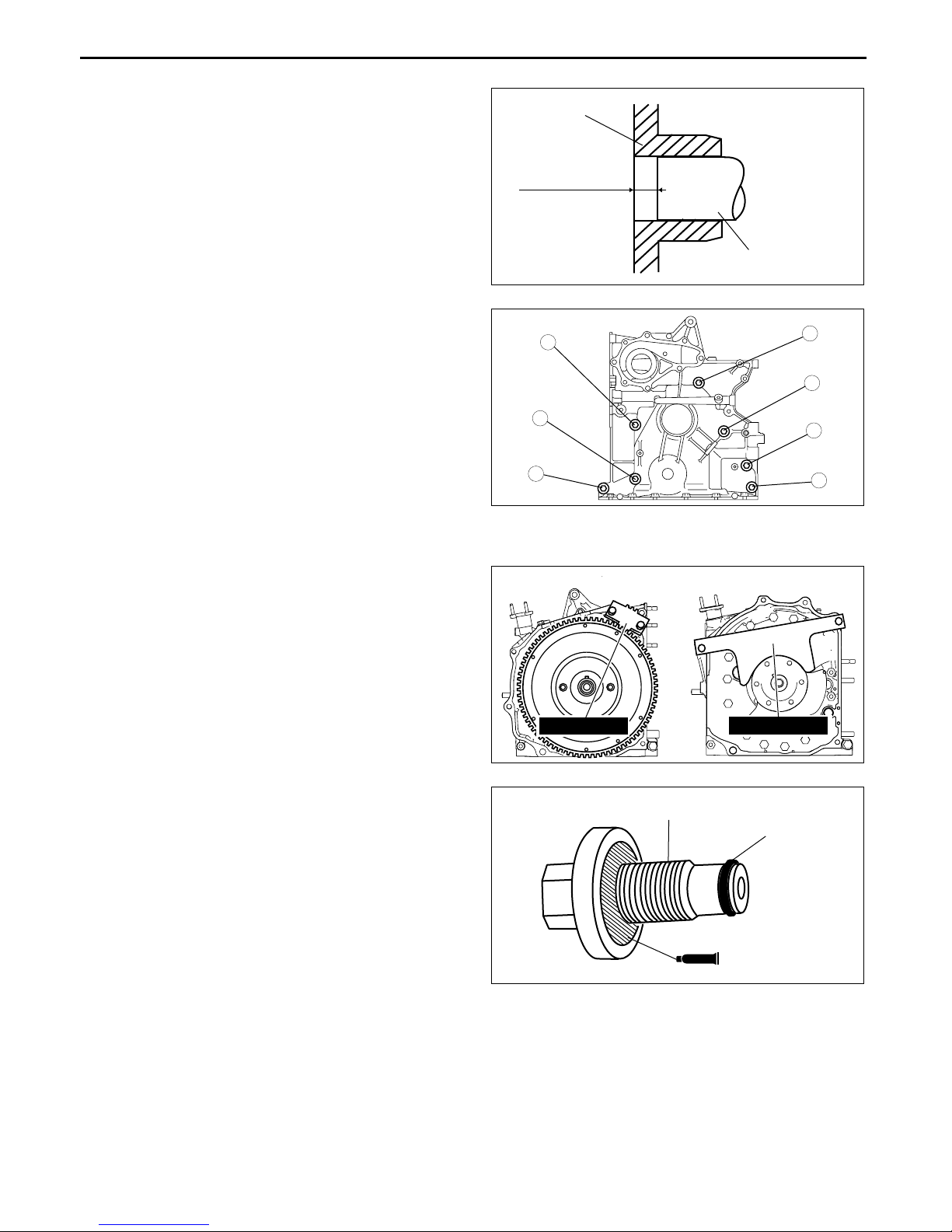
MECHANICAL
SEALANT
Front Cover Assembly Note
1. Before installing the front cover, install the pulley
boss to the eccentric shaft and measure the
height between the ecce ntr ic shaft top and the
pulley boss.
• If not within the specification, verify that the
spacer is not caugh t in the nee dl e beari ng.
Standard
10.34—11.14 mm {0.4071—0.4385 in}
2. Tighten the engine front cover installation bolts in
the order shown in the figure.
Tightening torque
18.6—25.5 N·m
{1.90—2.60 kgf·m, 13.8—18.8 ft·lbf}
PULLEY BOSS
10.34—11.14 mm
{0.4071—0.4385 in}
3
1
ECCENTRIC SHAFT
CHU0110E038
7
2
4
Pulley Lockbolt Assembly Note
1. Lock the flywheel (M T) or counterweight (AT)
against rotation using the SSTs.
2. Apply engine oil to the pulley lockbolt threads.
3. Assemble a new O-ring.
4. Apply silicone sealant to the seating face.
5. Tighten the pulley lockbolt .
Tightening torque
300—340 N·m
{30.6—34.6 kgf·m, 222—250 ft·lbf}
MT
5
49 F011 101
6
BHJ0110E098
AT
49 1881 055A
BHJ0110E007
ENGINE OIL
O-RING
End Of Sie
01–10–44
SEALANT
CHU0110E066
Page 64
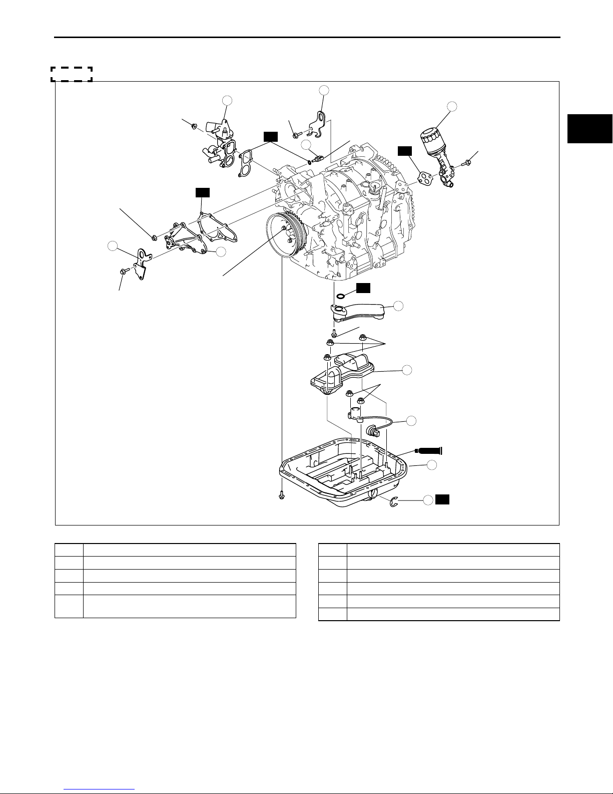
Engine Workshop Manual 13B-MSP (Multi Side Port) (1773–1U–03C)
SEALANT
MECHANICAL
HOUSING ASSEMBLY III
1. Assemble in the order indicated in the table.
Typ e A
18.6—25.5
{1.90—2.60, 13.8—18.8}
18.6—25.5 {1.90—2.60, 13.8—18.8}
8
14.2—17.2 {1.45—1.75, 10.5—12.6}
18.6—25.5 {1.90—2.60, 13.8—18.8}
6
31.4—46.1
{3.21—4.70, 23.2—34.0}
R
7
CHU011002000E11
10
11
15.7—23.5
R
9
{1.61—2.39, 11.6—16.5}
R
18.6—25.5
{1.9—2.6, 13.8—18.8}
R
01–10
1
7.8—10.8 {80—110 kgf
·cm, 69.0—95.5 in·lbf}
.
1 Oil strainer
2 Oil-level sensor
3 Oil baffle plate
4 Clip
5 Oil pan
(See 01–10–47 Oil Pan Assembly Note.)
8.8—11.8
{90—120 kgf
7.8—10.8 {80—110 kgf·cm, 69.0—95.5 in·lbf}
3
7.8—10.8 {80—110 kgf
2
·cm, 78—104 in·lbf}
6 Thermostat component
7 Water pump body
8 Engine hanger (engine front side)
9 Engine coolant temperature sensor
10 Engine hanger (engine rear side)
11 Oil filter component
·cm, 69.0—95.5 in·lbf}
5
R
4
N·m {kgf·m, ft·lbf}
CHU0110E054
Revised 6/2008 (Ref. No. R108/08)
01–10–45
Page 65
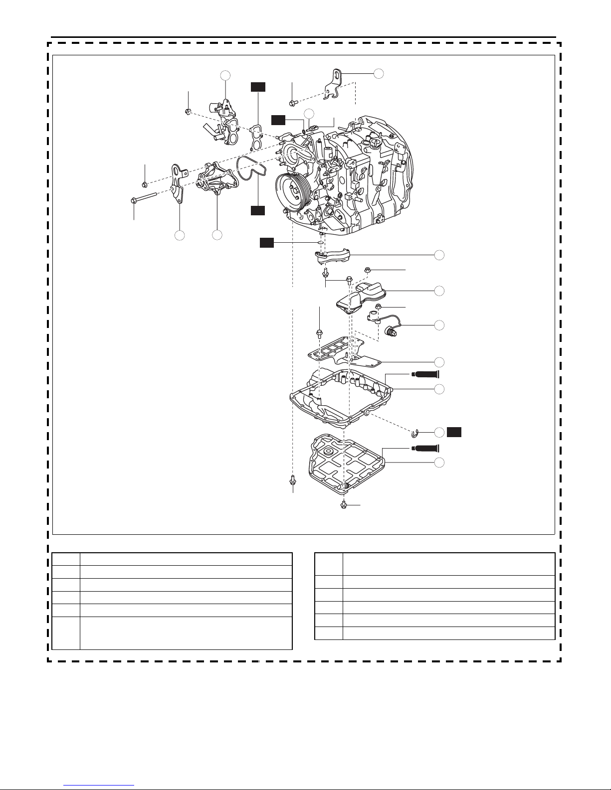
Type B
SEALANT
SEALANT
Engine Workshop Manual 13B-MSP (Multi Side Port) (1773–1U–03C)
18.6—25.5 {1.90—2.60,
13.8—18.8}
18.6—25.5 {1.90—2.60,
13.8—18.8}
18.6—25.5 {1.90—2.60,
13.8—18.8}
10
MECHANICAL
31.4—46.1
8
{3.21—4.70, 23.2—34.0}
R
15.7—23.5
{1.61—2.39, 11.6—16.5}
11
R
R
9
R
12
1
7.8—10.8 {80—110 kgf
69.0—95.5 in
·lbf}
·cm,
.
1 Oil strainer
2 Baffle plate
3 Oil level switch
4Clip
5 Baffle plate
6 Oil pan upper block
(See 01–10–47 Oil Pan Upper Block Assembly
Note.)
7.8—10.8 {80—110 kgf
69.0—95.5 in
18.6—25.5 {1.90—2.60, 13.8—18.8}
·lbf}
·cm,
7Oil pan
8 Thermostat component
9 Water pump body
10 Engine hanger (engine front side)
11 ECT sensor
12 Engine hanger (engine rear side)
5
7.8—10.8 {80—110 kgf
69.0—95.5 in
·lbf}
·cm,
3
2
SEALANT
6
R
4
SEALANT
7
7.8—10.8 {80—110 kgf
69.0—95.5 in
·lbf}
(See 01–10–47 Oil Pan Assembly Note.)
·cm,
N·m {kgf·m, ft·lbf}
GHE0110E004
01–10–46
Revised 6/2008 (Ref. No. R108/08)
Page 66
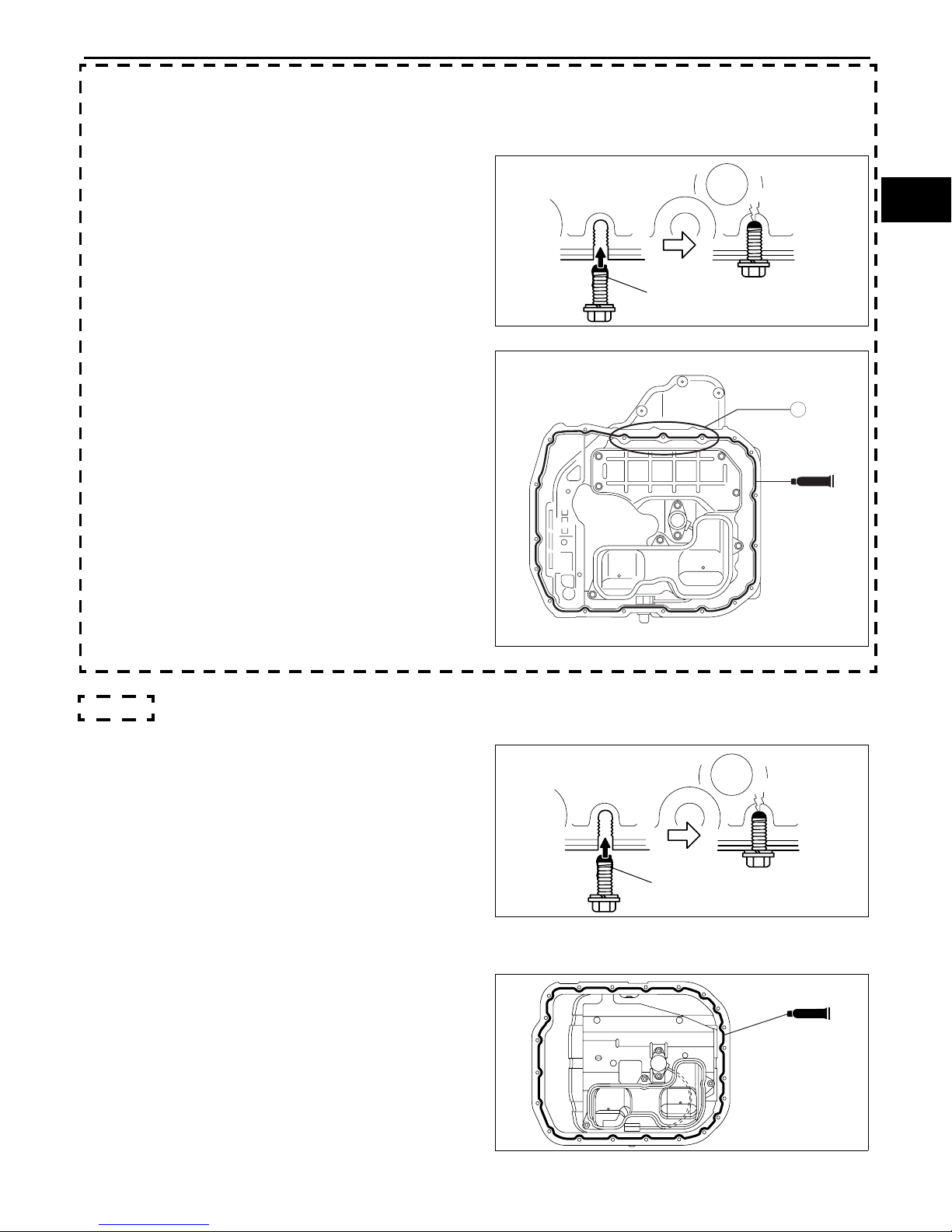
Engine Workshop Manual 13B-MSP (Multi Side Port) (1773–1U–03C)
SEALANT
SEALANT
MECHANICAL
Oil Pan Upper Block Assembly Note
Caution
• Apply the silicon sealant in a single, unbroken line around the whole perimeter.
• Install the oil pan upper block within 5 min after applying the silicone sealant.
• Using bolts with the old seal adhering
could cause cracks in the housing.
1. Completely clean and remove any oil, dirt, sealant
or other foreign material that may be adhering to
the oil pan upper block and housing.
2. When reusing the oil pan upper block installation
bolts, clean any old sealant from the bolts.
3. Apply silicone sealant to the areas as shown in
the figure.
OLD SEALANT
DAMAGE
01–10
CHU0111W004
Caution
• Apply silicone sealant to the outer
circumference of the bolt hole at
locations A shown in the figure.
Thickness
2.5—6.5 mm {0.10—0.26 in}
4. Install the oil pan upper block to the housing.
5. Tighten the oil pan upper block installation bolts.
Tightening torque
18.6—25.5 N·m {1.9—2.6 kgf·m, 13.8—18.8
ft·lbf}
Oil Pan Assembly Note
Typ e A
Caution
• Using bolts with the oil sealant still
adhering could cause cracks in the
housing. Clean all sealant off all oil pan
bolts before assembly.
• Apply the silicon sealant in a single,
unbroken line around the whole
perimeter.
• Install the engine front cover within 5 min
after applying the silicone sealant.
A
SEALANT
BHJ0110F010
DAMAGE
OLD SEALANT
1. Completely clean and remove any oil, dirt, sealant
or other foreign material that may be adhering to
the housing and oil pan.
2. When reusing oil pan installation bolts, clean any old sealant from the bolts.
3. Apply silicone sealant to the areas shown in the
figure.
Bead thickness
2.5—6.5 mm {0.1—0.2 in}
4. Tighten the oil pan installation bolts.
Tightening torque
8.8—11.8 N·m
{90—120 kgf·cm, 78—104 in·lbf}
Revised 6/2008 (Ref. No. R108/08)
CHU0111W004
SEALANT
BHJ0110E100
01–10–47
Page 67
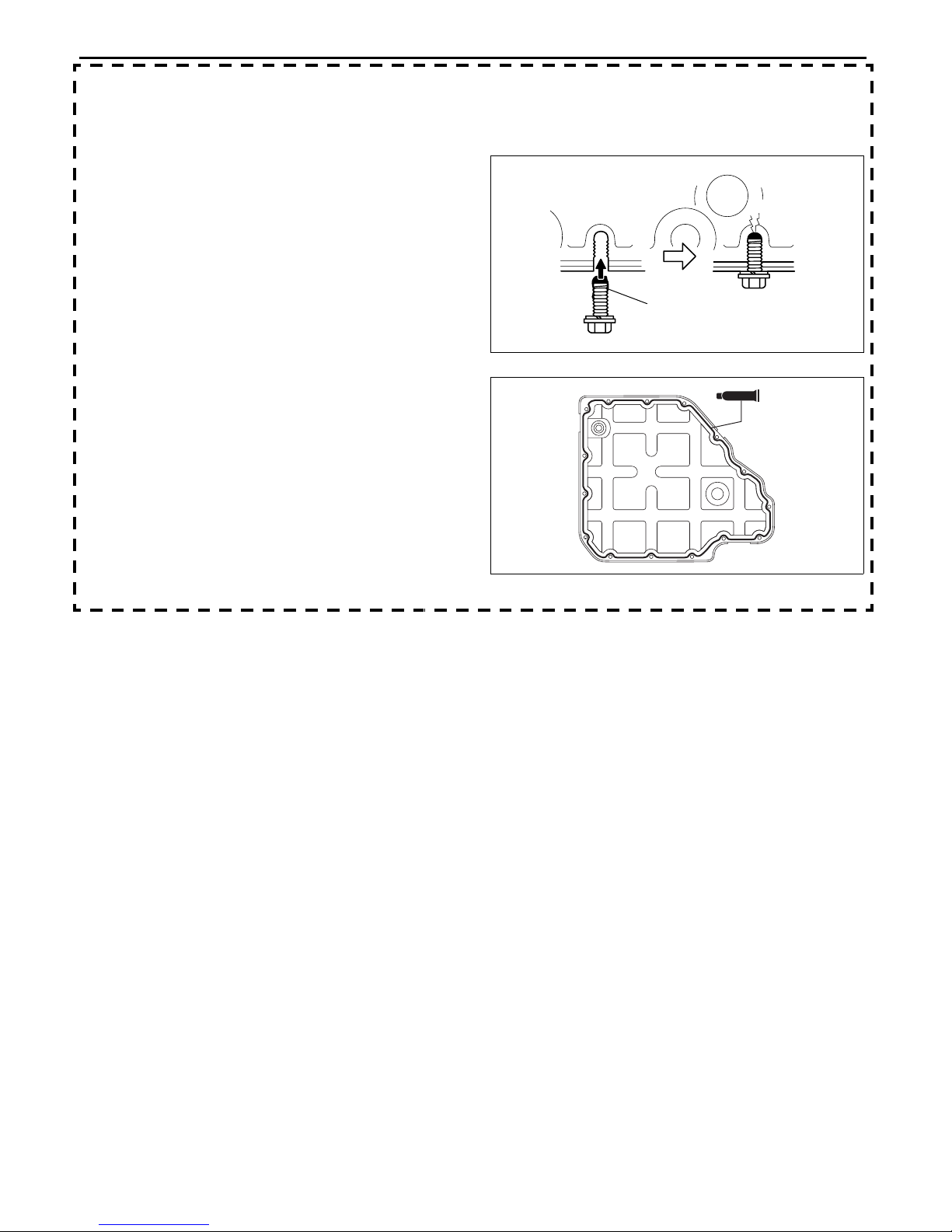
Engine Workshop Manual 13B-MSP (Multi Side Port) (1773–1U–03C)
SEALANT
MECHANICAL
Type B
Caution
• Apply the silicon sealant in a single, unbroken line around the whole perimeter.
• Install the oil pan within 5 min after applying the silicone sealant.
• Using bolts with the old seal adhering
could cause cracks in the housing.
1. Completely clean and remove any oil, dirt, sealant
or other foreign material that may be adhering to
the oil pan upper block and oil pan.
2. When reusing the oil pan installation bolts, clean
any old sealant from the bolts.
3. Apply silicone sealant to the areas as shown in
the figure.
Thickness
2.5—6.5 mm {0.10—0.26 in}
4. Install the oil pan to the oil pan upper block.
5. Tighten the oil pan installation bolts.
Tightening torque
7.8—10.8 N·m {80—110 kgf·cm, 69.0—95.5
in·lbf}
End Of Sie
DAMAGE
OLD SEALANT
CHU0111W004
SEALANT
AR8WZW000007
01–10–48
Revised 6/2008 (Ref. No. R108/08)
Page 68
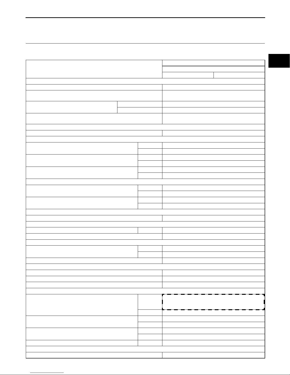
Engine Workshop Manual 13B-MSP (Multi Side Port) (1773–1U–03C)
01–50 TECHNICAL DATA
ENGINE TECHNICAL DATA . . . . . . . . . . 01–50–1
End of Toc
ENGINE TECHNICAL DATA
ITEMS
SIDE HOUSING (FRONT, INTERMEDIATE, REAR) INSPECTION
Maximum distortion (mm {in}) 0.04 {0.0016}
Maximum wear
(Vertical wear)
Maximum wear
(Convex oval)
Maximum wear
(Oil seal stepped path wear)
ROTOR HOUSING
Maximum width difference (mm {in}) 0.06 {0.0024}
ROTOR
Rotor and side housing clearance (mm {in})
Protrusion of the rotor round (mm {in})
Apex seal groove and the apex seal clearance (mm {in})
APEX SEAL, APEX SEAL SPRING
Apex seal height (mm {in})
Apex seal spring height (mm {in})
CORNER SEAL, CORNER SEAL SPRING
Minimum projection of the corner seal (mm {in}) 0.5 {0.02}
SIDE SEAL, SIDE SEAL SPRING
Corner seal and side seal clearance (mm {in}) Maximum 0.4 {0.016}
Minimum projection of the side seal (mm {in}) 0.5 {0.02}
CUT-OFF SEAL, CUT OFF SEAL SPRING
Cut-off seal height (mm {in})
Minimum projection of the cut off seal (mm {in}) 0.5 {0.02}
OIL SEAL, OIL SEAL SPRING
Maximum contact width (mm {in}) 0.5 {0.02}
Maximum circumferential width (mm {in}) 2.5 {0.098} (or 10 nicks or more)
Minimum projection of the oil seal (mm {in}) 0.5 {0.02}
ECCENTRIC SHAFT
Main bearing oil clearance (mm {in})
Rotor bearing oil clearance (mm {in})
Runout (mm {in})
End play (mm {in}) Standard 0.04—0.09 {0.0016—0.0035}
ECCENTRIC SHAFT BYPASS VALVE
Minimum projection (mm {in}) 6 {0.24}
Revised 6/2008 (Ref. No. R108/09)
(mm {in})
TECHNICAL DATA
ENGINE TYPE
13B-MSP
STANDARD POWER HIGH POWER
(mm {in}) 0.10 {0.0039}
Oil seal inner path 0.01 {0.0004}
Oil seal outer path 0.10 {0.0039}
(mm {in}) 0.02 {0.0008}
Standard 0.05—0.19 {0.0020—0.0074}
Maximum 0.05 {0.002}
Standard 0.12—0.18 {0.0048—0.0070}
Minimum 0.1 {0.0039}
Standard 0.042—0.077 {0.0017—0.0030}
Maximum 0.15 {0.0059}
Standard 5.3 {0.20}
Minimum 4.3 {0.17}
Standard 5.4 {0.213}
Minimum 3.5 {0.148}
Standard 3.95 {0.1555}
Minimum 3.8 {0.15}
Without stopper screw: 0.045—0.085 {0.0022—
Standard
With stopper screw: 0.055—0.075 {0.0018—0.0033}
Maximum 0.1 {0.0039 in}
Standard 0.06—0.08 {0.0024—0.0030}
Maximum 0.1 {0.0039}
Standard 0.02 {0.0008}
Maximum 0.06 {0.0024}
0.0029}
CHU015001001E02
01–50
01–50–1
Page 69

Engine Workshop Manual 13B-MSP (Multi Side Port) (1773–1U–03C)
TECHNICAL DATA
ITEMS
OIL PUMP
Body clearance (Type A) (mm {in})
Tip clearance (Type A) (mm {in})
Side clearance (Type A) (mm {in})
End Of Sie
ENGINE TYPE
13B-MSP
STANDARD POWER HIGH POWER
Standard 0.20—0.25 {0.0079—0.0098}
Maximum 0.3 {0.0118}
Standard 0.03—0.12 {0.0012—0.0047}
Maximum 0.15 {0.0059}
Standard 0.03—0.125 {0.0012—0.0049}
Maximum 0.15 {0.0059}
01–50–2
Revised 6/2008 (Ref. No. R108/08)
Page 70
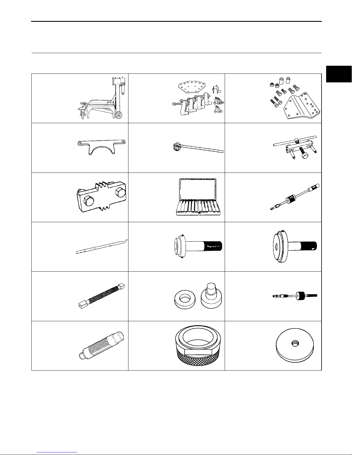
SERVICE TOOLS
01–60 SERVICE TOOLS
ENGINE SST . . . . . . . . . . . . . . . . . . . . . . 01–60–1
End of Toc
ENGINE SST
49 0107 680A
49 L010 1A0
49 J010 3A0A
CHU016001001E02
01–60
Engine stand
49 1881 055A
Stopper counter
weight (AT)
49 F011 101
Ring gear brake
(MT)
49 0813 225A
Oil seal remover
Engine hanger
set
49 0820 035
Flywheel box
wrench
49 0813 250
Seal case
49 0813 235
Main bearing
puller and
installer
Hanger, Engine
stand
49 0839 305A
Counterweight
puller
49 0813 215A
Dowel puller
and oil pump
puller
49 0813 240
Rotor bush
puller and
installer
49 0839 165
Corner seal
gauge
49 G030 797
Handle (MT)
End Of Sie
49 F011 1A1
Bearing installer
set (MT)
49 F010 401A
Installer
49 1285 071
Needle bearing
puller (MT)
49 J027 001
Bearing installer
01–60–1
Page 71

 Loading...