

Mazda 0000-8C-Z05, 0000-8C-L27 Instructions Manual
GENUINE ACCESSORIES
INSTALLATION INSTRUCTIONS
PART NUMBERS: APPLICABLE MODELS:
0000-8C-Z05 Electrochromic Mirror w/ Compass/Temp/HL 2006 > Mazda5
®
0000-8C-L27 Compass/Temp/HomeLink
Installation Kit
REQUIRED COMPONENTS:
ITEM QTY DESCRIPTION SERVICE PART NUMBER
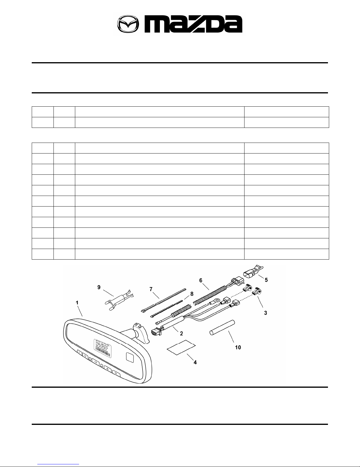
1 1 Mirror Assembly with Compass, Temp and HomeLink® 0000-8C-Z05
INSTALLATION KIT COMPONENTS:
2 1 Harness Assembly – Power, Battery and Ground 000-8C-H12
3 2 Wire Tap 000-8C-H09
4 3 Foam Tape --
5 1 Temperature Sensor 000-8C-G18
6 1 Harness Assembly – Temperature Sensor 000-8C-G17
7 4 Tie Wrap (Long) --
8 1 Tie Wrap (Short) --
9 1 Wire Cover 000-8C-H11
10 1 Protective Sleeve --
11 1 Installation Instructions --
12 1 User Guide --
HOMELINK
TOOLS REQUIRED:
Clean Rag
Fiberstick
Pliers
Fish Wire #T20 Torx Wire Cutters
Electrical Tape Ratchet Phillip's Screwdriver
4mm Flat Screwdriver 10mm Socket
®
AND THE HOMELINK HOUSE® ARE REGISTERED TRADEMARKS OF JO HNSON CONTROLS, INC.
Page 1 of 13 Revision A 550-0339
INSTALLATION PRECAUTIONS / NOTES: INSTALLATION PRECAUTIONS / NOTES:
• Do not use excessive force when removing OE mirror from windshield. • Do not use excessive force when removing OE mirror from windshield.
• Do not push fish wire too far into dash to avoid damage to existing components. • Do not push fish wire too far into dash to avoid damage to existing components.
• Do not place wire harness against objects with sharp edges that may cause electrical
• Do not place wire harness against objects with sharp edges that may cause electrical
shorting.
shorting.
• On vehicles equipped with “A” pillar air bag, verify mirror harness path remains clear of
• On vehicles equipped with “A” pillar air bag, verify mirror harness path remains clear of
air bag. Harness should follow, and be tied to existing OEM wiring with tie wraps.
air bag. Harness should follow, and be tied to existing OEM wiring with tie wraps.
• Verify that power harness path will not interfere with brake, clutch, emergency brake or
• Verify that power harness path will not interfere with brake, clutch, emergency brake or
air bag operation. Use tie wraps to hold the wiring away from critical locations.
air bag operation. Use tie wraps to hold the wiring away from critical locations.
Pe
rform the following pre-installation steps:
1
P P
surface and inspect for damage or defects.
2) Record customer’s programmed radio stations (if
applicable).
1
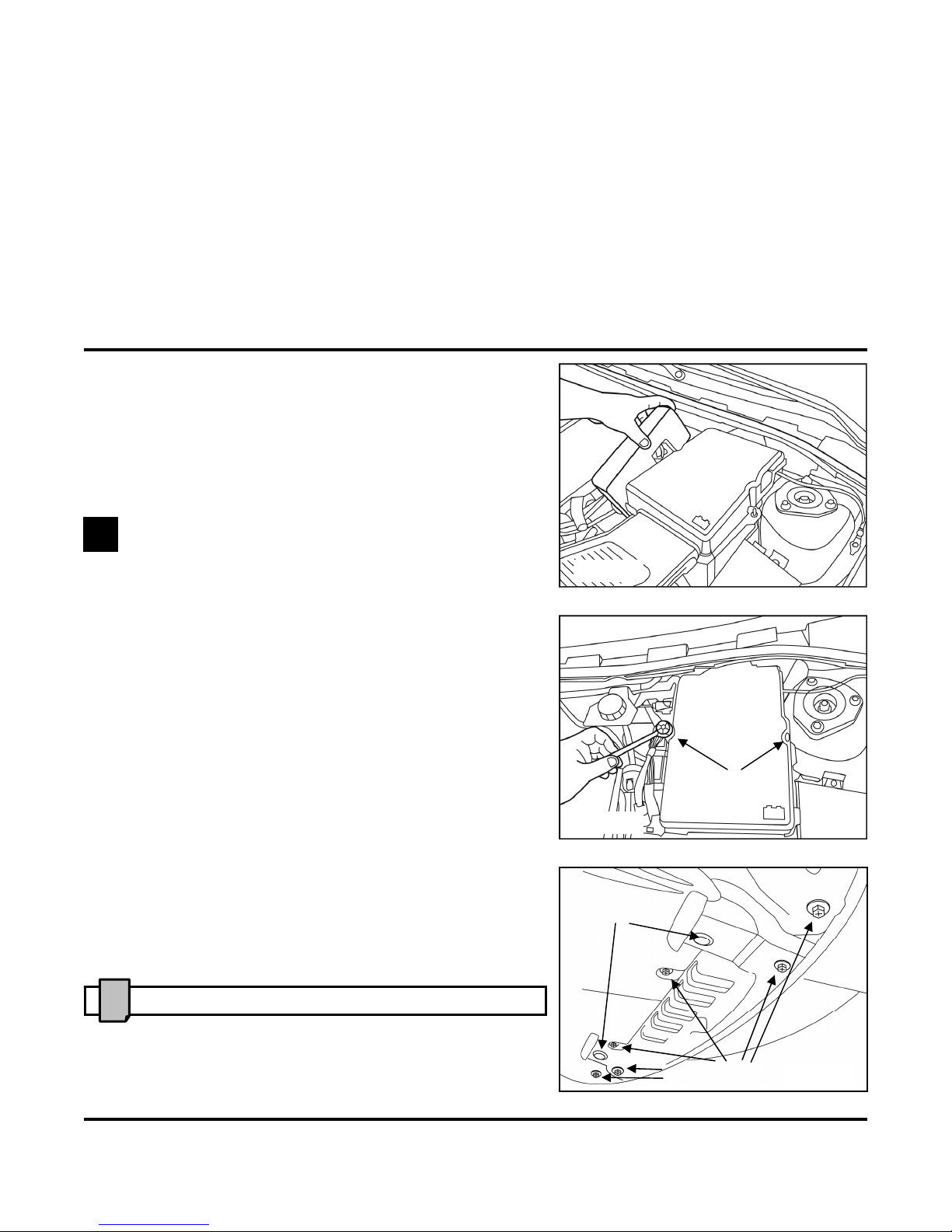
1) Disconnect negative battery terminal.
a) Remove relay cover by grasping rear of
cover and pulling upwards. Disengage the
locking tab at the front of cover. (Fig. 1-1)
b) Remove two (2) 10mm bolts from
battery cover. Disengage locking tabs and
remove cover. (Fig. 1-2)
c) Disconnect negative battery terminal.
2) Disengage front edge of vehicle engine splash guard.
a) Remove six (6) Phillip’s screws and two (2)
plastic push-pin from passenger-side of vehicle
NOTE
engine splash guard. (Fig. 1-3)
engine splash guard. (Fig. 1-3)
1
) Place kit components on a clean, padded
Preparation
!
This allows access to front radiator area later during installation.
Fig. 1-1
10mm Bolts
Fig. 1-2
Push-pins
e
Phillip’s Screws
Fig. 1-3
Page 2 of 13 Revision A 550-0339
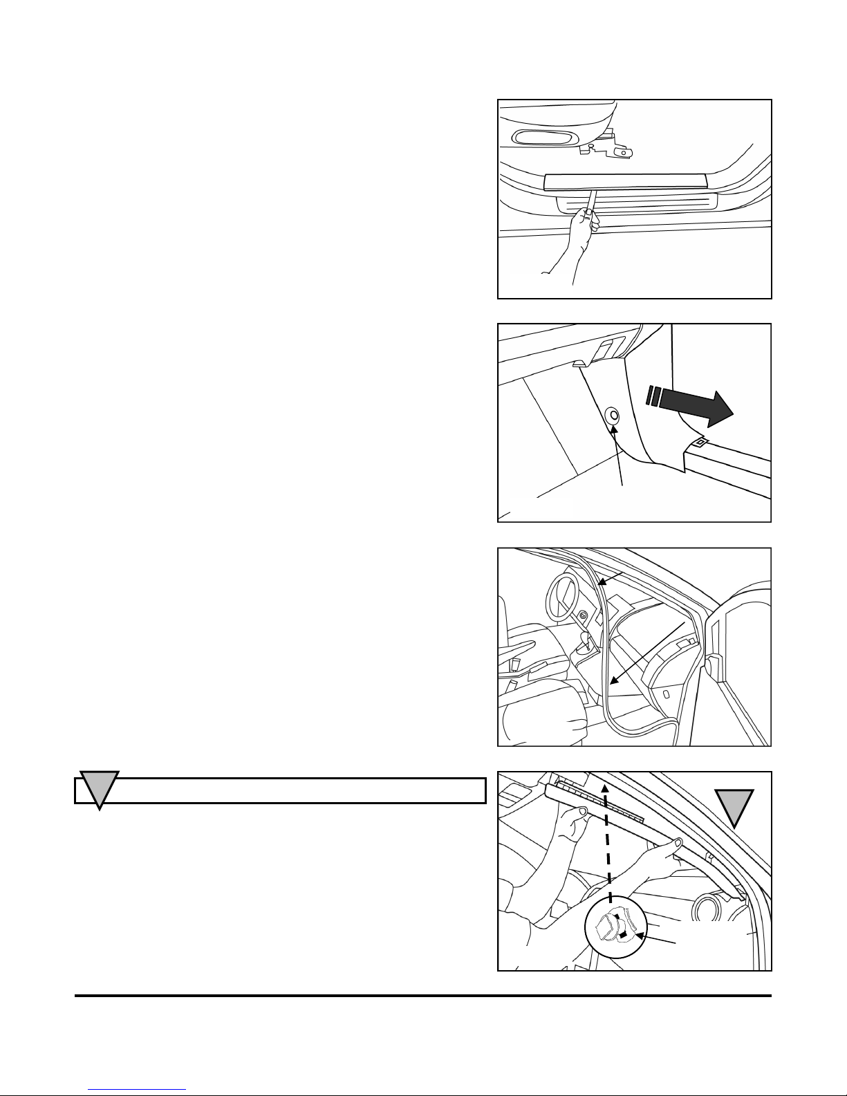
3) Remove passenger-side scuff plate.
a) Use fiberstick to disengage clips. (Fig. 1-4)
4) Remove passenger-side kick plate.
a) Use 4mm screwdriver to release center
of plastic pushpin.
b) Grasp kick plate at rear and pull out
towards rear of vehicle.
(Fig. 1-5)
5) Loosen passenger side door seal past top
of A-pillar. (Fig. 1-6)
CAUTION
a) Pull out top of A-pillar trim towards
driver side of vehicle until A-pillar push-pin
connector is fully extended. (Fig. 1-7)
6) Remove A-pillar trim.
!
Do not use excessive force. A-pillar connector could be damaged.
b) Pull A-pillar trim towards the rear of the
vehicle to release the base and to slide up to
release from A-pillar push-pin connector.
(Fig. 1-7)
Fig. 1-4
Fig. 1-5
Fig. 1-6
Fig. 1-7
Push-pin
CAUTION
!
A-pillar
Push-pin
Connector
Page 3 of 13 Revision A 550-0339
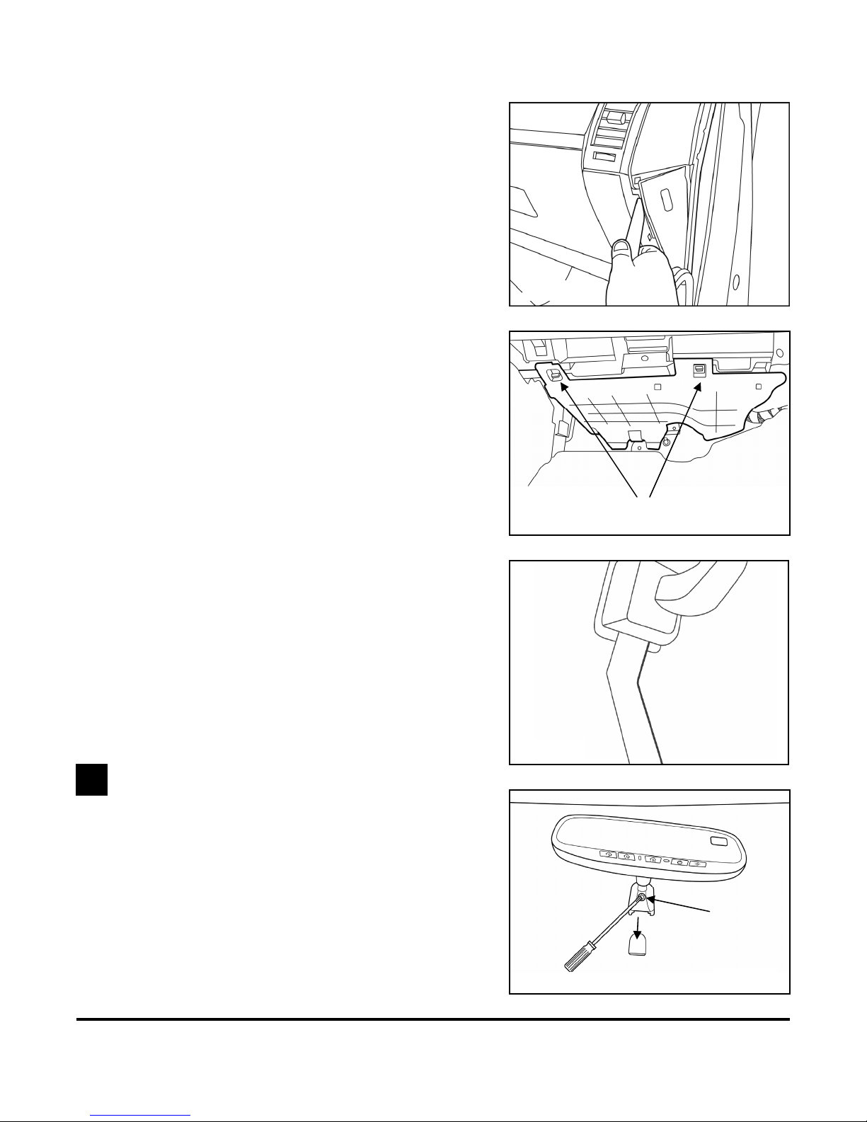
8) Remove passenger-side under-dash cover.
a) Depress plastic clips at front edge of
cover.
b) Lower front edge of cover and remove.
(Fig. 1-9)
a) Insert fiberstick between bottom of mirror mount
and windshield glass.
b) Push fiberstick up into mount to disengage
locking tab. Pull up while gently wiggling mirror
to remove.
2
1) Attach EC mirror.
a) Hold the mirror head and slide the mount
downwards as far as possible over the windshield
button, until fully seated.
b) Using a #T20 Torx, tighten the mirror mounting
bracket screw to 1.3 ft-lbs (17.8 kg-cm).
(Fig. 2-1)
7) Using fiberstick, remove fuse box cover. (Fig. 1-8)
9) Remove OE mirror.
EC Mirror Installation
Fig. 1-8
Fig. 1-9
Fig. 1-10
Fig. 1-10
Plastic Clips
1.3 ft-lbs
Fig. 2-1
Page 4 of 13 Revision A 550-0339
 Loading...