

Mazda 0000 81 M09 Instructions Manual
Mazda CX-7-1
GENUINE SATELLITE RADIO KIT
INSTALLATION INSTRUCTIONS
Thank you for purchasing a genuine Mazda accessory.
Before removal and installation, be sure to thoroughly read these instructions.
Please read the contents of this booklet in order to properly install and use the satellite
radio kit. Your safety depends on it.
Keep these instructions with your vehicle records for future reference.
• There are several WARNING and CAUTION sections in this booklet concerning
safety when installing. Always read and follow them in order to prevent injuries,
accidents, and possible damage to the vehicle.
WARNING: Indicates a situation in which serious injury or death could result if the
warning is ignored.
CAUTION: Indicates a situation in which bodily injury or damage to the vehicle
could result if the caution is ignored.
• If in any doubt, please ask your Mazda dealer to install the accessory in order to
prevent errors in installation.
• If you have any questions about the use of the accessory, ask your Mazda dealer for
proper advice before using it.
• Mazda and its suppliers are not responsible for injuries, accidents, and damage to
persons and property that arise from the failure of the dealer or installer to follow these
instructions.
• To ensure safety and reliability of the work, installation, removal and disposal work
done by an Authorized Mazda Dealership is recommended.
• Be careful not to lose removed parts, and be sure that they are kept free from
scratches, grease or other dirt.
PART NAME: SATELLITE RADIO KIT
PART NUMBER: 0000 81 M09 (Harness Kit H5)
VEHICLE: Mazda CX-7
1ED6P11A22600
To the dealer
• Please turn over these instructions to the customer after installation.
To the customer
• Keep these instructions after installation. The instructions may be necessary for
installing other optional parts or removal of this accessory.
• Should the vehicle or this accessory be resold, always leave these instructions
with it for the next owner.
Note
WARNING
Mazda CX-7-2
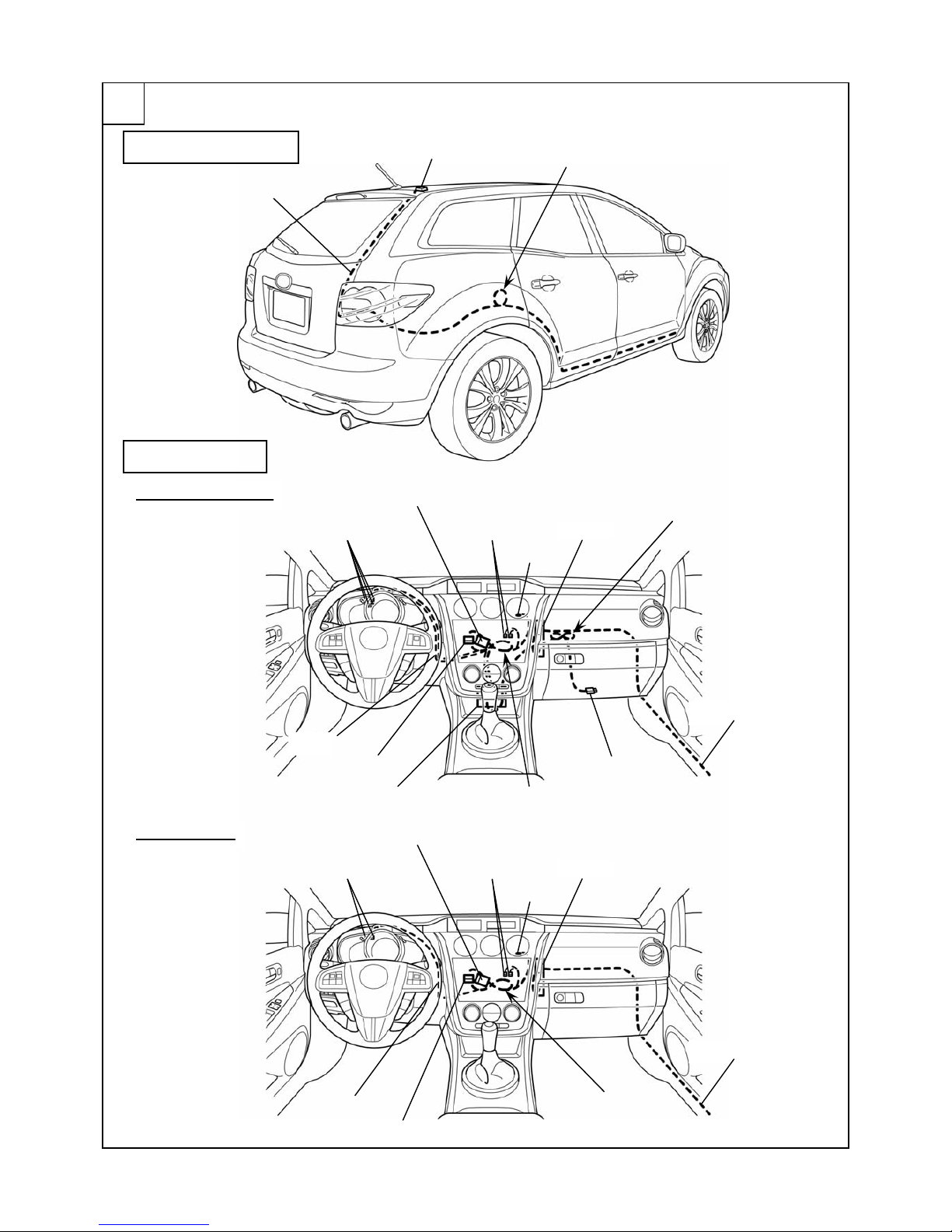
INSTALLATION VIEW
1
DLP unit
Antenna cable
Antenna
iPod connection cable
To Audio unit
iPod integration module
SIRIUS and iPod
ANTENNA CABLE
HARNESS (H5)
SIRIUS only
Antenna cable
Tie redundant part
(Harness (H5))
Tie redundant part
(Antenna cable)
Electro tap
【CAN (+) and CAN (-)】
To AUX or Bluetooth H/F
Electro tap
【+B and ACC】
GND
Harness (H5)
Tie redundant part
(iPod connection cable)
DLP unit
To Audio unit
Antenna cable
Tie redundant part
(Harness (H5))
Electro tap
【CAN (+) and CAN (-)】
To AUX or Bluetooth H/F
Electro tap
【+B and ACC】
GND
Harness (H5)

Mazda CX-7-3
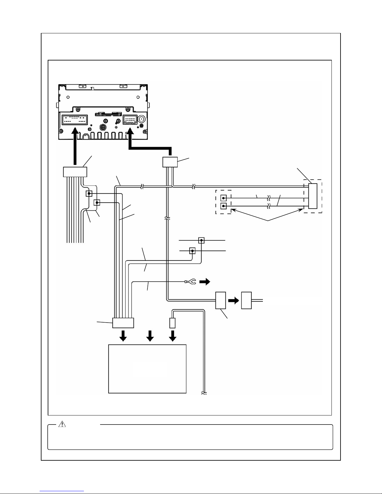
CONNECTION DIAGRAM
<Installation of SIRIUS and iPod integration module>
2
• When connecting a connector, be sure to insert it straight along the guide.
The connector terminal may be bent if inserted at an angle.
CAUTION
iPod
(On market product)
DLP unit
(SIRIUS)
Antenna cable
To AUX or Bluetooth H/F
iPod
integration module
NO
CONNECT
iPod connection cable
Audio unit
16 pin connector (White)
To audio bracket
CAN (+)
CAN (-)
Harness (H5)
CAN (-)
CAN (+)
+B
ACC
A
udio 24-pin
connector
ACC
GND
+B
CAN (+)
NO CONNECT
16 pin connector
(Gray)
8 pin connector
16 pin connector (Black)
Mazda CX-7-4
<Installation of SIRIUS only >
• When connecting a connector, be sure to insert it straight along the guide.
The connector terminal may be bent if inserted at an angle.
CAUTION
Antenna cable
To AUX or Bluetooth H/F
Not used
(Wrap with sponge and vinyl tape)
Audio unit
To audio bracket
CAN (+)
CAN (-)
Harness (H5)
CAN (-)
CAN (+)
+B
ACC
A
udio 24-pin
connector
ACC
GND
+B
CAN (-)
CAN (+)
NO
CONNECT
DLP unit
(SIRIUS)
16 pin connector (White)
16 pin connector
(Gray)
8 pin connector
16 pin connector (Black)
Mazda CX-7-5
PARTS
Main Kit (0000 81 Z40)
Part Part name Qty. Part Part name Qty. Part Part name Qty.
Antenna 1 DLP unit 1
Alcohol wipe 1
Nut 2
Harness Kit H5 (0000 81 M09)
Part Part name Qty. Part Part name Qty. Part Part name Qty.
Harness (H5) 1
Double-sided
adhesive tape
4
Pad protector 20
Urethane 2
Sponge 2
Tie wrap
(Small)
3
Tie wrap
(Large)
20
Clip 3
Butyl tape 1
Installation
instructions
1
BEFORE INSTALLATION
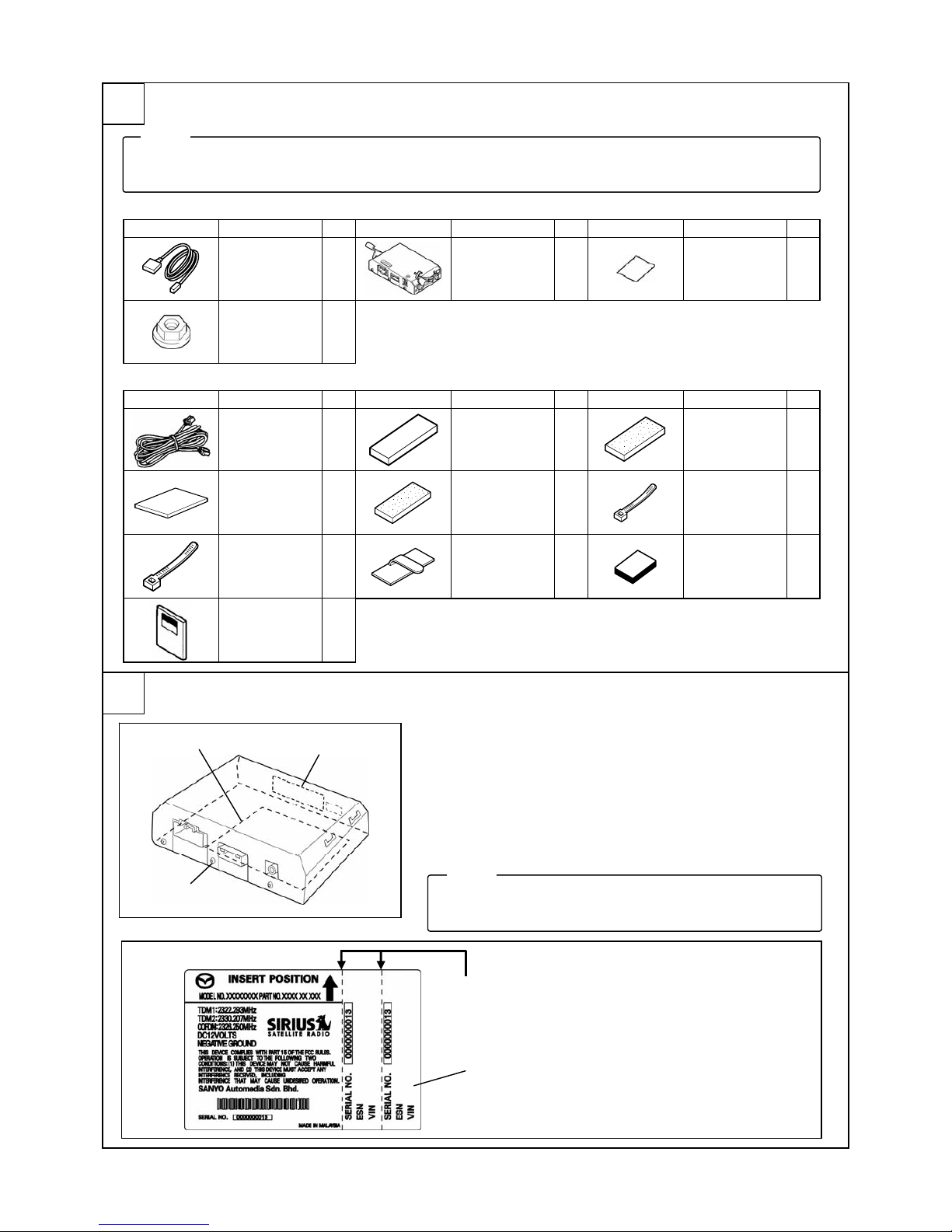
Rating Label Removal
1. Tear off lower part of the rating label on the bottom of DLP
unit.
2. If there is nothing written in the Sirius ID (ESN) space of
the rating label, write down the 12-digit number printed in
the location shown in the figure.
3. Affix one rating label in the last page of the Owner’s
Manual.
3
• Verify that the kit includes all the following parts and that they are free of dirt, scratches or damage.
• All hardware required to install is contained in the two Satellite Radio Kits below.
Note
4
•
The other rating label is for the dealer (port) records.
• Do not fail to submit the record.
Note
DLP unit
Rating label
Sirius ID (ESN)
Rating label
Tear off
① Affix to the back of the Owner’s Manual.
② Submit to the manager of installation department.
② ①

Mazda CX-7-6
REQUIRED TOOLS
Prepare the following tools or items before installation.
●Electrical vinyl tape ●Mat ●Scissors ●Scale ●Touch-up paint or Zinc primer
●Phillips screwdriver ●Socket driver (8 mm, 10 mm, 14 mm) ●Torx wrench ●Wrench ●File
●ISP alcohol
WARNING
When the negative battery
cable is connected during
operation, it may cause
electric shock or other
personal injuries.
Disconnect the negative
battery cable before
removal/installation.
When
connecting/disconnecting
connectors, grasp the
connectors, not the wires.
Otherwise a short, an
accident from poor contact
or fire may occur.
Do not pull the harness
with excessive force. Doing
so can cause a breakage
or a short-related accident,
as well as an electrical
short or fire.
Secure the harness with
the band (part included) so
it doesn’t dangle. If not, it
may cause a short,
accident, or fire.
CAUTION
Put the removed parts and
the parts in the kit on the
protective sheet to prevent
scratches.
Using improper tools may
cause damage and or
broken parts. Use the
correct tool for the job.
Be sure to cover the
vehicle body with
protectors or mats to
prevent stains, scratches
and damage when
removing/installing the
vehicle parts.
Excessive length of tie
wrap may interfere with
other parts and cause
damage.
Cut unnecessary part up to
about 5 mm {0.19 in} from
the fixed point.
Take care not to trap
antenna cable under
attachment nuts.
• When the negative battery cable is removed, the clock, radio, trip meters and other memories will be
erased. Before performing work, record the content of the memory.
Note
• When removing/installing the parts, park the vehicle on level
ground and apply the side brake securely. Be sure to turn the
ignition switch off, otherwise the vehicle can move, causing
personal injury or vehicle damage.
WARNING
•
During the installation of the antenna cable make
sure the cable is not pinched, knotted “kinked” or
coiled too tightly. It is recommended that a coil of
less than 20 mm {0.78 in} be avoided if possible.
• If this wiring procedure is not followed, the
performance of the antenna will be affected and
could result in increased audio muting.
CAUTION
20 {0.78}
mm {in}
Mazda CX-7-7
PART REMOVAL
Negative battery cable disconnection
1. Set the selector lever to D range.
2. Disconnect the negative battery cable and wrap tape around it to insulate.
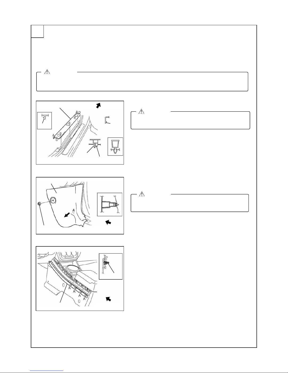
Front scuff plate inner (passenger’s side) removal
1. Pull the front scuff plate in ner upward while detaching tabs
A, detach clips B, pins C and tab D from the body, and
then remove the front scuff plate inner.
Front side trim (passenger’s side) removal
1. Remove the nut using 14mm socket.
2. Pull the front side trim in the direction shown by the arrow,
then detach clip A.
Console panel (driver’s and passenger’s side)
removal
1. Remove clips A in order starting from the vehicle rear
using a tape-wrapped flathead screwdriver.
5
• When the negative battery cable is connected during operation, it may cause electric shock o r other
personal injuries. Disconnect the negative battery cable before removal/installation.
WARNING
•
Be careful not to damage the scuff plate during
removal.
CAUTION
•
Be careful not to tear the seaming welt when puling it
out.
CAUTION
Pin C
Clip B
Front scuff plate inner
Tab D
Clip B detail
Tab A
Vehicle front
Front side trim
Clip A detail
Nut
Vehicle front
Clip A
Console panel
Vehicle front
Mazda CX-7-8
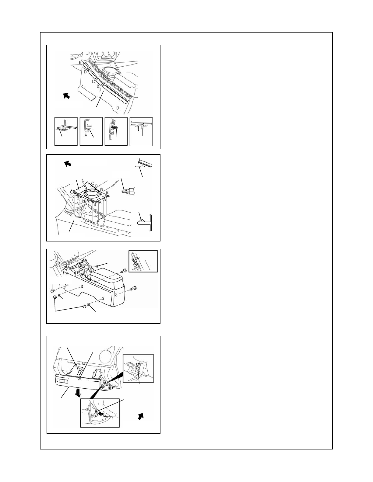
2. Remove the parts in the order of pin B, clip C and tab D
from the vehicle rear.
3. Remove the pin E.
4. Remove the console panel.
Panel removal
1. Remove the selector lever knob.
2. Pull the panel upward, then disengage clips A, clips B and
tabs C.
3. Disconnect the accessory socket connector.
4. Disconnect the seat warmer switch connectors.
(Vehicles with seat warmer system)
5. Remove the panel.
Console removal
1. Remove the covers.
2. Remove the fasteners and screws.
3. Remove the pins A.
4. Remove the console.
Glove compartment removal
1. Press the stay damper in the direction shown by the arrow
and detach it from the glove compartment lid.
2. Bend the stoppers inward to remove.
3. Turn the glove compartment downward and pull the pins.
4. Remove the glove compartment.
Stopper
Stay damper
Glove
compartment
Pin
Pin
Vehicle front
Console
Clip B
Panel
Clip A
Tab C
Vehicle front
Pin E
Console panel
Clip C
Pin B
Vehicle front
Tab D
Pin A
Scre
w
Cove
r
Scre
w
Scre
w
Fastene
r
Mazda CX-7-9
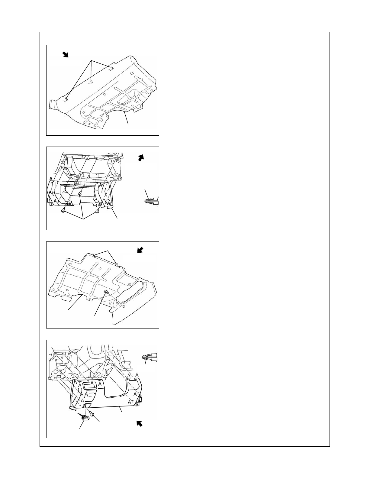
Lower panel (passenger’s side) removal
1. Pull the cover outward and detach the tabs.
2. Remove the cover.
3. Remove the screws.
4. Pull the lower panel outward and detach clips A.
5. Remove the lower panel.
Lower panel (driver’s side) removal
1. Remove the fastener.
2. Pull the cover outward and detach the tabs.
3. Remove the cover.
4. Remove the hood release lever.
(See hood release lever removal note on page 10.)
5. Remove the screw.
6. Pull the lower panel outward and detach clips A.
7. Disconnect the connectors, then remove the lower panel.
Tabs
Cover
Vehicle front
Lower panel
Clip A
Screws
Vehicle fron
t
Cover
Fastener
Tabs
Vehicle front
Scre
w
Clip A
Lower panel
Hood release lever
Vehicle front
Mazda CX-7-10
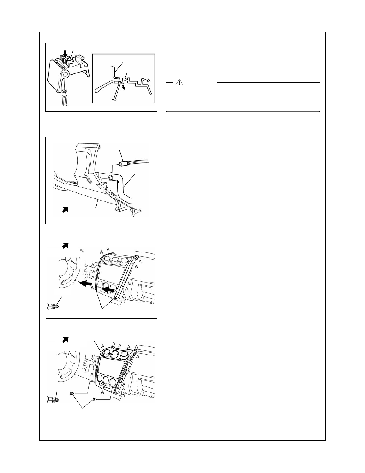
Hood release lever removal Note
a. Pull the lever.
b. While pushing the tab in the direction of the arrow using a
tape-wrapped, small flathead screwdriver, detach it from
the lower panel.
c. Under the condition in Step b, pull the hood release lever
outward, then remove it from the lower panel.
8. Remove the air hose and passenger’s compartment
temperature sensor connector.
9. Remove the lower panel.
Decoration panel removal
1. Detach clips A by pulling them in the direction of the arrow.
2. Remove the decoration panel.
Center panel removal
1. Remove the screws.
2. Pull the center panel outward and detach clips A.
3. Remove the center panel.
Tab
Lower panel (driver’s side)
Cross-sectional vie
w
Tab
•
Be careful not to damage the hood release cable when
removing the hood release lever with the flathead
screwdriver.
CAUTION
Connecto
r
Lower panel
Air hose
Vehicle front
Decoration panel
Clip A
Vehicle front
Flathead screwdriver
Center panel
Screws
Vehicle front
Clip A
 Loading...