

MAZATROL M PLUS Maintenance Manual
BNP-B201
7-1
41
(ENG)
MAZATROL
M
PLUS
Series
MAINTENANCE
MANUAL
(SYSTEM)
ADVANCED
AND
EVER
ADVANCING
MITSUBISHI
ELECTRIC
CONTENTS
Introduction
1
Chapter
1
Basic
Operations
for
Maintenance
1
.
Release
of
coded
key
lock
1-1
Prohibited
operations
.
1-2
Operations
for
releasing
key
lock
.
2.
Erasing
of
entire
memory
.
2-1
Cards
with
memory
mounted
2-2
Memory
clearing
operations
3.
Changing
of
option
parameters
3-1
Mounting
of
options
4.
Registering
and
reading
parameters
to
the
EEPROM
4-1
EEPROM
operation
format
.
4-2
Operations
for
registering
and
reading
parameters
to
the
EEPROM
5.
Backing
up
of
saved
data
5-1
Types
of
saved
data
5-2
Method
for
backing
up
saved
data
:
6.
File
system
configuration
6-1
File
system
format
7.
Setting
of
data
with
special
operations
7-1
Setting
of
calendar
and
timer
7-2
Setting
of
total
time
7-3
Changing
of
file
system
directory
8.
Initialization
of
data
8-1
Initialization
methods
2
2
2
3
4
4
4
5
9
10
10
10
11
11
11
12
12
14
14
14
15
16
16
Chaper
2
System
Maintenance
Work
1
.
Software
version
upgrade
2.
Addition
of
software
options
2-1
Addition
of
synchronous
tapping
option
.
2-2
Addition
of
48-digit
program
name
option
2-3
Addition
of
inch/metric
changeover
option
3.
Addition
of
large
capacity
memory
4.
Addition
of
communication
l/F
card
17
18
19
20
21
22
23
24
Introduction
This
manual
describes
the
work
and
various
operations
required
to
service
the
MAZATROL
Mplus.
We
hope
that
it
will
be
a
help
for
maintenance
work.
This
manual
focuses
only
on
the
MAZATROL
Mplus,
and
does
not
apply
to
other
systems.
Chapter
1
describes
the
various
operation
methods
required
for
the
work.
Additions
will
be
made
as
required.
Chapter
2
describes
the
actual
methods
of
main
work
anticipated
to
occur
during
maintenance.
Please
refer
to
the
Maintenance Manual
(Hardware)
BNP-B3869
when
replacing
the
card.
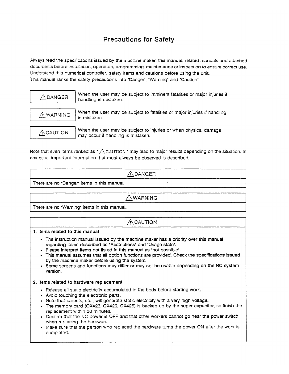
Precautions
for
Safety
Always
read
the
specifications
issued
by
the
machine
maker,
this
manual,
related
manuals
and
attached
documents
before
installation,
operation,
programming,
maintenance
or
inspection
to
ensure
correct
use.
Understand
this
numerical
controller,
safety
items
and
cautions
before
using
the
unit.
This
manual
ranks
the
safety
precautions
into
'Danger*,
'Warning*
and
'Caution*.
When
the
user
may
be
subject
to
imminent
fatalities
or
major
injuries
if
handling
is
mistaken.
DANGER
When
the
user
may
be
subject
to
fatalities
or
major
injuries
if
handling
is
mistaken.
WARNING
When
the
user
may
be
subjecttoinjuries
or
when
physical
damage
may
occur
if
handling
is
mistaken.
/j\
CAUTION
Note
that
even
items
ranked
as
*
'
may
lead
to
major
results
depending
on
the
situation.
In
any
case,
important
information
that
must
always
be
observed
is
described.
/j\DANGER
There
are
no
"Danger'
items
in
this
manual.
There
are
no
'Warning'
itemsinthis
manual.
1.
Items
relatedtothis
manual
•
The
instruction
manual
issuedbythe
machine
maker
has
a
priority
over
this
manual
regarding
items
described
as
'Restrictions'
and
'Usage
state'.
•
Please
interpret
items
not
listedinthis
manual
as
'not
possible'.
This
manual
assumes
that
all
option
functions
are
provided.
Check
the
specifications
issued
by
the
machine
maker
before
using
the
system.
•
Some
screens
and
functions
may
differ
or
may
not
be
usable
depending
on
the
NC
system
version.
2.
Items
relatedtohardware
replacement
•
Release
all
static
electricity
accumulated
in
the
body
before
starting
work.
•
Avoid
touching
the
electronic
parts.
•
Note
that
carpets,
etc.,
will
generate
static
electricity
with
a
very
high
voltage.
•
The
memory
card
(QX423,
QX429,
QX425)
is
backed
up
by
the
super
capacitor,
so
finish
the
replacement
within
30
minutes.
•
Confirm
that
the
NC
power
is
OFF
and
that
other
workers
cannot
go
near
the
power
switch
when
replacing
the
hardware.
•
Make
sure
that
the
person
who
replaced
the
hardware
turns
the
power
ON
after
the
work
is
completed.
3.
Items
related
to
preparing
for
maintenance
•
Always
set
the
'stored
stroke
limit*.
When
not
set,
the
machine
end
may
be
collided
into.
4.
Items
related
to
maintenance
work
•
Press
the
emergency
stop
button
before
starting
the
work.
If
the
button
has
to
be
released
to
confirm
the
operation,
make
sure
that
it
can
becsssed
immediately.
•
Do
not
let
unnecessary
workers
enter
the
area
w*en
opening
the
power
distribution
panel
door
and
servicing
the
system.
Chapter
1
Basic
Operations
for
Maintenance
1
Chapter
1
Basic
operations
for
maintenance
The
minimum
operations
required
for
servicing
the
system
are
described
in
this
chapter.
1.
Release
of
coded
key
lock
Functions
and
screens
that
are
net
used
by
the
user
are
locked
with
a
coded
key.
and
normally
cannot
oe
operated.
1-1
Prohibited
operations
©
Rewriting
of
system
parameters
•
According
to
following
HIDDEN
PARAMETER
screen.
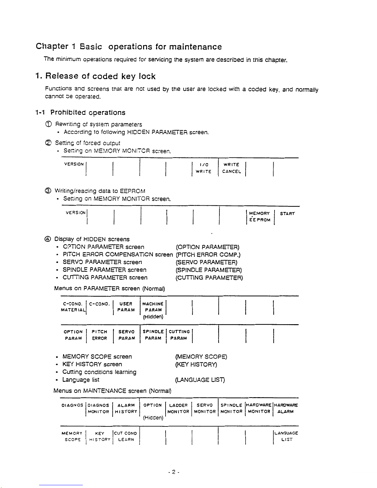
©
Setting
of
forced
output
•
Setting
on
MEMORY
MONITOR
screen.
VERSION
WRITE
CANCEL
I
/o
WRITE
©
Writing/reading
data
to
EEPROM
•
Setting
on
MEMORY
MONITOR
screen.
VERSION
MEMORY
E’EPROM
START
©
Display
of
HIDDEN
screens
•
OPTION
PARAMETER
screen
(OPTION
PARAMETER)
•
PITCH
ERROR
COMPENSATION
screen
(PITCH
ERROR
COMP.)
•
SERVO
PARAMETER
screen
(SERVO
PARAMETER)
(SPINDLE
PARAMETER)
(CUTTING
PARAMETER)
•
SPINDLE
PARAMETER
screen
•
CUTTING
PARAMETER
screen
Menus
on
PARAMETER
screen
(Normal)
USER
PARAM
MACHINE
PARAM
(Hidden)
C-CCNO.
MATERIAL
C-CONO.
SPINOLE
PARAM
CUTTING
PARAM
OPTION
PARAM
PITCH
ERROR
SERVO
PARAM
•
MEMORY
SCOPE
screen
•
KEY
HISTORY
screen
•
Cutting
conditions
learning
•
Language
list
Menus
on
MAINTENANCE
screen
(Normal)
(MEMORY
SCOPE)
(KEY
HISTORY)
(LANGUAGE
LIST)
SPINOLE
MONITOR
HARDWARE
MONITOR
HARO
WARE
ALARM
Dl
AGNOS
OPTION
LAOOER
MONITOR
SERVO
MONITOR
Dl
AGNOS
MONITOR
ALARM
HISTORY
(Hidden)
LANGUAGE
LIST
CUT
CONO
LEARN
MEMORY
SCOPE
KEY
HISTCRY
-
2
-

1-2
Operations
for
releasing
key
lock
The
key
lock
can
be
released
with
the
following
procedure.
The
released
key
is
held
until
the
power
is
turned
OFF,
and
will
automatically
be
re-locked
when
the
power
is
turned
ON
again.
©
Select
the
PARAMETER
screen
or
MAINTENANCE
screen.
©
Press
the
menu
selection
key,
and
then
input
j
1
|f
1
[[
3
][
1
||
INPUT
|
in
the
shown
order.
The
menu
of
the
HIDDEN
screen
will
appear
when
the
menu
selection
key
is
pressed.
](=ÿ
fan
i i
mn
i
i
Menu
keys
Menu
selection
key
Screen
selection
key
-
3
-
2.
Erasing
of
entire
memory
The
entire
memory
area
of
the
system
is
cleared
when
replacing
or
mounting
a
card
with
a
memory.
2-1
Cards
with
memory
mounted
©QX141
(CPU
card)
©
QX423,
429,
42S
(Standard
SRAM
and
large
capacity
memory)
•
Standard
SRAM
(QX423)
•
Large
capacity
memory
(QX423,
429,
425)
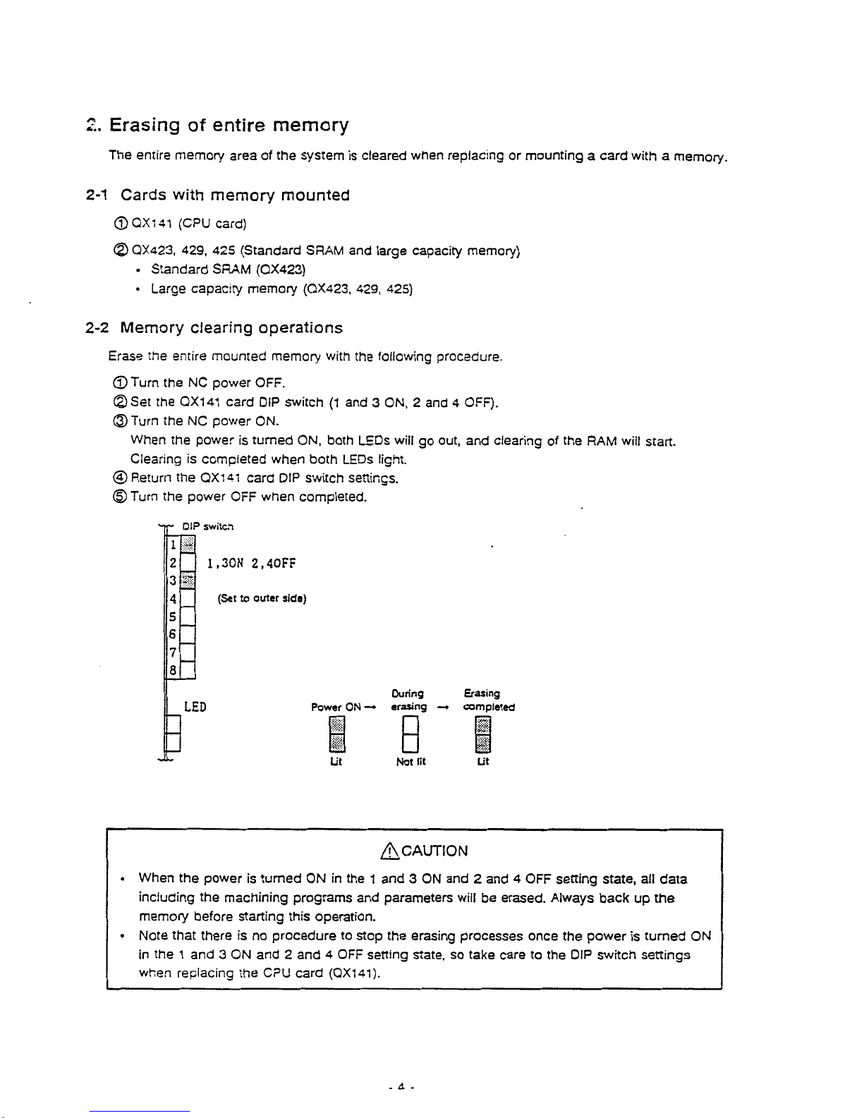
2-2
Memory
clearing
operations
Erase
the
entire
mounted
memory
with
the
following
procedure.
©Turn
the
NC
power
OFF.
©Set
the
QX141
card
DIP
switch
(1
and
3
ON,
2
and
4
OFF).
©Turn
the
NC
power
ON.
When
the
power
is
turned
ON,
both
LEDs
wilt
go
out,
and
clearing
of
the
RAM
will
start.
Clearing
is
completed
when
both
LEDs
light.
©Return
the
QX141
card
DIP
switch
settings.
©
Turn
the
power
OFF
when
completed.
'ip'
DIP
switcft
1
2
1.30N
2.40FF
3
4
(Set
to
outer
side)
5
6
7
8
During
Erasing
Power
ON
—
»
erasing
—
<
completed
LED
]
B
Ut
Not
lit
Ut
CAUTION
•
When
the
power
is
turned
ON
in
the
1
and
3
ON
and2and
4
OFF
setting
state,
all
data
including
the
machining
programs
and
parameters
will
be
erased.
Always
back
up
the
memory
before
starting
this
operation.
•
Note
that
there
is
no
procedure
to
stop
the
erasing
processes
once
the
power
is
turned
ON
in
the
1
and
3
ON
and
2
and
4
OFF
setting
state,
so
take
care
to
the
DIP
switch
settings
when
replacing
the
CPU
card
(0X141).
-
4
-
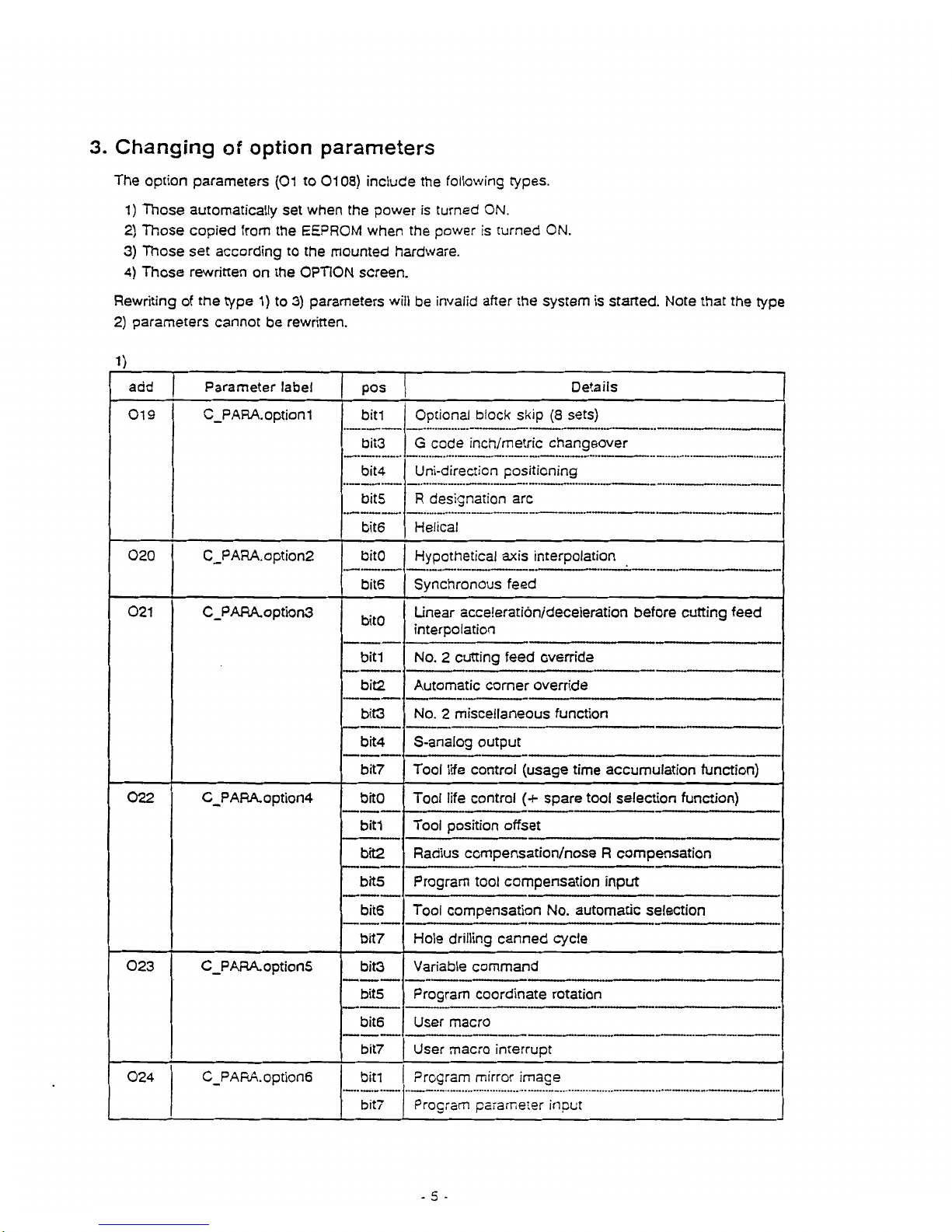
3.
Changing
of
option
parameters
The
option
parameters
(01
to
0108)
include
the
following
types.
1)
Those
automatically
set
when
the
power
is
turned
ON.
2)
Those
copied
from
the
EEPROM
when
the
power
is
turned
ON.
3)
Those
set
according
to
the
mounted
hardware.
4)
Those
rewritten
on
the
OPTION
screen.
Rewriting
of
the
type
1)to3)
parameters
will
be
invalid
after
the
system
is
started.
Note
that
the
type
2)
parameters
cannot
be
rewritten.
1)
Parameter
label
Details
add
pos
019
C_PARA.option1
Optional
block
skip
(8
sets)
bill
bit3
G
code
inch/metric
changeover
bit4
Uni-direction
positioning
bits
R
designation
arc
bit6
Helical
020
C_PARA.option2
bitO
Hypothetical
axis
interpolation
Synchronous
feed
bite
021
C_PARA.option3
Linear
acceleration/deceleration
before
cutting
feed
interpolation
bitO
bit1
No.
2
cutting
feed
override
bit2
Automatic
corner
override
bit3
No.2miscellaneous
function
bit4
S-analog
output
Tool
life
control
(usage
time
accumulation
function)
bit7
022
C_PARA.option4
Tool
life
control
(+
spare
tool
selection
function)
bitO
Tool
position
offset
bill
bit2
Radius
compensation/nose
R
compensation
Program
tool
compensation
input
bits
bite
Tool
compensation
No.
automatic
selection
Hole
drilling
canned
cycle
bit7
023
C_PARA.option5
Variable
command
bit3
bits
Program
coordinate
rotation
bit6
User
macro
User
macro
interrupt
bit7
024
C_PARA.option6
Program
mirror
image
bitl
Program
parameter
input
bit7
-5-
 Loading...