

Page 1
PROGRAMMING MANUAL
Return to Main Menu
for
MAZATROL MATRIX
(3-D UNIT)
MANUAL No. : H740PB0080E
Serial No. :
Before using this machine and equipment, fully understand the contents of this
manual to ensure proper operation. Should any questions arise, please ask the
nearest Technical Center or Technology Center.
IMPORTANT NOTICE
1. Be sure to observe the safety precautions described in this manual and the contents of the
safety plates on the machine and equipment. Failure may cause serious personal injury or
material damage. Please replace any missing safety plates as soon as possible.
2. No modifications are to be performed that will affect operation safety. If such modifications are
required, please contact the nearest Technical Center or Technology Center.
3. For the purpose of explaining the operation of the machine and equipment, some illustrations
may not include safety features such as covers, doors, etc. Before operation, make sure all
such items are in place.
4. This manual was considered complete and accurate at the time of publication, however, due to
our desire to constantly improve the quality and specification of all our products, it is subject to
change or modification. If you have any questions, please contact the nearest Technical Center
or Technology Center.
5. Always keep this manual near the machinery for immediate use.
6. If a new manual is required, please order from the nearest Technical Center or Technology
Center with the manual No. or the machine name, serial No. and manual name.
Issued by Manual Publication Section, Yamazaki Mazak Corporation, Japan
06. 2006
Page 2

Page 3

SAFETY PRECAUTIONS
Preface
Safety precautions relating to the CNC unit (in the remainder of this manual, referred to simply as
the NC unit) that is provided in this machine are explained below. Not only the persons who
create programs, but also those who operate the machine must thoroughly understand the
contents of this manual to ensure safe operation of the machine.
Read all these safety precautions, even if your NC model does not have the corresponding
functions or optional units and a part of the precautions do not apply.
Rule
1. This section contains the precautions to be observed as to the working methods and states
usually expected. Of course, however, unexpected operations and/or unexpected working
states may take place at the user site.
During daily operation of the machine, therefore, the user must pay extra careful attention to
its own working safety as well as to observe the precautions described bel ow.
2. Although this manual contains as great an amount of information as it can, since it is not
rare for the user to perform the operations that overstep the manufacturer-assumed ones,
not all of “what the user cannot perform” or “what the user must not perform” can be fully
covered in this manual with all such operations taken into consideration beforehand.
It is to be understood, therefore, that functions not clearly written as “executable” are
“inexecutable” functions.
SAFETY PRECAUTIONS
3. The meanings of our safety precautions to DANGER, WARNING, and CAUTION are as
follows:
: Failure to follow these instructions could result in loss of life.
DANGER
: Failure to observe these instructions could result in serious harm to a human
life or body.
WARNING
: Failure to observe these instructions could result in minor injuries or serious
machine damage.
CAUTION
HGENPA0042E
S-1
Page 4
Basics
SAFETY PRECAUTIONS
! After turning power on, keep hands away from the keys, buttons, or switches of the
operating panel until an initial display has been made.
WARNING
! Before proceeding to the next operations, fully check that correct data has been entered
and/or set. If the operator performs operations without being aware of data errors,
unexpected operation of the machine will result.
! Before machining workpieces, perform operational tests and make sure that the machine
operates correctly. No workpieces must be machined without confirmation of normal
operation. Closely check the accuracy of programs by executing override, single-block, and
other functions or by operating the machine at no load. Also, fully utilize tool path check,
Virtual Machining, and other functions, if provided.
! Make sure that the appropriate feed rate and rotational speed are designated for the
particular machining requirements. Always understand that since the maximum usable fee d
rate and rotational speed are determined by the specifications of the tool to be used, those
of the workpiece to be machined, and various other factors, actual capabilities differ from
the machine specifications listed in this manual. If an inappropriate feed rate or rotational
speed is designated, the workpiece or the tool may abruptly move out from the machine.
! Before executing correction functions, fully check that the direction and amount of
correction are correct. Unexpected operation of the machine will result if a correction
function is executed without its thorough understanding.
! Parameters are set to the optimum standard machining conditions prior to shipping of the
machine from the factory. In principle, these settings should not be modified. If it becomes
absolutely necessary to modify the settings, perform modifications only after thoroughly
understanding the functions of the corresponding parameters. Modifications usually affect
any program. Unexpected operation of the machine will result if the settings are modified
without a thorough understanding.
Remarks on the cutting conditions recommended by the NC
! Before using the following cutting conditions:
- Cutting conditions that are the result of the MAZATROL Automatic Cutting Conditions
WARNING
Determination Function
- Cutting conditions suggested by the Machining Navigation Function
- Cutting conditions for tools that are suggested to be used by the Machining Navigation
Function
Confirm that every necessary precaution in regards to safe machine setup has been taken –
especially for workpiece fixturing/clamping and tool setup.
! Confirm that the machine door is securely closed before starting machining.
Failure to confirm safe machine setup may result in serious injury or death.
S-2
Page 5

Programming
WARNING
SAFETY PRECAUTIONS
! Fully check that the settings of the coordinate systems are correct. Even if the designated
program data is correct, errors in the system settings may cause the machine to operate in
unexpected places and the workpiece to abruptly move out from the machine in the event
of contact with the tool.
! During surface velocity hold control, as the current workpiece coordinates of the surface
velocity hold control axes approach zeroes, the spindle speed increases significantly. For
the lathe, the workpiece may even come off if the chucking force decreases. Safety speed
limits must therefore be observed when designating spindle speeds.
! Even after inch/metric system selection, the units of the programs, tool information, or
parameters that have been registered until that time are not converted. Fully check these
data units before operating the machine. If the machine is operated without checks being
performed, even existing correct programs may cause the machine to operate differently
from the way it did before.
! If a program is executed that includes the absolute data commands and relative data
commands taken in the reverse of their original meaning, totally unexpected operation of
the machine will result. Recheck the command scheme before executing programs.
! If an incorrect plane selection command is issued for a machine action such as arc
interpolation or fixed-cycle machining, the tool may collide with the workpiece or part of the
machine since the motions of the control axes assumed and those of actual ones will be
interchanged. (This precaution applies only to NC units provided with EIA functions.)
! The mirror image, if made valid, changes subsequent machine actions significantly. Use
the mirror image function only after thoroughly understanding the above. (This precaution
applies only to NC units provided with EIA functions.)
! If machine coordinate system commands or reference position returning commands are
issued with a correction function remaining made valid, correction may become invalid
temporarily. If this is not thoroughly understood, the machine may appear as if it would
operate against the expectations of the operator. Execute the above commands only after
making the corresponding correction function invalid. (This precaution applies only to NC
units provided with EIA functions.)
! The barrier function performs interference checks based on designated tool data. Enter the
tool information that matches the tools to be actually used. Otherwise, the barrier function
will not work correctly.
! The system of G-code and M-code commands differs, especially for turning, between the
machines of INTEGREX e-Series and the other turning machines.
Issuance of the wrong G-code or M-code command results in totally non-intended machine
operation. Thoroughly understand the system of G-code and M-code commands before
using this system.
Sample program Machines of INTEGREX e-Series Turning machines
S1000M3
S1000M203
The milling spindle rotates at 1000 min–1. The turning spindle rotates at 1000 min–1.
The turning spindle rotates at 1000 min–1. The milling spindle rotates at 1000 min–1.
S-3
Page 6
SAFETY PRECAUTIONS
! For the machines of INTEGREX e-Series, programmed coordinates can be rotated using
an index unit of the MAZATROL program and a G68 command (coordinate rotate command) of the EIA program. However, for example, when the B-axis is rotated through 180
degrees around the Y-axis to implement machining with the turning spindle No. 2, the plus
side of the X-axis in the programmed coordinate system faces downward and if the
program is created ignoring this fact, the resulting movement of the tool to unexpected
positions may incite collisions.
To create the program with the plus side of the X-axis oriented in an upward direction, use
the mirror function of the WPC shift unit or the mirror imaging function of G-code command
(G50.1, G51.1).
! After modifying the tool data specified in the program, be sure to perform the tool path
check function, the Virtual Machining function, and other functions, and confirm that the
program operates properly. The modification of tool data may cause even a field-proven
machining program to change in operational status.
If the user operates the machine without being aware of any changes in program status,
interference with the workpiece could arise from unexpected operation.
For example, if the cutting edge of the tool during the start of automatic operation is present
inside the clearance-including blank (unmachined workpiece) specified in the common unit
of the MAZATROL program, care is required since the tool will directly move from that
position to the approach point because of no obstructions being judged to be present on
this path.
For this reason, before starting automatic operation, make sure that the cutting edge of the
tool during the start of automatic operation is present outside the clearance-including
workpiece specified in the common unit of the MAZATROL program.
CAUTION
! If axis-by-axis independent positioning is selected and simultaneously rapid feed selected
for each axis, movements to the ending point will not usually become linear. Before using
these functions, therefore, make sure that no obstructions are present on the path.
S-4
Page 7
Operations
WARNING
SAFETY PRECAUTIONS
! Single-block, feed hold, and override functions can be made invalid using system variables
#3003 and #3004. Execution of this means the important modification that makes the
corresponding operations invalid. Before using these variables, therefore, give thorough
notification to related persons. Also, the operator must check the settings of the system
variables before starting the above operations.
! If manual intervention during automatic operation, machine locking, the mirror image
function, or other functions are executed, the workpiece coordinate systems will usually be
shifted. When making machine restart after manual intervention, machine locking, the
mirror image function, or other functions, consider the resulting amounts of shift and take
the appropriate measures. If operation is restarted without any appropriate measures being
taken, collision with the tool or workpiece may occur.
! Use the dry run function to check the machine for normal operation at no load. Since the
feed rate at this time becomes a dry run rate different from the program-designated feed
rate, the axes may move at a feed rate higher than the programmed value.
! After operation has been stopped temporarily and insertion, deletion, updating, or other
commands executed for the active program, unexpected operation of the machine may
result if that program is restarted. No such commands should, in principle, be issued fo r the
active program.
CAUTION
! During manual operation, fully check the directions and speeds of axial movement.
! For a machine that requires manual homing, perform manual homing operations after
turning power on. Since the software-controlled stroke limits will remain ineffective until
manual homing is completed, the machine will not stop even if it oversteps the limit area.
As a result, serious machine damage will result.
! Do not designate an incorrect pulse multiplier when performing manual pulse handle feed
operations. If the multiplier is set to 1000 times and the handle operated inadvertently, axial
movement will become faster than that expected.
S-5
Page 8

BEFORE USING THE NC UNIT
BEFORE USING THE NC UNIT
Limited Warranty
The warranty of the manufacturer does not cover any trouble arising if the NC unit is used for its
non-intended purpose. Take notice of this when operating the unit.
Examples of the trouble arising if the NC unit is used for its non-intended purpose are listed
below.
1. Trouble associated with and caused by the use of any commercially available software
products (including user-created ones)
2. Trouble associated with and caused by the use of any Windows operating systems
3. Trouble associated with and caused by the use of any commercially available computer
equipment
Operating Environment
1. Ambient temperature
During machine operation: 0° to 50°C (32° to 122°F)
2. Relative humidity
During machine operation: 10 to 75% (without bedewing)
Note: As humidity increases, insulation deteriorates causing electrical component parts to
deteriorate quickly.
Keeping the Backup Data
Note: Do not attempt to delete or modify the data stored in the following folder.
Recovery Data Storage Folder: D:\MazakBackUp
Although this folder is not used when the NC unit is running normally, it contains important data
that enables the prompt recovery of the machine if it fails.
If this data has been deleted or modified, the NC unit may require a long recovery time. Be sure
not to modify or delete this data.
S-6
E
Page 9

CONTENTS
Page
1 INTRODUCTION.................................................................................. 1-1
2 GENERAL............................................................................................. 2-1
2-1 General...............................................................................................................2-1
2-2 Creation of Curved-Surface Figures...................................................................2-1
2-3 Movement of a Constant Curved Line................................................................2-2
2-4 Changing Conditions of a Curved Line...............................................................2-2
2-5 3-D Machining Units and Types of Curved Surfaces Created............................2-3
3 PROGRAMMING.................................................................................. 3-1
3-1 Program Configuration .......................................................................................3-1
3-2 Before Programming ..........................................................................................3-1
3-3 Programs for 3-D Machining Units......................................................................3-2
3-3-1 Unit definition.......................................................................................................... 3-3
3-3-2 Tool-sequence definition......................................................................................... 3-7
3-3-3 Plane definition.....................................................................................................3-12
3-3-4 Figure definition....................................................................................................3-16
3-3-5 Coordinate transfer............................................................................................... 3-20
3-3-6 Machining area appointment ................................................................................ 3-22
4 PROGRAMMING EXAMPLES ............................................................. 4-1
4-1 ROTATE 1..........................................................................................................4-1
4-2 ROTATE 2..........................................................................................................4-4
4-3 ROTATE 3..........................................................................................................4-6
C-1
Page 10

4-4 ROTATE 4..........................................................................................................4-8
4-5 PARALL. 1........................................................................................................4-10
4-5-1 Tool movement and precautions .......................................................................... 4-12
4-6 PARALL. 2........................................................................................................4-14
4-7 PARALL. 3........................................................................................................4-16
4-8 PARALL. 4........................................................................................................4-18
4-9 NORMAL 1.......................................................................................................4-20
4-9-1 Coordinate axes for defining FL in NORMAL units............................................... 4-22
4-10 NORMAL 2.......................................................................................................4-26
4-11 Ruled Surface...................................................................................................4-28
4-12 ROTATE 1 + Coordinate Transfer....................................................................4-30
4-13 Combination Program (Example 1) ..................................................................4-32
4-14 Combination Program (Example 2) ..................................................................4-35
5 RELATIVE PARAMETERS................................................................... 5-1
C-2
E
Page 11

1 INTRODUCTION
Three-dimensional machining functions are automatic programming functions used for 3dimensional curved-surface machining which presents difficulties for line- or face-machining
programs.
Automatic programming functions in the easy-to-understand MAZATROL language (human
language) enable 3-dimensional curved surfaces to be machined by performing simple
operations.
This Programming Manual describes the programming procedures for machining 3-D curved
surfaces with the MAZATROL MATRIX.
Read through this manual carefully in order to make the most of the 3-D machining functions
available with the MAZATROL MATRIX.
In addition to this manual, reference should also be made to the Programming Manual and the
Operating Manual.
INTRODUCTION 1
1-1
Page 12

1 INTRODUCTION
- NOTE -
1-2
E
Page 13

2 GENERAL
2-1 General
The 3-dimensional machining functions enable 3-dimensional curved surfaces, which are difficult
to machine with line- or face-machining programs, to be handled with relative ease.
Programs with a greater degree of flexibility can be prepared when these functions are used in
conjunction with the line- and face-machining units.
The features of these 3-D machining functions are listed below:
1. Easy-to-understand MAZATROL language
Programming uses the MAZATROL language which allows programs to be created with the
same kind of ease which characterizes ordinary MAZATROL programs. As a result, 3-D
programming, which presented difficulties before, can now be handled with ease.
2. Simple representation of curved surfaces
Wire-frame models that can be defined with figure lines and guide lines are used so that the
3-dimensional curved surfaces can be set as easily as possible. In addition, GL (guide line)
and FL (figure line) figures can be input using methods similar to those for line- or facemachining.
GENERAL 2
3. Creation of wide variety of curved surfaces
A wide variety of complex curved surfaces can be handled by selecting any of the 11 types
of units in accordance with the curved surface to be machined.
4. Automatic determination of tool paths for rough machining and finish machining
Simply by defining the final curved-surface figures, the tool paths for both rough machining
and finish machining can be determined automatically.
5. Outstanding graphic check functions
Not merely the tool path and trace display but also the defined curved-surface figures can
be displayed in wire-frame format, and this makes it easier to understand and check the
defined curved-surface figures.
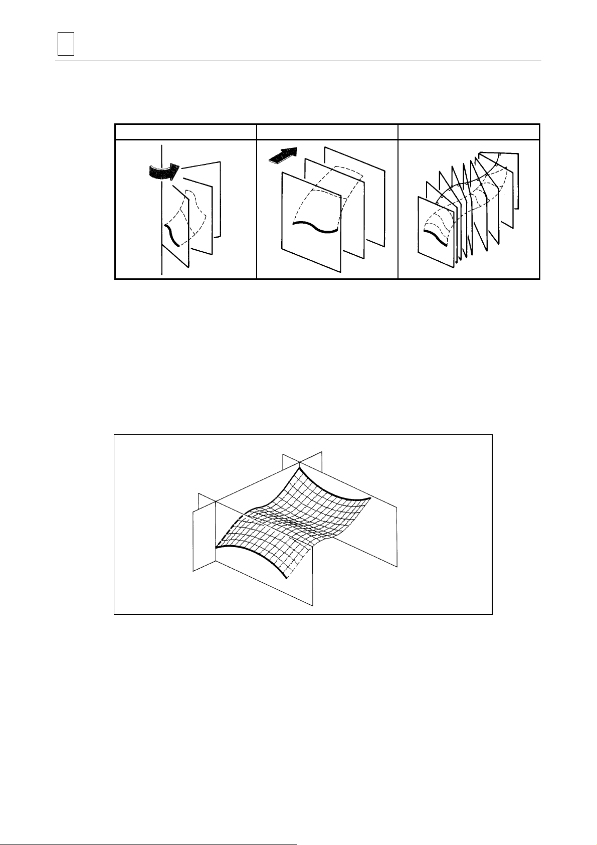
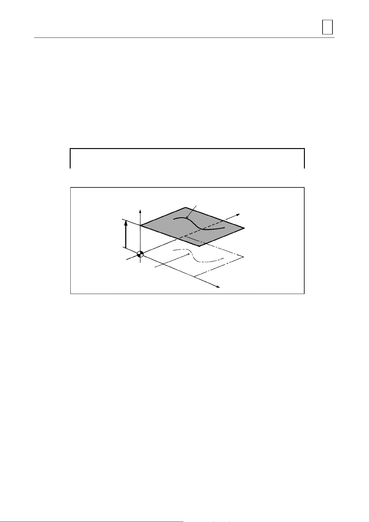
2-2 Creation of Curved-Surface Figures
A curved surface is formed when a curved line on a given plane is moved through 3-dimensional
space.
A variety of curved-surface figures can be created by defining the following conditions.
- Movement of a constant curved line
- Movement of a changing curved line
The curved-surface figures thus defined are then shaped with a 3-D machining unit.
2-1
Page 14
2 GENERAL
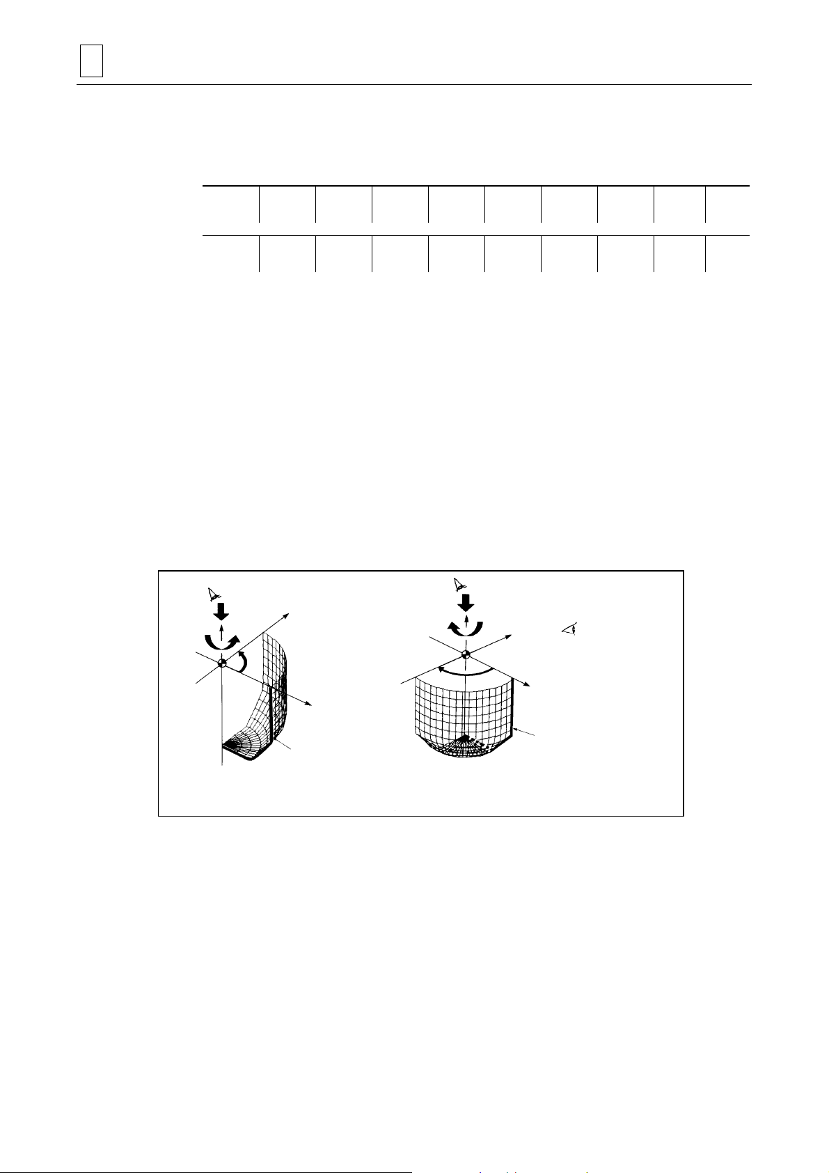
2-3 Movement of a Constant Curved Line
The movement of a curved line through 3-dimentional space is restricted to the following.
Rotation Parallel displacement Normal displacement
Furthermore, a curved-surface figure can be created by smoothly connecting a multiple number
of curved lines on given planes within 3-dimensional space (ruled surface).
2-4 Changing Conditions of a Curved Line
A curved line that is moved through 3-dimensional space is referred to as the FL (figure line).
Usually, one FL is defined as the starting curved line or two FLs are defined as the starting and
ending curved lines. A GL (guide line) which is used to guide the defined FL is also defined.
The desired curved-surface figure is created by moving and changing the starting figure line
(FL1) into the ending figure line (FL2) according to the above conditions and the guid e line (GL).
GL
FL1
FL2
D735P0500
2-2
Page 15
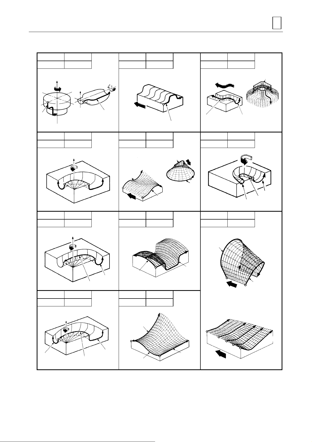
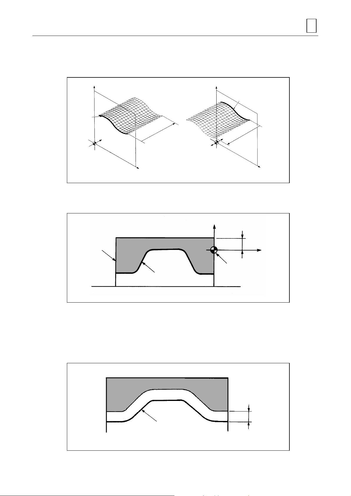
2-5 3-D Machining Units and Types of Curved Surfaces Created
UNIT ROTATE 1 UNIT PARALL.1 UNIT NORMAL 1
GL-FL 0-1 GL-FL 0-1 GL-FL 1-1
GENERAL 2
Z
Z
FL1
UNIT ROTATE 2 UNIT PARALL.2 UNIT NORMAL 2
GL-FL 0-2 GL-FL 0-2 GL-FL 1-2
Z
FL2
UNIT ROTATE 3 UNIT PARALL.3 UNIT RULED-S
GL-FL 1-1 GL-FL 1-1 GL-FL 0-20
FL1
(Applied type)
FL1
GL
FL1
FL1
FL2
FL2
FL1
FL
FL2
GL
FL
FL1
GL
Z
FL1
GL
UNIT ROTATE 4 UNIT PARALL.4
GL-FL 1-2 GL-FL 1-2
Z
FL2
GL
FL1
GL
FL2
GL
FL1
FL1
FL2
FL5
FL4
FL1
FL3
FL2
FL1
2-3
Page 16

2 GENERAL
- NOTE -
2-4
E
Page 17

3 PROGRAMMING
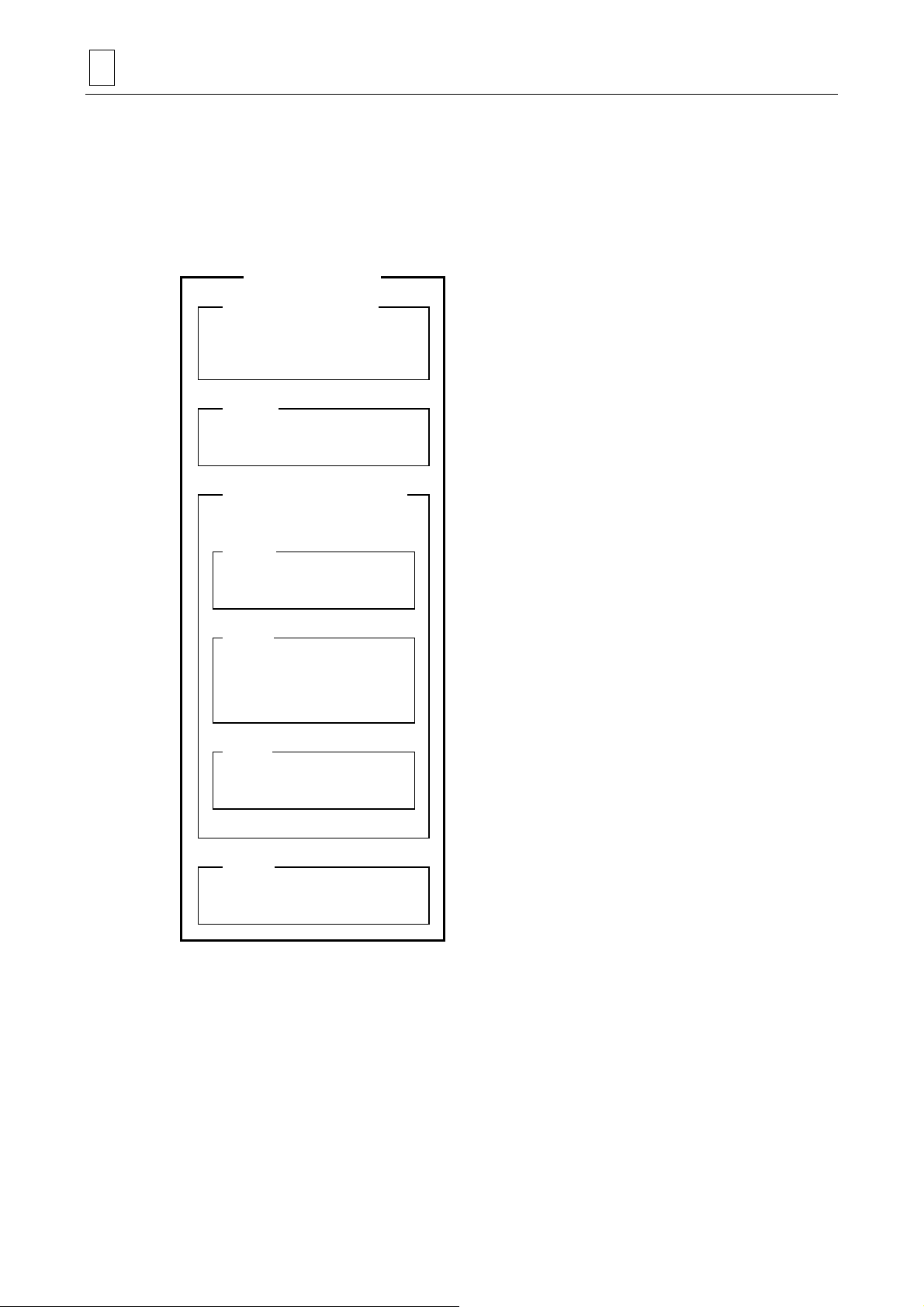
3-1 Program Configuration
The 3-D machining units are handled in exactly the same manner as the point-, line-, and facemachining units. A 3-D program is therefore composed basically of the following 4 program units.
The 3-D machining unit can also be used with the point-, line-, and/or face-machining units.
Program
Common unit
Basic coordinate system unit
Machining unit
- Point-machining unit
- Line-machining unit
- Face-machining unit
- 3-D machining unit
PROGRAMMING 3
..........This unit is always set at the head of all
programs.
..........The basic coordinates of the workpiece zero point
in the machine coordinate system are specified
here.
.......... The machining methods and data relating to the
figures to be machined are specified here.
The 3-D unit can also be specified in addition to
point-, line-, and face-machining units.
By specifying a plurality of machining units, the
workpiece will be machined to the desired shape.
End unit
3-2 Before Programming
Programming is done by following the same pro ce du res as those prescrib ed for point-, line-, and
face-machining.
For details on the methods for creating and editing programs, reference should be made to the
Programming Manual (MAZATROL).
..........This unit is set at the end of all programs.
3-1
Page 18
3 PROGRAMMING
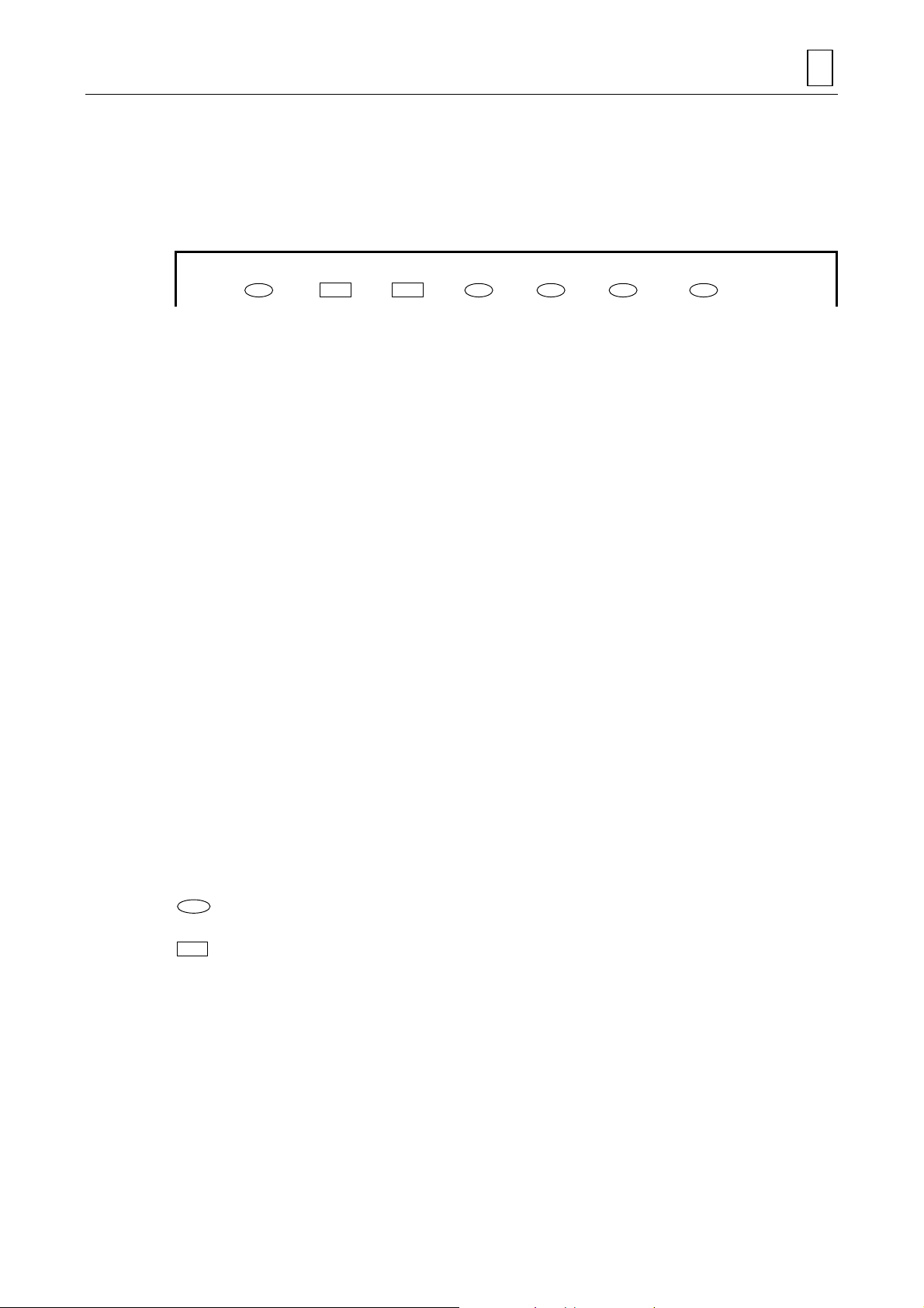
3-3 Programs for 3-D Machining Units
A 3-D machining units consist of unit definition, tool-sequence definition, curved-surface
definition and machining area appointment. The curved-surface definition is subdivided into 3
parts: plane definition (definition of the plane on which curved lines are placed), figure definition
and coordinate transfer.
3D machining unit
UNo. (Unit definition)
SNo.
(Tool-sequence definition)
Curved-surface definition
PLN
(Plane definition)
.......... Select from among the 11 types of units that unit
by which it will be easiest to define the desired
shape.
.......... The tool operating conditions are set with these
data.
.......... The data relating to the machining methods and
shapes of the curved-surfaces are set here.
..........The plane for defining the figure is set here.
FIG
(Figure definition)
TRN
(Coordinate transfer)
CSF
(Machining area appointment)
..........The GL (guide line) and FLs (figure lines) are
input here to create the curved-surface shape for
machining.
..........Data are input here to move or rotate the created
curved surface to any position.
..........The machining area for the created curved
surface is specified here.
3-2
Page 19
3-3-1 Unit definition
The unit definition inputs the data required to automatically determine the tool sequence for 3-D
machining. The tools required for machining are automatically determined by inputting the types
of the units, FL movements/angles, material height, finishing allowance, and cutting processes.
These data are invalid once the tool sequence has been displayed.
UNo. UNIT GL-FL ROT.AXIS DIST/th. MAT-HIGH FIN CUT-PROCESS
[1] [2] [3] [4] [5] [6] [7]
[1] UNIT
Select the menu item in accordance with the machining method.
Input example: [ROTATE 1] → ROTATE 1 unit is set.
[2] GL-FL
The numbers of GLs/FLs used in this unit are displayed.
Display example: 1-1 → One GL and one FL are used.
[3] ROT. AXIS
“Z” is displayed as the rotational axis for GL-FL when one of the [ROTATE 1] through
[ROTATE 4] menu items has been selected for UNIT.
Display example: Z → Denotes that the rotational axis is Z.
PROGRAMMING 3
[4] DIST/th.
Input the values for setting the parallel movement distance of FL or its angle of rotation.
Input example: 30 → 30 mm movement or rotation by 30° in the positive direction
[5] MAT-HIGH
Input a numerical value to set the height of the material from the workpiece zero point.
Input example: 50 → Material height of 50 mm
[6] FIN
Input a numerical value to set the section to be left uncut as a finishing allowance while
rough machining is performed.
Input example: 2 → Finishing allowance of 2 mm
[7] CUT-PROCESS
Select a cutting process and rough machining method from among the menu items.
Input example: [ROUGH R1] → Rough machining only
denotes either items which can be selected from the menu or items for which numerical
values are input.
denotes items which are automatically displayed.
Reference should be made to the following description for details on items [1] through [7].
3-3
Page 20
3 PROGRAMMING
1. UNIT
The unit name selected from the menu is displayed. The following 11 types are available as 3-D
machining units.
Menu 1
Menu 2
ROTATE1ROTATE2ROTATE3ROTATE4PARALLEL1PARALLEL2PARALLEL3PARALLEL4>>>
NORMAL1NORMAL2RULED-S. >>>
2. GL-FL
The number of GLs (guide lines) and FLs (figure lines) is displayed as soon as the unit name
appears.
3. ROT. AXIS
“Z” is displayed as the rotational axis when rotation unit name from among ROTATE 1 through
ROTATE 4 is displayed
4. DIST/th.
Set the angle through which the FL (figure line) is to be rotated in order to create a curved
surface when ROTATE 1 or ROTATE 2 has been selected. (As seen from the +Z direction, the
selected FL rotates counterclockwise or clockwise if a positive or negative value is entered,
respectively.)
+Z
th
CCW
(th.: positive value)
+Y
FL
+X
+Z
th
CW
(th.: neg at i ve value)
+Y
: Direction in which
the angle is to be
read
+X
FL
D735P0501
3-4
Page 21
PROGRAMMING 3
Set the distance through which the FL (figure line) is to be moved in parallel in order to create a
curved surface when either the PARALL. 1 or PARALL. 2 unit has been selected. (The selected
FL moves in parallel in the + (plus) direction if a positive value is entered and in the – (minus)
direction if a negative value is entered.)
+Z+Z
FL
FL
DIST
–Y
Workpiece
zero point
+Y
(Positive value)
–Y
Workpiece
zero point
+Y
(Negative value)
DIST
When a positive
value is set
When a negative
value is set
+X+X
D735P0502
5. MAT-HIGH
Set the height from the workpiece zero point on the Z-axis to the top of the material.
+Z
Material
Curved-surface figure
MAT-HIGH
+X
Workpiece zero point
D735P0503
Note: A negative value cannot be used to set the material height. The workpiece zero point
must therefore be set in the minus direction (in other words, below) from the top of the
material.
6. FIN
Set the finishing allowance for the section to be left uncut by rough machining.
Rough machining
Fini sh machining
Curved-surface figure
3-5
FIN
D735P0504
Page 22

3 PROGRAMMING
7. CUT-PROCESS
Select the cutting process from the following menu as well as whether rough machining is to be
performed at high speed or at normal speed.
The data selected here are used to select the tools in the tool sequence.
(The data become invalid once the tool sequence has been displayed.)
ROUGHR1RGH,FIN1
R1-F2
Menu Cutting process Tool selected
ROUGH R1 Rough machining R1: BAL EMIL
RGH, FIN1 R1-F1 Rough machining → Finishing 1
RGH, FIN2 R1-F2-F3
FINISH 1 F1 Finishing 1 F1: BAL EMIL
FINISH 2 F1-F2 Finishing 1 → Finishing 2
RGH,FIN2
R1-F2-F3
Rough machining → Finishing 1→
Finishing 2
FINISH 1F1FINISH 2
F1-F2
H SPEED
RGH PRC.
R1: BAL EMIL
F2: BAL EMIL
R1: BAL EMIL
F2: BAL EMIL
F3: BAL EMIL
F1: BAL EMIL
F2: BAL EMIL
If the rough machining process is selected after reversing the display state of the menu item by
pressing the [H SPEED RGH PRC.] menu key, the rough machining tool in the tool sequence will
be displayed as below:
R1 END MILL
In this case, rough machining will be performed at high speed.
High-speed rough machining can be identified by observing whether or not the tool sequence “R”
appears in red.
High-speed rou gh ma chining
Normal-speed machinin g
D735P0505
3-6
Page 23

3-3-2 Tool-sequence definition
The tools to be used are automatically determined by the unit definition.
A tool is made operational by defining such factors as its normal diameter, approach coordinates,
peripheral speed and feed rate.
SNo. TOOL NOM-φ No. APRCH-X APRCH-Y TYPE DEPTH #T PITCH C-SP FR M M M
[1] [2] [3] [4] [4] [5] [6] [7] [8] [9] [9] [10][10][10]
[1] TOOL
The tool is automatically determined according to the CUT-PROCESS data set during unit
definition.
[2] NOM-φ
Input a numerical value to set the diameter of the tool. Select a suffix from the menu if
necessary.
[3] No.
Input a numerical value to set the operation priority number when the pri ority function for the
same tool is to be used.
PROGRAMMING 3
[4] APRCH-X, APRCH-Y
Input numerical values or press the [AUTO SET] menu key to set the coordinates which the
tool will initially approach.
Input example: [AUTO SET] → “?” is displayed and the values are determined
automatically upon checking the tool path.
[5] TYPE
Select the cutting type from the menu.
Input example: [X BI-DIR] → X-axis bi-directional rough machining
[6] DEPTH
For rough machining, input the numerical value to set the depth for one cutting pass in an
axial direction.
Input example: 5 → Cutting to a depth of 5 mm
For finish machining, input the numerical value to set the amount to be left uncut as the
finishing allowance.
Input example: 2 → 2 mm is left as the finishing allowance.
[7] #T
Input the desired machining error tolerance level for the curved-surface figure using a
number from 1 to 9.
Input example: 1 → Parameter E67 for machining error tolerance level is used.
[8] PITCH
Input a numerical value to set the desired pitch for cutting.
Input example: 10 → Cutting is performed by a pitch of 10 mm.
[9] C-SP, FR
Input numerical values to set the C-SP (peripheral speed) and FR (feed rate).
Input example: C-SP: 500 → Peripheral speed of 500 mm/min
FR: 50 → Feed rate of 50 mm/rev
3-7
Page 24

3 PROGRAMMING
10
]M
[
Reference should be made to the following description for details on items [1] through [
1. TOOL
The tool is automatically selected according to the data set during the cutting process selection
for unit definition.
BAL EMIL (ball-end mill) is used for 3-D machining but END MILL (ordinary end mill) is used for
high-speed rough machining.
2. NOM-φ
Use a value for the tool diameter so that it can be distinguished from the diametrical values of
other tools (0.1 mm). Assign a suffix (identification code A to Z) (except I and O) from the menu
to identify identical tools.
Select from the menu the M-code to be output immediately after the tool has been
automatically changed (ATC).
Input example: [50 AIR BLAST] → Air blasting operation
denotes either items which can be selected from the menu or items for which numerical
values are input.
denotes items which are automatically displayed.
10
].
Note: The tool defined here must be registered on the TOOL FILE display beforehand.
3. No.
Set the operation priority number when the priority function for the same tool is to be used.
1) Operation to be done first (1 to 99)
2) No number
3) Operation to be done later (1 to 99)
(During machining the tools are selected in the order of 1 to 3.)
For further details reference should be made to “PRIORITY FUNCTION FOR THE SAME TOOL”
in the Programming Manual (MAZATROL Programming).
4. APRCH-X, APRCH-Y
Set the coordinates to which the tool is to be approached initially after completing ATC
(automatic tool changing). If the [AUTO SET] menu key is pressed, “?” is displayed and the
coordinates are automatically calculated and set when the tool path is checked.
3-8
Page 25

PROGRAMMING 3
5. TYPE
Select the cutting type from the menu.
For high-speed rough machining
Select one of the following menu items depending on whether the tool is to be fed bi-directionally
or uni-directionally in parallel with the X-axis or Y-axis.
X
BI-DIRYBI-DIRXUNI-DIRYUNI-DIR
X BI-DIR X UNI-DIR
Y BI-DIR Y UNI-DIR
Rapid traverse Cutting feed AP: Approach point
WRK SIZE
DESIGN.
Also select whether high-speed rough machining is to be performed with offset appointment or
workpiece-size appointment. Offset appointment is set when the [WORK SIZE DESIGN.] menu
item is displayed normal; workpiece-size appointment is set when the item is displayed in
reverse form. The display will change alternately each time the menu key is pressed.
Offset appointment Workp i ec e- si ze appoi n tment
E83
Y
X
Z
X
The bold codes represent the parameter addresses.
Material height
E88
E85
Y
X
Z
X
Curved-surface
figure
E86
E87
Material height
D735P0506
Note: Workpiece-size appointment has been provided principally for male figures. It can also
be made effective for female figures by changing the parameters. (Normally, highly
efficient operations can be undertaken through combinations with line- and facemachining.)
3-9
Page 26

3 PROGRAMMING
For cases other than rough machining
Select from the following menu whether bi-directional or uni-directional machining is to be
performed in parallel with or at right angles to the FL (figure line).
6. DEPTH
UNI-DIR
//-1
UNI-DIR
-1
UNI-DIR / /-1 BI-DIR / /-2
UNI-DIR -1 BI-DIR -2
BI-DIR
//-2
BI-DIR
-2
For rough machining
Set the depth to which the workpiece is to be machined per cutting pass in an axial direction.
Example:
DEPTH
Material height
Curved-surface figure
D735P0507
For finish machining
Set the finishing allowance for the section left uncut when machining with finishing tools.
Example:
Material height
Rough machining
FIN
(unit definition)
Fini sh machining 1
Fini sh machining 2
Curved-surface figure
3-10
DEPTH DEPTH
(F2) (F1)
(Remaining allowance)
D735P0508
Page 27

PROGRAMMING 3
T
7. #T
Set the tolerance level of the machining for the curved-surface figure using a number from 1 to 9.
The tolerance levels corresponding to number 1 through 9 have been set in parameters
E75.
Example:
Curved-surface
figure
#
#T
8. PITCH
Set the cutting pitch amount (pick feed).
Example:
PITCH
AP
E67 to
D735P0509
D735P0510
9. C-SP, FR
Set the cutting conditions. An automatic setting function is not available with this setting.
10. M
Set the M-code that is to be output immediately after the tool has been automatically changed
(ATC).
3-11
Page 28

3 PROGRAMMING
3-3-3 Plane definition
In order to define the GL (guide line) and FLs (figure lines) in 3-dimensional space, set the
positional relationship of the plane containing the GL and FLs to the workpiece zero point.
PLN LINE PLANE DISTANCE ROT.-X ROT.-Y ROT.-Z SHIFT-X SHIFT-Y SHIFT-Z
[1] [2] [3] [4] [4] [4] [5] [5] [5]
[1] LINE
The display indicates whether the line to be set is a GL or FL.
Display example: GL → Line to be set is GL.
[2] PLANE
Select from the menu the plane which will serve as the reference for placing the curved
lines.
Input example: X-Y → X-Y plane
[3] DISTANCE
Input a numerical value to set the distance between the plane containing the curved line and
the workpiece zero point.
Input example: 50 → The plane is set 50 mm away from the workpiece zero point.
[4] ROT.-X, ROT.-Y, ROT.-Z
Input a numerical values to set the angle of inclination for the plane containing the curved
line.
Input example: ROT.-X: 30 → +30° rotation around the X-axis
ROT.-Y: 10 → +10° rotation around the Y-axis
ROT.-Z: 0 → No rotation around the Z-axis
Note: The sequence of axes around which the plane rotates is X, Y, and Z.
[5] SHIFT-X, SHIFT-Y, SHIFT-Z
Input a numerical values to set the distance between the plane containing the curved line
and the reference plane.
Input example: SHIFT-X: 50 → Shifting 50 mm in the X-axis positive direction
SHIFT-Y: 20 → Shifting 20 mm in the Y-axis positive direction
SHIFT-Z: 0 → No shifting in the Z-axis direction
Note: The sequence of axes along which the plane moves is X, Y, and Z.
denotes either items which can be selected from the menu or items for which numerical
values are input.
denotes items which are automatically displayed.
3-12
Page 29

PROGRAMMING 3
Y
Reference should be made to the following description for details on items [1] through [5].
The various patterns for plane definition (PLN) which depend on the types of units involved are
summarized in the following table.
GL (guide line) FL (figure line)
Number
of FIGs
ROTATE 1 0 0 — 1 1 X-Z
ROTATE 2 0 0 — 2 1 X-Z
ROTATE 3 1 1 X-Y 1 0 —
ROTATE 4 1 1 X-Y 2 0 —
PARALL. 1 0 0 — 1 1 X-Y, X-Z, Y-Z
PARALL. 2 0 0 — 2 1 X-Y, X-Z, Y-Z
PARALL. 3 1 1 X-Y, X-Z, Y-Z 1 0 X-Y, X-Z, Y-Z
PARALL. 4 1 1 X-Y, X-Z, Y-Z 2 0 X-Y, X-Z, Y-Z
NORMAL 1 1 1 X-Y, X-Z, Y-Z 1 0 —
NORMAL 2 1 1 X-Y, X-Z, Y-Z 2 0 —
RULED-S 0 0 — Max. 20 Max. 20 X-Y, X-Z, Y-Z
Number
of PLNs
Appointed plane
Number
of FIGs
Number of
PLNs
Appointed plane
Note: Several planes are defined for RULED-S. Each time a definition is completed, press
the
[FL DEFINE] menu key and define the next plane.
1. LINE
The GL or FL is displayed depending on the type of unit selected.
This item indicates whether the curved line to be placed on the plane defined here is a GL or FL.
2. PLANE
Appoint an X-Z plane (FL) for ROTATE 1 or ROTATE 2 and an X-Y plane (GL) for ROTATE 3 or
ROTATE 4.
- For the other units in the table, select the corresponding menu item for the plane which will
serve as the reference for placing the curved line. The curved lines are defined on this
reference plane. When the actual curved lines are not present on this plane, designate the
plane by rotation (in [4]) or shifting (in [5]).
- The positional relationship of the planes and the observation points for reading their
coordinates are shown in the figure.
+Z
Y-Z
X-Z
Observation point
when viewing Xplane
+Y
Observation point when
viewing X-Z plane
Workpiece
zero point
X-Y
+X
Observation point
when viewing Y-Z
plane
D735P0511
3-13
Page 30

3 PROGRAMMING
A
g
3. DISTANCE
Set the distance from the plane containing the curved line to the workpiece zero point by e ntering
the coordinate value of the axis passing at right angles through the plane.
PLN LINE PLANE DISTANCE ROT.-X ROT.-Y ROT.-Z SHIFT-X SHIFT-Y SHIFT-Z
Given below is the figure which illustrates this example.
FLX-Z50000000
+Z
Figure difined by
shape sequence
50 (DISTANCE)
+X
+Y
FL
(Figure line shifted in
accordance wi th DISTANCE)
D735P0512
The X-Z plane moves in the Y-axis direction. (In this case, the reference plane moves 50 mm in
the positive direction.)
Note: These distance data have the same significance as those of SHIFT-X, SHIFT-Y and
SHIFT-Z (in [5]). This can be better understood by first setting 0 as the DISTANCE data
and then moving the plane in parallel using the
SHIFT-X/Y/Z.
4. ROT.-X, ROT.-Y, ROT.-Z
Set the angle of inclination of the plane containing the curved line with respect to the base plane
as the angle of rotation around the axis in question. In accordance with this angle, the reference
plane rotates around the designated axis as its center. (Set 0 for an axis around which no
rotation is intended.)
PLN LINE PLANE DISTANCE ROT.-X ROT.-Y ROT.-Z SHIFT-X SHIFT-Y SHIFT-Z
FLX-Y03000000
Given below is the figure which illustrates this example.
+Z
Figure defined with
shape sequence
+X
+Y
FL
(Figure line rotated 30°
according to ROT)
for readin
bservation point
angel
D735P0513
3-14
Page 31
PROGRAMMING 3
In this case, the reference plane rotates 30° counterclockwise (po sitive value) a round the X-axis.
Note 1: The rotational direction around each axis must be designated with a positive value for
counterclockwise rotation when viewed from the positive (+) side of the rotating axis.
For clockwise rotation, set a negative value.
Note 2: If rotational angles are set for a multiple number of axes, the reference plane will rotate
around the axes in the order of X, Y and Z.
5. SHIFT-X, SHIFT-Y, SHIFT-Z
Set the distance between the plane containing the curved line and the reference plane.
The reference plane now moves in parallel with the specified axis. (Set 0 for an axis along which
no movement is intended.)
PLN LINE PLANE DISTANCE ROT.-X ROT.-Y ROT.-Z SHIFT-X SHIFT-Y SHIFT-Z
FLX-Y00000020
Given below is the figure which illustrates this example.
FL
+Z
(Figure line shifted in accordance with SHIFT)
+Y
(Shift amount in
Z-axis direction)
20
Figure defined with
shape sequence
+X
D735P0513
In this case, the reference plane moves 20 mm along the Z-axis in the positive direction.
Note: When the shift amounts are set for a multiple number of axes, the reference plane will
move along in the sequence of the X-, Y- and Z-axes. When both the distance and
rotation data are set in addition to the shift data, the reference plane will move and
rotate in the same order as that displayed (distance, rotation, shift).
3-15
Page 32

3 PROGRAMMING
3-3-4 Figure definition
This defines GL (guide line) and FL (figure line) curved-line figures. The definition method is the
same as that for line- and face-machining. For details, reference should be made to “Shape
sequence data of the line machining and face machining units” in the Programming Manual
(MAZATROL Programming).
<Arbitrary form>
FIG PTN X Y R/th. I J P CNR
<Fixed form>
FIG PTN P1X/CX P1Y/CY P3X/R P3Y CN1 CN2 CN3 CN4
Definitions of arbitrary forms are all handled as open forms. The shape sequence items for the
X-Y plane are always displayed, even if a plane containing a figure is selected as X-Z or Y-Z. The
following table shows the relationship between the reference planes and actual title axes for
sequence data.
Plane Form Actual shape sequence title
X-Y
X-Z
X-Z
Arbitrary form
Fixed form
Arbitrary form
Fixed form
Arbitrary form
Fixed form
FIG PTN X Y R/th I J P CNR
FIG PTN P1X/CX P1Y/CY P3X/R P3Y CN1 CN2 CN3 CN4
FIG PTN X Z R/th I K P CNR
FIG PTN P1X/CX P1Z/CZ P3X/R P3Z CN1 CN2 CN3 CN4
FIG PTN Y Z R/th J K P CNR
FIG PTN P1Y/CY P1Z/CZ P3Y/R P3Z CN1 CN2 CN3 CN4
The number of shapes and the setting sequence differ depending on the type of unit.
Press the [SHAPE END] menu key to complete the setting of a curved-surface shape in a shape
sequence.
When defining a multiple number of curved lines in a single shape sequence, select the
[STARTING POINT] menu item at the head of the figure definition before defining them.
When defining a multiple number of planes and setting the shape sequence in one unit (ruled-
surface), press the [SHAPE END] menu key to complete the setting.
The menu will now change as follows.
[COORDIN. TRANSFER], [FL DEFINE] or [3-D END] can be selected from this menu.
COORDIN.
TRANSFER
FL
DEFINE
3-D
END
Note: When defining an arbitrary form in the figure definition, press the [SHAPE END] menu
key on the arbitrary form menu and then press the [SHAPE END] menu key on the
figure definition menu.
Reference should be made to “3-3-5 Coordinate transfer” for further details on this menu.
3-16
Page 33

PROGRAMMING 3
The tables below show the various sequences for defining a GL (guide line) and FL1 and FL2
(figure lines) in each unit.
ROTATE 1
PLN LINE PLANE
FL X-Z
FIG PTN
LINE
1
2
CW
3
CCW
ROTATE 2
PLN LINE PLANE
FL X-Z
FIG PTN
LINE
1
CW
2
CCW
3
LINE
4
CW
5
CCW
6
ROTATE 3
PLN LINE PLANE
GL X-Y
FIG PTN
LINE
1
CW
2
CCW
3
LINE
4
CW
5
CCW
6
ROTATE 4
PLN LINE PLANE
GL X-Y
FIG PTN
LINE
1
2
CW
3
CCW
LINE
4
CW
5
CCW
6
LINE
7
CW
8
CCW
9
…
…
FL1
…
…
FL1
FL2
…
…
GL
FL1
…
…
GL
FL1
FL2
denotes the starting point of a curved line.
After setting FL1, reverse the menu display by pressing the
[STARTING POINT] menu key and then press the [LINE]
menu key to input the FL2 shape.
After setting GL, reverse the menu display by pressing the
[STARTING POINT] menu key and then press the [LINE]
menu key to input the FL1 shape.
After setting GL, reverse the menu display by pressing the
[STARTING POINT] menu key and then press the [LINE]
menu key to input the FL1 shape.
After setting FL1, reverse the menu display by pressing the
[STARTING POINT] menu key and then press the [LINE]
menu key to input the FL2 shape.
3-17
Page 34

3 PROGRAMMING
PARALL. 1
PLN LINE PLANE …
FL X-Z
FIG PTN …
1
LINE
2
CW
3
CCW
FL1
PARALL. 2
PLN LINE PLANE …
FL X-Z
FIG PTN …
1
LINE
2
CW
3
CCW
4
LINE
5
CW
6
CCW
FL1
FL2
PARALL. 3
PLN LINE PLANE …
GL X-Y
FIG PTN …
1
LINE
2
CW
3
CCW
PLN LINE PLANE …
FL Y-Z
FIG PTN …
4
LINE
5
CW
6
CCW
GL
FL1
PARALL. 4
PLN LINE PLANE …
GL X-Y
FIG PTN …
1
LINE
2
CW
3
CCW
PLN LINE PLANE …
FL Y-Z
FIG PTN …
4
LINE
5
CW
6
CCW
7
LINE
8
CW
9
CCW
GL
FL1
FL2
denotes the starting point of a curved line.
After setting FL1, reverse the menu display by pressing the
[STARTING POINT] menu key and then press the [LINE]
menu key to input the FL2 shape.
After setting GL, press the [SHAPE END] menu key and
then press the
[SHAPE END] menu key on the shape
definition menu and finally select the plane for defining FL.
After setting GL, press the [SHAPE END] menu key and
then press the
[SHAPE END] menu key on the shape
definition menu and finally select the plane for defining FL.
After setting FL1, reverse the menu display by pressing the
[STARTING POINT] menu key and then press the [LINE]
menu key to input the FL2 shape.
3-18
Page 35

PROGRAMMING 3
NORMAL 1
PLN LINE PLANE …
GL X-Y
FIG PTN …
1
LINE
2
CW
3
CCW
4
LINE
5
CW
6
CCW
GL
FL1
NORMAL 2
PLN LINE PLANE …
GL X-Y
FIG PTN …
1
LINE
2
CW
3
CCW
4
LINE
5
CW
6
CCW
7
LINE
8
CW
9
CCW
GL
FL1
FL2
RELED-S
PLN LINE PLANE …
FL X-Y
FIG PTN …
1
LINE
2
CW
3
CCW
PLN LINE PLANE …
FL X-Y
FIG PTN …
1
LINE
2
CW
3
CCW
PLN LINE PLANE …
FL X-Y
FIG PTN …
1
LINE
2
CW
3
CCW
:
:
:
FL1
FL2
FL3
:
:
:
:
denotes the starting point of a curved line.
After setting GL, reverse the menu display by pressing the
[STARTING POINT] menu key and then press the [LINE]
menu key to input the FL1 shape.
After setting GL, reverse the menu display by pressing the
[STARTING POINT] menu key and then press the [LINE]
menu key to input the FL1 shape.
After setting FL1, reverse the menu display by pressing the
[STARTING POINT] menu key and then press the [LINE]
menu key to input the FL2 shape.
After setting FL1, press the [SHAPE END] menu key and
then press the
[SHAPE END] menu key on the figure
definition menu and finally select the plane for defining FL2.
After setting FL2, press the [SHAPE END] menu key and
then press the
[SHAPE END] menu key on the figure
definition menu and finally select the plane for defining FL3.
3-19
Page 36

3 PROGRAMMING
3-3-5 Coordinate transfer
The menu will change as follows upon completion of the figure definition.
COORDIN.
TRANSFER
FL
DEFINE
3-D
END
Press the [COORDIN. TRANSFER] menu key to set the coordinate transfer mode.
Press the
Press the
[FL DEFINE] menu key to define the FL (figure line) for RULED-S.
[3-D END] menu key to move to the next program operation (machining area
appointment).
Coordinate transfer
The curved surfaces (whole figure) created by plane definition and figure definition can be shifted
to any position in 3-dimensional space by using rotation or parallel displacement.
TRN PTN ROT.-X ROT.-Y ROT.-Z SHIFT-X SHIFT-Y SHIFT-Z
SURF-MOVE
[1] [1] [1] [2] [2] [2]
[1] ROT.-X, ROT.-Y, ROT.-Z
Input the numerical values to set the angle through which the created curved surface as a
whole is to be rotated. Input 0 for an axis around which no rotation is intended.
Input example: ROT.-X: 30 → 30° counterclockwise rotation around the X-axis
ROT.-Y: –10 → 10° clockwise rotation around the Y-axis
ROT.-Z: 0 → No rotation around the Z-axis
Note: The sequence of axes around which the curved surface rotates is X, Y, and Z.
[2] SHIFT-X, SHIFT-Y, SHIFT-Z
Input the numerical values to set the distance through which the created curved surface as
a whole is to be shifted. Input 0 for axes for which no movement is intended.
Input example: SHIFT-X: 50 → Shifting 50 mm in the X-axis positive (+) direction
SHIFT-Y: 20 → Shifting 20 mm in the Y-axis positive (+) direction
SHIFT-Z: 0 → No shifting for Z-axis direction
Note: The sequence of axes along which the curved surface moves is X, Y and Z.
denotes items for which numerical values are input.
Reference should be made to the following description for details on items [1] and [2].
1. ROT.-X, ROT.-Y, ROT.-Z
Set the angle of rotation for the axes around which the entire created surface is to be rotated.
(Input 0 for an axis around which no rotation is intended.)
Example:
TRN PTN ROT.-X ROT.-Y ROT.-Z SHIFT-X SHIFT-Y SHIFT-Z
SURF-MOVE 90 0 0 0 0 0
3-20
Page 37

PROGRAMMING 3
Given below is the figure which illustrates this example.
+Z
+Y
°
90
+X
D735P0514
In this case, the curved surface is rotated 90° counterclockwise (positive value) around the Xaxis.
Note 1: The rotational direction around each axis must be designated with a positive value for
counterclockwise rotation when viewed from the positive (+) side of the rotating axis.
For clockwise rotation, set a negative value.
Note 2: If rotational angles are set for a multiple number of axes, the sequence of axes around
which the curved surface rotates is X, Y, and Z.
2. SHIFT-X, SHIFT-Y, SHIFT-Z
Set the distance through which the entire created curved surface is to be shifted along the
particular axis.
(Set 0 for an axis along which no shift is intended.)
Example:
TRN PTN ROT.-X ROT.-Y ROT.-Z SHIFT-X SHIFT-Y SHIFT-Z
SURF-MOVE 0 0 0 0 0 -30
Given below is the figure which illustrates this example.
+Z
+Y
30 mm
+X
D735P0515
In this case, the curved surface is shifted 30 mm in the minus (–) direction along the Z-axis.
Note: When the shift amounts are set for a multiple number of axes, the sequence of axes for
the shift is X, Y, and Z. When both rotation and shift amounts are set, rotation is
performed first (according to the order on the display).
3-21
Page 38

3 PROGRAMMING
3-3-6 Machining area appointment
The machining area for the defined curved surface i s set he re. All data items mu st be left blank if
the entire curved surface is to be set as the machining area.
CSF PTN X-MIN X-MAX Y-MIN Y-MAX Z-MIN Z-MAX IN/OUT
AREA
[1] [1] [1] [1] [2] [2] [3]
[1] X-MIN, X-MAX, Y-MIN, Y-MAX
Input the numerical values to set the machining area in the X-axis and in the Y-axis
directions.
Input example:
X-MIN: 0, X-MAX: 500
→ Machining is performed over an area from 0 to 500 mm in the X-axis direction.
Y-MIN: 0, Y-MAX: 250
→ Machining is performed over an area from 0 to 250 mm in the Y-axis direction.
[2] Z-MIN, Z-MAX
Input the numerical values to set the machining area in the Z-axis direction.
Input example:
Z-MIN: 100, Z-MAX: blank
→ Machining is performed over an area from 100 mm to infinity in the Z-axis direction.
[3] IN/OUT
On the menu select whether machining is to be undertaken inside or outside the area
indicated by MIN and MAX for each axis.
Input example: [IN THE AREA] → Machining is performed over an area between MIN
and MAX.
denotes either items which can be selected from the menu or items for which numerical
values are input.
Reference should be made to the following description for details on items [1] and [2].
3-22
Page 39

1. X-MIN, X-MAX, Y-MIN, Y-MAX (IN/OUT)
X
Set machining areas in the X- and Y-axis directions.
PROGRAMMING 3
Curved-surface figure
Curved-surface figure
+X
: Machining are a
when IN is selected
at IN/OUT
: Machining are a
when OUT is
selected at IN/OUT
+X
D735P0516
Workpiece zero point
Y-MA
Y-MIN
Workpiece zero point
+Y
X-MIN X-MAX
+Y
X-MIN X-MAX
Note 1: If all the data items are left blank, the machining area is treated as infinite. Also, IN is
considered valid for IN/OUT.
X-MAX, Y-MAX → –∞
X-MIN, Y-MIN→ +∞
Note 2: As the machining area is appointed on the basis of pitch, there may be times when an
area smaller than 1 pitch is left uncut.
Note 3: A finishing allowance is added for the roughing tool.
2. Z-MIN, Z-MAX (IN/OUT)
Set the machining area in the Z-axis direction.
: Machining are a
There is no
distinction between
IN and OUT; IN is
always selected.
+X
Z-MAX
Z-MIN
Workpiece
zero point
+Z
Curved-surface figure
Note: If all the data items are left blank, the machining area is treated as infinite.
Z-MIN → –∞
Z-MAX → +∞
D735P0517
3-23
Page 40

3 PROGRAMMING
- NOTE -
3-24
E
Page 41
4 PROGRAMMING EXAMPLES
A’A
A
–
X
–
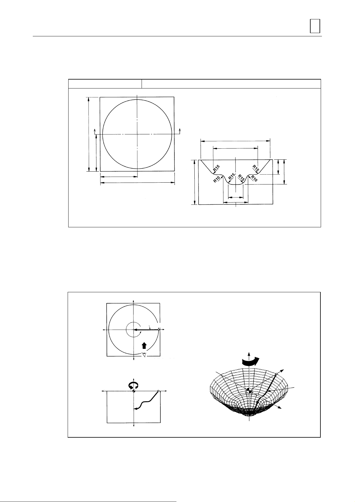
4-1 ROTATE 1
Programming example 1 ROTATE 1
PROGRAMMING EXAMPLES 4
Unit: mm
150
75
75
150
90
View in direction of A-
140
90
30
50
30
50
’
1) Definition of the plane
Define the FL (figure line) on the X-Z plane containing the workpiece zero point (WPC).
2) Creation of the curved surface
Rotate the X-Z plane (+ side) on which the FL (figure line) has been defined around the Zaxis of the workpiece coordinate system.
Set the rotational angle to 360°.
+Y
D735P0518
–X
360°
rotation
FL
Viewing point for
–Y
defining FL
+Z
–Z
Starting
FL
Starting point
+X
point
+X
4-1
+Y
+Z
Counterclockwise
rotation
+X
FL
Y
D735P0519
Page 42

4 PROGRAMMING EXAMPLES
Y
Program
UNo. UNIT GL-FL ROT.AXIS DIST/th. MAT-HIGH FIN CUT-PROCESS
1 ROTATE 1 0-1 Z 360. 0. 2. R1-F2
[4] [5] [6]
[1] [3]
SNo. TOOL NOM-φ No. APRCH-X APRCH-Y TYPE DEPTH #T PITCH C-SP FR M M M
R1 BAL EMIL 20.A ? ? -1 5. 5 5. 200 0.25
F2 BAL EMIL 20.A ? ? -1 0. 5 5. 250 0.25
[2]
PLN LINE PLANE DISTANCE ROT.-X ROT.-Y ROT.-Z SHIFT-X SHIFT-Y SHIFT-Z
FL X-Z !!!0. !!!
FIG PTN X Y R/th I J P CNR
1 LINE 70. 0.
2 LINE 45. -30. R15.
3 LINE 25. -30. R10.
4 LINE 15. -50. R15.
5 LINE 0. -50.
CSF PTN X-MIN X-MAX Y-MIN Y-MAX Z-MIN Z-MAX IN/OUT
AREA
[1] DIST/th.
This indicates the amount of rotation from the starting plane for machining to the ending
plane of machining.
Incremental angle th
(–360 ≤ th2 ≤360) is to be set.
2
[2] ROT.-Z
The position of the starting plane for machining is to be defined by setting angle th
X-axis.
from the
1
Creatio n of figur e
th
and th2: Angles as seen from
1
plus (+) side of the Z-axis
CW: Clockwise rotation
(negative value)
CCW: Counterclockwise rotation
(positive value)
FL
th
= DIST/th
2
= ROT.-Z
th
1
X
D735P0520
[3] MAT-HIGH
The distance from the workpiece zero point on the Z-axis to the top of the stock material is
to be set.
MAT-HIGH
WPC-Z = 0
D735P0521
4-2
Page 43

PROGRAMMING EXAMPLES 4
[4] TYPE
The type of machining is to be set.
-1 indicates right-angular and uni-directional tool movement (the tool is to be fed at right
angles to the figure line in one direction only).
Tool moves at right
angles to the figure line.
Tool
FL
Tool path
D735P0522
/ /-1 indicates parallel and uni-directional tool movement (the tool is to be fed in parallel with
the figure line in one direction only).
Tool path
Tool
FL
D735P0523
[5] #T
The desired level of tolerance is to be set. (The amount of tolerance is to be set on the
PARAMETER display.)
[6] PITCH
The amount of pick feed is to be set.
The pitch between the tool paths is to be set.
PITCH
PITCH
FL
D735P0524
4-3
Page 44

4 PROGRAMMING EXAMPLES
–
X
g
4-2 ROTATE 2
Programming example 2 ROTATE 2
150
60
60
75 60
Unit: mm
60
75
150
1) Definition of the plane
Define FL1 and FL2 (figure lines) on the X-Z plane containing the workpiece zero point
(WPC).
2) Creation of the curved surface
Rotate the X-Z plane (+ side) around the Z-axis of the workpiece coordinate system so that
FL1 and FL2 can be connected smoothly.
Set the rotational angle to 90°.
+Y
Viewing point for defining FL2
FL2
90° rotation
+Z
FL1
–X
+Z
FL1
Starting
point
FL1
–Y
Viewing point for
FL1
definin
+X
+X
Counterclockwise
rotation
+Y
D735P0525
+X
FL2
–Z
FL2
D735P0526
4-4
Page 45

PROGRAMMING EXAMPLES 4
Program
[1] [4]
UNo. UNIT GL-FL ROT.AXIS DIST/th. MAT-HIGH FIN CUT-PROCESS
1 ROTATE 2 0-2 Z 90. 0. 5. R1-F2-F3
SNo. TOOL NOM-φ No. APRCH-X APRCH-Y TYPE DEPTH #T PITCH C-SP FR M M M
R1 END MILL 10.A ? ? XUN 5. 5 5. 200 0.25
F2 BAL EMIL 20.A ? ? -1 2. 5 5. 200 0.25
F3 BAL EMIL 20.A ? ? -1 0. 2 2. 250 0.25
PLN LINE PLANE DISTANCE ROT.-X ROT.-Y ROT.-Z SHIFT-X SHIFT-Y SHIFT-Z
FL X-Z !!!0 !!!
FIG PTN X Y R/th I J P CNR
1 LINE 40. 0.
[2]
2 CCW 80. 0. 20. ?(60.) ?(0.)
3 LINE 20. 0.
[3]
4 CCW 100. 0. 40. ?(60.) ?(0.)
CSF PTN X-MIN X-MAX Y-MIN Y-MAX Z-MIN Z-MAX IN/OUT
AREA
[1] GL-FL
This indicates the number of GLs (guide lines) and FLs (figure lines) used to define the
curved surfaces.
Two FLs (figure lines) are to be defined with the ROTATE 2 unit.
[2] FIG (FL1)
The first defined figure line becomes the figure line on the starting plane for machining
(FL1).
[3] FIG (FL2)
The second defined figure line becomes the figure line on the ending plane for machining
(FL2).
Press the [STARTING POINT] menu key before defining FL2.
[4] CUT-PROCESS
The high-speed machining mode is to be set.
Press the [H SPEED RGH PRC.] menu key to select the desired cutting process.
4-5
Page 46

4 PROGRAMMING EXAMPLES
–
–
4-3 ROTATE 3
Programming example 3 ROTATE 3
Unit: mm
200
160
80
75
35
50
50
130
200
1) Definition of the plane
Define FL (figure line) on the X-Z plane containing the workpiece zero point (WPC) and
define GL (guide line) on the X-Y plane containing the workpiece zero point.
2) Creation of the curved surface
Define FL on the X-Z plane containing the workpiece zero point. In this case, the zero point
of FL is used as the starting point for GL.
The figure line (FL) defined on the X-Z plane is rotated around the Z-axis of the workpiece
coordinate system along the guide line (GL).
+Y
D735P0527
FL creates the curved surface
when rot at e d along G L.
GL
GL
+Z
FL
+X
D735P0528
X
Starting
–Y
point
Starting point for GL and
+Z
programming zero pont for FL
X
FL
Viewing po in t for
defining FL
FL
+X
+Y
+X
4-6
Page 47

PROGRAMMING EXAMPLES 4
Program
[1]
UNo. UNIT GL-FL ROT.AXIS DIST/th. MAT-HIGH FIN CUT-PROCESS
1 ROTATE 3 1-1 Z ! 40. 5. R1-F2
[4]
SNo. TOOL NOM-φ No. APRCH-X APRCH-Y TYPE DEPTH #T PITCH C-SP FR M M M
R1 END MILL 20.A ? ? XUN 5. 5 5. 200 0.25
F2 BAL EMIL 10.A ? ? -1 0. 2 2. 250 0.25
[5]
PLN LINE PLANE DISTANCE ROT.-X ROT.-Y ROT.-Z SHIFT-X SHIFT-Y SHIFT-Z
GL X-Y 0. 0. 0. 0. 0. 0. 0.
FIG PTN X Y R/th I J P CNR
1 LINE 50. 0.
2 LINE 50. 50. R10.
[2]
3 LINE 0. 80.
5 LINE 0. 0.
6 CCW 10. 10. 10. ? (0.) ?(10.)
[3]
7 CW 70. 10. 30. ?(40.) ?(10.)
8 CCW 80. 0. 10. ?(80.) ?(10.)
CSF PTN X-MIN X-MAX Y-MIN Y-MAX Z-MIN Z-MAX IN/OUT
AREA
[1] GL-FL
This indicates the number of guide lines (GLs) and figure lines (FLs) used to define the
curved surfaces.
One guide line (GL) and one figure line (FL) are defined with the ROTATE 3 unit.
[2] FIG (GL)
The first defined curved line becomes the guide line (GL) on the X-Y plane defined in the
plane definition.
[3] FIG (FL)
The second defined curved line becomes the figure line (FL) o n the X-Z plane containing the
workpiece zero point.
In this case, the program zero point of FL is used as the starting point of GL.
[4] TYPE
“Uni-directional X” is to be set in the workpiece size appointment.
The parameters E85, E86, E87, and E88 are to be set to 0, 70, 0, and 40, respectively, as
the material dimensions.
[5] PLANE
The X-Y plane is to be set for ROTATE 3.
4-7
Page 48

4 PROGRAMMING EXAMPLES
–
X
–
–
Y
4-4 ROTATE 4
Programming example 4 ROTATE 4
150
150
95
65
110
50
40
30
50
90
130
130
110
90
Unit: mm
1) Definition of the plane
Define FL1 and FL2 (figure lines) on the X-Z plane containing the workpiece zero point
(WPC) and define GL (guide line) on the X-Y plane containing the workpie c e zero point.
D735P0529
2) Creation of the curved surface
The figure line (FL1) defined on the X-Z plane is rotated around the Z-axis of the workpiece
coordinate system along the guide line (GL) with continuou s modifi cation to end smo othly in
the second figure line (FL2).
The starting and ending points of GL must be used as the zero points of FL1 and FL2,
respectively.
+Y
Viewing point for defining FL2
FL2
X
GL
Starting point
for GL
+Z
The starting point for FL1 and FL2 are
the staring and ending points for GL.
FL1
Smooth cr e at ion of a curved
surface from FL1 to FL2
FL1
Viewing point for defining FL1
+X
+X
+Z
GL
+Y
FL2
+X
FL1
FL2
–Z
D735P0530
4-8
Page 49

PROGRAMMING EXAMPLES 4
Program
[1]
UNo. UNIT GL-FL ROT.AXIS DIST/th. MAT-HIGH FIN CUT-PROCESS
1 ROTATE 4 1-2 Z ! 0. 1. R1-F2
SNo. TOOL NOM- φ No. APRCH-X APRCH-Y TYPE DEPTH #T PITCH C-SP FR M M M
R1 BAL EMIL 20.A ? ? -1 5. 5 5. 200 0.25
F2 BAL EMIL 20.A ? ? -1 0. 2 2. 250 0.25
PLN LINE PLANE DISTANCE ROT.-X ROT.-Y ROT.-Z SHIFT-X SHIFT-Y SHIFT-Z
GL X-Y 0. 0. 0. 0. 0. 0. 0.
FIG PTN X Y R/th I J P CNR
1 LINE 90. 0.
2 LINE 50. 40. R10.
[2]
3 LINE 0. 50.
4 LINE 0. 0.
[3]
5 CCW 40. 0. 20. 20. 0.
6 LINE 0. 0.
7 LINE 15. -30. R11.
[4]
8 LINE 30. -30. R11.
9 LINE 60. 0.
CSF PTN X-MIN X-MAX Y-MIN Y-MAX Z-MIN Z-MAX IN/OUT
AREA
[1] GL-FL
This indicates the number of guide lines (GLs) and figure lines (FLs) used to define the
curved surfaces.
One guide line (GL) and two figure lines (FL1 and FL2) are defined with the ROTATE 4 unit.
[2] FIG (GL)
The first defined curved line becomes the guide line (GL) on the X-Y plane defined in the
plane definition.
[3] FIG (FL1)
The second defined curved line becomes the figure line (FL1) on the X-Z plane containing
the workpiece zero point.
In this case, the program zero point of FL1 is used as the starting point of GL.
[4] FIG (FL2)
The third defined curved line becomes the figure line (FL2) on the X-Z plane containing the
workpiece zero point.
In this case, the program zero point of FL2 is used as the ending point of GL.
Note: The two figure lines (FL1 and FL2) are to be defined in the same direction.
4-9
Page 50

4 PROGRAMMING EXAMPLES
X
–
4-5 PARALL. 1
Programming example 5 PARALL. 1
90
60
100
40
110
140
40
60
Unit: mm
1) Definition of the plane
Define the figure line (FL) on the X-Z plane containing the workpiece zero point (WPC).
2) Creation of the curved surface
Create the desired curved surface by shifting in a particular direction the X-Z plane on which
FL has been defined.
The distance traveled by the X-Z plane on which FL has been defined is +100 mm.
D735P0531
+Y
DIST
(100)
+Z
–
–Y
+Z
X
–Z
FL
Viewing poin t fo r defining FL
FL
+X
+X
+X
+Y
FL
D735P0532
4-10
Page 51

PROGRAMMING EXAMPLES 4
Program
[1] [2]
UNo. UNIT GL-FL ROT.AXIS DIST/th. MAT-HIGH FIN CUT-PROCESS
1 PARALL.1 0-1 ! 100. 0. 2. R1-F2
SNo. TOOL NOM-φ No. APRCH-X APRCH-Y TYPE DEPTH #T PITCH C-SP FR M M M
R1 BAL EMIL 20.A ? ? -1 5. 5 5. 200 0.25
F2 BAL EMIL 20.A ? ? -1 0. 2 2. 200 0.25
[3] PLN LINE PLANE DISTANCE ROT.-X ROT.-Y ROT.-Z SHIFT-X SHIFT-Y SHIFT-Z
FL X-Z 0. 0. 0. 0. 0. 0. 0.
FIG PTN X Y R/th I J P CNR
1 LINE 40. 0.
2 LINE 60. -40. R15.
[4]
3 LINE 90. -40. R15.
4 LINE 110. 0.
CSF PTN X-MIN X-MAX Y-MIN Y-MAX Z-MIN Z-MAX IN/OUT
AREA
[1] GL-FL
This indicates the number of guide lines (GLs) and figure lines (FLs) used to define the
curved surfaces.
There is no guide line (GL) with the PARALL. 1 unit and only one figure line (FL) is to be
defined.
[2] DIST/th.
The distance by which the figure line (FL) plane is shifted is to be set.
In this case, FL is shifted 100 mm in the plus (+) direction.
[3] PLN
The machining starting plane containing FL is to be defined.
In this case, DISTANCE, ROT.-X., ROT.-Y, ROT.-Z, SHIFT-X, SHIFT-Y, and SHIFT-Z are
all zero since FL is on the X-Z plane containing the workpiece zero point.
[4] FIG
The figure line (FL) is to be defined.
In this case, since the X-Z plane has been defined in the plane definition, the Y of sequence
items (PTN, X, Y, R/th.) is to be considered Z.
4-11
Page 52

4 PROGRAMMING EXAMPLES
4-5-1 Tool movement and precautions
1. Cutting direction
For uni-directional parallel cutting, machining proceeds from the starting point to the ending point
of the figure line (FL).
For concave shapes
FL
starting point
Tool path
For convex shapes
E59
FL
starting point
E59
FL
Tool path
FL
ending point
FL
ending point
FL
Sectional and top views of tool movement
E59
FL
ending point
FL
FL
Rapid traverse
Cutting feed
FL
starting point
D735P0533
For uni-directional right-angular cutting, machining proceeds from the starting point to the endin g
point of the figure line (FL) and the guide line (GL).
starting point
FL
FL
FL
ending point
ending point
FL
FL
Rapind traverse
Cutting feed
FL
starting point
D735P0534
4-12
Page 53

2. Precaution for defining figure lines (FLs)
A
PROGRAMMING EXAMPLES 4
1) FL must be a continuous line free from sharp corners.
Cutting is not possible at the corners because of
the radius (R) of the tool.
The curvatures of all recesses on the figure line
must be greater than the radius of the tool.
3) The radius on FL must be greater than the tool radius. 4) If, with the ROTATE 3 and ROTATE 4 units, twists are
2) When setting radii on FL, any finishing allowance
should be taken into consideration.
Tool path
Tool path
Finishing
allowance
The tool follows an abnormal
course when the tool path
changes direction.
The dimension of the radius
including the finishing
allowance must be greater
than the tool radius.
incorporated into the machined profile while a curved
surface is created, unexpected parts of the tool may
damage the workpiece.
The finished surface
will be overcut if the
settings of the
finishing allowance,
tool radius and
cutting radius are
incorrect.
Finished
surface
The finished
surface will be
overcut when
the curvature is
smaller than
the tool radius.
Tool path
Finished
surface
Tool path
Finished
surface
This shows what happens when the
tool foll ows an abnormal co ur se
while the tool path chan ge s direc tion.
The curvatures of the finished
surface must be gre ater than the tool
radius.
Direction of section lines while
curved surface is created
Tool path for X UNl-DIR
s the tool retrea ts i n accor danc e with the cur ved
surface, its back may damage the surface.
In such cases, normal machining can be
perfor med eit her b y re ducing the tool diam eter or
by increasing the radius of the curved surface.
4-13
Page 54

4 PROGRAMMING EXAMPLES
–
X
4-6 PARALL. 2
Programming example 6 PARALL. 2
60
Unit: mm
100
90
45
1) Definition of the plane
Define figure lines (FL1 and FL2) on the X-Z plane containing the workpiece zero point
(WPC).
2) Creation of the curved surface
The curved surface is created by shifting in a particular direction the X-Z plane containing
the defined figure lines while changing FL1 smoothly into FL2. The distance traveled by the
X-Z plane on which the figure lines have been defined is +100 mm. (For a distance with a
minus value, the plane will move in the minus direction.)
+Y
FL2
DISTANCE
100
–X
Viewing poin t fo r defining FL2
+X
FL1
–Y
Viewing poin t fo r defining FL1
+Z
+X
FL1
+Z
+Y
FL2
FL1
–X
D735P0535
+X
–Y
–Z
FL2
–Z
–Z
D735P0536
4-14
Page 55

PROGRAMMING EXAMPLES 4
Program
[1] [2] [3]
UNo. UNIT GL-FL ROT.AXIS DIST/th. MAT-HIGH FIN CUT-PROCESS
1 PARALL.2 0-2 ! 100. 0. 5. R1-F2-F3
SNo. TOOL NOM- φ No. APRCH-X APRCH-Y TYPE DEPTH #T PITCH C-SP FR M M M
[4] R1 END MILL 20.A ? ? YBI 10. 5 15. 200 0.2
F2 BAL EMIL 20.A ? ? //-2 2. 5 5. 200 0.2
F3 BAL EMIL 10.A ? ? //-2 0. 5 2. 200 0.15
PLN LINE PLANE DISTANCE ROT.-X ROT.-Y ROT.-Z SHIFT-X SHIFT-Y SHIFT-Z
FL X-Z 0. 0. 0. 0. 0. 0. 0.
FIG PTN X Y R/th I J P CNR
1 LINE -45. -45.
2 CCW -30. -30. 15. ?(-45.) ?(-30.)
[6]
3 CW 30. -30. 30. ?( 0.) ?(-30.)
4 CCW 45. -45. 15. ?(-30.) ?(-30.)
5 LINE -45. -45.
[7]
6 LINE 45. -45.
CSF PTN X-MIN X-MAX Y-MIN Y-MAX Z-MIN Z-MAX IN/OUT
AREA
[5]
[1] GL-FL
This indicates the number of guide lines (GLs) and figure lines (FLs) used to define the
curved surfaces.
For the PARALL. 2 unit, there is no guide line (GL) and only two figure lines (FLs) need to
be defined.
[2] DIST/th.
The distance by which the defined figure lines (FLs) are shifted is to be set.
The shift direction is orthogonal to the plane that has been defined in the plane definition.
In this case, the FL plane moves 100 mm in the plus direction.
[3] CUT-PROCESS
The display of the menu is to be reversed by pressing the [H SPEED RGH RPC.] menu key
and then the menu key corresponding to the desired cutting process is to b e pressed.
[4] SNo.
The character “R” appears in red to indicate that high-speed rough machining will be
performed.
[5] TYPE
The display of the menu is to be reversed by pressing the [WRK SIZE DESIGN.] menu key,
and then the menu key corresponding to the desired cutting process is to b e pressed.
In the workpiece size appointment, the material size is to be determined by parameters E85,
E86, E87 and E88.
[6] FIG (FL1)
The first figure line is to be defined.
In this case, since the X-Z plane has been defined in the plane definition, the Y of seq uence
items (PTN, X, Y, R/th.) is to be considered Z.
[7] FIG (FL2)
The second figure line (FL2) is to be defined on the same plane (X-Z) on which FL1 has
been defined.
After completing the definition of FL1, the [STARTING POINT] menu key is to be pressed
before defining FL2.
4-15
Page 56

4 PROGRAMMING EXAMPLES
–
X
–
Y
4-7 PARALL. 3
Programming example 7 PARALL. 3
150
80
100
150
75
50
45
95
50
15
30
Unit: mm
1) Definition of the plane
Define the figure line (FL) on the X-Z plane containing the workpiece zero point (WPC) and
define the guide line (GL) on the X-Y plane containing the workpiece zero point (WPC).
D735P0537
2) Creation of the curved surface
The curved surface is created by shifting FL that has been defined on the X-Z plane along
GL that has been defined on the X-Y plane. The zero point of FL will be used as the starting
point for GL.
+Y
GL
+Z
GL
–X
FL
Viewing pint for defining FL
Starting point for GL
+Z
(programming zero pin t fo r FL )
+X
+X
+Y
FL
+X
D735P0538
4-16
Page 57

PROGRAMMING EXAMPLES 4
Program
[1]
UNo. UNIT GL-FL ROT.AXIS DIST/th. MAT-HIGH FIN CUT-PROCESS
1 PARALL.3 1-1 !!0. 1. R1-F2
SNo. TOOL NOM-φ No. APRCH-X APRCH-Y TYPE DEPTH #T PITCH C-SP FR M M M
R1 BAL EMIL 20.A ? ? -1 5. 5 5. 200 0.25
F2 BAL EMIL 10.A ? ? -1 0. 5 2. 200 0.2
PLN LINE PLANE DISTANCE ROT.-X ROT.-Y ROT.-Z SHIFT-X SHIFT-Y SHIFT-Z
[2] GL X-Y 0. 0. 0. 0. 0. 0. 0.
FIG PTN X Y R/th I J P CNR
1 LINE 45. 0.
2 LINE 45. 50. R11.
3 LINE 75. 80. R10.
4 LINE 75. 150.
PLN LINE PLANE DISTANCE ROT.-X ROT.-Y ROT.-Z SHIFT-X SHIFT-Y SHIFT-Z
[3] FL X-Z ! 0. 0. 0. !!!
FIG PTN X Y R/th I J P CNR
1 LINE 0. 0.
2 LINE 10. -15. R11.
3 LINE 40. -15. R11.
4 LINE 50. 0.
CSF PTN X-MIN X-MAX Y-MIN Y-MAX Z-MIN Z-MAX IN/OUT
AREA
[1] GL-FL
This indicates the number of guide lines (GLs) and figure lines (FLs) used to define the
curved surfaces.
For the PARALL. 3 unit, one guide line (GL) and one figure line (FL) are to be defined.
[2] PLN (GL)
The guide line (GL) on the X-Y plane containing the workpiece zero point is to be defined.
In this example, all the data items (DISTANCE, ROT.-X/Y/Z and SHIFT-X/Y/Z) are to be set
to zero since GL is not rotated or shifted.
[3] PLN (FL)
The figure line (FL) is to be defined on the X-Z plane containing the workpiece zero p oint.
After entering all the data for GL, press the [SHAPE END] menu key of the arbitrary form
menu, and then select the [SHAPE END] from the shape setting menu. Now select the
plane for setting FL. (In this case, select X-Z.)
The zero point for defining FL is to be the starting point for GL.
4-17
Page 58

4 PROGRAMMING EXAMPLES
Y
4-8 PARALL. 4
Programming example 8 PARALL. 4
Unit: mm
110
150
90
70
150
100
50
30
80
30
40
75
70
20
1) Definition of the plane
Define the figure lines (FL1 and FL2) on the X-Z plane containing the workpiece zero point
(WPC) and define the guide line (GL) on the X-Y plane containing the workpiece zero point.
2) Creation of the curved surface
The curved surface is created by shifting the X-Z plane along GL which is defined on the XY plane while changing FL1 defined on the X-Z plane smoothly into FL2.
The zero points for FL1 and FL2 are to be the starting point and ending point for GL
respectively.
+
GL
FL1
Starting
point
for GL
FL2
Viewing point for defining FL2
Viewing po in t for
defining FL1
+X
–X
+Z
–Z
FL2
Starting
point for GL
FL1
FL2
+Z’’
+Y
+X
GL is defined on the X-Y plane.
FL1 is defined on the X-Z’ plane.
FL2 is defined on the X’-Z’’ plane.
GL
+Z
+X’
+Z’
D735P0539
+X
FL1
D735P0540
4-18
Page 59

PROGRAMMING EXAMPLES 4
Program
[1]
UNo. UNIT GL-FL ROT.AXIS DIST/th. MAT-HIGH FIN CUT-PROCESS
1 PARALL.4 1-2 !!0. 1. R1-F2
SNo. TOOL NOM-φ No. APRCH-X APRCH-Y TYPE DEPTH #T PITCH C-SP FR M M M
F1 BAL EMIL 20.A ? ? -1 5. 5 5. 200 0.25
F2 BAL EMIL 10.A ? ? -1 0. 2 5. 250 0.25
PLN LINE PLANE DISTANCE ROT.-X ROT.-Y ROT.-Z SHIFT-X SHIFT-Y SHIFT-Z
[2] GL X-Y 0. 0. 0. 0. 0. 0. 0.
FIG PTN X Y R/th I J P CNR
1 LINE 30. 0.
2 LINE 30. 50. R10.
[3]
3 LINE 70. 100. R20.
4 LINE 90. 150.
PLN LINE PLANE DISTANCE ROT.-X ROT.-Y ROT.-Z SHIFT-X SHIFT-Y SHIFT-Z
[4] FL X-Z ! 0. 0. 0. !!!
FIG PTN X Y R/th I J P CNR
1 LINE 0. 0.
2 LINE 10. -20. R11.
[5]
3 LINE 40. -20. R11.
4 LINE 50. 0.
5 LINE 0. 0.
[6]
6 CCW 40. 0. 20. ? ?
CSF PTN X-MIN X-MAX Y-MIN Y-MAX Z-MIN Z-MAX IN/OUT
AREA
[1] GL-FL
This indicates the number of guide lines (GLs) and figure lines (FLs) used to define the
curved surfaces.
For the PARALL. 4 unit, one guide line (GL) and two figure lines (FLs) are to be defined.
[2] PLN (GL)
The guide line (GL) on the X-Y plane containing the workpiece zero point is to be defined.
In this example, all the data items (DISTANCE, ROT.-X/Y/Z and SHIFT-X/Y/Z) are to be set
to zero since GL is not rotated or shifted.
[3] FIG (GL)
The shape of GL is to be defined.
[4] PLN (FL)
The plane on which FL1 and FL2 are defined is to be defined.
[5] FIG (FL1)
The first figure line (FL1) is to be defined on the X-Z plane containing the workpiece zero
point.
The zero point for FL1 is to be set on the starting point for GL.
[6] FIG (FL2)
The second figure line (FL2) is to be defined on the X-Z plane containing the workpiec e zero
point.
The zero point for FL2 is to be set on the ending point for GL.
4-19
Page 60

4 PROGRAMMING EXAMPLES
–
X
–
X
–
4-9 NORMAL 1
Programming example 9 NORMAL 1
130
80
50
75
65
130
90
45
20
30
40
150
Unit: mm
1) Definition of the plane
Define the figure line (FL) on the X-Z plane containing the workpiece zero point (WPC) and
define the guide line (GL) on the X-Y plane containing the workpiece zero point (WPC).
D735P0541
2) Creation of the curved surface
The curved surface is created by moving the figure line (FL) defined on the X-Z plane along,
and normal to the guide line (GL) defined on the X-Y plane.
The zero point for FL is used as the starting point for GL.
+Y
GL
FL
Viewing point for defining FL
+Z
Starting point for GL
Z
+X
+X
Define FL on
X-Z plane.
–X
GL
+Y
+Z’
FL
+Z
–Y
–Z
+X
D735P0542
4-20
Page 61

PROGRAMMING EXAMPLES 4
Program
[1]
UNo. UNIT GL-FL ROT.AXIS DIST/th. MAT-HIGH FIN CUT-PROCESS
1 NORMAL 1 1-1 !!0. 2. R1-F2
SNo. TOOL NOM-φ No. APRCH-X APRCH-Y TYPE DEPTH #T PITCH C-SP FR M M M
R1 BAL EMIL 20.A ? ? -1 5. 5 5. 200 0.25
F2 BAL EMIL 20.A ? ? -1 0. 5 2. 250 0.25
PLN LINE PLANE DISTANCE ROT.-X ROT.-Y ROT.-Z SHIFT-X SHIFT-Y SHIFT-Z
[2] GL X-Y 0. 0. 0. 0. 0. 0. 0.
FIG PTN X Y R/th I J P CNR
1 LINE -65. 0.
2 LINE -65. 65. R50.
[3]
3 LINE 65. 65. R50.
4 LINE 65. 0.
5 LINE 0. 0.
6 CW 20. -20. 20. ? ?
[4]
7 LINE 20. -30.
8 CCW 30. -40. 10. ? ?
CSF PTN X-MIN X-MAX Y-MIN Y-MAX Z-MIN Z-MAX IN/OUT
AREA
[1] GL-FL
This indicates the number of guide lines (GLs) and figure lines (FLs) used to define the
curved surfaces.
For the NORMAL 1 unit, one FL and one GL are to be defined.
[2] PLN (GL)
The guide line (GL) is to be defined on the X-Y plane containing the workpiece zero p oint.
In this example, all the data items (DISTANCE, ROT.-X/Y/Z and SHIFT-X/Y/Z) are to be set
to zero since GL is not rotated or shifted.
[3] FIG (GL)
The guide line (GL) is to be defined.
[4] FIG (FL)
The figure line (FL) is to be defined.
The zero point of the figure line (FL) is to be defined in the coordinate system for which GL
is used as the reference. Pay attention to the fact that the selection of the coordinates for FL
defined with the NORMAL units is different from that defined with the ROT. or PARALL.
units.
Note: In the NORMAL unit, curved surfaces are created by moving a figure line (FL) in normal
to the guide line (GL). A discontinuous machined surface, and hence an excessive cut,
may therefore result from an inappropriate radius value on GL. Set a radius value high
enough to prevent this from happening.
Inappropriate Appropriate
Excessive
cutting
FL
Radius on GL is too small. Radius on GL is appropriate.
GL
FL
4-21
GL
Page 62

4 PROGRAMMING EXAMPLES
r
X
t
X
4-9-1 Coordinate axes for defining FL in NORMAL units
In NORMAL units, the direction of the coordinate axes used to define figure lines (FLs) differs
according to the direction of the guide line (GL).
With a change of the coordinate axes, the coordinates of the figure lines (FLs) cha nge eve n if the
FLs appear to be the same. Proceed carefully with the programming so that they will not be
confused with those for other units.
1. Selection of coordinate axes
The coordinate axes are selected here using the left-hand rule.
This method is directly related to the movement direction of the guide line (GL) and the plane on
which GL is defined, and so each axis and its direction (+, –) can be fixed.
+Z or +Y direction
Direction of GL
Plane on which GL
Viewing po in t fo
reading coordinates
is defined
+X direction
Place the hand on the
plane containing GL.
D735P0543
2. Relationship between plane on which GL is defined and coordinate axes to define FL
A X-Y plane
B X-Z plane
X-Y
GL
X-Z
GL
+X
–Y
–Z
+Z
–X
+X
Viewing point
–
–X
Viewing point
Viewing poin
+Y
Viewing point
–Y
–Z
+Z
+X
–X
+X
X-Z
GL
X-Y
GL
+Y
Y-Z
–Y
Viewing point
C Y-Z plane
Viewing point
+Y
+X
–X
–Y
GL
+X
GL
Y-Z
+Y
–
4-22
Page 63

A. When the guide line (GL) is defined on the X-Y plane
–
X
–
–
X
–
1) Viewing point behind the paper
Method for selecting coordinate axes
PROGRAMMING EXAMPLES 4
+Z
+X
GL
Z
X-Y plane
2) Viewing point above the paper
X-Y plane
+Z
Viewing point
FL
+Z direction
+X direction
GL direction
Shape sequence for this case
FIG PTN X Y
12LINE
LINE
Method for selecting coordinate axes
0.
-40.
+Z direction
-50.
X-Y plane
0.
D735P0544
GL direction
Viewing point
GL
+X direction
X-Y plane
+X
FL
Z
Shape sequence for this case
FIG PTN X Y
12LINE
LINE
0.
40.
0.
–30.
D735P0545
4-23
Page 64

4 PROGRAMMING EXAMPLES
–
X
–
X
–
–
X
B. When the guide line (GL) is defined on the X-Z plane
1) Viewing point behind the paper
Y
Method for selecting coordinate axes
+X direction
+
Viewing point
X-Z plane
FL
GL
X-Z plane
2) Viewing point above the paper
Y
FL
Viewing point
+X
X-Z plane
+Y
+Y
GL
GL direction
Shape sequence for this case
FIG PTN X Y R/th
12 LINE
CCW
Method for selecting coordinate axes
X-Z plane
Shape sequence for this case
FIG PTN X Y R/th
12 LINE
CCW
30.
30.
+X direction
-30.
-30.
+Y direction
-30.
30. 30.
GL direction
+Y direction
-30.
30. 30.
D735P0546
D735P0547
4-24
Page 65

C. When the guide line (GL) is defined on the Y-Z plane
X
–
X
–
–
–
X
1) Viewing point behind the paper
Method for selecting coordinate axes
PROGRAMMING EXAMPLES 4
Viewing point
FL
+Z
+
2) Viewing point above the paper
+X
Z
Y-Z plane
GL
Y-Z plane
GL direction
+Z direction
+X direction
Shape sequence for this case
FIG PTN X Y R/th
12 LINE
CCW
Method for selecting coordinate axes
GL direction
-30.
-30.
30.
-30. 30.
+X direction
Y-Z plane
D735P0548
GL
Y-Z plane
+Z
FL
Z
Viewing point
+Z direction
Shape sequence for this case
FIG PTN X Y R/th
12 LINE
CCW
30.
30.
30.
-30. 30.
D735P0549
4-25
Page 66

4 PROGRAMMING EXAMPLES
Y
–
–
Y
4-10 NORMAL 2
Programming example 10 NORMAL 2
Section
A
A-A’
150
75
100
150
25
50
115
50
A’
20
20
50
Unit: mm
1) Definition of the plane
Define the figure lines (FL1 and FL2) on the X-Z plane containing the workpiece zero point
(WPC) and define the guide line (GL) on the X-Y plane containing the workpiece zero point
(WPC).
D735P0550
2) Creation of the curved surface
The curved surface is created by moving the figure line (FL1) defined on the X-Z plane
along, and normal to the guide line (GL) defined on the X-Y plane to FL2 while changing
FL1 smoothly into FL2.
The zero points for FL1 and FL2 are used as the starting and ending points for GL.
+Y
Viewing po in t for
–X
X
defining FL2
FL2
+Z
Starting point and
ending point for GL.
FL1
FL2
GL
FL1
Starting pointEnding point
–
Viewing po in t for
defining FL1
+X
+X
+Z
+
+Z’
GL
–X
FL2
–Z
–Y
+X
FL1
Z
D735P0551
4-26
Page 67

PROGRAMMING EXAMPLES 4
Program
[1]
UNo. UNIT GL-FL ROT.AXIS DIST/th. MAT-HIGH FIN CUT-PROCESS
1 NORMAL 2 1-2 !!0. 2. R1-F2
SNo. TOOL NOM-φ No. APRCH-X APRCH-Y TYPE DEPTH #T PITCH C-SP FR M M M
R1 BAL EMIL 10.A ? ? -1 4. 4 4. 200 0.25
F2 BAL EMIL 10.A ? ? -1 0. 2 2. 200 0.25
PLN LINE PLANE DISTANCE ROT.-X ROT.-Y ROT.-Z SHIFT-X SHIFT-Y SHIFT-Z
[2] GL X-Y 0. 0. 0. 0. 0. 0. 0.
FIG PTN X Y R/th I J P CNR
1 LINE 25. 0.
2 LINE 25. 25.
[3]
3 CCW -25. 25. 25. ? ?
4 LINE -25. 0.
5 LINE 0. 0.
6 LINE 15. -20. R12.
[4]
7 LINE 30. 0.
8 LINE 0. 0.
[5]
9 CCW 30. 0. 15. ? ?
CSF PTN X-MIN X-MAX Y-MIN Y-MAX Z-MIN Z-MAX IN/OUT
AREA 0.
[1] GL-FL
This indicates the number of guide lines (GLs) and figure lines (FLs) used to define the
curved surfaces. For the NORMAL 2 unit, two figure lines (FL1 and FL2) and one guide line
(GL) are to be defined.
[2] PLN (GL)
The guide line (GL) is to be defined on the X-Y plane containing the workpiece zero p oint.
In this example, all the data items (DISTANCE, ROT.-X/Y/Z and SHIFT-X/Y/Z) are to be set
to zero since GL is not rotated or shifted.
[3] FIG (GL)
The guide line (GL) is to be defined.
[4] FIG (FL1)
The first figure line (FL1) is to be defined.
The zero point of the figure line (FL1) is to be defined in the coordinate system for which GL
is used as the reference. Pay attention to the fact that the selection of coordinates for a
figure line defined with the NORMAL units is different from that defined with the ROT. or
PARALL. units.
[5] FIG (FL2)
The second figure line (FL2) is to be defined.
The zero point of the figure line (FL2) is to be defined in the coordinate system for which GL
is used as the reference. Pay attention to the fact that the selection of coordinates for a
figure line defined with the NORMAL units is different from that defined with the ROT. or
PARALL. units.
4-27
Page 68

4 PROGRAMMING EXAMPLES
5
–
X
–
4-11 Ruled Surface
Programming example 11 RULED-S
100
70
60
C
40
B
A
20
70
30
100
C
B
A
5
20
40
5
40
Section
20
95
90
85
Section
C-C
B-B
Section
Section A, B and
A-A
Unit: mm
10
C
1) Definition of the plane
Define figure lines FL1 through FL5 on the X-Z plane containing the workpiece zero point
(WPC).
15
D735P0552
2) Creation of the curved surface
Define the positions of the X-Z planes on which figure lines FL1 through FLn are defined
by setting the distance by which each FL has to be moved in the Y-axis direction.
The planes must be defined according to the order of their position. In this example, the
figure lines are defined sequentially from FL1 through FL5.
Note: The starting to ending point direction of the figure lines on each defined plane must be
the same.
+Y
–Y
+Z
FL5
FL4
FL3
FL2
FL1
Viewing point for
defining FL1 - FL5
FL5
FL4
100
+X
+X
+Y
FL5
+Z
FL4
FL3
FL2
FL1
+X
100
60
40
20
–X
FL3
FL
FL1
Z
D735P0553
4-28
Page 69

PROGRAMMING EXAMPLES 4
Program
[1]
UNo. UNIT GL-FL ROT.AXIS DIST/th. MAT-HIGH FIN CUT-PROCESS
1 RULED-S 0-20 !!0. 2. R1-F2
SNo. TOOL NOM-φ No. APRCH-X APRCH-Y TYPE DEPTH #T PITCH C-SP FR M M M
R1 BAL EMIL 10.A ? ? //-2 1. 5 3. 200 0.25
F2 BAL EMIL 10.A ? ? //-2 0. 5 1. 200 0.2
PLN LINE PLANE DISTANCE ROT.-X ROT.-Y ROT.-Z SHIFT-X SHIFT-Y SHIFT-Z
[2] FL X-Z 0. 0. 0. 0. 0. 0. 0.
FIG PTN X Y R/th I J P CNR
1 LINE 0. 0.
2 LINE 30. -20. R20.
3 LINE 100. 0.
PLN LINE PLANE DISTANCE ROT.-X ROT.-Y ROT.-Z SHIFT-X SHIFT-Y SHIFT-Z
[3] FL X-Z 20. 0. 0. 0. 0. 0. 0.
FIG PTN X Y R/th I J P CNR
1 LINE 0. 0.
2 LINE 30. -15. R20.
3 LINE 95. 0.
PLN LINE PLANE DISTANCE ROT.-X ROT.-Y ROT.-Z SHIFT-X SHIFT-Y SHIFT-Z
[4] FL X-Z 40. 0. 0. 0. 0. 0. 0.
FIG PTN X Y R/th I J P CNR
1 LINE 0. 0.
2 LINE 30. -10. R20.
3 LINE 90. 0.
PLN LINE PLANE DISTANCE ROT.-X ROT.-Y ROT.-Z SHIFT-X SHIFT-Y SHIFT-Z
[5] FL X-Z 60. 0. 0. 0. 0. 0. 0.
FIG PTN X Y R/th I J P CNR
1 LINE 0. 0.
2 LINE 30. -5. R20.
3 LINE 85.. 0.
PLN LINE PLANE DISTANCE ROT.-X ROT.-Y ROT.-Z SHIFT-X SHIFT-Y SHIFT-Z
[6] FL X-Z 100. 0. 0. 0. 0. 0. 0.
FIG PTN X Y R/th I J P CNR
1 LINE 0. 0.
2 LINE 30. -5. R20.
3 LINE 70. 0.
CSF PTN X-MIN X-MAX Y-MIN Y-MAX Z-MIN Z-MAX IN/OUT
AREA
[1] GL-FL
This indicates the number of the guide lines (GLs) and figure lines (FLs) used to define the
curved surfaces. In the RULED-S unit, a maximum of 20 FLs can be defined.
[2] PLN, FIG
PLN: The position of the X-Z plane used to define FL1 is to be defined.
FIG: The FL1 is to be defined.
[3] - [6] FIG and PLN for figure lines FL2 to FL5 are to be defined in the same way as that
described in [2].
4-29
Page 70
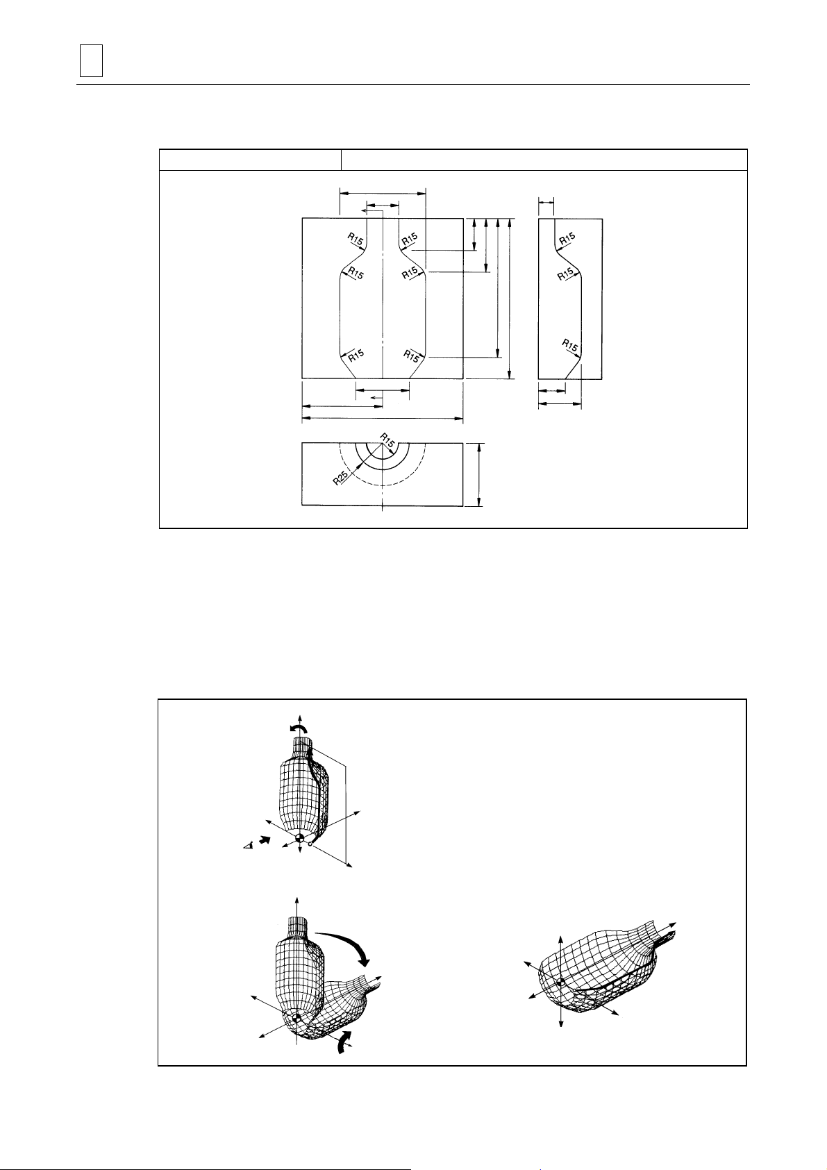
4 PROGRAMMING EXAMPLES
A
A
Y
4-12 ROTATE 1 + Coordinate Transfer
Programming example 12
80
30
’
50
75
150
ROTATE 1 + coordinate transfer
15
30
50
130
150
25
40
Section
A-A’
60
1) Definition of the plane
Define the figure line on the X-Z plane containing the workpiece zero point (WPC).
Unit: mm
D735P0554
2) Creation of the curved surface
Rotate the X-Z (+ side) plane containing the defined figure line (FL) around the Z-axis of the
workpiece coordinate system. In this case, set the rotational angle to –180°.
Rotate the generated curved surface –90° (clockwise) around the X-axis to transfer the
coordinates.
+Z
Curved surface is generated
by rotating 180°.
FL
+Y
Define FL on the
X-Z plane.
+X
+Y
Rotate 90° in the
clockwise direction.
+X
–X
+Z
FL
–Y
+X
–Z
Viewing po in t for
defining FL
–X
–Y
–X
–Y
–Z
+Z
–Z
+
D735P0555
4-30
Page 71

PROGRAMMING EXAMPLES 4
Program
[1]
UNo. UNIT GL-FL ROT.AXIS DIST/th. MAT-HIGH FIN CUT-PROCESS
1 ROTATE 1 0-1 Z 180. 0. 2. R1-F2
SNo. TOOL NOM-φ No. APRCH-X APRCH-Y TYPE DEPTH #T PITCH C-SP FR M M M
R1 BAL EMIL 20.A ? ? -1 5. 5 5. 200 0.25
F2 BAL EMIL 20.A ? ? -1 0. 2 5. 250 0.25
PLN LINE PLANE DISTANCE ROT.-X ROT.-Y ROT.-Z SHIFT-X SHIFT-Y SHIFT-Z
[2] FL X-Z !!!0. !!!
FIG PTN X Y R/th I J P CNR
1 LINE 25. 0.
2 LINE 40. 20. R15.
3 LINE 40. 100. R15.
4 LINE 15. 120. R15.
5 LINE 15. 150.
TRN PTN ROT.-X ROT.-Y ROT.-Z SHIFT-X SHIFT-Y SHIFT-Z
[3] SURF-MOVE -90. 0. 0. 0. 0. 0.
CSF PTN X-MIN X-MAX Y-MIN Y-MAX Z-MIN Z-MAX IN/OUT
AREA
[1] GL-FL
This indicates the number of the guide lines (GLs) and figure lines (FLs) used to define the
curved surfaces. With the ROTATE 1 unit, define one figure line (FL).
[2] PLN, FIG
PLN: The position of the X-Z plane used to define FL is to be defined.
FIG: The FL is to be defined.
[3] SURF-MOVE
The degree of rotational movement for the curved-surface figure is to be defined.
4-31
Page 72

4 PROGRAMMING EXAMPLES
4-13 Combination Program (Example 1)
Programming example 13 Combination program 1
150
120
Unit: mm
90
60
30
15
52.5
100
152.5
47.5
1) Definition of the plane
Define the figure lines (FLs) on the X-Z plane containing the workpiece zero point (WPC).
2) Creation of the curved surface
Define each of the 5 sections from A through E using the PARALL. 1 unit.
Set the distance between the workpiece zero point and machining starting point in
DISTANCE of the PLN for each unit.
+Z
D735P0556
–X
–X
+X
–Y
X
Viewing po in t for
defining FLs
+Z
–Z
FL on section
FL on section
Stock material
CSF plane
+X
+Y
E
D
FL on section
FL on section
FL on section
+Z
C
B
A
+X
D735P0557
4-32
Page 73

PROGRAMMING EXAMPLES 4
Program
(Section A)
UNo. UNIT GL-FL ROT.AXIS DIST/th. MAT-HIGH FIN CUT-PROCESS
1 PARALL.1 0-1 ! 30. 50. 1. R1-F2
SNo. TOOL NOM-φ No. APRCH-X APRCH-Y TYPE DEPTH #T PITCH C-SP FR M M M
R1 BAL EMIL 20.A 1 ? ? //-1 5. 5 5. 200 0.25
F2 BAL EMIL 20.A 2 ? ? //-1 0. 2 5. 250 0.25
PLN LINE PLANE DISTANCE ROT.-X ROT.-Y ROT.-Z SHIFT-X SHIFT-Y SHIFT-Z
FL X-Z 0. 0. 0. 0. 0. 0. 0.
FIG PTN X Y R/th I J P CNR
1 LINE -52.5 -12.5
2 CCW -40. 0. 12.5 ? ?
3 LINE -40. 15. R10.
4 LINE 0. 35. R10.
5 CW 35. 0. 35. ? ?
6 CCW 47.5 -12.5 12.5 ? ?
7 LINE 100. -12.5
TRN PTN ROT.-X ROT.-Y ROT.-Z SHIFT-X SHIFT-Y SHIFT-Z
SURF-MOVE 0. 0. 0. 0. 0. 0.
CSF PTN X-MIN X-MAX Y-MIN Y-MAX Z-MIN Z-MAX IN/OUT
AREA 0. 30. IN
(Section B)
UNo. UNIT GL-FL ROT.AXIS DIST/th. MAT-HIGH FIN CUT-PROCESS
2 PARALL.1 0-1 ! 30. 50. 1. R1-F2
SNo. TOOL NOM-φ No. APRCH-X APRCH-Y TYPE DEPTH #T PITCH C-SP FR M M M
R1 BAL EMIL 20.A 1 ? ? //-1 5. 5 5. 200 0.25
F2 BAL EMIL 20.A 2 ? ? //-1 0. 2 5. 250 0.25
PLN LINE PLANE DISTANCE ROT.-X ROT.-Y ROT.-Z SHIFT-X SHIFT-Y SHIFT-Z
FL X-Z 30. 0. 0. 0. 0. 0. 0.
FIG PTN X Y R/th I J P CNR
1 LINE -52.5 -12.5
2 LINE -32.5 -12.5
3 CCW -20. 0. 12.5 ? ?
4 CW 20. 0. 20. ? ?
5 CCW 32.5 -12.5 12.5 ? ?
6 LINE 100. -12.5
TRN PTN ROT.-X ROT.-Y ROT.-Z SHIFT-X SHIFT-Y SHIFT-Z
SURF-MOVE 0. 0. 0. 0. 0. 0.
CSF PTN X-MIN X-MAX Y-MIN Y-MAX Z-MIN Z-MAX IN/OUT
AREA 30. 60. IN
(Section C)
UNo. UNIT GL-FL ROT.AXIS DIST/th. MAT-HIGH FIN CUT-PROCESS
3 PARALL.1 0-1 ! 30. 50. 1. R1-F2
SNo. TOOL NOM-φ No. APRCH-X APRCH-Y TYPE DEPTH #T PITCH C-SP FR M M M
R1 BAL EMIL 20.A 1 ? ? //-1 5. 5 5. 200 0.25
F2 BAL EMIL 20.A 2 ? ? //-1 0. 2 5. 250 0.25
PLN LINE PLANE DISTANCE ROT.-X ROT.-Y ROT.-Z SHIFT-X SHIFT-Y SHIFT-Z
FL X-Z 60. 0. 0. 0. 0. 0. 0.
FIG PTN X Y R/th I J P CNR
1 LINE -52.5 -12.5
2 CCW -40. 0. 12.5 ? ?
3 LINE -40. 30. R10.
4 LINE 85. 30. R10.
5 LINE 85. 0.
6 CCW 100. -12.5 12.5 ? ?
TRN PTN ROT.-X ROT.-Y ROT.-Z SHIFT-X SHIFT-Y SHIFT-Z
SURF-MOVE 0. 0. 0. 0. 0. 0.
CSF PTN X-MIN X-MAX Y-MIN Y-MAX Z-MIN Z-MAX IN/OUT
AREA 60. 90. IN
4-33
Page 74

4 PROGRAMMING EXAMPLES
(Section D Copy the unit for section B and change the data in SURF-MOVE and AREA.)
UNo. UNIT GL-FL ROT.AXIS DIST/th. MAT-HIGH FIN CUT-PROCESS
4 PARALL.1 0-1 ! 30. 50. 1. R1-F2
SNo. TOOL NOM-φ No. APRCH-X APRCH-Y TYPE DEPTH #T PITCH C-SP FR M M M
R1 BAL EMIL 20.A 1 ? ? //-1 5. 5 5. 200 0.25
F2 BAL EMIL 20.A 2 ? ? //-1 0. 2 5. 250 0.25
PLN LINE PLANE DISTANCE ROT.-X ROT.-Y ROT.-Z SHIFT-X SHIFT-Y SHIFT-Z
FL X-Z 30. 0. 0. 0. 0. 0. 0.
FIG PTN X Y R/th I J P CNR
1 LINE -52.5 -12.5
2 LINE -32.5 -12.5
3 CCW -20. 0. 12.5 ? ?
4 CW 20. 0. 20. ? ?
5 CCW 32.5 -12.5 12.5 ? ?
6 LINE 100. -12.5
TRN PTN ROT.-X ROT.-Y ROT.-Z SHIFT-X SHIFT-Y SHIFT-Z
SURF-MOVE 0. 0. 180. 47.5 120. 0.
CSF PTN X-MIN X-MAX Y-MIN Y-MAX Z-MIN Z-MAX IN/OUT
AREA 90. 120. IN
(Section E Copy the unit for section A and change the data in SURF-MOVE and AREA.)
UNo. UNIT GL-FL ROT.AXIS DIST/th. MAT-HIGH FIN CUT-PROCESS
5 PARALL.1 0-1 ! 30. 50. 1. R1-F2
SNo. TOOL NOM-φ No. APRCH-X APRCH-Y TYPE DEPTH #T PITCH C-SP FR M M M
R1 BAL EMIL 20.A 1 ? ? //-1 5. 5 5. 200. 0.25
F2 BAL EMIL 20.A 2 ? ? //-1 0. 2 5. 250. 0.25
PLN LINE PLANE DISTANCE ROT.-X ROT.-Y ROT.-Z SHIFT-X SHIFT-Y SHIFT-Z
FL X-Z 0. 0. 0. 0. 0. 0. 0.
FIG PTN X Y R/th I J P CNR
1 LINE -52.5 -12.5
2 CCW -40. 0. 12.5 ? ?
3 LINE -40. 15. R10.
4 LINE 0. 35. R10.
5 CW 35. 0. 35. ? ?
6 CCW 47.5 -12.5 12.5 ? ?
7 LINE 100. -12.5
TRN PTN ROT.-X ROT.-Y ROT.-Z SHIFT-X SHIFT-Y SHIFT-Z
SURF-MOVE 0. 0. 180. 47.5 120. 0.
CSF PTN X-MIN X-MAX Y-MIN Y-MAX Z-MIN Z-MAX IN/OUT
AREA 120. 150. IN
Note: The tool priority numbers are input so that finish machining is undertaken after rough
machining.
4-34
Page 75

4-14 Combination Program (Example 2)
Programming example 14 Combination program 2
PROGRAMMING EXAMPLES 4
Unit: mm
A’
A
15
30
25
55
65
View of section
A-A ’
D735P0558
There are several ways to prepare the program for machining this shape and the two methods
described here involve dividing the shape into 3 sections and into 6 sections, respectively.
4-35
Page 76

4 PROGRAMMING EXAMPLES
∗
∗
A
1. 3-section method
As shown in the figures below, the shape is divided into 3 sections (A, B, and C), and the
programs for respective sections are then combined.
Machining
section
A
B
C
Machining unit
ROTATE 1
PARALL. 1
ROTATE 1
180° rotation
∗
FL
–X
Section C
(ROTATE 1)
180
°
rotation
+Y
50 mm parallel
movement
FL
–Y
Section B
(PARALL . 1)
+Z
–Z
180° rotation
FL
Section A
(ROTATE 1)
+X
180° rotation
FL
∗
Note: In this example, a small radius will be formed at the points indicated by ∗ due to the tool
path. Use the following 6-section method when a sharp corner is needed at these
points.
2. 6-section method
As shown in the figures below, the shape is divided into 6 sections (A, B, C, D, E, and F), and the
programs for respective sections are then combined.
D735P0559
Maching
section
B
C
D
E
F
Machining unit
ROTATE 1
PARALL. 1
ROTATE 1
ROTATE 1
PARALL. 1
ROTATE 1
E
+Y
D
C B A
F
–Y
E
+Z
C
F
C
F
B
–Z
A
E
D
+X–X
A
D
D735P0560
4-36
Page 77

PROGRAMMING EXAMPLES 4
The program for the 6-section method is presented here.
Machining is performed using 3-D machining units as well as the regular machining units.
D735P0561
Program
(Area outside the generated shape)
UNo. UNIT DEPTH SRV-Z SRV-R BTM WAL FIN-Z FIN-R
1 STEP 15. 30. ! 5. 5. 0.14 0.14
SNo. TOOL NOM-φ No. APRCH-X APRCH-Y TYPE ZFD DEPTH-Z DEPTH-R C-SP FR M M M
R1 END MILL 25.B ? ? CW G01 14.79 17.5 200 0.3
F2 END MILL 25.B ? ? CW G01 ! 17.5 250 0.3
FIG PTN P1X/CX P1Y/CY P3X/R P3Y CN1 CN2 CN3 CN4
1 SQR -75. -75. 75. 75.
2 SQR -72. -50. 72. 50. R 50. R 50. R 50. R 50.
(Section A)
UNo. UNIT GL-FL ROT.AXIS DIST/th. MAT-HIGH FIN CUT-PROCESS
2 ROTATE 1 0-1 Z 180. 20. 0.1 R1-F2
SNo. TOOL NOM-φ No. APRCH-X APRCH-Y TYPE DEPTH #T PITCH C-SP FR M M M
R1 BAL EMIL 20.A ? ? //-1 5. 5 5. 200 0.25
F2 BAL EMIL 20.A ? ? //-1 0. 2 5. 250 0.25
PLN LINE PLANE DISTANCE ROT.-X ROT.-Y ROT.-Z SHIFT-X SHIFT-Y SHIFT-Z
FL X-Z !!!90. !!!
FIG PTN X Y R/th I J P CNR
1 LINE 0. 15.
2 CCW -15. 0. 15. ? ? LEFT R 10.
3 LINE -30. 0.
TRN PTN ROT.-X ROT.-Y ROT.-Z SHIFT-X SHIFT-Y SHIFT-Z
SURF-MOVE 0. 0. 0. 0. 25. 0.
CSF PTN X-MIN X-MAX Y-MIN Y-MAX Z-MIN Z-MAX IN/OUT
AREA 0. IN
(Section B)
UNo. UNIT GL-FL ROT.AXIS DIST/th. MAT-HIGH FIN CUT-PROCESS
3 PARALL.1 0-1 ! 50. 20. 0.1 R1-F2
SNo. TOOL NOM-φ No. APRCH-X APRCH-Y TYPE DEPTH #T PITCH C-SP FR M M M
R1 BAL EMIL 20.A ? ? //-1 5. 5 5. 200 0.25
F2 BAL EMIL 20.A ? ? //-1 0. 2 5. 250 0.25
PLN LINE PLANE DISTANCE ROT.-X ROT.-Y ROT.-Z SHIFT-X SHIFT-Y SHIFT-Z
FL Y-Z -25. 0. 0. 0. 0. 0. 0.
FIG PTN X Y R/th I J P CNR
1 LINE 30. 0.
2 LINE 15. 0. R 10.
3 CCW -15. 0. 15. ? ? LEFT R 10.
4 LINE -30. 0.
TRN PTN ROT.-X ROT.-Y ROT.-Z SHIFT-X SHIFT-Y SHIFT-Z
1 SURF-MOVE 0. 0. 0. 25. 0. 0.
CSF PTN X-MIN X-MAX Y-MIN Y-MAX Z-MIN Z-MAX IN/OUT
AREA 0. IN
4-37
Page 78

4 PROGRAMMING EXAMPLES
(Section C Copy the unit for section A and change the data in SURF-MOVE.)
UNo. UNIT GL-FL ROT.AXIS DIST/th. MAT-HIGH FIN CUT-PROCESS
3 ROTATE 1 0-1 Z 180. 20. 0.1 R1-F2
SNo. TOOL NOM-φ No. APRCH-X APRCH-Y TYPE DEPTH #T PITCH C-SP FR M M M
R1 BAL EMIL 20.A ? ? //-1 5. 5 5. 200 0.25
F2 BAL EMIL 20.A ? ? //-1 0. 2 5. 250 0.25
PLN LINE PLANE DISTANCE ROT.-X ROT.-Y ROT.-Z SHIFT-X SHIFT-Y SHIFT-Z
FL X-Z !!!90. !!!
FIG PTN X Y R/th I J P CNR
1 LINE 0. 15.
2 CCW -15. 0. 15. ? ?
3 LINE -30. 0.
TRN PTN ROT.-X ROT.-Y ROT.-Z SHIFT-X SHIFT-Y SHIFT-Z
SURF-MOVE 0. 0. 180. -25. 0. 0.
CSF PTN X-MIN X-MAX Y-MIN Y-MAX Z-MIN Z-MAX IN/OUT
AREA 0. IN
(Section D)
UNo. UNIT GL-FL ROT.AXIS DIST/th. MAT-HIGH FIN CUT-PROCESS
5 ROTATE 1 0-1 Z 180. 20. 0.1 R1-F2
SNo. TOOL NOM-φ No. APRCH-X APRCH-Y TYPE DEPTH #T PITCH C-SP FR M M M
R1 BAL EMIL 20.A ? ? //-1 5. 5 5. 200 0.25
F2 BAL EMIL 20.A ? ? //-1 0. 2 5. 250 0.25
PLN LINE PLANE DISTANCE ROT.-X ROT.-Y ROT.-Z SHIFT-X SHIFT-Y SHIFT-Z
FL X-Z !!!90 !!!
FIG PTN X Y R/th I J P CNR
1 LINE -30. 0.
2 LINE -40. -15.
TRN PTN ROT.-X ROT.-Y ROT.-Z SHIFT-X SHIFT-Y SHIFT-Z
SURF-MOVE 0. 0. 0. 25. 0. 0.
CSF PTN X-MIN X-MAX Y-MIN Y-MAX Z-MIN Z-MAX IN/OUT
AREA -15. IN
(Section E)
UNo. UNIT GL-FL ROT.AXIS DIST/th. MAT-HIGH FIN CUT-PROCESS
6 PARALL.1 0-1 ! 50. 20. 0.1 R1-F2
SNo. TOOL NOM-φ No. APRCH-X APRCH-Y TYPE DEPTH #T PITCH C-SP FR M M M
R1 BAL EMIL 20.A ? ? //-1 5. 5 5. 200 0.25
F2 BAL EMIL 20.A ? ? //-1 0. 2 5. 250 0.25
PLN LINE PLANE DISTANCE ROT.-X ROT.-Y ROT.-Z SHIFT-X SHIFT-Y SHIFT-Z
FL X-Z -25. 0. 0. 0. 0. 0. 0.
FIG PTN X Y R/th I J P CNR
1 LINE 40. -15.
2 LINE 30 0.
3 LINE -30 0.
4 LINE -40. -15.
CSF PTN X-MIN X-MAX Y-MIN Y-MAX Z-MIN Z-MAX IN/OUT
AREA -30. 30. OUT
(Section F Copy the unit for section D and change the data in SURF-MOVE.)
UNo. UNIT GL-FL ROT.AXIS DIST/th. MAT-HIGH FIN CUT-PROCESS
7 ROTATE 1 0-1 Z 180. 20. 0.1 R1-F2
SNo. TOOL NOM-φ No. APRCH-X APRCH-Y TYPE DEPTH #T PITCH C-SP FR M M M
R1 BAL EMIL 20.A ? ? //-1 5. 5 5. 200 0.25
F2 BAL EMIL 20.A ? ? //-1 0. 2 5. 250 0.25
PLN LINE PLANE DISTANCE ROT.-X ROT.-Y ROT.-Z SHIFT-X SHIFT-Y SHIFT-Z
FL X-Z !!!90. !!!
FIG PTN X Y R/th I J P CNR
1 LINE -30. 0.
2 LINE -40 -15.
TRN PTN ROT.-X ROT.-Y ROT.-Z SHIFT-X SHIFT-Y SHIFT-Z
SURF-MOVE 0. 0. 180. -25. 0. 0.
CSF PTN X-MIN X-MAX Y-MIN Y-MAX Z-MIN Z-MAX IN/OUT
AREA -15. IN
LEFT
R 10.
4-38
E
Page 79

5 RELATIVE PARAMETERS
The parameters relative to the 3D machining are shown below. Refer to the separate Parameter
List/Alarm List/M-Code List for further detail.
Address Description
E55 Axial cutting-feed overriding
E56 Inversion check of curved-surface figure
E57 Severity check of cutting pitch
E58 Tool-diameter compensation
E59 Allowance for axial-cutting start position
E60 Normal cutting allowance
E61 Search length for parallel cutting
E62 Search length for right-angle cutting
E63 Ruled-surface division along FL
E64 Ruled-surface division along GL
E65 Radial cutting allowance for machining area appointment
E66 Axial cutting allowance for machining area appointment
E67 Machining error tolerance when #T of the tool sequence is set to 1
E68 Machining error tolerance when #T of the tool sequence is set to 2
E69 Machining error tolerance when #T of the tool sequence is set to 3
E70 Machining error tolerance when #T of the tool sequence is set to 4
E71 Machining error tolerance when #T of the tool sequence is set to 5
E72 Machining error tolerance when #T of the tool sequence is set to 6
E73 Machining error tolerance when #T of the tool sequence is set to 7
E74 Machining error tolerance when #T of the tool sequence is set to 8
E75 Machining error tolerance when #T of the tool sequence is set to 9
E76 Entire-width override
E77 Radial cutting allowance for high-speed rough machining (workpiece size appointment)
E78 Multiplying factor set for tolerance (%)
E83 Radial machining area for high-speed rough machining (offset appointment)
E84 Axial machining area for high-speed rough machining (offset appointment)
E85 Radial machining area (–X direction) for high-speed rough machining (workpiece size appointment)
E86 Radial machining area (+X direction) for high-speed rough machining (workpiece size appointment)
E87 Radial machining area (–Y direction) for high-speed rough machining (workpiece size appointment)
E88 Radial machining area (+Y direction) for high-speed rough machining (workpiece size appointment)
E89 Axial machining area for high-speed rough machining ( workpiece size appointment)
RELATIVE PARAMETERS 5
5-1
Page 80

5 RELATIVE PARAMETERS
- NOTE -
5-2
E
 Loading...