

Page 1

PROGRAMMING MANUAL
Return to Main Menu
for
MAZATROL MATRIX
(For INTEGREX IV)
MAZATROL Program
MANUAL No. : H740PA0031E
Serial No. :
Before using this machine and equipment, fully understand the contents of this
manual to ensure proper operation. Should any questions arise, please ask the
nearest Technical Center or Technology Center.
IMPORTANT NOTICE
1. Be sure to observe the safety precautions described in this manual and the contents of the
safety plates on the machine and equipment. Failure may cause serious personal injury or
material damage. Please replace any missing safety plates as soon as possible.
2. No modifications are to be performed that will affect operation safety. If such modifications are
required, please contact the nearest Technical Center or Technology Center.
3. For the purpose of explaining the operation of the machine and equipment, some illustrations
may not include safety features such as covers, doors, etc. Before operation, make sure all
such items are in place.
4. This manual was considered complete and accurate at the time of publication, however, due to
our desire to constantly improve the quality and specification of all our products, it is subject to
change or modification. If you have any questions, please contact the nearest Technical Center
or Technology Center.
5. Always keep this manual near the machinery for immediate use.
6. If a new manual is required, please order from the nearest Technical Center or Technology
Center with the manual No. or the machine name, serial No. and manual name.
Issued by Manual Publication Section, Yamazaki Mazak Corporation, Japan
10. 2006
Page 2

Page 3
SAFETY PRECAUTIONS
Preface
Safety precautions relating to the CNC unit (in the remainder of this manual, referred to simply as
the NC unit) that is provided in this machine are explained below. Not only the persons who
create programs, but also those who operate the machine must thoroughly understand the
contents of this manual to ensure safe operation of the machine.
Read all these safety precautions, even if your NC model does not have the corresponding
functions or optional units and a part of the precautions do not apply.
Rule
1. This section contains the precautions to be observed as to the working methods and states
usually expected. Of course, however, unexpected operations and/or unexpected working
states may take place at the user site.
During daily operation of the machine, therefore, the user must pay extra careful attention to
its own working safety as well as to observe the precautions described below.
2. Although this manual contains as great an amount of information as it can, since it is not
rare for the user to perform the operations that overstep the manufacturer-assumed ones,
not all of “what the user cannot perform” or “what the user must not perform” can be fully
covered in this manual with all such operations taken into consideration beforehand.
It is to be understood, therefore, that functions not clearly written as “executable” are
“inexecutable” functions.
SAFETY PRECAUTIONS
3. The meanings of our safety precautions to DANGER, WARNING, and CAUTION are as
follows:
: Failure to follow these instructions could result in loss of life.
DANGER
: Failure to observe these instructions could result in serious harm to a human
life or body.
WARNING
: Failure to observe these instructions could result in minor injuries or serious
machine damage.
CAUTION
HGENPA0043E
S-1
Page 4
Basics
SAFETY PRECAUTIONS
! After turning power on, keep hands away from the keys, buttons, or switches of the
operating panel until an initial display has been made.
WARNING
! Before proceeding to the next operations, fully check that correct data has been entered
and/or set. If the operator performs operations without being aware of data errors,
unexpected operation of the machine will result.
! Before machining workpieces, perform operational tests and make sure that the machine
operates correctly. No workpieces must be machined without confirmation of normal
operation. Closely check the accuracy of programs by executing override, single-block, and
other functions or by operating the machine at no load. Also, fully utilize tool path check,
Virtual Machining, and other functions, if provided.
! Make sure that the appropriate feed rate and rotational speed are designated for the
particular machining requirements. Always understand that since the maximum usable fee d
rate and rotational speed are determined by the specifications of the tool to be used, those
of the workpiece to be machined, and various other factors, actual capabilities differ from
the machine specifications listed in this manual. If an inappropriate feed rate or rotational
speed is designated, the workpiece or the tool may abruptly move out from the machine.
! Before executing correction functions, fully check that the direction and amount of
correction are correct. Unexpected operation of the machine will result if a correction
function is executed without its thorough understanding.
! Parameters are set to the optimum standard machining conditions prior to shipping of the
machine from the factory. In principle, these settings should not be modified. If it becomes
absolutely necessary to modify the settings, perform modifications only after thoroughly
understanding the functions of the corresponding parameters. Modifications usually affect
any program. Unexpected operation of the machine will result if the settings are modified
without a thorough understanding.
Remarks on the cutting conditions recommended by the NC
! Before using the following cutting conditions:
- Cutting conditions that are the result of the MAZATROL Automatic Cutting Conditions
WARNING
Determination Function
- Cutting conditions suggested by the Machining Navigation Function
- Cutting conditions for tools that are suggested to be used by the Machining Navigation
Function
Confirm that every necessary precaution in regards to safe machine setup has been taken –
especially for workpiece fixturing/clamping and tool setup.
! Confirm that the machine door is securely closed before starting machining.
Failure to confirm safe machine setup may result in serious injury or death.
S-2
Page 5

Programming
WARNING
SAFETY PRECAUTIONS
! Fully check that the settings of the coordinate systems are correct. Even if the designated
program data is correct, errors in the system settings may cause the machine to operate in
unexpected places and the workpiece to abruptly move out from the machine in the event
of contact with the tool.
! During surface velocity hold control, as the current workpiece coordinates of the surface
velocity hold control axes approach zeroes, the spindle speed increases significantly. For
the lathe, the workpiece may even come off if the chucking force decreases. Safety speed
limits must therefore be observed when designating spindle speeds.
! Even after inch/metric system selection, the units of the programs, tool information, or
parameters that have been registered until that time are not converted. Fully check these
data units before operating the machine. If the machine is operated without checks being
performed, even existing correct programs may cause the machine to operate differently
from the way it did before.
! If a program is executed that includes the absolute data commands and relative data
commands taken in the reverse of their original meaning, totally unexpected operation of
the machine will result. Recheck the command scheme before executing programs.
! If an incorrect plane selection command is issued for a machine action such as arc
interpolation or fixed-cycle machining, the tool may collide with the workpiece or part of the
machine since the motions of the control axes assumed and those of actual ones will be
interchanged. (This precaution applies only to NC units provided with EIA functions.)
! The mirror image, if made valid, changes subsequent machine actions significantly. Use
the mirror image function only after thoroughly understanding the above. (This precaution
applies only to NC units provided with EIA functions.)
! If machine coordinate system commands or reference position returning commands are
issued with a correction function remaining made valid, correction may become invalid
temporarily. If this is not thoroughly understood, the machine may appear as if it would
operate against the expectations of the operator. Execute the above commands only after
making the corresponding correction function invalid. (This precaution applies only to NC
units provided with EIA functions.)
! The barrier function performs interference checks based on designated tool data. Enter the
tool information that matches the tools to be actually used. Otherwise, the barrier function
will not work correctly.
! The system of G-code and M-code commands differs, especially for turning, between the
machines of INTEGREX e-Series and the other turning machines.
Issuance of the wrong G-code or M-code command results in totally non-intended machine
operation. Thoroughly understand the system of G-code and M-code commands before
using this system.
Sample program Machines of INTEGREX e-Series Turning machines
S1000M3
S1000M203
The milling spindle rotates at 1000 min–1. The turning spindle rotates at 1000 min–1.
The turning spindle rotates at 1000 min–1. The milling spindle rotates at 1000 min–1.
S-3
Page 6
SAFETY PRECAUTIONS
! For the machines of INTEGREX e-Series, programmed coordinates can be rotated using
an index unit of the MAZATROL program and a G68 command (coordinate rotate command) of the EIA program. However, for example, when the B-axis is rotated through 180
degrees around the Y-axis to implement machining with the turning spindle No. 2, the plus
side of the X-axis in the programmed coordinate system faces downward and if the
program is created ignoring this fact, the resulting movement of the tool to unexpected
positions may incite collisions.
To create the program with the plus side of the X-axis oriented in an upward direction, use
the mirror function of the WPC shift unit or the mirror imaging function of G-code command
(G50.1, G51.1).
! After modifying the tool data specified in the program, be sure to perform the tool path
check function, the Virtual Machining function, and other functions, and confirm that the
program operates properly. The modification of tool data may cause even a field-proven
machining program to change in operational status.
If the user operates the machine without being aware of any changes in program status,
interference with the workpiece could arise from unexpected operation.
For example, if the cutting edge of the tool during the start of automatic operation is present
inside the clearance-including blank (unmachined workpiece) specified in the common unit
of the MAZATROL program, care is required since the tool will directly move from that
position to the approach point because of no obstructions being judged to be present on
this path.
For this reason, before starting automatic operation, make sure that the cutting edge of the
tool during the start of automatic operation is present outside the clearance-including
workpiece specified in the common unit of the MAZATROL program.
CAUTION
! If axis-by-axis independent positioning is selected and simultaneously rapid feed selected
for each axis, movements to the ending point will not usually become linear. Before using
these functions, therefore, make sure that no obstructions are present on the path.
! Before starting the machining operation, be sure to confirm all contents of the program
obtained by conversion. Imperfections in the program could lead to machine damage and
operator injury.
S-4
Page 7
Operations
WARNING
SAFETY PRECAUTIONS
! Single-block, feed hold, and override functions can be made invalid using system variables
#3003 and #3004. Execution of this means the important modification that makes the
corresponding operations invalid. Before using these variables, therefore, give thorough
notification to related persons. Also, the operator must check the settings of the system
variables before starting the above operations.
! If manual intervention during automatic operation, machine locking, the mirror image
function, or other functions are executed, the workpiece coordinate systems will usually be
shifted. When making machine restart after manual intervention, machine locking, the
mirror image function, or other functions, consider the resulting amounts of shift and take
the appropriate measures. If operation is restarted without any appropriate measures being
taken, collision with the tool or workpiece may occur.
! Use the dry run function to check the machine for normal operation at no load. Since the
feed rate at this time becomes a dry run rate different from the program-designated feed
rate, the axes may move at a feed rate higher than the programmed value.
! After operation has been stopped temporarily and insertion, deletion, updating, or other
commands executed for the active program, unexpected operation of the machine may
result if that program is restarted. No such commands should, in principle, be issued for the
active program.
CAUTION
! During manual operation, fully check the directions and speeds of axial movement.
! For a machine that requires manual homing, perform manual homing operations after
turning power on. Since the software-controlled stroke limits will remain ineffective until
manual homing is completed, the machine will not stop even if it oversteps the limit area.
As a result, serious machine damage will result.
! Do not designate an incorrect pulse multiplier when performing manual pulse handle feed
operations. If the multiplier is set to 1000 times and the handle operated inadvertently, axial
movement will become faster than that expected.
S-5
Page 8

BEFORE USING THE NC UNIT
BEFORE USING THE NC UNIT
Limited Warranty
The warranty of the manufacturer does not cover any trouble arising if the NC unit is used for its
non-intended purpose. Take notice of this when operating the unit.
Examples of the trouble arising if the NC unit is used for its non-intended purpose are listed
below.
1. Trouble associated with and caused by the use of any commercially available software
products (including user-created ones)
2. Trouble associated with and caused by the use of any Windows operating systems
3. Trouble associated with and caused by the use of any commercially available computer
equipment
Operating Environment
1. Ambient temperature
During machine operation: 0° to 50°C (32° to 122°F)
2. Relative humidity
During machine operation: 10 to 75% (without bedewing)
Note: As humidity increases, insulation deteriorates causing electrical component parts to
deteriorate quickly.
Keeping the Backup Data
Note: Do not attempt to delete or modify the data stored in the following folder.
Recovery Data Storage Folder: D:\MazakBackUp
Although this folder is not used when the NC unit is running normally, it contains important data
that enables the prompt recovery of the machine if it fails.
If this data has been deleted or modified, the NC unit may require a long recovery time. Be sure
not to modify or delete this data.
S-6
E
Page 9

CONTENTS
Page
1 MAZATROL PROGRAM CONFIGURATION........................................ 1-1
1-1 Program Configuration .......................................................................................1-1
2 PROGRAM COORDINATE SYSTEM .................................................. 2-1
3 PROGRAM CREATION........................................................................ 3-1
3-1 Procedure for Program Creation ........................................................................3-1
3-2 Common Unit .....................................................................................................3-6
3-2-1 Setting unit data (common data)............................................................................. 3-6
3-3 Materials Shape Unit (MATERIAL).....................................................................3-8
3-3-1 Setting unit data...................................................................................................... 3-8
3-3-2 Setting sequence data............................................................................................ 3-8
3-4 Types of the Milling Unit...................................................................................3-12
3-4-1 Planes to be machined and machining methods.................................................. 3-12
3-5 Point Machining Units.......................................................................................3-15
3-5-1 Types of point machining units.............................................................................3-15
3-5-2 Procedure for selecting point machining unit........................................................ 3-16
3-5-3 Unit data and automatic tool development of the point machining unit ................ 3-17
3-5-4 Automatic tool development for carbide drills....................................................... 3-35
3-5-5 New tapping auto-setting scheme ........................................................................ 3-36
3-5-6 Tool sequence data of the point machining unit...................................................3-41
3-5-7 Tool path of the point machining unit.................................................................... 3-47
3-5-8 Shape sequence data of the point machining unit................................................ 3-96
3-6 Line Machining Units......................................................................................3-116
C-1
Page 10

3-6-1 Types of line machining units ............................................................................. 3-116
3-6-2 Procedure for selecting line machining unit........................................................ 3-117
3-6-3 Unit data, automatic tool development and tool path of the line machining
unit...................................................................................................................... 3-118
3-6-4 Tool sequence data of the line machining unit ................................................... 3-157
3-6-5 Shape sequence data of the line machining unit................................................ 3-160
3-6-6 Precautions in line machining............................................................................. 3-161
3-6-7 Automatic corner override................................................................................... 3-165
3-7 Face Machining Units.....................................................................................3-167
3-7-1 Types of face machining units............................................................................3-167
3-7-2 Procedure for selecting face machining unit....................................................... 3-168
3-7-3 Unit data, automatic tool development and tool path of the face machining
unit...................................................................................................................... 3-169
3-7-4 Tool sequence data of the face machining unit..................................................3-214
3-7-5 Precautions in face machining............................................................................ 3-220
3-7-6 Override in case of the overall width cutting....................................................... 3-230
3-7-7 Shape sequence data of the line/face machining unit........................................3-232
3-8 Turning Units..................................................................................................3-257
3-8-1 Types of turning units ......................................................................................... 3-257
3-8-2 Procedure for selecting turning unit.................................................................... 3-257
3-9 Bar-Materials Machining Unit (BAR)...............................................................3-259
3-9-1 Setting unit data.................................................................................................. 3-259
3-9-2 Setting tool sequence data................................................................................. 3-263
3-9-3 Setting shape sequence data............................................................................. 3-269
3-10 Copy-Machining Unit (CPY) ...........................................................................3-274
C-2
Page 11

3-10-1 Setting unit data.................................................................................................. 3-274
3-10-2 Setting tool sequence data................................................................................. 3-276
3-10-3 Setting shape sequence data............................................................................. 3-278
3-11 Corner-Machining Unit (CORNER).................................................................3-279
3-11-1 Setting unit data.................................................................................................. 3-279
3-11-2 Setting tool sequence data................................................................................. 3-280
3-11-3 Setting shape sequence data............................................................................. 3-282
3-12 Facing Unit (FACING) ....................................................................................3-283
3-12-1 Setting unit data.................................................................................................. 3-283
3-12-2 Setting tool sequence data................................................................................. 3-284
3-12-3 Setting shape sequence data............................................................................. 3-286
3-13 Threading Unit (THREAD)..............................................................................3-288
3-13-1 Setting unit data.................................................................................................. 3-288
3-13-2 Setting tool sequence data................................................................................. 3-291
3-13-3 Setting sequence data........................................................................................ 3-294
3-14 Grooving Unit (T. GROOVE)..........................................................................3-297
3-14-1 Setting unit data.................................................................................................. 3-297
3-14-2 Setting tool sequence data................................................................................. 3-300
3-14-3 Setting shape sequence data............................................................................. 3-304
3-15 Turning Drilling Unit (T. DRILL) ......................................................................3-308
3-15-1 Setting unit data.................................................................................................. 3-308
3-15-2 Setting tool sequence data................................................................................. 3-309
3-15-3 Setting shape sequence data............................................................................. 3-315
3-16 Turning Tapping Unit (T. TAP) .......................................................................3-316
C-3
Page 12

3-16-1 Setting unit data.................................................................................................. 3-316
3-16-2 Setting tool sequence data................................................................................. 3-319
3-16-3 Setting shape sequence data............................................................................. 3-321
3-17 Mill-Turning Unit (MILLTURN)........................................................................3-322
3-17-1 Setting unit data.................................................................................................. 3-322
3-17-2 Setting tool sequence data................................................................................. 3-323
3-17-3 Setting shape sequence data............................................................................. 3-325
3-18 Other Units.....................................................................................................3-326
3-19 Manual Program Machining Unit (MANL PRG)..............................................3-327
3-19-1 Setting unit data.................................................................................................. 3-327
3-19-2 Setting sequence data........................................................................................ 3-329
3-20 M-Code Unit (M-CODE) .................................................................................3-331
3-20-1 Setting unit data (M-code) .................................................................................. 3-331
3-21 Head Selection Unit (HEAD) ..........................................................................3-333
3-21-1 Setting unit data.................................................................................................. 3-333
3-22 Workpiece Transfer Unit (TRANSFER)..........................................................3-334
3-22-1 Setting unit data.................................................................................................. 3-334
3-23 Subprogram Unit (SUB PRO).........................................................................3-338
3-23-1 Setting unit data.................................................................................................. 3-338
3-23-2 Setting sequence data........................................................................................ 3-339
3-24 Add-In MAZATROL Unit.................................................................................3-341
3-24-1 Setting unit data.................................................................................................. 3-341
3-24-2 Setting sequence data........................................................................................ 3-341
3-24-3 Help function on Add-in MAZATROL.................................................................. 3-342
C-4
Page 13

3-25 End Unit (END)...............................................................................................3-346
3-25-1 Setting unit data.................................................................................................. 3-346
3-25-2 Setting sequence data........................................................................................ 3-350
3-26 Simultaneous Machining Unit (SIMULTAN)....................................................3-351
3-26-1 Procedure for calling up the SIMULTAN unit...................................................... 3-351
3-26-2 Setting unit data.................................................................................................. 3-351
3-27 Two-Workpiece Machining Unit (2 WORKPC) ...............................................3-352
3-27-1 Procedure for calling up the 2 WORKPC unit..................................................... 3-352
3-27-2 Setting unit data.................................................................................................. 3-352
3-28 Coordinate Measuring Unit (MMS).................................................................3-353
3-28-1 Procedure for calling up the MMS unit................................................................ 3-353
3-28-2 Setting unit data.................................................................................................. 3-353
3-28-3 Setting sequence data........................................................................................ 3-353
3-28-4 Type of measurement......................................................................................... 3-355
3-29 Workpiece Measuring Unit (WORK MES)......................................................3-358
3-29-1 Procedure for selecting workpiece measuring unit............................................. 3-358
3-29-2 Setting the unit data............................................................................................ 3-358
3-29-3 Setting the sequence data.................................................................................. 3-359
3-29-4 Selection of a measurement type.......................................................................3-360
3-29-5 Offset value and the direction of offset............................................................... 3-369
3-29-6 Offset judgment .................................................................................................. 3-373
3-30 Tool Measuring Unit (TOOL MES)..................................................................3-374
3-30-1 Procedure for selecting tool measuring unit ....................................................... 3-374
3-30-2 Setting the unit data............................................................................................ 3-374
C-5
Page 14

3-30-3 Setting the sequence data.................................................................................. 3-375
3-30-4 Measuring patterns............................................................................................. 3-376
4 PRIORITY FUNCTION FOR THE SAME TOOL................................... 4-1
4-1 Priority Machining Order.....................................................................................4-1
4-2 Priority Machining Zone......................................................................................4-4
4-3 Editing Function and Input Method of Priority Numbers .....................................4-6
4-3-1 Input of priority numbers......................................................................................... 4-6
4-3-2 Assignment of priority numbers .............................................................................. 4-7
4-3-3 Change of priority numbers .................................................................................... 4-8
4-3-4 Deletion of all the priority numbers.........................................................................4-9
4-3-5 How to use the SUB PROG PROC END function .................................................. 4-9
4-4 Relation between the Subprogram Unit and the Priority Machining
Function............................................................................................................4-11
4-5 Relation between the M-Code Unit and the Priority Machining Function..........4-12
5 LOWER-TURRET CONTROL FUNCTIONS ........................................ 5-1
5-1 Machining with the Lower Turret ........................................................................5-1
5-1-1 Independent machining with the lower turret.......................................................... 5-1
5-1-2 Simultaneous machining with the upper and lower turrets ..................................... 5-2
5-1-3 Balanced cutting with the upper and lower turrets.................................................. 5-6
5-1-4 Simultaneous machining of processes 1 and 2, using the upper and lower
turrets (optional)...................................................................................................... 5-7
5-2 Retraction of the Lower Turret..........................................................................5-10
5-3 Other Setup Items............................................................................................5-12
5-3-1 LTUR DIA in common unit.................................................................................... 5-12
C-6
Page 15

6 TPC DATA SETTING ........................................................................... 6-1
6-1 Operating Procedure for Setting TPC (Tool-Path Control) Data.........................6-1
6-2 Description of Each TPC Data Item of Turning Unit and Measurement
Unit.....................................................................................................................6-4
7 PROGRAM EDITING............................................................................ 7-1
7-1 Operating Procedures for Editing Programs.......................................................7-1
7-2 Search................................................................................................................7-2
7-3 Insertion..............................................................................................................7-6
7-4 Deletion............................................................................................................7-10
7-5 Copy.................................................................................................................7-14
8 PROGRAM CREATING/EDITING FUNCTIONS.................................. 8-1
8-1 Help Function.....................................................................................................8-1
8-2 Automatic Crossing-Point Calculation Function..................................................8-2
8-2-1 Automatic crossing-point calculation in the line and face machining units............. 8-2
8-2-2 Automatic crossing-point calculation function in the turning unit............................8-6
8-3 Automatic Cutting-Conditions Setting Function................................................8-15
8-4 Desk Calculator Functions................................................................................8-18
8-5 Tool Data Window............................................................................................8-19
8-6 Tool File Window..............................................................................................8-20
9 SAMPLE PROGRAMS......................................................................... 9-1
10 THREE-DIGIT G-FORMAT................................................................. 10-1
10-1 Outline.............................................................................................................. 10-1
C-7
Page 16

10-2 Detailed Description .........................................................................................10-1
10-3 Three-Digit G-Format of MAZATROL Program................................................10-2
10-4 Various Data Description Using G10..............................................................10-20
C-8
E
Page 17
1 MAZATROL PROGRAM CONFIGURATION
x
1-1 Program Configuration
MAZATROL programs are each made up of a set of data referred to as unit. The following types of
units are prepared for this NC equipment:
Common unit
Materials shape unit
Machining unit Milling unit Point mach ining unit Drilling
MAZATROL PROGRAM CONFIGURATION 1
Counterbore machining
Inversed faced hole machining
Reaming
Tapping
Boring Through hole
Non-through hole
Stepped through hole
Stepped non-through hole
Back boring
Circular milling
Counterbore-tapping
Line machining unit Central linear machining
Face machining unit Face milling
Turning unit Bar-materials machining
Manual program machining unit Copy-machining
End unit Corner-machining
M-code unit Facing
Subprogram unit Threading
Coordinate measuring unit Grooving
Workpiece measuring unit Drilling (turning)
Tool measuring unit Tapping (turning)
Head selection unit Mill-turning
Workpiece transfer unit
Process end unit
Simultaneous machining unit
Two-workpiece machining unit
Add-in MAZATROL unit
Right-hand linear machining
Left-hand linear machining
Outside linear machining
Inside linear machining
Right-hand chamfering
Left-hand chamfering
Outside chamfering
Inside chamfering
End milling-top
End milling-step
Pocket milling
Pocket milling-mountain
Pocket milling-valley
End milling slot
E
1-1
Page 18

1 MAZATROL PROGRAM CONFI GURATION
Data to be set in the units listed above is classified into the following four major types:
1. Unit data
The data consists of data on the type of machining and the sections to be machined, etc.
2. Tool sequence data
The tool sequence data consists of tool names and other data relating to the operation of
the tools. This type of data exists for the milling (point, linear, and face machining) and
turning units. For other units, data relating to tools exists with the unit data.
3. Shape sequence data
The data consists mainly of data used to define machining patterns.
4. TPC data (Tool path control data)
TPC data is the auxiliary data to be set on the TPC display. The data consists of tool
path/tool change position adjustment data, M-codes, tool offset numbers, etc. Tool paths
are automatically generated according to the data set on the PROGRAM display and
various parameters. TPC data is intended to eliminate unnecessary paths by changing
thus-generated tool paths on an unit-by-unit basis. Machining itself, therefore, will be
executed even if TPC data is not set.
Example: PROGRAM display
UNo. MAT. OD-MAX ID-MIN LENGTH WORK FACE ATC MODE RPM LTUR DIA
A
0 FC 70. 0. 97. 2 0 3000
UNo. UNIT MODE POS-B POS-C DIA DEPTH CHMF
A
1 DRILLING ZC ! ! 10. 20. 0.
SNo.TOOL NOM-φ No. # HOLE-φ HOLE-DEP PRE-DIA PRE-DEP RGH DEPTH C-SP FR M M M
B
1 CTR-DR 12. A 10. !! ! 90. SPOT 25 0.1
2 DRILL 10. 10. 20. 0. 100 DRIL T 5. 63 0.1
FIG PTN SPT-R/x SPT-C/y SPT-Z SPT-Y NUM. ANGLE Q R
C
1 PT 0. 0. 0. 0. ! ! ! 0
UNo. UNIT MODE POS-B POS-C SRV-A SLOT-WID BTM WAL FIN-A FIN-R PAT.
A
2 SLOT ZY ! 90. 10. 20. 4 4 0. 0. 0
SNo. TOOL NOM-φ No. # APRCH-1 APRCH-2 TYPE AFD DEP-A DEP-R C-SP FR M M M
B
F1 END MILL 20. A ? ? CW G01 ! ! 120 0.13
FIG PTN SPT-R Z Y R/th I J P CNR RGH
C
1 LINE 25. 20. 20.
2 LINE ! 20. –20.
A: Unit data
B: Tool sequence data
C: Shape sequence data
Specific details and setting procedures of each data are described in Chapter 3. Here (Chapter
1), you should understand what types of units and data constitute a program.
Note: Specify tools in program by their tool names, nominal diameters and suffixes.
Specify tools in the tool sequence data.
To operate the machine in the automatic operation mode, the tools that have been
specified in the program must be registered on the TOOL DATA display.
1-2
E
Page 19
2 PROGRAM COORDINATE SYSTEM
A
In general, machining dimensions on a drawing are indicated as the distances from a specific
reference point. Likewise, within a program, a machining pattern is defined by setting the
coordinates from a specific reference point. This reference point is referred to as the program
origin and the coordinate system based on the program origin is referred to as the program
coordinate system.
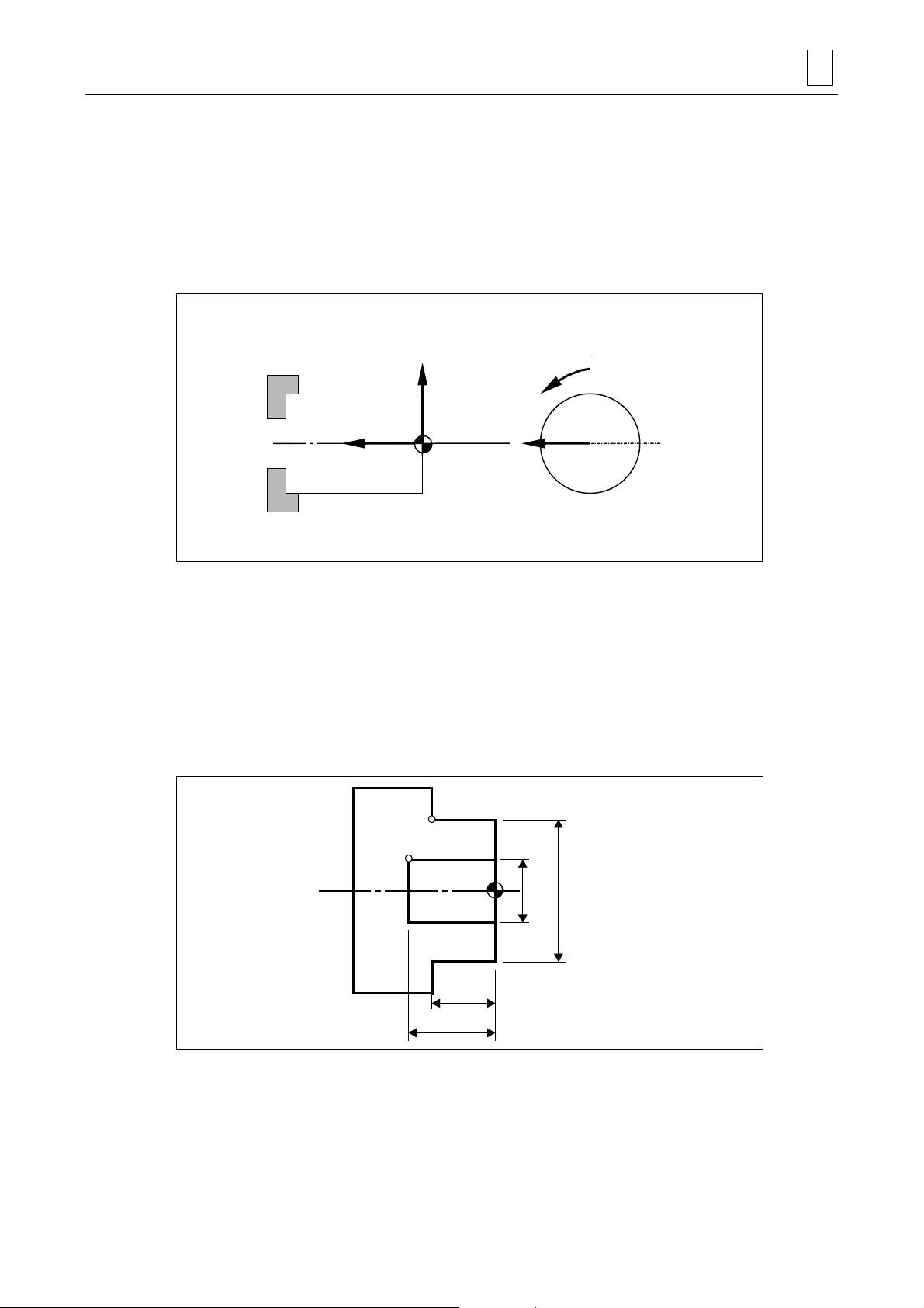
For MAZATROL programs, the following coordinate system is used to define machining patterns:
PROGRAM COORDINATE SYSTEM 2
+X
+Z
Program
origin
Program origin
+C
+Y
T3P001
The program origin of X-Z-coordinates system can be set anywhere on the center line of the
workpiece. Usually, however, the crossing point of the center line of the workpiece and its
finishing edge surface should be taken as the program origin. The program origin of C-axis
(rotational axis) can be set at any position convenient for programming. For MAZATROL
programs, set X-coordinates as diameter data. That is, the workpiece diameter indicated on the
drawing must be set as it is.
Example: For the workpiece shape shown in the diagram below:
The coordinates (x, z) of point A are (50, 20), and the coordinates (x, z) of point B
(20, 30).
B
20φ50
φ
20
30
T3P008
Note 1: For manual program machining units (MANL PRG) and facing units (FACING), the
direction of Z-axis is opposite to the one shown in the diagram above. See the relevant
items in Chapter 3 for further details.
Note 2: Refer to the sections of milling units for details on the C- and Y-axes.
2-1
Page 20

2 PROGRAM COORDINATE SYSTEM
- NOTE -
2-2
E
Page 21

3 PROGRAM CREATION
Both the program data and sequence data within a MAZATROL program must be set on the
PROGRAM display, and TPC data must be set on the TPC display. The TPC display is call ed up
from the PROGRAM display.
This chapter first describes general procedures and precautions related to creating a
MAZATROL program and then describes detailed procedures for setting each type of program
data on a unit-by-unit basis.
3-1 Procedure for Program Creation
(1) Select the PROGRAM display.
- Carry out the following operations to call up the PROGRAM display:
1) Press the display selector key.
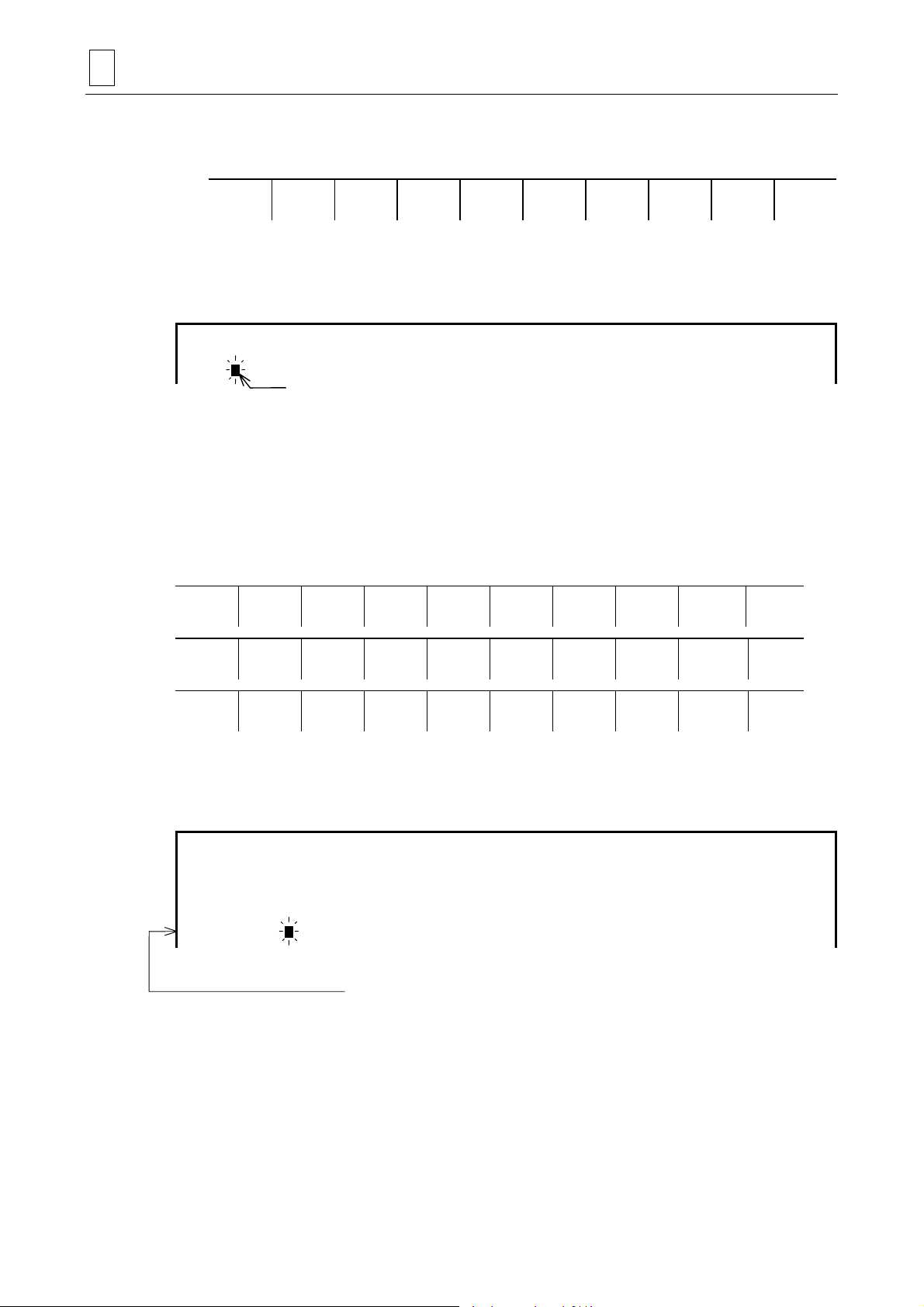
! You will then see the follo wing main -display selection me nu in the menu di splay area of
your screen:
PROGRAM CREATION 3
POSITION SET UP
INFO
PROGRAM TOOL
DATA
CUTTING
COND.
PARAM DIANOS DATA
IN/OUT
TOOL
LAYOUT
2) Press the [PROGRAM] m enu key.
! The program last selected will be displayed on the PROGRAM display and the current
menu will change over to this one:
WORK No. FIND PROGRAM BARRIER
INFORM.
WPC MSR TOOL
PATH
PROCESS
CONTROL
PROGRAM
LAYOUT
HELP PROGRAM
(2) Press the [WORK No.] menu key.
! The display of [WORK No.] becomes highlighted and the work-Nos. listing window will
be displayed.
* The work-Nos. listing window refers to a window that displays a list of work numbers of the
programs that have already been registered in the NC equipment.
(3) Set the work number of the creating program.
- A “work number” refers to a number assigned to each program to distinguish one program
from another. A combination of up to 32 alphanumeric characters: 0 to 9 and A to Z,
including the symbols “_”, “.”, “+” and “–”, can be used for a work number.
Note 1: If a work number is composed of figures alone, it should be a natural number
between 1 and 99999999.
DISPLAY
MAP
FILE
Note 2: A program name should not begin with a dot (.).
- If a work number already registered in the NC unit is set, that program will be displayed on
the screen. To create a new MAZATROL program, therefore, you must set a work number
not used in other programs.
You can check the work-Nos. listing window or the PROGRAM FILE display to see which
work numbers are not yet used
3-1
Page 22
3 PROGRAM CREATION
- If you set a work number not used for the programs that have been registered in the NC
unit, the current menu will change over to this one:
WORK No. EIA/ISO
* The EIA/ISO programming function is optional.
(4) Press the [MAZATROL PROGRAM] menu key.
! The following line will be displayed on the screen:
UNo. MAT. OD-MAX ID-MIN LENGTH WORK FACE ATC MODE RPM LTUR DIA
0
This line denotes the common unit.
(5) Set data in each item of the common unit.
- See Section 3-2, “Common Unit” for details of the data to be set.
- Each time you set data, the cursor moves to the next item automatically.
- When you set data in the last item of the common unit, the cursor will move to the starting
position of the next line and then the following menu A will be displayed, and pressing the
[ >>> ] menu key changes A → B → C → A → B → C in order.
*
PROGRAM
Cursor
MAZATROL
PROGRAM
POINT
MACH-ING
SELECT
HEAD
LINE
MACH-ING
TRANSFER
WORKPICE
FACE
MACH-ING
PROCESS
END
TURNING MANUAL
PROGRAM
M
M CODE
SUB
PROGRAM
WPC MSR WORKPICE
MEASURE
END SHAPE
CHECK
TOOL
MEASURE
SIMUL. 2 WORKPC
WORKPIECE
SHAPE
MODE
(6) From the menus A, B and C, select a unit that is to follow the common unit.
! The unit data line of the selected unit will be displayed in the screen.
Example: If you have selected the bar-materials machining unit (BAR):
UNo. MAT. OD-MAX ID-MIN LENGTH WORK FACE ATC MOCE RPM LTUR DIA
0 CBN STL 100. 0. 100. 2. 0 3000 120.
UNo. UNIT PART POS-B CPT-X CPT-Z FIN-X FIN-Z
1 BAR
↑
Cursor
This line will be displayed.
If you have selected a unit that consists of only unit data (e. g. M-code unit):
>>>
>>>
>>>
A
"""
B
"""
C
"""
(7) Set data in each item on the unit data line.
- See the relevant part of this section for further detail of the data to be set.
- Each time you set data, the cursor moves to the next item automatically.
- When you set data in the last item, the cursor will move to the beginning of the next line
(unit data line).
3-2
Page 23

PROGRAM CREATION 3
If you have selected a unit that consists of unit data, tool sequence data, and shape
sequence data of only one line (e. g. corner-machining unit):
(7)-1 Set data in each item on the unit data line.
- See the relevant part of this section for further detail of the data to be set.
- Each time you set data, the cursor moves to the next item automatically.
- When you set data in the last item, the cursor will move to the beginning of the next line
(tool sequence data line).
(7)-2 Set data in each item on the tool sequence data line.
- See the relevant part of this section for further details of the data to be set.
- Each time you set data, the cursor moves to the next item automatically.
- When you set data in the last item, the cursor will move to the beginning of the next line
(shape sequence data line).
(7)-3 Set data in each item on the shape sequence data line.
- See the relevant part of this section for further details of the data to be set.
- Each time you set data, the cursor moves to the next item automatically.
- When you set data in the last item, the cursor will move to the beginning of the next line
(unit data line).
If you have selected a unit that consists of unit data, tool sequence data, and shape
sequence data of multiple lines (e. g. bar-materials machining unit):
(7)-1 Set data in each item on the unit data line.
- See the relevant part of this section for further details of the data to be set.
- Each time you set data, the cursor moves to the next item automatically.
- When you set data in the last item, the cursor will move to the beginning of the next line
(tool sequence data line).
(7)-2 Set data in each item on the tool sequence data line.
- See the relevant part of this section for further details of the data to be set.
- Each time you set data, the cursor moves to the next item automatically.
- When you set data in the last item, the cursor will move to the beginning of the next line
(shape sequence data line).
(7)-3 Set data in each item on the shape sequence data line.
- See the relevant part of this section for further details of the data to be set.
- Each time you set data, the cursor moves to the next item automatically.
(7)-4 After you have set the entire shape sequence data, press the [SHAPE END] menu key.
- The line that immediately succeeds the last shape sequence data line will be displayed as
a unit data line.
- For a unit that permits you to set more than one line of shape sequence data, you cannot
select the next unit unless you carry out this operation (pressing the [SHAPED END]
menu key).
3-3
Page 24

3 PROGRAM CREATION
If you have selected a unit that consists of unit data, tool sequence data of multiple lines
and shape sequence data of multiple lines (e. g. drilling unit):
(7)-1 Set data in each item on the unit data line.
- See the relevant part of this section for further details of the data to be set.
- Each time you set data, the cursor moves to the next item automatically.
- When you set data in the last item, the tool sequence data is made automatically and the
cursor will move to the beginning of the tool sequence data line.
(7)-2 Set data in each item on the tool sequence data line.
- See the relevant part of this section for further details of the data to be set.
- Each time you set data, the cursor moves to the next item automatically.
(7)-3 After you have set the entire tool sequence data, set data in each item on the shape
sequence data line.
- See the relevant part of this section for further details of the data to be set.
- Each time you set data, the cursor moves to the next item automatically.
(7)-4 After you have set the entire shape sequence data, press the [SHAPE END] menu key.
- The line that immediately succeeds the last shape sequence data line will be displayed as
a unit data line.
- For a unit that permits you to set more than one line of shape sequence data, you cannot
select the next unit unless you carry out this operation (pressing the [SHAPED END]
menu key).
(8) Select the units required for the intended machining operation by repeating steps (6) and (7)
above (including steps (7)-1, (7)-2, (7)-3 and (7)-4), and then set data in each of the items
displayed on the screen.
- A selectable unit differs according to the type of product to be machined. Select a unit in
the most suitable order in accordance with your machining drawing, unit sheet, etc.
After unit selection, the program can be generated just by setting data as guided by
messages.
(9) Set the end unit at the end of the program.
- Press the [END] menu key.
- Without the end unit, the program will not be regarded as a complete one. Therefore, you
must set the end unit at the last line of the program.
(10) Set data in each item of the end unit.
- See the section “End Unit (END)” for details of the data to be set.
Note 1: One MAZATROL program can contain a maximum of 1000 units, including the
common unit and the end unit. For units that allow you to set multiple lines of sequence
data, up to a maximum of 200 lines of shape sequence data can be regi ste red per unit.
Note 2: The shape data that you have set can be checked for errors by calling up the SHAPE
CHECK display while you are creating the program. See the Operating Manual for
details.
3-4
Page 25

Note 3: For the following units, TPC data can be set as required:
Turning
- BAR unit
- CPY unit
- CORNER unit
- FACING unit
- THREAD unit
- T. GROOVE unit
- T. DRILL unit
- T. TAP unit
- MILLTURN unit
Other units
- MMS unit
- WORK MES unit
- TOOL MES unit
- TRANSFER unit
Milling
- DRILLING unit
- RGH CBOR unit
- RGH BCB unit
- REAMING unit
- TAPPING unit
- BK-CBORE unit
- CIRC MIL unit
- CBOR-TAP unit
- BORE T1 unit
- BORE S1 unit,
- BORE T2 unit
- BORE S2 unit
- LINE CTR unit
- LINE RGT unit
- LINE LFT unit
- LINE OUT unit
- LINE IN unit
- CHMF RGT unit
- CHMF LFT unit,
- CHMF OUT unit
- CHMF IN unit
- FCE MILL unit
- TOP EMIL unit
- STEP unit
- POCKET unit
- PCKT MT unit
- PCKT VLY unit
- SLOT unit
PROGRAM CREATION 3
See “TPC DATA SETTING” for further details of the data to be set.
3-5
Page 26
3 PROGRAM CREATION
[4]
3-2 Common Unit
The common unit is the first to be placed in a MAZATROL program, and always takes unit
number 0.
Data that is set in this unit is referred to as common data, which becomes the base data for the
entire program. When creating a MAZATROL program, therefore, you must first set data in this
unit.
3-2-1 Setting unit data (common data)
UNo. MAT. OD-MAX ID-MIN LENGTH WORK FACE ATC MODE RPM LOW TURR
0 [1] [2] [3] [4] [5] [6] [7] [8]
[1] MAT
The following menu will be displayed when the cursor is placed at this item:
CST IRN DUCT IRN CBN STL ALY STL STNLESS ALUMINUM L.C.STL AL CAST
From the menu, select the materials type of the workpiece to be machined.
If the workpiece to be machined is of a materials type other than those listed above, pre-register
that materials type on the CUTTING CONDITION - PERCENTAGE display. See the Operating
Manual for details.
The data of this item is referred to by the system during automatic setting of cutting conditions.
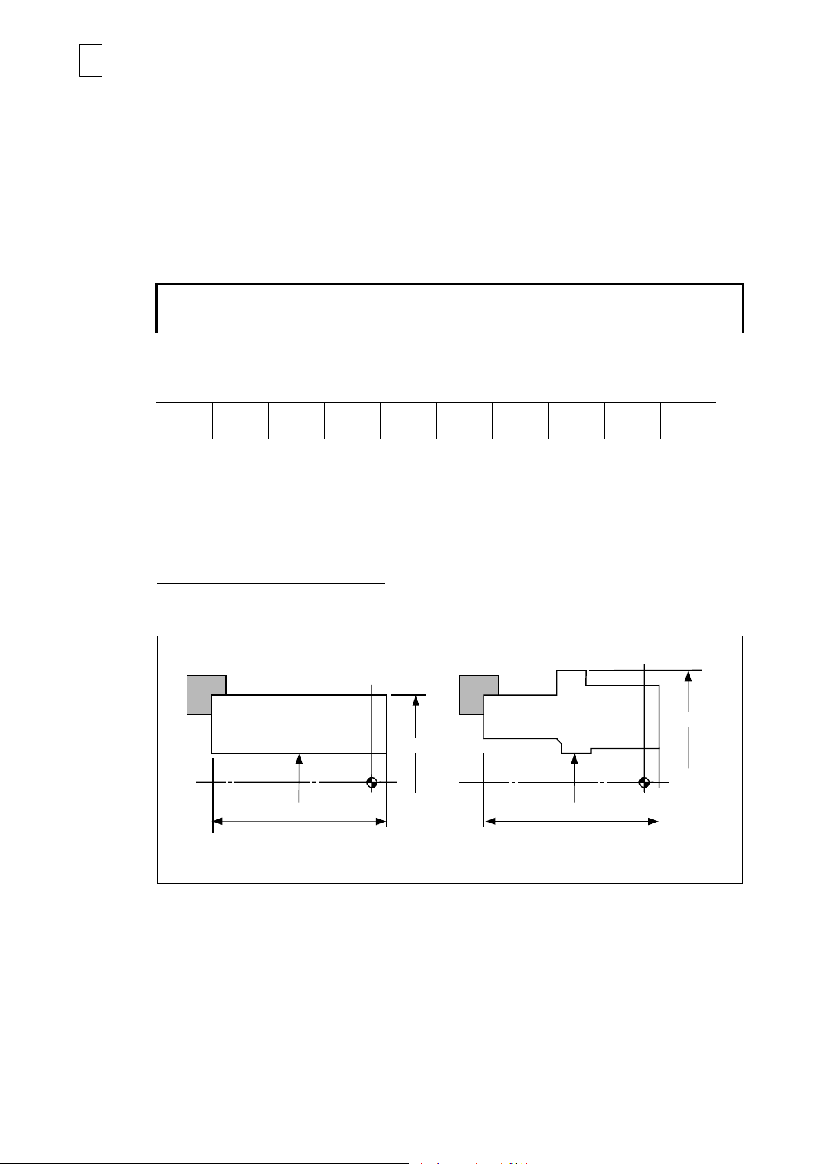
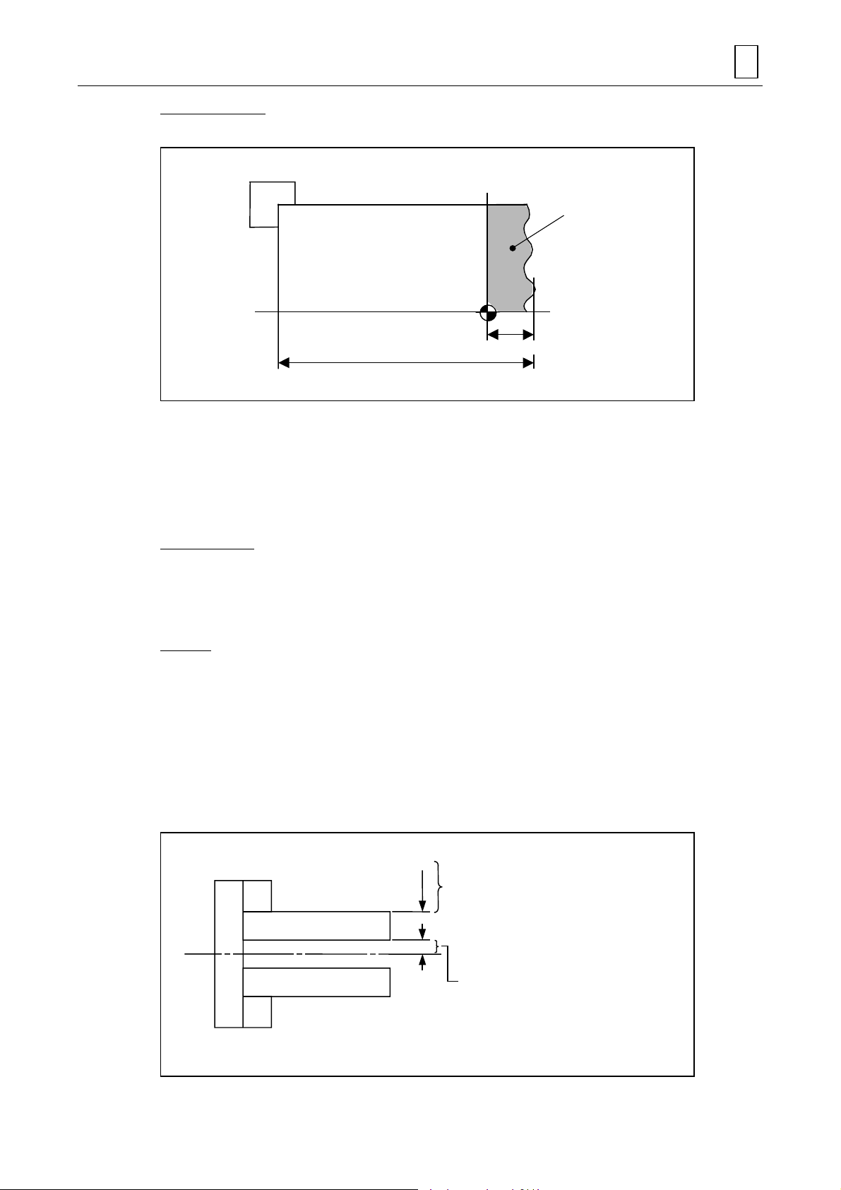
[2] OD-MAX, [3] ID-MIN, [4] LENGTH
Set the maximum outside diameter, minimum inside diameter, and maximum length, respectively,
of the workpiece.
[2] OD-MAX
[2] OD-MAX
Program
origin
T4P017
[3] ID-MIN
[4] LENGTH
Round bar materials
Program
origin
[3] ID-MIN
LENGTH
Molded materials
- Set the workpiece length, including the edge protrusion (edge section to be cut), in item [4].
3-6
Page 27
PROGRAM CREATION 3
[5] WORK FACE
Set the length of the workpiece edge protrusion in the Z-axis direction.
Protrusion
Program origin
[4] LENGTH
[5] WORK FACE
T4P019
- The workpiece edge protrusion refers to a section to be cut during a facing unit (FACING
FACE).
For units other than facing units, the protrusion is not regarded as part of the workpiece.
Therefore, if the workpiece edge is to be cut (that is, if a value other than 0 is set for this item),
an facing unit must be selected before selecting a unit involving other machining operations.
Either 0 or a plus value must always be set for this item.
[6] ATC MODE
Specify how to retract the axes before ATC.
- Enter 0 to move the axes one by one from the machining end point to the ATC position.
- Enter 1 to move the axes all together from the machining end point to the ATC position.
[7] RPM
If the maximum spindle speed is to be limited, set that maximum value. Data does not need be
set if the spindle speed is permitted to reach the maximum value provided for in the
specifications.
This data has no relation to the milling axial velocity.
Note: For an X-axial tool-tip position over OD-MAX or under ID-MIN (both specified in the
common unit), constant cutting speed control will opportunely be relieved by the
constant spindle speed control for extra-workpiece area and the spindle will rotate at
the speed calculated for the position of OD-MAX or ID-MIN.
The spindle speed for this area is downwards
limited to the value c al culated for OD-MAX.
OD-MAX
ID-MIN
The spindle speed for this area is upwards
limited to the value c al culated for ID-MIN.
* Constant surface speed control is cancelled for extra-workpiece
area in order to reduce the machining time.
3-7
Page 28

3 PROGRAM CREATION
[8] LOW TURR
For a machine equipped with upper and lower turrets, enter a safe outside -diameter value for the
lower turret. See Chapter 5, “LOWER-TURRET CONTROL FUNCTIONS”, for further details.
3-3 Materials Shape Unit (MATERIAL)
The shapes of cast materials or forged materials cannot be defined using the common unit alone.
To machine such molded materials, the materials shape unit must be selected following the
common unit and the shape data of the materials to be machined must be set.
Only the outside-diameter shape and inside-diameter shape of the intended workpiece can be
defined using the materials shape unit. This unit of base data, therefore, has no relation to units
of machining on the front and back faces, since the tool path for such units are created merely on
the basis of the settings in the common unit.
This unit need not be set for round-bar materials.
Press the [WORKPICE SHAPE] menu key to select the materials sha pe unit.
3-3-1 Setting unit data
UNo. UNIT
∗ MATERIAL [1]
[1] UNIT
The following menu will be displayed when the cursor is placed at this item.
OUT IN
- Select [OUT] to define the outside-diameter shape of the workpiece.
- Select [IN] to define the inside-diameter shape of the workpiece.
Both OUT and IN can be defined using a maximum of 25 sequences.
You must first select [OUT], however, when defining both the outside-diameter and insidediameter shapes of a workpiece. That is, after selecting the materials shape unit a s both units No.
1 and No. 2, define the outside-diameter shape using unit No. 1 and then define the insidediameter shape using unit No. 2.
3-3-2 Setting sequence data
UNo. UNIT
∗ MATERIAL ∗∗∗
FIG PTN SPT-X SPT-Z FPT-X FPT-Z RADIUS
1 [1] [2] [3] [4] [5] [6]
[1] PTN
The following menu will be displayed when the cursor is placed at this item.
LIN TPR SHAPE
Select the type of shape from the above menu.
3-8
END
Page 29
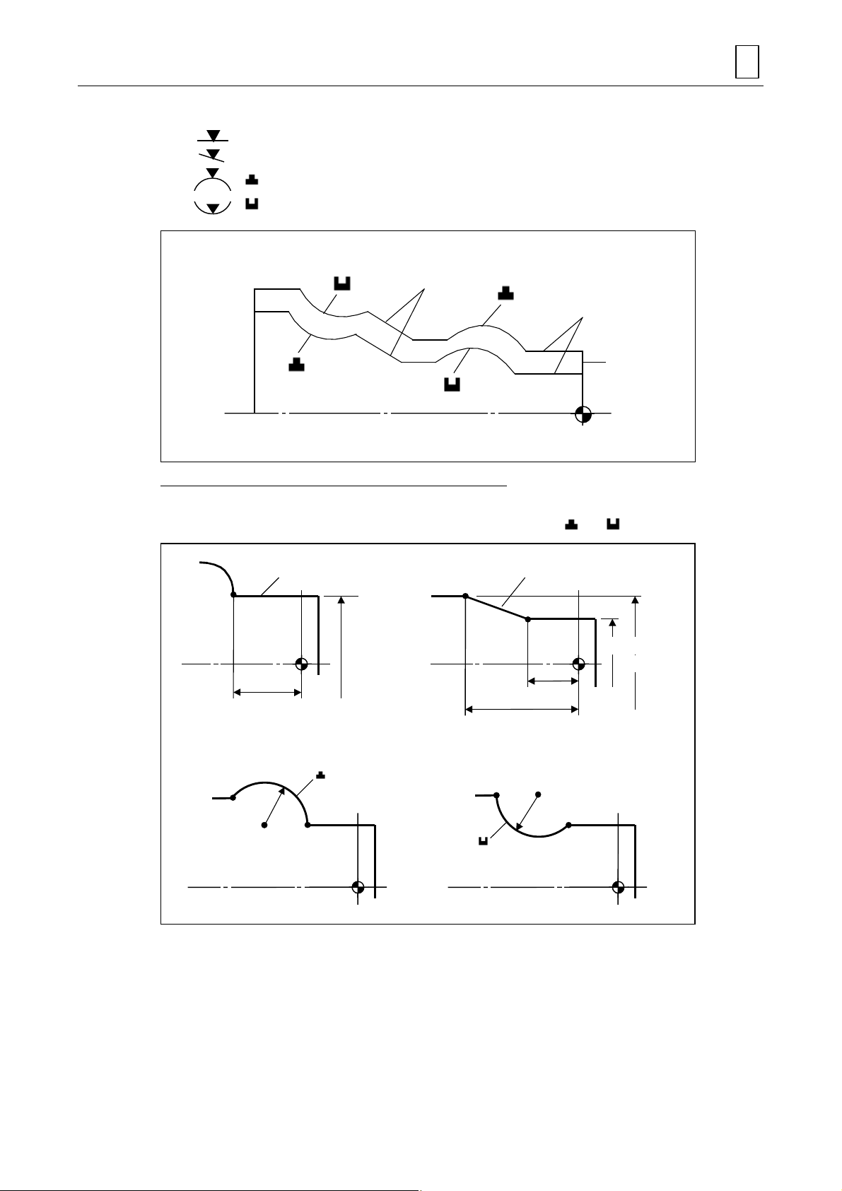
The data of the displayed menu denote the following shapes:
PROGRAM CREATION 3
LIN : Line parallel to the center line of the workpiece
TPR : Line not parallel to the center line of the workpiece (Taper line)
: Convex arc
:Concave arc
Outer diameter
shape
Inner diameter
shape
TPR
LIN
Material shape
T4P021
[2] SPT-X, [3] SPT-Z, [4] FPT-X, [5] FPT-Z, [6] RADIUS
Set the coordinates of the intended start point and end point of the shape you selected for item
[1]. Also set the radius of the desired circle if you have selected
or .
LIN
End
point
[4] FPT-X
[5] FPT-Z
End
point
[6] RADIUS
Start
point
End
point
TPR
Start point
[2] SPT-X
[4] FPT-X
[3] SPT-Z
[5] FPT-Z
End
point
[6] RADIUS
Start
point
T4P023
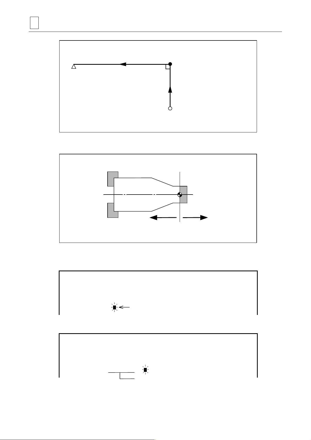
- If you have selected [LIN] for item [1] above, it is good enough just to designate only the
coordinates of the end point (FPT-X and -Z). This is because the NC unit will then form
automatically two orthogonal lines between the end point of the immediately preceding shape
(or the program origin for an LIN as the first shape) and that end point.
3-9
Page 30
3 PROGRAM CREATION
End point
Note 1: The Z-coordinates of any points located to the right of the program origin must be set
Start point
(The coordinates do not need to be set. )
End point of imm edi at el y preceding shape
T4P022
with a minus sign.
Plus data Minus data
T4P024
Note 2: If the start point of a shape is present in the same position as that of the end point of
the immediately preceding shape, those coordinates can be automatically set by
pressing the [NEXT] menu key.
UNo. UNIT
1 MATERIAL OUT
FIG PTN SPT-X SPT-Z FPT-X FPT-Z RADIUS
1
2
LIN
TPR
##20. 30. #
Cursor
#
Pressing the [NEXT] menu key with the cursor at the position shown above sets the
following data automatically:
UNo. UNIT
1 MATERIAL OUT
FIG PTN SPT-X SPT-Z FPT-X FPT-Z RADIUS
1
2
LIN
TPR
#
20.#30.
20. 30. #
#
These values are set automatically.
You can use this function also for BAR and CPY units.
3-10
Page 31

PROGRAM CREATION 3
Note 1: Although a maximum of 200 lines of shape sequence data can be set in one materials
shape unit or turning unit, the maximum usable number of shape sequence data lines
may be less than 200 when corner R/C is defined for a complex shape. In that case,
alarm 723 EXCEEDS NUMBER OF SHAPES will be displayed, even before the
maximum usable number of shape sequence data lines is reached.
Note 2: If the maximum usable number of shape sequence data lines is exceeded, alarm 723
EXCEEDS NUMBER OF SHAPES will be displayed during tool path checking, shape
checking, shape drawing, or automatic operation.
3-11
Page 32

3 PROGRAM CREATION
3-4 Types of the Milling Unit
The milling unit is available in the following three types :
- Point machining unit ...... used for drilling of holes (Section 3-5)
- Line machining unit ........ used for a contour machining (Section 3-6)
- Face machining unit ...... used for machining an area and machining form (Section 3-7)
Each milling unit includes tool sequence and shape sequence.
3-4-1 Planes to be machined and machining methods
Data items for setting the plane to be machined and for setting the machining method exist in all
point, linear, and face machining unit data. These data items are displayed as MODE, POS-B,
and POS-C.
Specify the desired face and method under the MODE, POS-B, and POS-C columns.
UNo. UNIT MODE POS-B POS-C DIA DEPTH CHMF
DRILLING
[1] MODE
[1] [2] [3]
Select the machining method.
Mode Description
Cylindrical sides can be machined into the desired shape as specified in the Z-C coordinate
system.
(C-axial machining)
ZC
Edges can be machined into the desired shape as specified in the R-C or X-Y coordinate system.
(C-axial machining)
XC
C
C
If C-axis function for No. 2 spindle is
Note:
available, the line machining can be
executed on the No. 2 spindle as well.
C
XC
Rear plane can be machined into the desired shape as specified in the R-C or X-Y coordinate
system.
(C-axial machining)
C
Note: The line machining is possible only if
the machine has C-axis function for
No. 2 spindle.
3-12
Page 33

Mode Description
Plane of cylinder can be machined into the desired shape as specified in the Z-Y coordinate
system.
(Y-axial machining)
PROGRAM CREATION 3
ZY
XY
XY
Z
Y
Edges can be machined into the desired shape as specified in the X-Y or R-C coordinate system.
(Y-axial machining)
X
Y
Rear plane can be machined into the desired shape as specified in the X-Y or R-C coordinate
system.
(Y-axial machining)
X
Y
/C
/C
/Y
Holes can be machined on an oblique plane at the desired oblique positioning angle as specified
in the B-axial direction. (C-axial machining)
This mode cannot be selected for the line or plane machining units.
C
The tool approaches from the edge side.
Holes can be machined on an oblique plane at the desired oblique positioning angle as specified
in the B-axial direction. (C-axial machining)
This mode cannot be selected for the line or plane machining units.
C
The tool approaches from the rear side.
Holes can be machined on an oblique plane at the desired oblique positioning angle as specified
in the B-axial direction. (Y-axial machining)
The tool approaches from the edge side.
3-13
Page 34

3 PROGRAM CREATION
Mode Description
/Y
The XC , XY , /C , /Y mode can be selected for a machine model capable of back
machining.
Holes can be machined on an oblique plane at the desired oblique positioning angle as specified
in the B-axial direction. (Y-axial machining)
The tool approaches from the rear side.
Note: For the line machining unit, the /C or /C
/C or /C
Precautions for milling with the lower turret
1. The machine operates in single-workpiece independent machining mo de.
2. The machine operates only in point-machining mode.
Drilling, inverse faced hole machining, reaming, tapping, and boring (see Note 2 below) are
possible (see Note 1 below).
Counterbore machining, back boring, circular milling, or counterbore-tapping i s impossible.
3. It is possible to use ZC, XC, or XC
It is not possible to use /C, /C
4. The machine does not operate in line- or face-machining mode.
5. The lower turret cannot be used for the M-MANUAL unit that operates the Y-axis.
6. Simultaneous machining with the milling tools mounted in the upper and lower turrets is
impossible.
Note 1: Machining that requires Y-axis operation results in an alarm (for chamfering cycle 2).
Note 2: Boring cycle 1 and 2 cannot be used (an alarm occurs for lower-turret milling spindle
orientation).
mode cannot be selected for a face machining unit.
mode. (See Note 1.)
, ZY, XY, XY , /Y, or /Y mode.
mode cannot be selected. The ZC, XC, XC ,
[2] POS-B
When machining an oblique plane, specify angle B of the oblique plane with respect to a
reference angle of 0 degrees of the edge.
This data item will become valid when the /C, /Y, /C
having a B-axis.
[3] POS-C
Specify the position of the C-axis.
This data item will become valid when the ZY, XY, XY
3-14
, /Y mode is selected for a machine model
, /Y, /Y mode is selected.
Page 35

3-5 Point Machining Units
The point machining unit serves to determine the data concerning the machining method and
machining form for the drilling of holes.
The unit includes the tool sequence determining the tool data used and the shape sequence
determining the data concerning the machining dimensions on the drawing.
3-5-1 Types of point machining units
As shown below 12 types of point machining units are available:
PROGRAM CREATION 3
1. Drilling 2. Counterbore machining
NM210-00532
5. Tapping 6-(1) Boring of through hole
NM210-00533 NM210-00534 NM210-00535
3. Inversed faced hole
machining
6 (2) Boring of non-
through hole
4. Reaming
6 (3) Boring of stepped
through hole
NM210-00536
6-(4) Boring of stepped
non-through hole
NM210-00540 NM210-00541 NM210-00542 NM210-00543
Fig. 3-1 Types of point machining units
NM210-00537
7. Back boring 8. Circular milling 9. Counterbore-tapping
NM210-00538
NM210-00539
3-15
Page 36

3 PROGRAM CREATION
3-5-2 Procedure for selecting point machining unit
(1) Press the menu selector key (key located at the right of the menu keys) to display the
following menu.
POINT
MACH-ING
LINE
MACH-ING
FACE
MACH-ING
TURNING MANUAL
PROGRAM
END SHAPE
CHECK
>>>
(2) Presse the [POINT MACH-ING] menu key.
! The following unit menu will be displayed.
DRILLING RGH CBOR RGH BCB REAMING TAPPING BORING BK CBOR CIRC MIL CBOR TAP HI SPD.
DRL.USE
(3) Press the appropriate menu key of the desired machining unit.
- When the [BORING] menu key is pressed, the menu of the four following machining subunits is displayed.
BORING BORING BORING BORING
Remark: For the function of the [HI SPD. DRL. USE] menu key, refer to the Subsection 3-5-4,
“Automatic tool development for cemented carbide drills”.
3-16
Page 37

PROGRAM CREATION 3
3-5-3 Unit data and automatic tool development of the point machining unit
1. Drilling unit (DRILLING)
Select this drilling unit for machining of a hole with a drill.
DRILLING unit Tool sequence
DIA
CHMF
DEPTH
Centering drill
M3P085 D740PA030
The tools in parentheses ( ) are developed or not developed depending on the particular case.
Drill (Drill) (Drill)
(Chamfering cutter)
Automatic tool development
The tools are automatically developed according to different patterns on the basis of the data
entered in the unit. The machining is executed on the basis of the tool sequence data and the
unit data are not used for the machining. If the data developed are inappropriate for the
machining, edit by modifying the data or deleting the tool.
Tool Development patterns
Centering drill Development is always executed.
A maximum of three tools are developed depending on the diameter of the hole.
0
Drill
Chamfering cutter
< DIA ≤ D8: Development of one tool
D8 < DIA ≤ D9: Development of two tools
D9 < DIA ≤ D10: Development of three tools
Development is not executed in the following cases:
DIA + (CHMF × 2) ≤ D2 – D4
CHMF = 0
The bold codes represent parameter addresses.
Note: In the following cases the alarm 416 AUTO PROCESS IMPOSSIBLE will be displayed.
- DEPTH < CHMF
- DIA = 0
- D10 < DIA
3-17
Page 38

3 PROGRAM CREATION
2. Counterbore machining unit (RGH CBOR)
This unit is selected for machining a hole with a counterbore (faced hole).
RGH CBOR unit Tool sequence
CB-DIA
CB-DEP
CHAMF
DIA
The tools in parentheses ( ) are developed or not developed depending on the particular case.
DEPTH
Centering drill Drill (Drill) (Drill) End mill (Chamfering
cutter)
M3P087 D740PA031
Automatic tool development
The tools are automatically developed according to different patterns on the basis of the data
entered in the unit. The machining is executed on the basis of the tool sequence data and the
unit data are not used for the machining. If the data developed are inappropriate for the
machining, edit by modifying the data or deleting the tool.
Tool Development patterns
Centering drill Development is always executed.
A maximum of three tools are developed depending on the diameter of the hole.
0 < DIA
Drill
End mill Development is always executed.
Development is not executed in the following casses:
Chamfering cutter
≤ D8: Development of one tool
D8 < DIA ≤ D9: Development of two tools
D9 < DIA ≤ D10: Development of three tools
CHMF = 0
DIA + (DEPTH × 2)
≥ CB-DIA + (CHMF × 2) < D13
The bold codes represent parameter addresses.
Note: In the following cases the alarm 416 AUTO PROCESS IMPOSSIBLE will be displayed.
- CB-DIA < DIA
- DEPTH < CB-DEP
- DEPTH < CHMF
3-18
Page 39

3. Inversed faced hole machining unit (RGH BCB)
This unit is selected for machining a hole with an inversed faced hole.
RGH BCB unit Tool sequence
DIA
PROGRAM CREATION 3
CHMF
CB-DIA
DEPTH
CB-DEP
M3P089 D740PA032
The tools in parentheses ( ) are developed or not developed depending on the particular case.
Centering drill Drill (Drill) Back facing(Drill) (Chamfering
cutter)
Automatic tool development
The tools are automatically developed according to different patterns on the basis of the data
entered in the unit. The machining is executed on the basis of the tool sequence data and the
unit data are not used for the machining. If the data developed are inappropriate for the
machining, edit by modifying the data or deleting the tool.
Tool Development patterns
Centering drill Development is always executed.
A maximum of three tools are developed depending on the diameter of the hole.
0 < DIA
Drill
Development is not executed in the following cases:
Chamfering cutter
Back facing tool Development is always executed.
≤ D8: Development of one tool
D8 < DIA ≤ D9: Development of two tools
D9 < DIA ≤ D10: Development of three tools
DIA + (CHMF × 2)
CHMF = 0
≤ D2 – D4
The bold codes represent parameter addresses.
Note: In the following cases the alarm 416 AUTO PROCESS IMPOSSIBLE will be displayed.
- CB-DIA < DIA
- DEPTH < CB-DEP
- DEPTH < CHMF
3-19
Page 40

3 PROGRAM CREATION
4. Reaming unit (REAMING)
Select this unit for performing finish machining with reamer.
In reaming, the content of the tool sequence to be set is different according to the preceding
process.
A. Case of preceding process = drilling
REAMING unit Tool sequence
DIA
CHMF
DEPTH
Centering drill
M3P091 D740PA033
The tools in parentheses ( ) are developed or not developed depending on the particular case.
Drill
(Drill) (Drill)
(Chamfering cutter)
Reamer
Automatic tool development
The tools are automatically developed according to different patterns on the basis of the data
entered in the unit. The ma chining is executed on th e basis of the tool sequenc e data and the
unit data are not used for the machining. If the data developed are inappropriate for the
machining, edit by modifying the data or deleting the tool.
Tool Development patterns
Centering drill Development is always executed.
A maximum of three tools are developed depending on the diameter of the hole.
Drill
Chamfering cutter
Reamer Development is always executed.
0 < DIA –
D8 < DIA – D35 ≤ D9: Development of two tools
D9 < DIA – D35 ≤ D10: Development of three tools
Development is not executed in the following cases:
DIA + (CHMF × 2)
CHMF = 0
D35 ≤ D8: Development of one tool
≤ D2 – D4
The bold codes represent parameter addresses.
Note: In the following case the alarm 416 AUTO PROCESS IMPOSSIBLE will be displayed.
- DEPTH < CHMF
3-20
Page 41

B. Case of preceding process = boring
REAMING unit Tool sequence
DIA
PROGRAM CREATION 3
CHMF
DEPTH
Centering drill
(Chamfering
cutter)
M3P093 D740PA034
The tools in parentheses ( ) are developed or not developed depending on the particular case.
Drill
Reamer
(Drill) (Drill)
Boring
Automatic tool development
The tools are automatically developed according to different patterns on the basis of the data
entered in the unit. The machining is executed on the basis of the tool sequence data and the
unit data are not used for the machining. If the data developed are inappropriate for the
machining, edit by modifying the data or deleting the tool.
Tool Development patterns
Centering drill Development is always executed.
A maximum of three tools are developed depending on the diameter of the hole.
Drill
Boring tool Development is always executed.
Chamfering cutter
Reamer Development is always executed.
0 < DIA –
D8 < DIA – D36 ≤ D9: Development of two tools
D9 < DIA – D36 ≤ D10: Development of three tools
Development is not executed in the following cases:
DIA + (CHMF × 2) ≤ D2 – D4
CHMF = 0
D36 ≤ D8: Development of one tool
The bold codes represent the parameter addresses.
Note: In the following case the alarm 416 AUTO PROCESS IMPOSSIBLE will be displayed.
- DEPTH < CHMF
3-21
Page 42

3 PROGRAM CREATION
C. Case of preceding process = end mill
REAMING unit Tool sequence
DIA
CHMF
DEPTH
Centering drill Drill (Drill) (Drill) End mill
End mill
M3P095 D740PA035
The tools in parentheses ( ) are developed or not developed depending on the particular case.
(Chamfering
cutter)
Reamer
Automatic tool development
The tools are automatically developed according to different patterns on the basis of the data
entered in the unit. The machining is executed on the basis of the tool sequence data and the
unit data are not used for the machining. If the data developed are inappropriate for the
machining, edit by modifying the data or deleting the tool.
Tool Development patterns
Centering drill Development is always executed.
A maximum of three tools are developed depending on the diameter of the hole.
Drill
End mill Development of two tools is executed.
Chamfering cutter
Reamer Development is always executed.
0 < DIA –
D8 < DIA – D37 ≤ D9: Development of two tools
D9 < DIA – D37 ≤ D10: Development of three tools
Development is not executed in the following cases:
DIA + (CHMF × 2)
CHMF = 0
D37 ≤ D8: Development of one tool
≤ D2 – D4
The bold codes represent the parameter addresses.
Note: In the following case the alarm 416 AUTO PROCESS IMPOSSIBLE will be displayed.
- DEPTH < CHMF
3-22
Page 43

5. Tapping unit (TAPPING)
Select this unit for performing tapping.
<Setting the nominal diameter of unified thread>
Example 1: For 3/4-16 unified thread:
Press the [Q (1/4) QUARTER] menu key, and then press the keys
3 – 1 6
and
Example 2: For 1 1/8-7 unified thread:
Press the [E (1/8) EIGHTH] menu key, and then press the keys
in this order.
INPUT
<Setting the nominal diameter of pipe thread>
Example 1: For PT 3/8 thread:
Press the [E (1/8) EIGHTH] menu key, and then press the keys
in this order.
Example 2: For PF 1 thread:
Press the keys
1
and
in this order.
INPUT
in this order.
INPUT
PROGRAM CREATION 3
9 – 7
3
and
and
INPUT
Note 1: The thread depths of PT screws or PS screws are set automatically according to
MAZAK specifications.
Note 2: For planetary tapping, the data to be set for the MAJOR-φ, PITCH, TAP-DEP, and
CHMF, depends on the selected type of tool. Enter the data specified in the
corresponding tool catalogue.
For TAP-DEP, enter the cutting edge length specified in the tool catalogue.
Also, set the tool data as follows.
- Enter the catalogued nominal diameter in the tool data item ACT-φ.
- Enter the catalogued thread outside diameter in the tool data item DIAMETER.
- Enter the catalogued cutting edge length in the tool data item LENGTH.
Cutting edge length
Thread outside diameter
3-23
Page 44

3 PROGRAM CREATION
TAPPING unit Tool sequence
MAJOR-
φ
CHMF
PITCH
TAP-
DEP
Centering d rill Drill (Drill) (Drill) (Chamfering cutter) Tap
M3P097 D740PA036
The tools in parentheses ( ) are developed or not developed depending on the particular case.
Automatic tool development
The tools are automatically developed according to different patterns on the basis of the data
entered in the unit. The machining is executed on the basis of the tool sequence data and the
unit data are not used for the machining. If the data developed are inappropriate for the
machining, edit by modifying the data or deleting the tool.
Tool Development patterns
Centering drill Development is always executed.
A maximum of three tools are developed depending on the diameter of the hole.
Drill
Chamfering cutter
Tap Development always takes place.
0 < Diameter of pre-hole dr illing
D8 < Diameter of pre-hole drilling ≤ D9: Development of two tools
D9 < Diameter of pre-hole drilling ≤ D10: Development of three tools
Development is not executed in the following cases:
Diameter of hole + (CHMF × 2) ≤ D2 – D4
CHMF = 0
≤ D8: Development of one tool
The bold codes represent the parameter addresses.
Note: In the following cases the alarm 416 AUTO PROCESS IMPOSSIBLE will be displayed.
- TAP-DEP < CHMF
- Case of designation of threading other than the JIS standard threading (however, this
can be used for forced insertion).
3-24
Page 45

PROGRAM CREATION 3
6. Boring unit (BORING)
The boring has the four units as the through hole boring, non-through hole boring, stepped
through hole boring and stepped non-through hole boring.
A. Through hole boring unit (BORE T1)
Select this unit for performing through-hole boring.
BORE T1 unit Tool sequence
DIA
CHMF
DEPTH
Centering drill Drill
(Chamfering cutter)
M3P099 D740PA037
The tools in parentheses ( ) are developed or not developed depending on the particular case.
(Boring)
(End mill) Boring (Boring)
Automatic tool development
The tools are automatically developed according to different patterns on the basis of the data
entered in the unit. The machining is executed on the basis of the tool sequence data and the
unit data are not used for the machining. If the data developed are inappropriate for the
machining, edit by modifying the data or deleting the tool.
Tool Development patterns
Centering drill Development is always executed.
Drill Development is always executed.
End mill
Boring tool
Chamfering cutter
Development is not executed in the following case:
DIA – 6.0 <
Development of a maximum of three tools is executed depending on the wall roughness.
Wall roughness = 1, 2: Development of one tool
Wall roughness = 3, 4: Development of two tools
Wall roughness = 5, 6, 7, 8, 9: Development of three tools
Development is not executed in the following case:
CHMF = 0
D8
The bold codes represent the parameter addresses.
Note: In the following cases the alarm 416 AUTO PROCESS IMPOSSIBLE will be displayed.
- Diameter of faced hole < DIA
- DEPTH < Depth of faced hole
- DEPTH < CHMF
3-25
Page 46

3 PROGRAM CREATION
B. Non-through hole boring unit (BORE S1)
Select this unit for performing boring of non-through holes.
BORE S1 unit Tool sequence
DIA
CHMF
PRE-DIA
DEPTH
Centering drill Drill
(Chamfering cutter)
M3P0101 D740PA037
The tools in parentheses ( ) are developed or not developed depending on the particular case.
(Boring)
(End mill) Boring (Boring)
Automatic tool development
The tools are automatically developed according to different patterns on the basis of the data
entered in the unit. The machining is executed on the basis of the tool sequence data and the
unit data are not used for the machining. If the data developed are inappropriate for the
machining, edit by modifying the data or deleting the tool.
Tool Development patterns
Centering drill Development is always executed.
Drill Development is always executed.
Development is not executed if the following three conditions are fulfilled:
End mill
Boring tool
Chamfering cutter
DIA – 6.0 <
10.0 < PRE-DIA
DIA – PRE-DIA
The development of a maximum of three tools is executed according to the wall
roughness.
Wall roughness = 1, 2: Development of one tool
Wall roughness = 3, 4: Development of two tools
Wall roughness = 5, 6, 7, 8, 9: Development of three tools
Development does not take place in the following case:
CHMF = 0
D8
≤ 6.0
The bold codes represent the parameter addresses.
Note: The alarm 416 AUTO PROCESS IMPOSSIBLE is given in the following cases:
- DIA < PRE-DIA
- DIA ≤ 6.0
- DEPTH < CHMF
- PRE-DIA = 0 → DEPTH < (A/3.328558 – D12)
- PRE-DIA ≠ 0 → DEPTH < (A – PRE-DIA)/3.328558
A: DIA – 6.0 (in case of DIA – 6.0 < D8) or
A:
D8 (in case of D8 ≤ DIA – 6.0)
3-26
Page 47
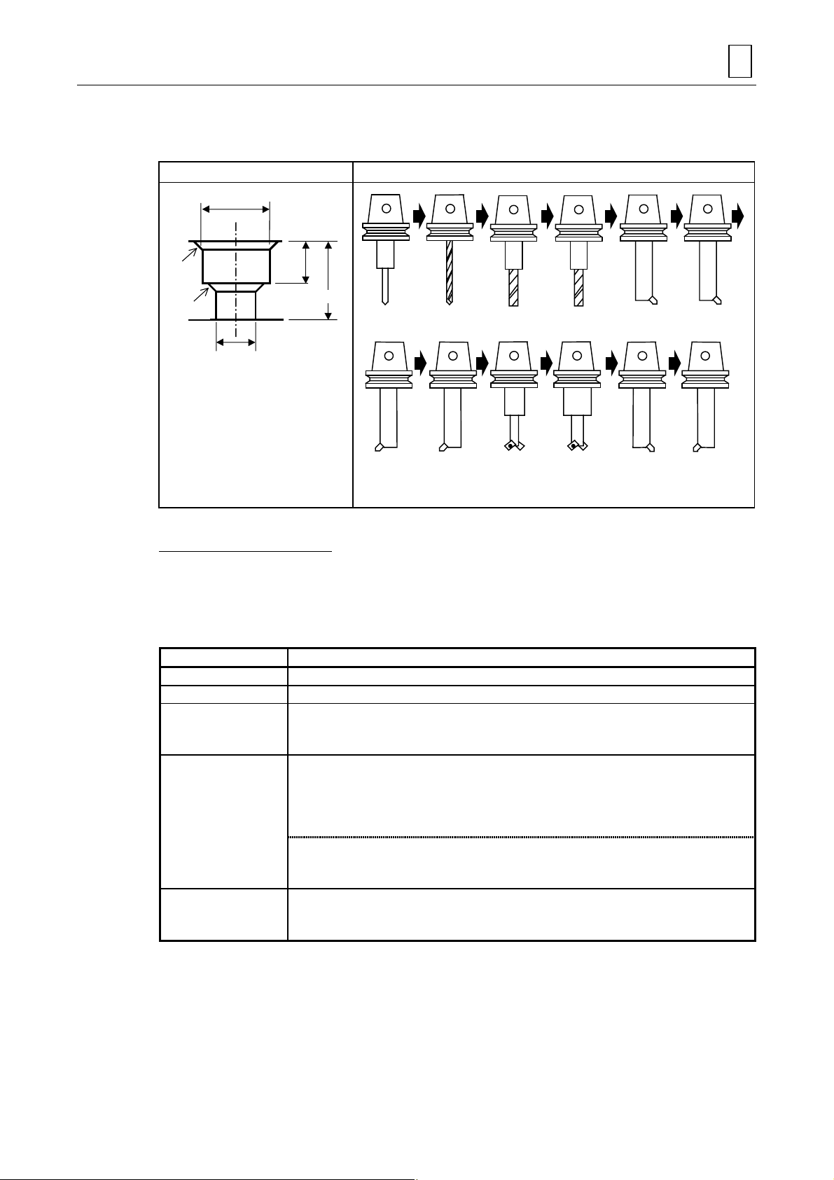
C. Stepped through hole boring unit (BORE T2)
Select this unit for performing stepped through hole boring.
BORE T2 unit Tool sequence
CB-DIA
CB-DEP
CHMF
PROGRAM CREATION 3
CHMF
DIA
DEPTH
Centering
drill
Boring (Chamfering
M3P0102 D740PA038
The tools in parentheses ( ) are developed or not developed depending on the particular case.
Drill End mill Boring
(Boring) (Boring)
cutter)
(End mill) (Boring)
(Chamfering
cutter)
(Boring)
Automatic tool development
The tools are automatically developed according to different patterns on the basis of the data
entered in the unit. The machining is executed on the basis of the tool sequence data and the
unit data are not used for the machining. If the data developed are inappropriate for the
machining, edit by modifying the data or deleting the tool.
Tool Development patterns
Centering drill Development is always executed.
Drill Development is always executed.
Development of a maximum of two tools is executed depending on the diameter of the hole.
End mill
Boring tool
Chamfering cutter
0 < DIA – 6.0 < D8: Development of one tool
D8 < DIA – 6.0 ≤ 999.999: Development of two tools
The development of a maximum of three tools is executed depending on the wall roughness
of the hole and depending on the wall roughness of the large hole, respectively.
Wall roughness of hole = 1, 2: Development of one tool
Wall roughness of hole = 3, 4: Development of two tools
Wall roughness of hole = 5, 6, 7, 8, 9: Development of three tools
Wall roughness of large hole = 1, 2: Development of one tool
Wall roughness of large hole = 3, 4: Development of two tools
Wall roughness of large hole = 5, 6, 7, 8, 9: Development of three tools
Development is not executed when the following two conditions are fulfilled:
CHMF = 0
CHMF (CB) = 0
The bold codes represent the parameter addresses.
Note: The alarm 416 AUTO PROCESS IMPOSSIBLE is given in the following cases:
- CB-DEP < CHMF (CB)
- CB-DIA < DIA
-(CB-DIA – DIA)/2 < CHMF
- DEPTH – CB
-DEP < CHMF
- DIA ≤ 6.0
3-27
Page 48

3 PROGRAM CREATION
D. Stepped non-through hole boring unit (BORE S2)
Select this unit for performing stepped non-through boring.
CB-DIA
BORE S2 unit Tool sequence
CB-DEP
HMF
CHMF
DIA
DEPTH
Centering
PRE-DIA
M3P0104 D740PA038
The tools in parentheses ( ) are developed or not developed depending on the particular case.
drill
Boring (Chamfering
Drill End mill Boring
(Boring) (Boring)
cutter)
(End mill) (Boring)
(Chamfering
cutter)
(Boring)
Automatic tool development
The tools are automatically developed according to different patterns on the basis of the data
entered in the unit. The machining is executed on the basis of the tool sequence data and the
unit data are not used for the machining. If the data developed are inappropriate for the
machining, edit by modifying the data or deleting the tool.
Tool Development patterns
Centering drill Development is always executed.
Drill Development is always executed.
Development of a maximum of two tools is executed depending on the diameter of the hole.
End mill
Boring tool
Chamfering cutter
0 < DIA – 6.0 < D8, 10.0 < PRE-DIA and (DIA – PRE-DIA) ≤ 6.0: Development of one tool
D8 < DIA – 6.0 ≤ 999.999: Development of two tools
The development of a maximum of three tools is executed depending on the wall roughness
of the hole and depending on the wall roughness of the large hole, respectively.
Wall roughness of hole = 1, 2: Development of one tool
Wall roughness of hole = 3, 4: Development of two tools
Wall roughness of hole = 5, 6, 7, 8, 9: Development of three tools
Wall roughness of large hole = 1, 2: Development of one tool
Wall roughness of large hole = 3, 4: Development of two tools
Wall roughness of large hole = 5, 6, 7, 8, 9: Development of three tools
Development is not executed when the following two conditions are fulfilled:
CHMF = 0
CHMF (CB) = 0
The bold codes represent the parameter addresses.
3-28
Page 49

PROGRAM CREATION 3
Note: The alarm 416 AUTO PROCESS IMPOSSIBLE is given in the following cases:
- CB-DIA < DIA
- DIA ≤ PRE-DIA
- DEPTH < CB-DEP
- CB-DEP < CHMF (CB)
-(CB-DIA – DIA)/2 < CHMF
-(DEPTH – CB-DEP) < CHMF
- DIA ≤ 6.0
- DEPTH < CHMF
-B ≤ 0
B: DIA – 6.0 (in case of DIA – 6.0 < D8) or
B:
D8 (in case of D8 ≤ DIA – 6.0)
3-29
Page 50

3 PROGRAM CREATION
7. Back boring unit (BK-CBORE)
Select this unit for performing back boring.
BK-CBOR unit Tool sequence
PRE-DIA
CHMF
DIA
PRE-DEP
DEPTH
M3P106 D740PA039
The tools in parentheses ( ) are developed or not developed depending on the particular case.
drill
(Back
boring)
Drill (End mill) Boring (Back
(Back
boring)
(Back
boring)
(Back
boring)
(Boring)Centering
(Back
boring)
(Chamfering
cutter)
(Boring)
Automatic tool development
The tools are automatically developed according to different patterns on the basis of the data
entered in the unit. The machining is executed on the basis of the tool sequence data and the
unit data are not used for the machining. If the data developed are inappropriate for the
machining, edit by modifying the data or deleting the tool.
Tool Development patterns
Centering drill Development is always executed.
Drill Development is always executed.
End mill
Boring tool
Chamfering cutter
Back boring tool
Back boring tool
(Semi-finishing,
finishing)
Development is not executed in the following case:
PRE-DIA – 6.0 <
Development of a maximum of three tools is executed depending on the wall roughness.
Wall roughness of pre-hole = 1, 2: Development of one tool (Roughing)
Wall roughness of pre-hole = 3, 4: Development of two tools (Roughing, semi-finishing)
Wall roughness of pre-hole = 5, 6, 7, 8, 9: Development of three tools (Roughing, semi-
Development is not executed in the following case:
CHMF = 0
The development of a maximum of five tools is executed according to the value of N (See
Note below.)
N = 2: Development of two tools
N = 3: Development of three tools
N = 4: Development of four tools
N = 5: Development of five tools
The development of a maximum of two tools is executed depending on the wall roughness.
Wall roughness of hole = 1, 2: No development
Wall roughness of hole = 3, 4: Development of one tool (Semi-finishing)
Wall roughness of hole = 5, 6, 7, 8, 9: Development of two tools (Semi-finishing, finishing)
D8
finishing, finishing)
The bold codes represent the parameter addresses.
boring)
(Back
boring)
3-30
Page 51

PROGRAM CREATION 3
Note: The alarm 416 AUTO PROCESS IMPOSSIBLE is given in the following cases:
- DIA < PRE-DIA
- PRE-DEP < DEPTH
- PRE-DEP < CHMF
- PRE-DEP ≤ DIA/2
-5 < N
The value N is determined by the roughness and the number of times of back boring.
(DBBL – DP)
N =
Wall roughness of hole DBBL
1, 2 DIA
3, 4 DIA – 1.0
5, 6, 7, 8, 9 DIA – 1.5
Wall roughness of pre-hole DP
1, 2, 3, 4 PRE-DIA
5, 6, 7, 8, 9 PRE-DIA – 1.5
6
(Decimal fractions are rounded up.)
3-31
Page 52

3 PROGRAM CREATION
(p
8. Circular milling unit (CIRC MIL)
Select this unit for performing drilling with the end mill.
According to the set value in item TORNA., one of the following two machining patterns is
selected.
TORNA.: 0...................Circular milling cycle
1...................Tornado milling cycle
A. Circular milling cycle
CIRC MIL unit Tool sequence
DIA
CHMF
CHMF
PRE-DIA
The tools in parentheses ( ) are developed or not developed depending on the particular case.
DEPTH
End mill (Chamfering cutter) (Chamfering cutter)
M3P108 D740PA040
Automatic tool development
The tools are automatically developed according to different patterns on the basis of the data
entered in the unit. The machining is executed on the basis of the tool sequence data and the
unit data are not used for the machining. If the data developed are inappropriate for the
machining, edit by modifying the data or deleting the tool.
Tool Development patterns
End mill Development is always executed.
Development is not executed under the following two conditions:
Chamfering cutter
CHMF = 0
CHMF
re-hole) = 0
Note: The alarm 416 AUTO PROCESS IMPOSSIBLE is given in the following cases:
- DIA < PRE-DIA
- DEPTH < CHMF
-(DIA – PRE-DIA)/2 < CHMF (pre-hole)
3-32
Page 53

PROGRAM CREATION 3
A
B. Tornado milling cycle
CIRC MIL unit Tool sequence
DI
PITCH1
CHMF
PITCH2
DEPTH
End mill (Thread mill)
D735P0063 D740PA041
The tools in parentheses ( ) are developed or not developed depending on the particular case.
Automatic tool development
The tools are automatically developed according to different patterns on the basis of the data
entered in the unit. The machining is executed on the basis of the tool sequence data and the
unit data are not used for the machining. If the data developed are inappropriate for the
machining, edit by modifying the data or deleting the tool.
Tool Development patterns
End mill Development is always executed.
Note 1: The alarm 416 AUTO PROCESS IMPOSSIBLE is given in the following cases:
- DIA < PRE-DIA
- DEPTH < CHMF
-(DIA – PRE-DIA)/2 < CHMF (pre-hole)
Note 2: Set such a tool diameter in tool data that satisfies “DIA > tool diameter ≥ (DIA/2)”.
3-33
Page 54

3 PROGRAM CREATION
φ
9. Counterbore-tapping unit (CBOR-TAP)
Select this unit for machining a tapped hole with a counterbore (faced hole).
CBOR-TAP unit Tool sequence
CB-DIA
CHMF
CHMF
PITCH
MAJOR-
CB-DEP
TAP-DEP
Centering drill Drill (Drill) (Drill) End mill
(Chamfering
cutter)
M3P110 D740PA042
The tools in parentheses ( ) are developed or not developed depending on the particular case.
(Chamfering
cutter)
Tap
Automatic tool development
The tools are automatically developed according to different patterns on the basis of the data
entered in the unit. The machining is executed on the basis of the tool sequence data and the
unit data are not used for the machining. If the data developed are inappropriate for the
machining, edit by modifying the data or deleting the tool.
Tool Development patterns
Centering drill Development is always executed.
The development of a maximum of three tools is executed depending on the diameter of
the hole.
0
Drill
Chamfering cutter
Tap Development always takes place.
< Hole diameter ≤ D8: Development of one tool
D8 < Hole diameter ≤ D9: Development of two tools
D9 < Hole diameter ≤ D10: Development of three tools
Development is not executed in the following cases:
CHMF (faced hole) = 0
CHMF (threaded hole) = 0
The bold codes represent the parameter addresses.
Note: The alarm 416 AUTO PROCESS IMPOSSIBLE is given in the following cases:
- CB-DIA < MAJOR-φ
-(CB-DIA – MAJOR-φ)/2 < CHMF (threaded hole)
- PRE-DEP < CHMF (faced hole)
- TAP-DEP < CHMF (threaded hole)
3-34
Page 55

3-5-4 Automatic tool development for carbide drills
The Subsection 3-5-3 describes automatic tool development for drilling using high speed steel
drills. Automatic tool development for cemented carbide drills is described below. This function
allows machining time and programming time to be reduced. Before using this function,
thoroughly understand its usage, since mis-use causes tool damage.
After point machining unit selection, the following menu is displayed. Press the [HI SPD DRL.
USE] menu key to make the function valid (reverse the display status of the menu item) before
selecting a unit. Automatic tool development for cemented carbide drills will occur for the tool
sequence:
PROGRAM CREATION 3
DRILLING RGH CBOR RGH BCB REAMING TAPPING BORING BK CBOR CIRC MIL CBOR TAP
HI SPD.
DRL.USE
Automatic tool development for drilling with cemented carbide drills is valid for all poit-machining
units and described below using a drilling unit as an example.
UNo. UNIT MODE POS-B POS-C DIA DEPTH CHMF
2 DRILLING
SNo. TOOL NOM-φ No. # HOLE-φ HOLE-DEP PRE-DIA PRE-DEP RGH DEPTH C-SP FR M M M
12DRILL
CHAMFER
$
$
$
$
$
$
$
$
$
$
DRIL
#
$
$
1) Centering drill data for machining a center hole is not developed automatically.
2) Drilling cycle is developed at RGH in the drilling tool sequence, irrespective of the hole
depth.
3) Only one drill data is developed automatically, even for a large hole diameter.
4) When the hole diameter is larger than the value of parameter D2 (nominal diameter of a
centering drill), chamfering cutter data is developed automatically. Tool data for chamfering
with a centering drill is developed automatically for a hole diameter (DIA) smaller than or
equal to the value of parameter D2 (nominal diameter of a centering drill).
UNo. UNIT MODE POS-B POS-C DIA DEPTH CHMF
2 DRILLING
SNo. TOOL NOM-φ No. # HOLE-φ HOLE-DEP PRE-DIA PRE-DEP RGH DEPTH C-SP FR M M M
12DRILL
CTR-DR
$
$
$
$
$
#
$
#
$
#
DRIL
90°
$
#
$ : The data displayed here are automatically determined by automatic tool development
function.
# : Data are not necessary to be set here.
3-35
Page 56

3 PROGRAM CREATION
3-5-5 New tapping auto-setting scheme
Any given value for tapping with the tapping unit/counterbore-tapping unit can be specified as an
auto-set value by editing the required text file within the hard disk. (New tapping auto-setting
scheme)
The items corresponding to the new tapping auto-setting scheme are listed below.
Type of thread to be
tapped
Metric thread — — —
Unified thread — — —
Pipe thread (PT)
Pipe thread (PF)
Pipe thread (PS)
1. Tapping for metric thread /unified thread
MAJOR-
φ PITCH TAP-DEP PRE-DIA PRE-DEP
$$$$$
$$
$$$$$
$: New tapping auto-setting scheme applicable
—: New tapping auto-setting scheme inapplicable
Tapping/Counterbore-tapping unit
$
$
—
$
—
—
—
In the case of tapping for metric thread/unified thread, the new tapping auto-setting scheme is
valid only when parameter D95 is set as follows:
D95 bit 2 = 0: The text file is invalid and tapping for metric thread is subject to the conventional
auto-setting scheme.
= 1: The text file is valid and tapping for metric thread is subject to auto-setting based
on editing.
D95 bit 1 = 0: The text file is invalid and tapping for unified thread is subject to the conventional
auto-setting scheme.
= 1: The text file is valid and tapping for unified thread is subject to auto-setting based
on editing.
The text file format, the text data items, and the editing procedure are shown below.
A. Text file format
[M]
PRE_DIA_1=8000 ;<M1> Diameter of Prehole(1/10000mm) ← Pre-hole diameter
PRE_DIA_2=9000 ;<M1.1> Diameter of Prehole(1/10000mm) ← Pre-hole diameter
M
M
[UN]
PRE_DIA_1=15000;<No.1-64UN> Diameter of Prehole(1/10000mm) ← Pre-hole diameter
PRE_DIA_2=18000;<No.2-56UN> Diameter of Prehole(1/10000mm) ← Pre-hole diameter
M
M
B. Text data items
- Pre-hole diameter (Setting unit: 1/10000 mm)
This item denotes the auto-setting values for NOM-φ and HOLE-φ in the last drill tool sequence
whose automatic tool development will be conducted for the tapping unit/counterbore-tapping
unit.
3-36
Page 57

PROGRAM CREATION 3
C. Editing procedure
(1) Click the Start button and select “Programs” from the Start menu option. Then click
“Explorer”.
(2) After copying “TapPrDia.org” (an auto-setting model file for metric thread/unified thread
tapping) within the “C:\nm64tdata” directory into this directory, change the file name to
“TapPrDia.txt”.
(3) Open “TapPrDia.txt” using a commercially available editor.
(4) Edit the file seeing the above description of “Text file format” and “Text data items” and
taking notice of each data unit. An example of editing is shown below.
Note 1: If data is not entered correctly, alarm 494 AUTO TAP PROCESS IMPOSSIBLE
will be displayed when auto-setting is executed.
Enter data within the following range:
Item Keyword Input unit Minimum value Maximum value
Pre-hole diameter PRE_DIA 1/10000 mm 1000 9999000
Enter integral decimal numbers.
For this item always enter “0” as the least two significant digits (that is, the la st two
digits).
Note 2: Even within the above data range, the particular combination of data settings in
each item may display an asterisk (∗) to indicate that the amount of chamfering
cannot be calculated. In such a case, to ensure that the amount of chamfering will
be calculated properly, enter data in each item so that the calculation results in the
following calculation expressions range from “0” to “99.9”:
[If parameter D44 is set to “0”]
(Chamfering) = {(Tap outside diameter) + (Thread pitch) × 2 – (Prehole diameter)}/2
[If parameter D44 is set to “1”]
(Chamfering) = {(Tap outside diameter) – (Prehole diameter)}/2
Note 3: Even when data within the above data range is entered, alarm 416 AUTO
PROCESS IMPOSSIBLE may be displayed during automatic development of the
tool data.
Note 4: Entered prehole diameter value has its respective last two digits cut away.
(5) After editing the file, execute “Overwrite & Save”.
(6) Close “Explorer”.
D. Example of editing
For “M1 tapping”, proceed as follows to auto-set 0.7 mm as the prehole diameter:
(1) Open the text file “TapPrDia.txt”.
(2) Move the cursor to the masked item
shown below and then edit data in the
required units. Do not edit other items.
[M]
PRE_DIA_1=
PRE_DIA_2=9000 ;<M1.1> Diameter of Prehole(1/10000mm)
7000 ;<M1> Diameter of Prehole(1/10000mm)
M
M
3-37
Page 58

3 PROGRAM CREATION
Note 1: Since the default settings of the text file data conform to the conventional scheme,
auto-set data cannot be modified by merely changing the value of bit 1 or bit 2 in the
D95 parameter.
Note 2: When modifying the metric thread/unified thread tapping auto-set data, the user itself
needs to edit and manage the text file.
Note 3: After text file editing, the new data is incorporated into the auto-set data immediately.
Note 4: Even for inch specifications, assign data in units of 1/10000 mm to the text file.
Note 5: Since auto-set data having an assigned decimal point and exceeding the minimum
allowable number of digits cannot be displayed, text file modifications may not be
displayed as auto-settings intact.
Example: Even if the value of PRE_DIA_1 is changed to 8600, a nominal drill
2. Tapping for pipe thread
In the case of tapping for pipe thread, the new tapping auto-setting scheme is valid only when
parameter D95 is set as follows:
D95 bit 0 = 0: The text file is invalid and tapping for pipe thread is subject to the conventional
diameter of 0.9 may be displayed as its auto-set value.
auto-setting scheme.
= 1: The text file is valid and tapping for pipe thread is subject to auto-setting based
on editing.
The text file format, the text data items, and the editing procedure are shown below.
A. Text file format
[PT]
;PT 1/8
DIAMETER_1=97280 ;Diameter(1/10000mm) ← Tap outside diameter
THREAD_1=280 ;Number of Thread(1/10Thread) ← Total threads
DEPTH_1=156000 ;Depth(1/10000mm) ← Thread depth
PRE_DIA_1=82000 ;Diameter of Prehole(1/10000mm) ← Pre-hole diameter
PRE_DEP_1=184100 ;Depth of Prehole(1/10000mm) ← Pre-hole depth
M
M
[PF]
;PF 1/8
DIAMETER_1=97280 ;Diameter(1/10000mm) ← Tap outside diameter
THREAD_1=280 ;Number of Thread(1/10Thread) ← Total threads
PRE_DIA_1=88600 ;Diameter of Prehole(1/10000mm) ← Pre-hole diameter
M
M
[PS]
;PS1/8
DIAMETER_1=97280 ;Diameter(1/10000mm) ← Tap outside diameter
THREAD_1=280 ;Number of Thread(1/10Thread) ← Total threads
DEPTH_1=155000 ;Depth(1/10000mm) ← Thread depth
PRE_DIA_1=85000 ;Diameter of Prehole(1/10000mm) ← Pre-hole diameter
PRE_DEP_1=183100 ;Depth of Prehole(1/10000mm) ← Pre-hole depth
M
M
3-38
Page 59

PROGRAM CREATION 3
B. Text data items
- Tap outside diameter (Setting unit: 1/10000 mm)
This item denotes the auto-setting values for MAJOR-φ of the tapping unit/counterbore-tapping
unit and HOLE-φ in the tool sequence for the tap. (PT, PF, and PS pipe threads)
- Total threads (Setting unit: 1/10 threads)
This item refers to the total number of threads per inch of a tap, and this value is used for
auto-setting PITCH of the tapping unit/counterbore-tapping unit. (PT, PF, and PS pipe threads)
- Thread depth (Setting unit: 1/10000 mm)
This item denotes the auto-setting value for TAP-DEP of the tapping unit/counterbore-tapping
unit. (PT and PS pipe threads)
- Pre-hole diameter (Setting unit: 1/10000 mm)
This item denotes the auto-setting values for NOM-φ and HOLE-φ in the last drill tool sequence
whose automatic tool development will be conducted for the tapping unit/counterbore-tapping
unit. (PT, PF, and PS pipe threads)
- Pre-hole depth (Setting unit: 1/10000 mm)
This item denotes the auto-setting value for HOLE-DEP in the last drilling tool sequence for
which automatic tool development will be conducted for the tapping unit/counterbore-tapping
unit. (PT and PS pipe threads)
C. Editing procedure
(1) Click the Start button and select “Programs” from the Start menu option. Then click
“Explorer”.
(2) After copying “Pipescdt.org” (an auto-setting model file for pipe thread tapping) within the
“C:\nm64mdata” directory into this directory, change the file name to “Pipescdt.txt”.
(3) Open “Pipescdt.txt” using a commercially available editor.
(4) Edit the file seeing the above description of “Text file format” and “Text data items” and
taking notice of each data unit. An example of editing is shown below.
Note 1: If data is not entered correctly, alarm 494 AUTO TAP PROCESS IMPOSSIBLE
will be displayed when auto-setting is executed.
Enter data within the following range:
Item Keyword Input unit Minimum value Maximum value
Tap outside diameter* DIAMETER 1/10000 mm 10 999990
Total threads THREAD 1/10 threads 26 2147483647
Thread depth* DEPTH 1/10000 mm 10 9999990
Pre-hole diameter* PRE_DIA 1/10000 mm 100 9999000
Pre-hole depth* PRE_DEP 1/10000 mm 100 9999000
Enter integral decimal numbers.
* For these items always enter “0” as the least significant digit (that is, the last
digit).
3-39
Page 60

3 PROGRAM CREATION
Note 2: Even within the above data range, the particular combination of data settings in
Note 3: Even when data within the above data range is entered, alarm 416 AUTO
Note 4: Entered prehole diameter and depth values have their respective last two digits
(5) After editing the file, execute “Overwrite & Save”.
(6) Close “Explorer”.
D. Example of editing
each item may display an asterisk (∗) to indicate that the amount of chamfering
cannot be calculated. In such a case, to ensure that the amount of chamfering will
be calculated properly, enter data in each item so that the calculation results in the
following calculation expressions range from “0” to “99.9”:
[If parameter D44 is set to “0”]
(Chamfering) = {(Tap outside diameter) + (Thread pitch) × 2 – (Prehole diameter)}/2
[If parameter D44 is set to “1”]
(Chamfering) = {(Tap outside diameter) – (Prehole diameter)}/2
PROCESS IMPOSSIBLE may be displayed during automatic development of the
tool data.
cut away.
For “PT1/8”, proceed as follows to auto-set 10.117 mm as the tap outside diameter, 27 as the
number of threads, 11 mm as the thread depth, 8.43 mm as the prehole diameter, and 17 mm as
the prehole depth:
(1) Open the text file “Pipescdt.txt” and move the cursor to “PT1/8”.
(2) Move the cursor to each masked item
shown below and then edit data in the
required units. Do not edit other items.
[PT]
;PT 1/8
DIAMETER_1=
THREAD_1=
DEPTH_1=
PRE_DIA_1=
PRE_DEP_1=
101170 ;Diameter(1/10000mm)
270 ;Number of Thread(1/10Thread)
110000 ;Depth(1/10000mm)
84300 ;Diameter of Prehole(1/10000mm)
170000 ;Depth of Prehole(1/10000mm)
M
M
Note 1: Since the default settings of the text file data conform to the conventional scheme,
auto-set data cannot be modified by merely changing the value of bit 0 in the D95
parameter.
Note 2: When modifying the thread tapping auto-set data, the user itself needs to edit and
manage the text file.
Note 3: After text file editing, the new data is incorporated into the auto-set data immediately.
Note 4: Even for inch specifications, assign data in units of 1/10000 mm to the text file.
Note 5: Since auto-set data having an assigned decimal point and exceeding the minimum
allowable number of digits cannot be displayed, text file modifications may not be
displayed as auto-settings intact.
Example: Even if the value of PRE_DIA_1 is changed to 62500, a nominal drill
diameter of 6.3 may be displayed as its auto-set value.
3-40
Page 61

3-5-6 Tool sequence data of the point machining unit
The tool sequence data are automatically developed by entering the machining unit.
However, certain data must be set by means of menu keys or numeric keys on the basis of the
tool used or the machining procedure.
Table 3-1 Tool sequence data
TOOL NOM-φ No. # HOLE-φ HOLE-DEP PRE-DIA PRE-DEP RGH DEPTH C-SP FR M M M
CTR DR
DRILL
CHAMFER
END MILL
BCK FACE
REAMER
TAP
BOR BAR
B-B BAR
Reference
$ $$$$$ $ # # # $ # $ $$$$
$ $$$$$ $ $ $ $ $ $ $ $ $$$
$ $$$$$ $ $ $ $ # $ $ $ $$$
$ $$$$$ $ $ $ $ $ $ $ $ $$$
$$$$$$$ $ # $ ##$$$$$
$ $$$$$ $ $ # # $ $ $ $ $$$
$ $$$$$ $ $ $ $ $ $ $ $ $$$
$ $$$$$ $ $ $ $ $ $ $ $ $$$
$ $$$$$ $ $ $ $ $ $ $ $ $$$
123456 7 8 9 10 11 12 1314151515
Remark 1: For setting of each data item refer to 1 to 15 below.
PROGRAM CREATION 3
$ : Setting possible.
# : Not necessary to be set here.
Remark 2: If [TAPPING CYCLE] menu item is selected for PRE-DIA, there is no need to set
data in PRE-DEP.
1. TOOL
Used to specify the name of the tool to be used for machining. The tool designation can be
changed by means of menu keys.
CENTER
DRILL
DRILL CHAMFER
CUTTER
ENDMILL BACKSPOT
FACER
REAMER TAP BORING
BAR
BACK
BOR.BAR
2. NOM-φ (Nominal diameter)
Used to specify the nominal diameter of the tool by means of numeric keys.
Note: The alarm 434 NO ASSIGNED TOOL IN TOOL FILE is given if the tool entered has
not been previously recorded in the TOOL FILE display.
3. NOM-φ (Tool identification code)
A code should be selected out of the menu to identify those tools which are of identical type
(having an identical name) and have an identical nominal diameter.
ABCDEFGH
HEAVY
TOOL
>>>
In order to designate a heavy tool, first of all press the [HEAVY TOOL] menu key to reverse the
menu display and then select the desired menu key in the menu thus displayed.
3-41
Page 62

3 PROGRAM CREATION
4. NOM-φ (Turret selection)
For the machine with the lower turret, select the turret in which the tool to be used is mounted.
The following menu is displayed (if [SET UPPER TURRET] is selected, the column will remain
blank, and if [SET LOWER TURRET] is selected, “
TURRET CONTROL FUNCTIONS, for further details:
” will be displayed). See Section 5, LOWER-
SET
UPPER
TURRET
SET
LOWER
TURRET
5. No. (Priority No.)
Assign priority levels in the order of machining. The following menu is displayed. A press of a
menu key displays the menu item in reverse mode, allowing a priority number to be assigned.
DELAY
PRIORITY
(a) (b) (c) (d) (e)
PRI.No.
CHANGE
PRI.No.
ASSIGN
PRI.No.
ALL ERAS
SUB PROG
PROC END
The function of menu item (a) to (e) is described below:
Menu item Function
(a) Select to conduct subsequent-machining.
(b) Select to change the priority number for the tool within the particular process. If the cursor is
present at a blank space, assign a new number in a usual manner. Entry of an existing priority
number displays alarm
(c) Select to assign a priority number to the tool to be used repeatedly in the particular process. Alarm
420 SAME DATA EXISTS will be displayed if the assigned priority number has already been set
on any other unit line.
(d) Selection of this item displays message ALL ERASE (PROC:0, PROG:1)?. Setting 0 will erase
the priority numbers preassigned to the tool to be used repeatedly in the process. Setting 1 will
erase the priority numbers preassigned to the tool to be used repeatedly in the program.
(e) Select to terminate the process with the subprogram unit.
420 SAME DATA EXISTS.
For details see Chapter 4, “PRIORITY FUNCTION FOR THE SAME TOOL.”
6. # (Retraction position of the lower turret)
For a machine having upper and lower turrets, it is possible to specify the position to which the
lower turret is to be retracted when machining workpieces using only the upper turret.
The following menu is displayed. For details see Chapter 5, “LOWER-TURRET CONTROL
FUNCTIONS.”
LOWER
TURRET
POS.1
LOWER
TURRET
POS.2
3-42
Page 63

PROGRAM CREATION 3
7. HOLE-φ (Diameter of machining hole)
Used to specify the diameter of the hole to be machined. The data fo r this article can be modified
by means of numeric keys.
Note: For the chamfering cutter, this concerns a value equal to twice the distance from the
centerline of the hole to an interference. Enter 999 if there is no interference.
Charmfering if there is interference Chamfering if there is no interference
20
Hole-φ = 40
Hole-φ = 999
M3P112
Fig. 3-2 Specification of diameter of machining hole for chamfering cutter
8. HOLE-DEP (Depth of machining hole)
Used to specify the depth of the hole to be machined. The data for this article can be modified by
means of numeric keys.
Note 1: For the chamfering cutter, this article is specified as illustrated below.
[1]
20
[2]
[1] Depth of machining hole = 0
[2] Depth of machining hole = 20
[3]
[3] Depth of machining hole = 0
M3P113
Fig. 3-3 Specification of depth of machining hole
Note 2: For planetary tapping, the appropriate data for the selected type of tool must be set.
Enter the data specified in the corresponding tool catalogue. Enter the catalogued
cutting edge length in HOLE-DEP.
Cutting edge length
D735P0072
3-43
Page 64

3 PROGRAM CREATION
9. PRE-DIA (Diameter of pre-hole)
Used to specify the diameter of the pre-hole for the final hole to be machined.
The data for this article can be modified by means of numeric keys.
Note 1: In the case of boring, the boring cycle can be selected from the menu. [CYCLE 1] is
selected at the time of automatic tool development.
CYCLE1CYCLE2CYCLE
For details, refer to Subsection 3-5-7 “Tool path of the point machininig unit”, “8. Boring
tool”.
Note 2: For back boring, enter the diameter of the through hole.
Note 3: In the case of tapping, the tapping cycle can be selected from the menu. [TAPPING
CYCLE] is selected at the time of automatic tool development.
3
TAPPING
CYCLE
PECKING
CYCLE
PLANET
CYCLE
[TAPPING CYCLE] Conventional tappping cycle
[PECKING CYCLE] Pecking cycle using a synchronous tap
[PLANET CYCLE] Machining cycle using a planetary tapping tool (only for
machines with the Y-axis)
For details, refer to Subsection 3-5-7 “Tool path of the point machininig unit”, “7. Tap”.
10. PRE-DEP (Depth of the pre-hole)
Used to specify the depth of the pre-hole for the final hole to be machined.
The data for this article can be modified by means of numeric keys.
Note 1: Enter the depth of the through hole in the case of back facing or back boring for this
article.
Note 2: Enter the depth of the faced hole in the case of boring for this article. Consequently,
preset data of 0 is displayed for through hole boring and non-through hole boring.
Note 3: Enter the interference depth in the case of chamfering for this article.
Note 4: For the end mill, the direction of cutting can be selected from the menu. [CCW CUT] is
selected at the time of automatic tool development.
CW CUT CCW CUT
For the tornado cycle of the circular milling unit, the direction of cutting can be selected
from the following menu:
CW CUT CCW CUT
For details, refer to Subsection 3-5-7 “Tool path of the point machininig unit”, “4. End
mill”.
Note 5: Data setting is not required for [TAPPING CYCLE]. Set “Cutting depth per peck” for
[PECKING CYCLE]. The value of the D50 parameter “Pre-hole machining feed” is set
for [PLANET CYCLE] automatically.
3-44
Page 65

11. RGH (Cutting surface roughness)
Enter the cutting surface roughness by means of numeric keys or menu keys.
PROGRAM CREATION 3
▼
1
▼
2
▼▼
3
▼▼
4
▼▼▼5▼▼▼6▼▼▼7▼▼▼▼8▼▼▼▼
9
Note 1: For the centering drill, the angle of tool tip can be selected from the menu.
In automatic tool development mode, 90° is selected.
90
118
o
o
60
o
Note 2: For the drill, the drilling cycle can be selected from the menu. In automatic tool
development mode, these data are automatically determined on the basis of the
machining depth, the drill diameter and the parameters concerned.
DRILLING
CYCLE
PECKING
CYCLE 1
PECKING
CYCLE 2
PECKING
CYCLE 3
AUTOPECK
CYCLE
DECREME
PECKING
CYCLE 1
DECREME
PECKING
CYCLE 2
DECREME
PECKING
CYCLE 3
For details, refer to Subsection 3-5-7 “Tool path of the point machininig unit”, “2. Drill”.
Note 3: Enter the duration of the dwell time for the tapping (invalid for synchronous tapping).
In automatic tool development mode, FIX is selected. In this case, the dwell time is set
by parameter D22.
Note 4: For end mill (Tornado cycle)
During automatic tool development, the system sets the same value as for the BTM
item of the circular milling unit. If the BTM item value of the circular milling unit is 0,
bottom finishing will not occur. Unless the BTM item value is 0, bottom finishing will
occur.
12. DEPTH (Cutting depth)
Used to specify the cutting depth or the amount of chamfering at the time of the machining
according to the type of tool:
- Cutting depth on Z-axis per pass in the case of drill.
- Amount of chamfering in the case of chamfering cutter.
- Radial cutting depth or amount of chamfering in the case of circular milling cycle or tornado
milling cycle of the end mill, respectively.
- In the case of boring with a reamer, specify the return speed of the reamer (as feed per minute)
by means of menu keys or numeric keys. In tool automatic development mode [CUT G01]
(cutting feed) is selected.
CUT
G01
RAPID
G00
Cutting feed speed is selected by parameter D18.
- Thread pitch in the case of tap.
- Cutting depth in the radial direction in the case of boring bar and back boring tool.
3-45
Page 66

3 PROGRAM CREATION
13. C-SP (Surface speed)
To auto-set a surface speed (m/min) and feedrate (mm/rev), select the corresponding tool
material type from the menu.
The tool material types in the menu are the same as those which have been set on the CUTTING
CONDITION - W. MAT./T. MAT. display.
To register new tool material types, refer to Section of “CUTTING CONDITION - W. MAT./T.
MAT. Display”, of the relevant Operating Manual.
HSS
AUTO
Data can also be set using the numeric keys.
14. FR (Feedrate)
Used to specify the feedrate of the tool. Same as the surface speed, the entry of data is done by
means of menu keys or numeric keys.
15. M (M-code)
Set the required M-code(s) to be output immediately after mounting the tool onto the spindle in
the ATC mode. A maximum of up to three M-codes may be entered. It is also possible, moreover,
to select and enter a general M-code out of the menu.
CARBIDE
AUTO
3-46
Page 67

3-5-7 Tool path of the point machining unit
This section shows the path of each tool used during execution of a point machining unit.
The initial and reference points in each tool path are as shown below.
- When the selected mode is ZC or ZY
PROGRAM CREATION 3
TC37
Initial point
Reference point
TC37
D734P0006
- When the selected mode is XC or XY
- When the selected mode is
Initial point Reference point
XC
or
TC40
Reference point Initial point
TC39
TC39
D734P0007
XY
TC40
D734P0008
3-47
Page 68

3 PROGRAM CREATION
- When the selected mode is /C or /Y
TC39
TC39
Reference point
- When the selected mode is
Initial point
Reference point
Initial point
D734P0009 D734P0010
or
/C
TC40
/Y
TC40
Reference point
TC39
TC39
Initial point
D734P0011
3-48
Page 69

1. Centering drill
The cycle of machining with a centering drill is available in the following three types.
PROGRAM CREATION 3
A Drilling cycle
Rapid feed
Cutting feed
Chamfering cycle
B Cycle 1 C Cycle 2
Rapid feed
Cutting feed
Rapid feed
Cutting feed
D735P0130
Remark: Two types of chamfering cycles are provided: “Cycle 1”, which only moves the tool in
the Z-axial direction during machining, and “Cycle 2”, which moves the tool in X- and
Y-axial directions in addition to the Z-axial direction.
Which of the two cycles is to be used for actual machining is automatically selected
during operation.
For details of the tool paths in the two cycles, see Items A to C below.
3-49
Page 70

3 PROGRAM CREATION
p
A. Centering drilling cycle
[1] Movement to the inti al poi nt
Pi
R
Clearance
Pz
Machining After machining
above center of hole to be machi ned
[2] Movement to the R-point
[3] Machining by cutting f eed
Movement to the point
R or to the initial
Case of return to the initial poi nt
Case of return to the R-point
[5]
oint
Rapid feed
Cutting feed
Pi
R
Clearance
Pz
h
[4] Delayed stop at bottom of hole
The bold codes represent the parameter addresses.
h
Pi: Initial point
Pz: Start point to be entered in the shape sequence
R: Safety clearance above the point Pz
h: Depth of the hole to be calculated by the data HOLE-φ and RGH (angle of tool tip) entered
in the tool sequence and also the data LENG COMP. (tool correction) on the TOOL DATA
display
Diameter of machining hole
h =
tan (
Angle of cutting tool tip
2
2
+ Tool correction
)
Note: The time of delayed stop of the axial feed at bottom of hole is set by the parameter D3.
M3P114
3-50
Page 71

B. Cycle 1 of chamfering cycle
R
R
Machining After machining
PROGRAM CREATION 3
Pi
Clearance
Pz
h
Pi: Initial point
Rapid feed
Cutting feed
[1] Movement to the initial point
above center of hole
[2] Movement to the R-point
[3] Chamfering
[4]
Delayed stop at bottom of hole
Case of return to the initial poi nt
Movement to the point
R or to the initial point
The bold codes represent the parameter addresses.
Rapid feed
Pi
Case of return to the R-point
[5]
Clearance
Pz
h
D735P0131
Pz: Start point to be entered in the shape sequence
R: Safety clearance above the point Pz
h: Optimum distance to be automatically calculated by the data PRE-DIA and RGH in the tool
sequence and also the data CHMF in the point machining unit.
Note: The time of delayed stop of the axial feed at bottom of hole is set by the parameter
D16.
3-51
Page 72

3 PROGRAM CREATION
R
p
C. Cycle 2 of chamfering cycle
Machining After machining
Pz
Rapid feed
Cutting feed
[1] Movement to the initial point
above center of hole to be
machined
Pi
[2] Movement to the R-point
[3] Chamfering
h
[4]
Circular milling
along the hole
Case of return to the initial poi nt
Case of return to the R-point
[5]
Movement to the R-
point or to the initial
oint
The bold codes represent the parameter addresses.
Rapid feed
Pi
R
Clearance
Pz
h
D735P0132
Pi: Initial point
Pz: Start point to be entered in the shape sequence
R: Safety clearance above the point Pz
Note: When the following condition is fulfilled, R before machining will be equaled to the
parameter D42.
However, R after machining is always equaled to the (safety) clearance.
- Case where the bit 7 of parameter D91 is 1.
h: The optimum distance is automatically calculated by the data PRE-DIA and RGH of the tool
sequence and also the data CHMF in the point machining unit.
Note: For the circular milling, refer to the paragraph dealing with 4. End mill, C. Cycle 3.
3-52
Page 73

2. Drill
The cycle of machining with drill is available in the following eight types.
PROGRAM CREATION 3
A. DRILLING CYCLE B. Deep-hole drilling cycle
(PECKING CYCLE 2)
D. Very deep-hole drilling cycle (PECKING CYCLE 3) E. Auto-pecking cycle of the cutting load detection type
(AUTOPECK CYCLE)
The cutting load torque of the drill is continually monitored
during the auto-pecking cycle of the cutting load detection
type. This pecking cycle will be performed only when
required, which prevents tool breakage and reduces
machining time.
F. Deep-hole drilling cycle for gradual depth reduction
(DECREME. PECKING CYCLE 2)
In this machining cycle, the cutting depth is decremented
with respect to a normal deep-hole drilling cycle each time
the workpiece is cut.
G. High speed deep-hole drilling cycle for gradual depth
reduction (DECREME. PECKING CYCLE 1)
In this machining cycle, the cutting depth is decremented
with respect to a high deep-hole drilling cycle each time the
workpiece is cut.
H. Very deep-hole drilling cycle for gradual depth reduction
(DECREME. PECKING CYCLE 3)
In this machining cycle, the cutting depth is decremented
with respect to a very deep-hole drilling cycle each time
the workpiece is cut.
C. High speed deep-hole driilling cycle
(PECKING CYCLE 1)
Rapide feed
Cutting feed
D734P0012
Remark 1: See Items A to H for the tool paths in each cycle.
Remark 2: Specify the decremental cutting depth in parameter D45, and the minimum cutting
depth, in parameter D46.
Remark 3: For both “Very deep-hole drilling cycle” and “Very deep-hole drilling cycle for
gradual depth reduction”, three types of machining cycle are available:
Very deep-hole drilling cycle, Very deep stop-hole drilling cycle and Very deep
through-hole drlling cycle.
3-53
Page 74

3 PROGRAM CREATION
p
A. Drilling cycle
[1] Movement to the inti al point above
Pi
R
Machining After machining
center of hole to be machi ned
[2] Movement to the R-point
Case of return to the initial poi nt
Case of return to the R-point
Rapid feed
Cutting feed
Pi
R
Clearance
Pz
h
oint
[6]
[6]
Clearance
hb
[3] Machining by first
cutting feed f
[4] Machining by second
cutting feed f
[5]
1
2
Movement to the R-point
or to the initial
The bold codes represent the parameter addresses.
Pi: Initial point
Pz: Start point to be entered in the shape sequence
R: Safety clearance above the point Pz
Note: When the following two conditions are fulfilled, R before machining will be equaled
to the parameter D1 or D42.
However, R after machining is always equaled to the (safety) clearance.
- Case where the bit 6 of parameter D91 is 1.
- Case where the respective tool sequence contains a centering drill (D1) or a drill
(D42) as pre-machining tool.
Pz
h
M3P116
h: Hole depth to be calculated by the data HOLE-DEP entered in the tool sequence and also
the data LENG COMP. (tool correction) on the TOOL DATA display
h = Depth of machining hole + Tool correction
hb: Feedrate override distance from the hole bottom to be determined by the data PRE-DIA to
be set for the tool sequence
f
: Feedrate (FR) to be set for the tool sequence
1
f
Feedrate to be modified by the data PRE-DEP (feedrate updating rate)
2:
f
= f1 × Feedrate updating rate
2
3-54
Page 75

B. Deep-hole drilling cycle (PECKING CYCLE 2)
p
[1]
Pi
[2]
Clearance
R
[4]
Pz
q
q
[1]Movement to the initial
point above the center of
hole to be machined
[2]Movement t o the R-point
[3]Machining by first cutting
feed f
[4]Movement t o the R-point
[3]
1
Machining After machining
[7]
[5]
F13
[6]
[5] Movement to the position
determined by
[6]Machining by first cutting
feed f
[7]Movement t o the R-point
1
F13
[8]
F13
hb
[8]Movement to the position
determined by
[9]Repetition of [5] to [7] to
bottom of hole
]Machining by second
[
10
cutting feed f
[9]
[
]
10
F13
2
The bold codes represent the parameter addresses.
PROGRAM CREATION 3
Rapid feed
Cutting feed
Case of return to the initial point
Pi
Case of return
to the R-
[11]
[11]Movement to the R-point
or to the initial point
oint
R
Pz
Clearance
h
M3P117
Pi: Initial point
Pz: Start point to be entered in the shape sequence
R: Safety clearance above the point Pz
Note: When the following two conditions are fulfilled, R before machining will be equaled
to the parameter D1 or D42.
However, R after machining is always equaled to the (safety) clearance.
- Case where the bit 6 of parameter D91 is 1.
- Case where the respective tool sequence contains a centering drill (D1) or a drill
(D42) as pre-machining tool.
h: Hole depth to be calculated by the data HOLE-DEP entered in the tool sequence and also
the data LENG COMP. (tool correction) on the TOOL DATA display
h = Depth of machining hole + Tool correction
q: Cutting depth (DEPTH) to be entered in the tool sequence data
hb: Feedrate override distance from the hole bottom to be determined by the data PRE-DIA to
be set for the tool sequence
f
: Feedrate (FR) to be set for the tool sequence
1
f
: Feedrate to be modified by the data PRE-DEP (feedrate updating rate)
2
f
= f1 × Feedrate updating rate
2
3-55
Page 76

3 PROGRAM CREATION
r
C. High-speed hole drilling cycle (PECKING CYCLE 1)
[1]
Pi
[2]
Clearance
R
Pz
q
q
[1] Movement to the initial point
above center of hole
[2] Movement to the R-point
[3] Machining by f irst cutting
feed f
[4] Movement to the point
1
[3]
Machining After machining
F12
[4]
[5] Machinin g t o the position
determined by q
[6] Movement to the position
of
F12
F12
[5]
F12
[6]
hb
[7] Repetit i on of [5] and [6]
down to bottom of hole
[8] Machining by second
cutting feed f
Rapid feed
Cutting feed
Case of return to the initial point
Pi
Case of return
to the R-point
[9]
[7]
[8]
[9] Movement to the R-point o
to the initial point
2
R
Pz
Clearance
h
M3P118
The bold codes represent the parameter addresses.
Pi: Initial point
Pz: Start point to be entered in the shape sequence
R: Safety clearance above the point Pz
Note: When the following two conditions are fulfilled, R before machining will be equaled
to the parameter D1 or D42.
However, R after machining is always equaled to the (safety) clearance.
- Case where the bit 6 of parameter D91 is 1.
- Case where the respective tool sequence contains a centering drill (D1) or a drill
(D42) as pre-machining tool.
h: Hole depth to be calculated by the data HOLE-DEP entered in the tool sequence and also
the data LENG COMP. (tool correction) on the TOOL DATA display
h = Depth of machining hole + Tool correction
q: Cutting depth (DEPTH) to be entered in the tool sequence data
hb: Feedrate override distance from the hole bottom to be determined by the data PRE-DIA to
be set for the tool sequence
f
: Feedrate (FR) to be set for the tool sequence
1
f
: Feedrate to be modified by the data PRE-DEP (feedrate updating rate)
2
f
= f1 × Feedrate updating rate
2
Note: The feed speed on the paths [4] and [6] is 9999 mm/min or 999.9 inch/min for
millimeter or inch specification respectively.
3-56
Page 77

D. Very deep-hole drilling cycle (PECKING CYCLE 3)
R
[14]
[3]
[12]
Machining After machining
PROGRAM CREATION 3
[1]
Pi
Clearance
R
q
Pz
q
q
q
q
[1] Move men t to th e init ial
point
[2] Movement to the R-point
[3] Machining of “a” at feed
rate f
1
q at feedrate f
[4] Movement by D55 to the
retraction position at
feed rate f
[5] Movement by q at
feedrate f
[2]
f
1
a
f
2
and movement by
3
2
D55
[4]
f
3
2
Pi: Initial point
Pz: Start point to be entered in the shape sequence
R: Safety clearance above the point Pz
Note: When the following two conditions are fulfilled, R before machining will be equaled
Rapid feed
Cutting feed
Case of return to
the initial point
Dwell D56
[5]
f
2
D55
[6]
f
3
[6] Movement by D55 to
the retraction position
at feedrate f
[7] Movement by q at
feedrate f
[8] After D53 times
peckings, move ment
to the chip ejection
position and wait for
D56 rotations
3
2
[7]
f
L
[9]
[8]
2
D55
[10]
f
2
[11]
f
3
[13] Dwell D56
[9] Movement by D55 to
the advanced position
from the previous
machining end position
[
]Movement by q at feed
10
rate f
[11]Movement by
2
the retraction position
at feedrate f
D55
D55
[12]Repetition of [7]
[
13
to
The bold codes represent the parameter addresses.
f
2
and [9] down to
bottom of hole
]After movement
to bottom of
hole, wait for
D56 rotations
[14]Movement to the R-
point or to the initial
point
to the parameter D1 or D42.
However, R after machining is always equaled to the (safety) clearance.
- Case where the bit 6 of parameter D91 is 1.
Rapid feed
Pi
Case of return
to the R-point
Pz
Clearance
h
D734P0013'
- Case where the respective tool sequence contains a centering drill (D1) or a drill
(D42) as pre-machining tool.
h: Hole depth to be calculated by the data HOLE-DEP entered in the tool sequence and also
the data LENG COMP. (tool correction) on the TOOL DATA display
h = Depth of machining hole + Tool correction
a: Cutting area (Note 3)
q: Cutting depth (DEPTH) to be entered in the tool sequence data
f
: Feedrate (infeed rate) obtained by multiplying “f2” by the “reduction ratio of the starting
1
speed of cutting” specified in parameter D54
where, if D54 = 0 or if D54 > 100, then D54 = 100.
D54
= f2 ×
f
1
: Feedrate (FR) to be set for the tool sequence
f
2
f
: Pecking retraction speed (= setting of parameter D57)
3
100
where, if D57 = 0, then D57 = 1000.
3-57
Page 78

3 PROGRAM CREATION
L: Chip ejection distance calculated from the data ACT-φ (tool diameter: D) and data LENG
COMP. (tool correction) on the TOOL DATA display
L = Data LENG COMP.–
Note 1: During the “n”th cutting operation, if (q × n) < D55, retraction through the D55-specified
Note 2: The feedrate on the path [8] is “G0 speed × D52/100”. (If the input value of D52 is 0,
Note 3: Cutting area
R-point
Start point
D
(D: Tool diameter)
10
distance does not occur. During machining on the path [3], if the first cutting depth of
“q” is greater than or equal to (Clearance at R-point + Cutting area “a” ), machining at
feedrate “f
” will occur on the path [3] until (Clearance at R-point + Cutting area “a” ) is
1
reached, then retraction through the D55-specified distance from that position will
occur on the path [4], and the workpiece will be cut to the next cutting position (next
cutting depth) on the path [5].
then D52 = 100.)
Machining pattern: Very deep hole drilling cycle
a = K + R
Where K is LENG COMP. (tool correction) on the TOOL DATA display and R is the
clearance.
Machining pattern: Very deep stop-hole or very deep through-hole drilling cycle
a = D ×
D58
100
Where D is the tool diameter and D58 (parameter) is the feedrate updating distance
rate at the start of cutting.
If D58 > 300, D58 is taken to be 100. If a < R, a is taken to be equal to R.
Under the conditions shown below, alarm 748 CANNOT MAKE T-PATH (CHK
DEPTH) will be issued.
[1] If a > r and a ≥ 2q: [2] If a ≤ r and r ≥ q:
R-point
r
r
a
q
q
Start point
a
q
End point
R-point
Start point
End point
Fig. 3-4
[3] If a ≥ c and c ≥ q
r
a
hb
End point
a: Cutting area
q
c
Note: As for a gradual depth reduction cycle, the
q: 1st cutting depth
r: Clearance
hb: Deceleration distance
c: Cutting distance before deceleration
constant cutting depth (before gradual depth
reduction) is compared to the values concerned.
D740PA146
3-58
Page 79

PROGRAM CREATION 3
Note 4: For very deep stop-hole or very deep through-hole drilling cycles, the feedrate or the
surface speed can be changed in some cases within the feedrate updating distance
from the hole bottom (hb specified under PRE-DIA of the tool sequence).
Machining pattern: Very deep stop-hole drilling cycle
When hb (feedrate updating distance from the hole bottom) is reached, machining by
second cutting feed f
The surface speed is kept at the speed (S
starts.
4
) set as C-SP in the tool sequence. (Fig. 3-5)
1
Let Q represent the feedrate updating rate (specified under PRE-DEP of the tool
sequence). Then second cutting feed f
can be calculated from feed f2 set as FR in the
4
tool sequence, using the following equation.
= f2 ×
f
4
Q
100
If Q = 0, Q is taken to be 100. If Q > 200, alarm 402 ILLEGAL NUMBE R INPUT will be
issued.
Distance to the
hole bottom h
hb
Surfa ce speed: S
Feedrate: f
Fig. 3-5
Machining pattern: Very deep through-hole drilling cycle
When hb (feedrate updating distance from the hole bottom) is reached, machining by
second surface speed S
On the return path (G0/G1) after reaching hb, the tool operates at second surface
speed S
returns to first surface speed S
Second surface speed S
sequence and the surface speed updating rate (set with the parameter D59), using the
following equation.
= S1 ×
S
2
If D59 = 0 or D59 > 100, D59 is taken to be 100.
Let Q represent the feedrate updating rate (specified under PRE-DEP of the tool
sequence). Then, second cutting feed f
sequence, using the following equation.
= f2 ×
f
4
1
4
. After the tool has finished machining and returned to its initial point, its speed
2
D59
100
Q
100
D740PA147
and second cutting feed f4 starts.
2
.
1
is calculated from surface speed (S2) set as C-SP in the tool
2
can be calculated from feed f2 set for the tool
4
If Q = 0, Q is taken to be 100. If Q > 200, alarm 402 ILLEGAL NUMBE R INPUT will be
issued.
3-59
Page 80

3 PROGRAM CREATION
Distance to the
hole bottom h
hb
Surface speed: S
Feedrate: f
Fig. 3-6
If hb > h (PRE-DEP of the tool sequence), hb is taken to be equal to h.
If the cutting area (a) and the feedrate updating distance from the hole bottom (hb)
overlap each other:
1) If a and hp overlap between the R-point and the start point:
R-point
Start point
2
4
D740PA148
Between the R-point and the start point, feedrate f
and surface speed S
point and the end point, however, feedrate f
set as C-SP in the tool sequence is used. Between the start
1
specified for the feedrate updating
4
distance (hb) is valid. (Fig. 3-7)
f
1
a
f
4
hb
for the cutting area (a) is valid
1
End point
Fig. 3-7
D740PA149
2) If a and hb overlap between the start point and the end point:
Feedrate f
speed S
R-point
Start point
a
End point
Fig. 3-8
for the feedrate updating distance (hb) is valid and second surface
4
is used. (Fig. 3-8)
2
f
1
f
4
hb
D740PA150
3-60
Page 81

PROGRAM CREATION 3
Figures below show the relationship between feedrate updating distance from the hole
bottom (hb) and each cutting depth (q)/last cutting depth (qn).
[1] If feedrate updating distance (hb) < last cutting depth
(qn):
f
q
2
D55
f
3
f
2
qn
f
4
hb
[3] If (qn + D55) < feedrate override distance (hb):
f
2
f
q
2
f
4
f
2
D55
[2] If last cutting depth (qn) ≤ feedrate updating distance
≤ (qn + D55):
(hb)
f
q
qn
2
f
2
f
4
f
3
f
4
D55
hb
f
3
hb
f
qn
4
D740PA150
Fig. 3-9
Note 5: Hole bottom dwell [13] in the figure of tool path for “D. Very deep-hold drilling cycle
(PECKING CYCLE 3)” is executed when the deceleration distance is zero, but not
when it is more than zero (for very deep stop-hole or very deep through-hole drilling
cycles or very deep stop-hole or very deep through-hole drilling cycles with a gradual
depth reduction).
3-61
Page 82

3 PROGRAM CREATION
[10]
E. Auto-pecking cycle of the cutting load detection type (Option) (AUTOPECK CYCLE)
The cutting load torque of the drill is continually monitored during the auto-pecking cycle of the
cutting load detection type. This pecking cycle will be performed only if the cutting load exceeds
its reference value.
Pz
P
Pi
R
1
Clearance
[3]
[1]
[2]
[4]
Machining After machining
Rapid feed
F13
P
Cutting feed
[7]
[5]
[8]
[6]
2
F13
[9]
Case of return to the initial poi nt
[
Case of return
to the R-point
]
11
Rapid feed
Pi
R
Pz
Clearance
h
[1] Movement to the initial point
above center of hole
[2] Movement to the R-point
[3] Machining by f irst cutting
feed f
[4] Movement to the R-point
1
occurs if the cutting load
exceeds its reference value
Pi: Initial point
Pz: Start point to be entered in the shape sequence
P
, P2: The positions where autonomous pecking will occur if the cutting load exceeds its
1
reference value
R: Safety clearance above the point Pz
Note: When the following two conditions are fulfilled, R before machining will be equaled
h: Hole depth to be calculated by the data HOLE-DEP entered in the tool sequence and also
the data LENG COMP. (tool correction) on the TOOL DATA display
h = Depth of machining hole + Tool correction
hb: Feedrate override distance from the hole bottom to be determined by the data PRE-DIA to
be set for the tool sequence
f
: Feedrate (FR) to be set for the tool sequence
1
f
: Feedrate to be modified by the data PRE-DEP (feedrate updating rate)
2
= f1 × Feedrate updating rate
f
2
Note: Cutting load reference value (pecking threshold value) must be set using the DRILL
MONITOR function of the MACHIN. MONITOR display mode.
[5] Movement to the position
of
F13
[6] Machining by f irst cutting
feed f
[7] Movement to the R-point
1
occurs if the cutting load
exceeds its reference
value
hb
[8] Movement to the position of
F13
[9] Repetit i on of [5] to [7] to
bottom of hole
]Machining by second cutting
[
10
feed f
2
The bold codes represent the parameter addresses.
[11] Movement to the R-point
or to the initial point
D735P0073
to the parameter D1 or D42.
However, R after machining is always equaled to the (safety) clearance.
- Case where the bit 6 of parameter D91 is 1.
- Case where the respective tool sequence contains a centering drill (D1) or a drill
(D42) as pre-machining tool.
3-62
Page 83

PROGRAM CREATION 3
t
p
F. Deep-hole drilling cycle for gradual depth reduction cycle (DECREME PECKING CYCLE 2)
Machining After machining
Rapid feed
Cutting feed
Rapid feed
[1]
Pi
[2]
Clearance
R
q
1
Pz
q
i
[1]Movement to t he i ni tial point
above the center of hole
[2]Movement t o the R-point
[3]Machining by first cutting
feed f
[4]Movement t o the R-point
[3] [4]
1
Pi: Initial point
Pz: Start point to be entered in the shape sequence
R: Safety clearance above the point Pz
Note: When the following two conditions are fulfilled, R before machining will be equaled
Case of return to the in itia l p o in
Case of return
to the R-
[5]
F13
[6]
[5]Movement t o t he position
determined by
[6]Machining by first cutting
feed f
[7] Movement to the R-point
1
F13
[7]
F13
hb
[8] Movement to the position
determined by
[9] Repetition of [5] and [7] to
bottom of hole
[
] Machining by second cutting
10
feed f
[8]
[9]
[10]
F13
2
The bold codes represent the parameter addresses.
[11] Movement to the R-point
[11]
or to the initial point
to the parameter D1 or D42.
However, R after machining is always equaled to the (safety) clearance.
Pi
oint
R
Pz
Clearance
h
D735P0074
- Case where the bit 6 of parameter D91 is 1.
- Case where the respective tool sequence contains a centering drill (D1) or a drill
(D42) as pre-machining tool.
h: Hole depth to be calculated by the data HOLE-DEP entered in the tool sequence and also
the data LENG COMP. (tool correction) on the TOOL DATA display
h = Depth of machining hole + Tool correction
q
: Cutting depth to be entered in the tool sequence data (first cutting depth)
1
q
: i-th cutting depth
i
The i-th cutting depth q
is calculated by the value of the D45 parameter for drilling gradual
i
reduction depth and of the D46 parameter for minimum drilling depth as follows.
3-63
Page 84

3 PROGRAM CREATION
p
D
hb: Feedrate override distance from the hole bottom to be determined by the data PRE-DIA to
be set for the tool sequence
f
: Feedrate (FR) to be set for the tool sequence
1
f
: Feedrate to be modified by the data PRE-DEP (feedrate updating rate)
2
f
= f1 × Feedrate updating rate
2
G. High speed deep-hole drilling cycle for gradual depth reduction (DECREME PECKING
CYCLE 1)
[2]
F12
[3]
[1]
[4]
F12
1
Pi
Clearance
R
Pz
q
1
q
i
[1]Movement t o the initial point above
the center of hole
[2]Movement t o the R-point
[3]Machining by first cutting feed f
[4]Movement t o t he position
determined by
[5]
F12
1st cut
D: Drilling depth
q
: 1st cutting depth
1
q
: i-th cutting depth
i
q
= q1 –
i
q
=
i
i-th cut
[6]
i
× (i – 1) (q
D45
D46
F12
hb
[7] Repetition of [5] and [6] to
bottom of hole
[8] Machining by second cutting
feed f
2
The bold codes represent the parameter addresses.
)
≥
D46
i
(q
)
<
D46
i
Rapid feed
Cutting feed
[7]
[8]
D735P0075
Case of return to the
Pi
R
[9] Movement to the R-point
or to the initial point
q
1
q
i
Machining After machining
[5] Machining up to the
position determined by q
[6]Movement t o t he position
determined by
Rapid feed
initial point
Case of
return to the
R-
[9]
oint
Pz
Clearance
h
D735P0076
Pi: Initial point
Pz: Start point to be entered in the shape sequence
3-64
Page 85

PROGRAM CREATION 3
R: Safety clearance above the point Pz
Note: When the following two conditions are fulfilled, R before machining will be equaled
to the parameter D1 or D42.
However, R after machining is always equaled to the (safety) clearance.
- Case where the bit 6 of parameter D91 is 1.
- Case where the respective tool sequence contains a centering drill (D1) or a drill
(D42) as pre-machining tool.
h: Hole depth to be calculated by the data HOLE-DEP entered in the tool sequence and also
the data LENG COMP. (tool correction) on the TOOL DATA display
h = Depth of machining hole + Tool correction
q
: Cutting depth to be entered in the tool sequence data (first cutting depth)
1
q
: i-th cutting depth
i
The i-th cutting depth q
is calculated by the value of the D45 parameter for drilling gradual
1
reduction depth and of the D46 parameter for minimum drilling depth as follows.
q
1
D
q
i
1st cut
D: Drilling depth
: 1st cutting depth
q
1
q
: ith cutting depth
i
= q1 –
q
i
q
=
i
i-th cut
D46
× (i – 1) (q
D45
i
(qi <
)
≥
D46
)
D46
D735P0075
hb: Feedrate override distance from the hole bottom to be determined by the data PRE-DIA to
be set for the tool sequence
f
: Feedrate (FR) to be set for the tool sequence
1
f
: Feedrate to be modified by the data PRE-DEP (feedrate updating rate)
2
f
= f1 × Feedrate updating rate
2
Note: The feed speed on the paths [4] and [6] is 9999 mm/min or 99 9.9 inch/min for milimeter
or inch specification respectively.
3-65
Page 86

3 PROGRAM CREATION
R
[14]
t
H. Very deep-hole drilling cycle for gradual depth reduction
[1]
Pi
Clearance
R
q
1
Pz
q
2
q
3
q
4
q
5
[2]
[3]
f
1
a
f
2
D55
[4]
f
3
[1] Movement to the initial
point
[2] Movement to the R-poin
[3] Machining of “a” at feed
rate f
and movement by
1
q at feedrate f
[4] Movement by
2
D55
to the
retraction position at
feedrate f
[5] Movement by q at
feedrate f
3
2
Pi: Initial point
Pz: Start point to be entered in the shape sequence
R: Safety clearance above the point Pz
Note: When the following two conditions are fulfilled, R before machining will be equaled
(DECREME PECKING CYCLE 3)
Machining After machining
Rapid feed
Cutting feed
Case of return to
the initial point
Dwell
[5]
f
2
D55
[6]
f
3
[6] Movement by
D55
the retraction position
at feedrate f
[7] Movement by q at
feedrate f
[8] After
D53
2
times
3
peckings, mo v ement
to the chip ejection
position and wait for
rotations
D56
D56
[7]
f
2
to
L
[8]
D55
f
f
3
[9] Movement by
D55
the advanced position
from the previous
machining end position
[
]Movement by q at
10
feedrate f
[11]Movement by
2
D55
the retraction position
at feedrate f
[
2
[9]
]
10
D55
[11]
[
] Dwell
13
to
[12]Repetiti on of [7]
[
13
to
[12]
f
2
D56
and [9] down to
bottom of hole
]After movement
to bottom of
hole, wait for
rotations
D56
[14]Movement to the R-
point or to the initial
point
The bold codes represent the parameter addresses.
to the parameter D1 or D42.
However, R after machining is always equaled to the (safety) clearance.
- Case where the bit 6 of parameter D91 is 1.
Rapid feed
Pi
Case of return
to the R-point
Pz
Clearance
h
D734P0013'
- Case where the respective tool sequence contains a centering drill (D1) or a drill
(D42) as pre-machining tool.
h: Hole depth to be calculated by the data HOLE-DEP entered in the tool sequence and also
the data LENG COMP. (tool correction) on the TOOL DATA display
h = Depth of machining hole + Tool correction
a: Cutting area
Machining pattern: Very deep hole drilling cycle with a gradual depth reduction
a = K + R
Where K is LENG COMP. (tool correction) on the TOOL DATA display and R is the
clearance.
3-66
Page 87

PROGRAM CREATION 3
Machining pattern: Very deep stop-hole or very deep through-hole drilling cycle with a
gradual depth reduction
D58
a = D ×
100
Where D is the tool diameter and D58 (parameter) is the feedrate updating distance rate at
the start of cutting.
If D58 > 300, D58 is taken to be 100. If a < R, a is taken to be equal to R.
Alarm 748 CANNOT MAKE T-PATH (CHK DEPTH) will be issued under some conditions.
For details, see Fig. 3-4 in Note 3 of “D. Very deep-hold drilling cycle (PECKING CYCLE 3).”
: Cutting depth (DEPTH) to be entered in the tool sequence data
q
1
q
: i-th cutting depth
i
The i-th cutting depth q
is calculated by the value of the D45 parameter for drilling gradual
1
reduction depth and of the D46 parameter for minimum drilling depth as follows.
Note: If the setting of parameter D46 is 0 (zero), the minimum allowable cutting depth is
1 mm (or in inch units, 0.04 inches).
q
1
D
q
i
1st cut
D: Drilling depth
q
: 1st cutting depth
1
q
: ith cutting depth
i
= q1 –
q
i
q
=
i
i-th cut
D46
× (i – 1) (q
D45
i
(qi <
)
≥
D46
)
D46
D735P0075
f1: Feedrate (infeed rate) obtained by multiplying “f2” by the “reduction ratio of the starting
speed of cutting” specified in parameter D54
where, if D54 = 0 or if D54 > 100, then D54 = 100.
D54
= f2 ×
f
1
: Feedrate (FR) to be set for the tool sequence
f
2
f
: Pecking retraction speed (= setting of parameter D57)
3
100
where, if D57 = 0, then D57 = 1000.
L: Chip ejection distance calculated from the data ACT-φ (tool diameter: D) and data LENG
COMP. (tool correction) on the TOOL DATA display
D
L = Data LENG COMP.–
(D: Tool diameter)
10
3-67
Page 88

3 PROGRAM CREATION
A
Note 1: During the “n”th cutting operation, if (q × n) < D55, retraction through the D55-specified
Note 2: The feedrate on the path [8] is “G0 speed × D52/100”. (If the input value of D52 is 0,
Note 3: For very deep stop-hole and very deep through-hole drilling cycle s with a gradual depth
3. Chamfering cutter
Chamfering is classified into two types: Chamfering performed by the tool which only moves on
the Z-axis (Cycle 1) and chamfering performed by the tool which moves on the X-, Y- and Z-axes
(Cycle 2).
distance does not occur. During machining on the path [3], if the first cutting depth of
“q” is greater than or equal to (Clearance at R-point + Cutting area “a” ), machining at
feedrate “f
” will occur on the path [3] until (Clearance at R-point + Cutting area “a” ) is
1
reached, then retraction through the D55-specified distance from that position will
occur on the path [4], and the workpiece will be cut to the next cutting position (next
cutting depth) on the path [5].
then D52 = 100.)
reduction, the feedrate or the surface speed can be changed in some cases within the
feedrate updating distance from the hole bottom (hb specified under the PRE-DIA in
the tool sequence). For details, refer to Note 4 of “D. Very deep-hold drilling cycle
(PECKING CYCLE 3).”
The cycle used is selected automatically.
. Cycle 1 B. Cycle 2
Fig. 3-10 Cycle 1 and cycle 2
NM210-00544
Feedrates that are automatically determined vary according to the machining cycle selected. The
feedrate in cycle 1 is the feedrate calculated by multiplying the automatically determined feed
rate for cycle 2 by the setting of the parameter D60 (%). The feed rate in cycle 1 is displayed
yellow.
Parameter D60: Automatic setting ratio of axial cutting feed rate during chamfering in the point
machining
The following shows the tool path of the chamfering cutter in each cycle.
3-68
Page 89

A. Cycle 1
Pi
R
PROGRAM CREATION 3
Machining After machining
[1]Movement t o t he i ni tial point
above center of hole
[2]Movement t o the R-point
Case of return to the initial poi nt
Case of return to the R-point
Rapid feed
Cutting feed
Pi
R
Clearance
Pz
h
[3]Chamfering
[4]
Delayed stop at bottom of hole
Movement to the point
[5]
R or to the initial point
Clearance
The bold codes represent the parameter addresses.
Pi: Initial point
Pz: Start point to be entered in the shape sequence
R: Safety clearance above the point Pz
h: Optimum distance to be automatically calculated by the data HOLE-φ and HOLE-DEP in
the tool sequence and also the data ANG on the TOOL FILE display
Note: The time of delayed stop of the axial feed at bottom of hole is set by the parameter
D16.
Pz
h
M3P119
3-69
Page 90

3 PROGRAM CREATION
B. Cycle 2
Pi
R
Machining After machining
[1] Movement to the initial point
above center of hole to
be machined
[2] Movement to the R-point
[3] Chamfering
Clearance
Movement to the point
R or to the initial point
Case of return to the initial poi nt
Case of return to the R-point
[5]
Rapid feed
Cutting feed
Pi
R
Clearance
Pz
h
[4]
Circle milling along the hole
The bold codes represent the parameter addresses.
Pi: Initial point
Pz: Start point to be entered in the shape sequence
R: Safety clearance above the point Pz
Note: When the following condition is fulfilled, R before machining will be equaled to the
parameter D42.
However, R after machining is always equaled to (safety clearan ce).
- Case where the bit 7 of parameter D91 is 1.
h: The optimum distance is automatically calculated by the data HOLE-φ and HOLE-DEP of
the tool sequence and also the data ANG on the TOOL FILE display.
Note 1: The time of delayed stop of the axial feed at bottom of hole is set by the parameter
D16.
Pz
h
M3P120
Note 2: For the circular milling, refer to the paragraph dealing with 4. End mill, C. Cycle 3.
3-70
Page 91

PROGRAM CREATION 3
4. End mill
According to the set value in item TORNA., one of the following three machining patterns is
selected.
TORNA.: 0 ..................circular milling cycle
1 ..................circular tornado milling cycle
2 ..................precision rapid boring tornado cycle
For tool path of each machining pattern refer to the relevant description below.
<In case of circular milling cycle>
End milling is divided into the following three types according to the machining hole diameter, the
pre-hole diameter and the nominal diameter entered in the tool sequence.
At the time of operation, the appropriate cycle is automatically selected.
1. For RGH CBOR and CBOR-TAP units
- Diameter of machining hole = Nominal diameter (Cycle 1)
- “Diameter of machining hole > Nominal diameter” and “Diameter of pre-hole > (Tool
diameter + Safety clearance)” (Cycle 2)
- “Diameter of machining hole > Nominal diameter” and “Diameter of pre-hole ≤ (Tool
diameter + Safety clearance)” (Cycle 3)
2. For units other than those mentioned above
- Diameter of machining hole = Tool diameter (Cycle 1)
- “Diameter of machining hole > Tool diameter” and “Diameter of pre-hole > (Tool diameter
+ Safety clearance)” (Cycle 2)
- “Diameter of machining hole > Tool diameter” and “Diameter of pre-hole ≤ (Tool diameter
+ Safety clearance)” (Cycle 3)
Note: The safety clearance is determined by the parameter D23.
A. Cycle 1
B. Cycle 2
C. Cycle 3
Fig. 3-11 Circular milling cycles 1, 2 and 3
The following shows the tool path of the end mill in each cycle.
3-71
NM210-00545
Page 92

3 PROGRAM CREATION
p
A. Cycle 1
Pi
Clearance
R
Pz
Machining After machining
[1]Movement t o t he i ni tial point
above center of machining hol e
[2]Movement t o the R-point
[3]Machining to bot t om
of hole
Movement to the R-point
or to the initial
Case of return to the initial point
Case of return to
the R-point
[5]
oint
Rapid feed
Cutting feed
Pi
R
Clearance
Pz
h
[4]Delayed stop at bottom of hole
The bold codes represent the parameter addresses.
h
Pi: Initial point
Pz: Start point to be entered in the shape sequence
R: Safety clearance above the point Pz
h: Depth of machining hole (HOLE-DEP) to be entered in the tool sequence
Note: The time of delayed stop of the axial feed at bottom of hole is set by the parameter
D19.
M3P121
3-72
Page 93

Pi
Clearance
R
Pz
B. Cycle 2
q
PROGRAM CREATION 3
Machining After machining
[1]Movement t o t he i ni tial point
above center of machining hol e
[2]Movement t o the R-point
[3]Movement to the
machining position
Case of return to the initial poi nt
Case of return to the R-point
Rapid feed
Cutting feed
Pi
R
Clearance
Pz
Circular milling
q
h
q
hf
[4]
(Repetition of
circular milling to
bottom of the hole)
Circular milling
The bold codes represent the parameter addresses.
[5]
Movement to the
point R or to the
initial point
h
M3P122
Pi: Initial point
Pz: Start point to be entered in the shape sequence
R: Safety clearance above the point Pz
h: Optimum distance to be automatically calculated by the data HOLE-φ and HOLE-DEP in
the tool sequence and also the data ANG on the TOOL FILE display
hf: Bottom finishing allowance to be determined by the data RGH entered in the tool sequence
and also by the parameter D21
q: Cutting depth in the axial direction per pass to be determined by:
h – hf
(Whole part of
h – hf
cmx
) + 1
(cmx = Data DEPTH entered in TOOL FILE display)
Note: For the circular milling, see Cycle 3 below.
3-73
Page 94

3 PROGRAM CREATION
C. Cycle 3
Pi
Clearance
R
Pz
q
Machining After machining
[1]Movement t o t he i ni tial point
above center of machining hol e
[2]Movement t o the R-point
[3]Movement t o the
machining position
Case of return to the initial poi nt
Case of return to the R-point
Rapid feed
Cutting feed
Pi
R
Clearance
Pz
q
h
q
hf
[4]
Circular milling
(Repetition of
circular milling to
bottom of the hole)
Circular milling
[5]
Movement to the
R-point or to the
initial point
Pi: Initial point
Pz: Start point to be entered in the shape sequence
R: Safety clearance above the point Pz
h: Optimum distance to be automatically calculated by the data HOLE-φ and HOLE-DEP in
the tool sequence and also the data ANG on the TOOL FILE display
hf: Bottom finishing allowance to be determined by the data RGH entered in the tool sequence
and also by the parameter D21
q: Cutting depth in the axial direction per pass to be determined by:
h – hf
( Whole part of
h – hf
cmx
) + 1
(cmx = Data DEPTH entered in TOOL FILE display)
h
M3P123
Note: The feed speed on the tool paths [3] and [4] is equaled to the parameter E17, if bit 0 of
parameter D92 is set at 1.
3-74
Page 95

PROGRAM CREATION 3
p
f
[2]
[3]
Circular milling
Circular milling is automatically selected according to the diameter of the machining hole, the
diameter of the pre-hole and the cutting depth entered in the tool sequence of the program.
Start
Cutting
de
Diameter of pre-hole after m ac hining =
Diameter of pre-hole + (2 × a mount o
cutting depth)
Fig. 3-12 Circular milling
(Hole dia. – Pre-hole dia.)
<
th
Yes
Circular milling - A
2
No
Circular milling - B
End
M3P124
Note: In the Cycle 3, the pre-hole diameter (data entered in tool sequence) is equal to the tool
diameter (data entered in the TOOL DATA display).
1. Circular milling-A
The movement of circular milling-A is as shown below.
Cutting feed
End mill
Cutting depth
[1]
Pre-hole diameter
Fig. 3-13 Circular milling-A
Machining hole diameter
M3P125
- The cutting direction (CW or CCW) can be designated in the program.
Note: The cutting direction designated for the spindle No. 2 is opposite to that for the spindle
No. 1.
- The movement is done in the order [1]→[2]→[3].
- The movement of [1] starts with the end point of the preceding circular milling-A.
3-75
Page 96

3 PROGRAM CREATION
g
2. Circular milling-B
The movement of circular milling-B is as shown below.
Cutting feed
Fig. 3-14 Circular milling-B
End mill
[4]
[2]
Pre-hole diameter
[1]
[5]
[3]
Cutting depth
Machining hole
diameter
M3P126
- The movement is done in the order [1]→[2]→[3]→[4]→[5].
- The cutting direction is set to the left.
- The movement of [1] starts with the end point of the preceding circular milling-A.
Note: However, when bit 4 (bit 5 in the case of chamfering) of parameter D91 is 1, the
movement of [2] and [5] is done by the following shortened (rapid access) method.
Rapid feed
Cutting feed
End mill
[3]
Cutting depth
Diameter of
machinin
hole
[2]
[6]
[5]
[1][4]
Diameter of pre-hole
Fig. 3-15 Circular milling-B (case of shortening in chamfering)
- Case of shortening (rapid access) in chamfering is shown above
- The cutting direction (CW or CCW) can be designated in the program.
- The movement is done in the order [1]→[2]→[3]→[4]→[5]→[6].
M3P127
3-76
Page 97

<In case of circular tornado milling cycle>
R
R
Machining After machining
[1] Movement to the ini tial point
above center of machini ng hol e
PROGRAM CREATION 3
D735P0065
Rapid feed
Cutting feed
Pi
Clearance
Pz
h
[2] Movement to the R-point
[3]
s
s
q
q
q
After movement
to the machining
position helical
milling is
performed.
[4]
Helical milling
(repetition of
herical milling to
bottom of the
hole)
Helical milling
Pi: Initial point
Pz: Start point to be entered in the shape sequence
Case of return to the initial point
Pi
Case of return to the R-point
Clearance
Pz
[5]
Movement to
the R-point or to
the initial point
The bold codes represent the parameter addresses.
h
D735P0066
R: Safety clearance above the point Pz
h: Optimum distance to be automatically calculated by the data HOLE-φ and HOLE-DEP in
the tool sequence and also the data ANG on the TOOL FILE display
q: PITCH 2 to be entered in the CIRC MIL unit.
s: PITCH 1 to be entered in the CIRC MIL unit.
3-77
Page 98

3 PROGRAM CREATION
Circular milling
(1) With bottom finishing
The operation of the machine when it is programmed to perform bottom finishing operations
is shown in Fig. 3-16.
Fig. 3-16 Circular helical processing (with bottom finishing)
Rapid feed
Cutting feed
D735P0067
After helical interpolation down to the bottom of the hole, one entire circumference of arc
interpolation occurs. Next, the tool moves to the center of the hole and then moves in the
rapid feed rate to its initial point or to R-point in the axial direction.
(2) Without bottom finishing
The operation of the machine when it is not programmed to perform bottom finishing
operations is shown in the Fig. 3-17.
Rapid feed
Cutting feed
Returning throug h a quarter
pitch in the axial direction
D735P0068
Fig. 3-17 Circular helical processing (without bottom finishing)
After helical interpolation down to the bottom of the hole, the tool moves to the center of the
hole by returning through a quarter pitch in the axial direction and then moves in rapid feed
rate to its initial point or to R-point in the axial direction.
The bottom of the hole does not undergo arc interpolation.
3-78
Page 99

Pi
r
R
Pz
<In case of precision rapid boring tornado>
The tool path of end mill is as shown below.
Machining After machining
Rapid feed
Cutting feed
[1] Movement to the initial poi nt
above center of machining hol e
Clearance
q
[2] Movement t o t he R-point
[3] After movement to the
machining position heli cal
milling is performed
PROGRAM CREATION 3
D735P0077
Rapid feed
Case of return to the initial poi nt
Pi
Case of return to the R-point
R
Clearance
Pz
q
h
q
q
[4]Helical milling
(repetition of
helical milling to
bottom of the
hole)
[5] Circular inter-
polation at botom
of the hole
[6] Relief to the cente
of the arc
[7] Movement to
the R-point or
to the initial
point
h
D735P0078
Pi: Initial point
Pz: Start point to be entered in the shape sequence
R: Safety clearance above the point Pz
h: HOLE-DEP in the tool sequence
q: Pitch 2 to be entered in the CIRC MIL unit.
The cutting depth on Z per pass “q” should not be greater than the data entered at DEPTH
in TOOL FILE display.
Note 1: The precision rapid boring tornado cycle (setting 2 at item TORNA.) requires the shape
correction option.
Note 2: The precision rapid boring tornado cycle (setting 2 at item TORNA.) is valid only on the
G17 plane.
3-79
Page 100

3 PROGRAM CREATION
Circular milling
The movement of circular milling is as shown below.
End mill
[1]
[2]
[3]
[4]
Cutting
depth
Rapid feed
Cutting feed
[1] Posit i oni ng on t he helical inter-
polation path at rapid feedrate
[2] Helical interpolation to bottom of
the hole
[3] One round of circular interpolation
at bottom of the hole
[4] Relief of t he tool on half round of
circular interpolation to the center
Pre-hole diameter
Fig. 3-18 Circular milling
Machining hole diameter
D735P0079
- The movement is done in the order [1]→[2]→[3]→[4].
- The cutting direction (CW or CCW) can be designated in the program.
- The single block function is invalid during the sequence of [2]→[3]→[4].
If the single block function is specified, the program will come to a single-block stop at the
ending point of [4]. The feed hold function, however, is valid.
Note: However, when bit 4 of parameter D91 is 1, the movement of [4] is done by the
following shortened (rapid access) method.
Rapid feed
Cutting feed
[2][3]
End mill
[5]
[1]
[4]
Cutting depth
Pre-hole diameter
Fig. 3-19 Circular milling (case of shortening in chamfering)
Machining hole
diameter
- The cutting direction (CW or CCW) can be designated in the program.
- The movement is done in the order [1]→[2]→[3]→[4]→[5].
3-80
D735P0080
 Loading...