

Page 1

PROGRAMMING MANUAL
Return to Library
for
MAZATROL MATRIX
(for Machining Centers)
EIA/ISO Program
MANUAL No. : H740PB0041E
Serial No. :
Before using this machine and equipment, fully understand the contents of this
manual to ensure proper operation. Should any questions arise, please ask the
nearest Technical Center or Technology Center.
IMPORTANT NOTICE
1. Be sure to observe the safety precautions described in this manual and the contents of the
safety plates on the machine and equipment. Failure may cause serious personal injury or
material damage. Please replace any missing safety plates as soon as possible.
2. No modifications are to be performed that will affect operation safety. If such modifications are
required, please contact the nearest Technical Center or Technology Center.
3. For the purpose of explaining the operation of the machine and equipment, some illustrations
may not include safety features such as covers, doors, etc. Before operation, make sure all
such items are in place.
4. This manual was considered complete and accurate at the time of publication, however, due to
our desire to constantly improve the quality and specification of all our products, it is subject to
change or modification. If you have any questions, please contact the nearest Technical Center
or Technology Center.
5. Always keep this manual near the machinery for immediate use.
6. If a new manual is required, please order from the nearest Technical Center or Technology
Center with the manual No. or the machine name, serial No. and manual name.
Issued by Manual Publication Section, Yamazaki Mazak Corporation, Japan
11. 2006
Page 2

Page 3
SAFETY PRECAUTIONS
Preface
Safety precautions relating to the CNC unit (in the remainder of this manual, referred to simply as
the NC unit) that is provided in this machine are explained below. Not only the persons who
create programs, but also those who operate the machine must thoroughly understand the
contents of this manual to ensure safe operation of the machine.
Read all these safety precautions, even if your NC model does not have the corresponding
functions or optional units and a part of the precautions do not apply.
Rule
1. This section contains the precautions to be observed as to the working methods and states
usually expected. Of course, however, unexpected operations and/or unexpected working
states may take place at the user site.
During daily operation of the machine, therefore, the user must pay extra careful attention to
its own working safety as well as to observe the precautions described below.
2. Although this manual contains as great an amount of information as it can, since it is not
rare for the user to perform the operations that overstep the manufacturer-assumed ones,
not all of “what the user cannot perform” or “what the user must not perform” can be fully
covered in this manual with all such operations taken into consideration beforehand.
It is to be understood, therefore, that functions not clearly written as “executable” are
“inexecutable” functions.
SAFETY PRECAUTIONS
3. The meanings of our safety precautions to DANGER, WARNING, and CAUTION are as
follows:
: Failure to follow these instructions could result in loss of life.
DANGER
: Failure to observe these instructions could result in serious harm to a human
life or body.
WARNING
: Failure to observe these instructions could result in minor injuries or serious
machine damage.
CAUTION
HGENPA0043E
S-1
Page 4
Basics
SAFETY PRECAUTIONS
! After turning power on, keep hands away from the keys, buttons, or switches of the
operating panel until an initial display has been made.
WARNING
! Before proceeding to the next operations, fully check that correct data has been entered
and/or set. If the operator performs operations without being aware of data errors,
unexpected operation of the machine will result.
! Before machining workpieces, perform operational tests and make sure that the machine
operates correctly. No workpieces must be machined without confirmation of normal
operation. Closely check the accuracy of programs by executing override, single-block, and
other functions or by operating the machine at no load. Also, fully utilize tool path check,
Virtual Machining, and other functions, if provided.
! Make sure that the appropriate feed rate and rotational speed are designated for the
particular machining requirements. Always understand that since the maximum usable fee d
rate and rotational speed are determined by the specifications of the tool to be used, those
of the workpiece to be machined, and various other factors, actual capabilities differ from
the machine specifications listed in this manual. If an inappropriate feed rate or rotational
speed is designated, the workpiece or the tool may abruptly move out from the machine.
! Before executing correction functions, fully check that the direction and amount of
correction are correct. Unexpected operation of the machine will result if a correction
function is executed without its thorough understanding.
! Parameters are set to the optimum standard machining conditions prior to shipping of the
machine from the factory. In principle, these settings should not be modified. If it becomes
absolutely necessary to modify the settings, perform modifications only after thoroughly
understanding the functions of the corresponding parameters. Modifications usually affect
any program. Unexpected operation of the machine will result if the settings are modified
without a thorough understanding.
Remarks on the cutting conditions recommended by the NC
! Before using the following cutting conditions:
- Cutting conditions that are the result of the MAZATROL Automatic Cutting Conditions
WARNING
Determination Function
- Cutting conditions suggested by the Machining Navigation Function
- Cutting conditions for tools that are suggested to be used by the Machining Navigation
Function
Confirm that every necessary precaution in regards to safe machine setup has been taken –
especially for workpiece fixturing/clamping and tool setup.
! Confirm that the machine door is securely closed before starting machining.
Failure to confirm safe machine setup may result in serious injury or death.
S-2
Page 5
Programming
WARNING
SAFETY PRECAUTIONS
! Fully check that the settings of the coordinate systems are correct. Even if the designated
program data is correct, errors in the system settings may cause the machine to operate in
unexpected places and the workpiece to abruptly move out from the machine in the event
of contact with the tool.
! During surface velocity hold control, as the current workpiece coordinates of the surface
velocity hold control axes approach zeroes, the spindle speed increases significantly. For
the lathe, the workpiece may even come off if the chucking force decreases. Safety speed
limits must therefore be observed when designating spindle speeds.
! Even after inch/metric system selection, the units of the programs, tool information, or
parameters that have been registered until that time are not converted. Fully check these
data units before operating the machine. If the machine is operated without checks being
performed, even existing correct programs may cause the machine to operate differently
from the way it did before.
! If a program is executed that includes the absolute data commands and relative data
commands taken in the reverse of their original meaning, totally unexpected operation of
the machine will result. Recheck the command scheme before executing programs.
! If an incorrect plane selection command is issued for a machine action such as arc
interpolation or fixed-cycle machining, the tool may collide with the workpiece or part of the
machine since the motions of the control axes assumed and those of actual ones will be
interchanged. (This precaution applies only to NC units provided with EIA functions.)
! The mirror image, if made valid, changes subsequent machine actions significantly. Use
the mirror image function only after thoroughly understanding the above. (This precaution
applies only to NC units provided with EIA functions.)
! If machine coordinate system commands or reference position returning commands are
issued with a correction function remaining made valid, correction may become invalid
temporarily. If this is not thoroughly understood, the machine may appear as if it would
operate against the expectations of the operator. Execute the above commands only after
making the corresponding correction function invalid. (This precaution applies only to NC
units provided with EIA functions.)
! The barrier function performs interference checks based on designated tool data. Enter the
tool information that matches the tools to be actually used. Otherwise, the barrier function
will not work correctly.
! The system of G-code and M-code commands differs, especially for turning, between the
machines of INTEGREX e-Series and the other turning machines.
Issuance of the wrong G-code or M-code command results in totally non-intended machine
operation. Thoroughly understand the system of G-code and M-code commands before
using this system.
Sample program Machines of INTEGREX e-Series Turning machines
S1000M3
S1000M203
The milling spindle rotates at 1000 min–1. The turning spindle rotates at 1000 min–1.
The turning spindle rotates at 1000 min–1. The milling spindle rotates at 1000 min–1.
S-3
Page 6
SAFETY PRECAUTIONS
! For the machines of INTEGREX e-Series, programmed coordinates can be rotated using
an index unit of the MAZATROL program and a G68 command (coordinate rotate command) of the EIA program. However, for example, when the B-axis is rotated through 180
degrees around the Y-axis to implement machining with the turning spindle No. 2, the plus
side of the X-axis in the programmed coordinate system faces downward and if the
program is created ignoring this fact, the resulting movement of the tool to unexpected
positions may incite collisions.
To create the program with the plus side of the X-axis oriented in an upward direction, use
the mirror function of the WPC shift unit or the mirror imaging function of G-code command
(G50.1, G51.1).
! After modifying the tool data specified in the program, be sure to perform the tool path
check function, the Virtual Machining function, and other functions, and confirm that the
program operates properly. The modification of tool data may cause even a field-proven
machining program to change in operational status.
If the user operates the machine without being aware of any changes in program status,
interference with the workpiece could arise from unexpected operation.
For example, if the cutting edge of the tool during the start of automatic operation is present
inside the clearance-including blank (unmachined workpiece) specified in the common unit
of the MAZATROL program, care is required since the tool will directly move from that
position to the approach point because of no obstructions being judged to be present on
this path.
For this reason, before starting automatic operation, make sure that the cutting edge of the
tool during the start of automatic operation is present outside the clearance-including
workpiece specified in the common unit of the MAZATROL program.
CAUTION
! If axis-by-axis independent positioning is selected and simultaneously rapid feed selected
for each axis, movements to the ending point will not usually become linear. Before using
these functions, therefore, make sure that no obstructions are present on the path.
! Before starting the machining operation, be sure to confirm all contents of the program
obtained by conversion. Imperfections in the program could lead to machine damage and
operator injury.
S-4
Page 7
Operations
WARNING
SAFETY PRECAUTIONS
! Single-block, feed hold, and override functions can be made invalid using system variables
#3003 and #3004. Execution of this means the important modification that makes the
corresponding operations invalid. Before using these variables, therefore, give thorough
notification to related persons. Also, the operator must check the settings of the system
variables before starting the above operations.
! If manual intervention during automatic operation, machine locking, the mirror image
function, or other functions are executed, the workpiece coordinate systems will usually be
shifted. When making machine restart after manual intervention, machine locking, the
mirror image function, or other functions, consider the resulting amounts of shift and take
the appropriate measures. If operation is restarted without any appropriate measures being
taken, collision with the tool or workpiece may occur.
! Use the dry run function to check the machine for normal operation at no load. Since the
feed rate at this time becomes a dry run rate different from the program-designated feed
rate, the axes may move at a feed rate higher than the programmed value.
! After operation has been stopped temporarily and insertion, deletion, updating, or other
commands executed for the active program, unexpected operation of the machine may
result if that program is restarted. No such commands should, in principle, be issued for the
active program.
CAUTION
! During manual operation, fully check the directions and speeds of axial movement.
! For a machine that requires manual homing, perform manual homing operations after
turning power on. Since the software-controlled stroke limits will remain ineffective until
manual homing is completed, the machine will not stop even if it oversteps the limit area.
As a result, serious machine damage will result.
! Do not designate an incorrect pulse multiplier when performing manual pulse handle feed
operations. If the multiplier is set to 1000 times and the handle operated inadvertently, axial
movement will become faster than that expected.
S-5
Page 8

BEFORE USING THE NC UNIT
BEFORE USING THE NC UNIT
Limited Warranty
The warranty of the manufacturer does not cover any trouble arising if the NC unit is used for its
non-intended purpose. Take notice of this when operating the unit.
Examples of the trouble arising if the NC unit is used for its non-intended purpose are listed
below.
1. Trouble associated with and caused by the use of any commercially available software
products (including user-created ones)
2. Trouble associated with and caused by the use of any Windows operating systems
3. Trouble associated with and caused by the use of any commercially available computer
equipment
Operating Environment
1. Ambient temperature
During machine operation: 0° to 50°C (32° to 122°F)
2. Relative humidity
During machine operation: 10 to 75% (without bedewing)
Note: As humidity increases, insulation deteriorates causing electrical component parts to
deteriorate quickly.
Keeping the Backup Data
Note: Do not attempt to delete or modify the data stored in the following folder.
Recovery Data Storage Folder: D:\MazakBackUp
Although this folder is not used when the NC unit is running normally, it contains important data
that enables the prompt recovery of the machine if it fails.
If this data has been deleted or modified, the NC unit may require a long recovery time. Be sure
not to modify or delete this data.
S-6
E
Page 9

CONTENTS
Page
1 CONTROLLED AXES........................................................................... 1-1
1-1 Coordinate Words and Controlled Axes ............................................................. 1-1
2 UNITS OF PROGRAM DATA INPUT................................................... 2-1
2-1 Units of Program Data Input...............................................................................2-1
2-2 Units of Data Setting...........................................................................................2-1
2-3 Ten-Fold Program Data......................................................................................2-1
3 DATA FORMATS.................................................................................. 3-1
3-1 Tape Codes........................................................................................................3-1
3-2 Program Formats ...............................................................................................3-5
3-3 Tape Data Storage Format................................................................................. 3-6
3-4 Optional Block Skip ............................................................................................3-6
3-5 Program Number, Sequence Number and Block Number: O, N ........................3-7
3-6 Parity-H/V...........................................................................................................3-8
3-7 List of G-Codes ................................................................................................3-10
4 BUFFER REGISTERS.......................................................................... 4-1
4-1 Input Buffer.........................................................................................................4-1
4-2 Preread Buffer.................................................................................................... 4-2
5 POSITION PROGRAMMING................................................................ 5-1
5-1 Dimensional Data Input Method.........................................................................5-1
5-1-1 Absolute/Incremental data input: G90/G91............................................................. 5-1
C-1
Page 10

5-2 Inch/Metric Selection: G20/G21..........................................................................5-3
5-3 Decimal Point Input ............................................................................................5-4
6 INTERPOLATION FUNCTIONS........................................................... 6-1
6-1 Positioning (Rapid Feed): G00...........................................................................6-1
6-2 One-Way Positioning: G60.................................................................................6-4
6-3 Linear Interpolation: G01....................................................................................6-5
6-4 Circular Interpolation: G02, G03.........................................................................6-6
6-5 Radius Designated Circular Interpolation: G02, G03..........................................6-9
6-6 Spiral Interpolation: G2.1, G3.1 (Option)..........................................................6-11
6-7 Plane Selection: G17, G18, G19......................................................................6-19
6-7-1 Outline .................................................................................................................. 6-19
6-7-2 Plane selection methods....................................................................................... 6-19
6-8 Virtual-Axis Interpolation: G07..........................................................................6-21
6-9 Spline Interpolation: G06.1 (Option).................................................................6-22
6-10 NURBS Interpolation: G06.2 (Option)...............................................................6-33
6-11 Cylindrical Interpolation: G07.1 ........................................................................6-40
6-12 Helical Interpolation: G02, G03 ........................................................................6-49
7 FEED FUNCTIONS.............................................................................. 7-1
7-1 Rapid Traverse Rates.........................................................................................7-1
7-2 Cutting Feed Rates.............................................................................................7-1
7-3 Asynchronous/Synchronous Feed: G94/G95.....................................................7-1
7-4 Selecting a Feed Rate and Effects on Each Control Axis...................................7-3
C-2
Page 11

7-5 Automatic Acceleration/Deceleration..................................................................7-6
7-6 Speed Clamp......................................................................................................7-7
7-7 Exact-Stop Check: G09......................................................................................7-7
7-8 Exact-Stop Check Mode: G61..........................................................................7-10
7-9 Automatic Corner Override: G62...................................................................... 7-10
7-10 Tapping Mode: G63 ..........................................................................................7-15
7-11 Cutting Mode: G64 ...........................................................................................7-15
7-12 Geometry Compensation/Accuracy Coefficient: G61.1/,K................................7-16
7-12-1 Geometry compensation function: G61.1.............................................................7-16
7-12-2 Accuracy coefficient (,K)....................................................................................... 7-17
7-13 Inverse Time Feed: G93 (Option).....................................................................7-18
8 DWELL FUNCTIONS ........................................................................... 8-1
8-1 Dwell Command in Time: (G94) G04..................................................................8-1
8-2 Dwell Command in Number of Revolutions: (G95) G04.....................................8-2
9 MISCELLANEOUS FUNCTIONS......................................................... 9-1
9-1 Miscellaneous Functions (M3-Digit)....................................................................9-1
9-2 No. 2 Miscellaneous Functions (A8/B8/C8-Digit)................................................9-2
10 SPINDLE FUNCTIONS ...................................................................... 10-1
10-1 Spindle Function (S5-Digit Analog)...................................................................10-1
10-2 Spindle Clamp Speed Setting: G92..................................................................10-1
11 TOOL FUNCTIONS............................................................................ 11-1
11-1 Tool Function (4-Digit T-Code).........................................................................11-1
C-3
Page 12

11-2 Tool Function (8-Digit T-Code).........................................................................11-1
12 TOOL OFFSET FUNCTIONS............................................................. 12-1
12-1 Tool Offset........................................................................................................12-1
12-2 Tool Length Offset/Cancellation: G43, G44, or T-Code/G49............................12-5
12-3 Tool Position Offset: G45 to G48......................................................................12-7
12-4 Tool Diameter Offset Function: G40, G41, G42 .............................................12-13
12-4-1 Overview............................................................................................................. 12-13
12-4-2 Tool diameter offsetting...................................................................................... 12-13
12-4-3 Tool diameter offsetting operation using other commands................................. 12-22
12-4-4 Corner movement............................................................................................... 12-29
12-4-5 Interruptions during tool diameter offsetting ....................................................... 12-29
12-4-6 General precautions on tool diameter offsetting................................................. 12-31
12-4-7 Offset number updating during the offset mode ................................................. 12-32
12-4-8 Excessive cutting due to tool diameter offsetting................................................ 12-34
12-4-9 Interference check.............................................................................................. 12-36
12-5 Three-Dimensional Tool Diameter Offsetting (Option)....................................12-43
12-5-1 Function description............................................................................................ 12-43
12-5-2 Programming methods ....................................................................................... 12-44
12-5-3 Correlationships to other functions..................................................................... 12-48
12-5-4 Miscellaneous notes on three-dimensional tool diameter offsetting................... 12-48
12-6 Programmed Data Setting: G10.....................................................................12-49
12-7 Tool Offsetting Based on MAZATROL Tool Data...........................................12-57
12-7-1 Selection parameters.......................................................................................... 12-57
12-7-2 Tool length offsetting .......................................................................................... 12-58
C-4
Page 13

12-7-3 Tool diameter offsetting...................................................................................... 12-59
12-7-4 Tool data update (during automatic operation)................................................... 12-60
12-8 Shaping Function (Option)..............................................................................12-61
12-8-1 Overview............................................................................................................. 12-61
12-8-2 Programming format........................................................................................... 12-62
12-8-3 Detailed description............................................................................................ 12-62
12-8-4 Remarks ............................................................................................................. 12-69
12-8-5 Compatibility with the other functions.................................................................12-70
12-8-6 Sample program.................................................................................................12-71
13 PROGRAM SUPPORT FUNCTIONS................................................. 13-1
13-1 Hole Machining Pattern Cycles: G34.1/G35/G36/G37.1...................................13-1
13-1-1 Overview............................................................................................................... 13-1
13-1-2 Holes on a circle: G34.1 ....................................................................................... 13-2
13-1-3 Holes on a line: G35............................................................................................. 13-3
13-1-4 Holes on an arc: G36............................................................................................ 13-4
13-1-5 Holes on a grid: G37.1.......................................................................................... 13-5
13-2 Fixed Cycles.....................................................................................................13-7
13-2-1 Outline .................................................................................................................. 13-7
13-2-2 Fixed-cycle machining data format....................................................................... 13-8
13-2-3 G71.1 (Chamfering cutter CW)........................................................................... 13-11
13-2-4 G72.1 (Chamfering cutter CCW) ........................................................................ 13-12
13-2-5 G73 (High-speed deep-hole drilling)................................................................... 13-13
13-2-6 G74 (Reverse tapping) ....................................................................................... 13-14
13-2-7 G75 (Boring).......................................................................................................13-15
C-5
Page 14

13-2-8 G76 (Boring).......................................................................................................13-16
13-2-9 G77 (Back spot facing)....................................................................................... 13-17
13-2-10 G78 (Boring) ....................................................................................................... 13-18
13-2-11 G79 (Boring) ....................................................................................................... 13-19
13-2-12 G81 (Spot drilling)............................................................................................... 13-19
13-2-13 G82 (Drilling)....................................................................................................... 13-20
13-2-14 G83 (Deep-hole drilling)...................................................................................... 13-21
13-2-15 G84 (Tapping)..................................................................................................... 13-22
13-2-16 G85 (Reaming) ................................................................................................... 13-23
13-2-17 G86 (Boring) ....................................................................................................... 13-23
13-2-18 G87 (Back boring)............................................................................................... 13-24
13-2-19 G88 (Boring) ....................................................................................................... 13-25
13-2-20 G89 (Boring) ....................................................................................................... 13-25
13-2-21 Synchronous tapping (Option)............................................................................ 13-26
13-3 Initial Point and R-Point Level Return: G98 and G99 .....................................13-30
13-4 Scaling ON/OFF: G51/G50.............................................................................13-31
13-5 Mirror Image ON/OFF: G51.1/G50.1..............................................................13-44
13-6 Subprogram Control: M98, M99 .....................................................................13-45
13-7 End Processing: M02, M30, M998, M999.......................................................13-52
13-8 Linear Angle Commands................................................................................13-53
13-9 Macro Call Function: G65, G66, G66.1, G67..................................................13-54
13-9-1 User macros ....................................................................................................... 13-54
13-9-2 Macro call instructions........................................................................................ 13-55
13-9-3 Variables............................................................................................................. 13-64
C-6
Page 15

13-9-4 Types of variables............................................................................................... 13-66
13-9-5 Arithmetic operation commands.........................................................................13-84
13-9-6 Control commands.............................................................................................. 13-88
13-9-7 External output commands (Output via RS-232C).............................................. 13-92
13-9-8 External output command (Output onto the hard disk)....................................... 13-94
13-9-9 Precautions......................................................................................................... 13-96
13-9-10 Specific examples of programming using user macros ...................................... 13-98
13-10 Geometric Commads (Option)......................................................................13-102
13-11 Corner Chamfering and Corner Rounding Commands.................................13-103
13-11-1 Corner chamfering ( , C_)................................................................................. 13-103
13-11-2 Corner rounding ( ,R_)...................................................................................... 13-105
14 COORDINATE SYSTEM SETTING FUNCTIONS.............................. 14-1
14-1 Fundamental Machine Coordinate System, Workpiece Coordinate
Systems, and Local Coordinate Systems.........................................................14-1
14-2 Machine Zero Point and Second, Third, and Fourth Reference Points.............14-2
14-3 Fundamental Machine Coordinate System Selection: G53..............................14-3
14-4 Coordinate System Setting: G92......................................................................14-4
14-5 Automatic Coordinate System Setting..............................................................14-5
14-6 Reference Point Return: G28, G29 ..................................................................14-6
14-7 Second, Third, or Fourth Reference Point Return: G30....................................14-8
14-8 Reference Point Check Command: G27 ........................................................14-10
14-9 Workpiece Coordinate System Setting and Selection: (G92) G54 to G59......14-11
14-10 Additional Workpiece Coordinate System Setting and Selection: G54.1........14-16
C-7
Page 16

14-11 Local Coordinate System Setting: G52...........................................................14-22
14-12 Reading/Writing of MAZATROL Program Basic Coordinates.........................14-27
14-12-1 Calling a macroprogram (for data writing) .......................................................... 14-27
14-12-2 Data reading ....................................................................................................... 14-27
14-12-3 Rewriting............................................................................................................. 14-28
14-13 Workpiece Coordinate System Rotation.........................................................14-29
14-14 Three-Dimensional Coordinate Conversion: G68...........................................14-42
15 MEASUREMENT SUPPORT FUNCTIONS........................................ 15-1
15-1 Skip Function: G31...........................................................................................15-1
15-1-1 Function description.............................................................................................. 15-1
15-2 Skip Coordinate Reading..................................................................................15-2
15-3 Amount of coasting in the execution of a G31 block.........................................15-3
15-4 Skip coordinate reading error...........................................................................15-4
15-5 Multi-Step Skip: G31.1, G31.2, G31.3, G04 .....................................................15-5
16 PROTECTIVE FUNCTIONS............................................................... 16-1
16-1 Pre-move Stroke Check ON/OFF: G22/G23 ....................................................16-1
17 THREADING: G33 (Option)................................................................ 17-1
17-1 Equal-Lead Threading......................................................................................17-1
17-2 Continuous Threading......................................................................................17-4
17-3 Inch Threading .................................................................................................17-4
18 DYNAMIC OFFSETTING: M173, M174 (Option) ............................... 18-1
C-8
Page 17

19 HIGH-SPEED SMOOTHING CONTROL FUNCTION (OPTION)....... 19-1
19-1 Programming Format........................................................................................19-2
19-2 Commands Available in the High-Speed Smoothing Control Mode .................19-2
19-3 Additional Functions in the High-Speed Smoothing Control Mode...................19-3
19-4 Related Parameters..........................................................................................19-4
19-5 Remarks...........................................................................................................19-4
19-6 Related Alarms.................................................................................................19-4
20 FUNCTION FOR SELECTING THE CUTTING CONDITIONS........... 20-1
21 TORNADO TAPPING (G130)............................................................. 21-1
22 HIGH-SPEED MACHINING MODE FEATURE (OPTION)................. 22-1
23 AUTOMATIC TOOL LENGTH MEASUREMENT: G37 (OPTION) ..... 23-1
24 DYNAMIC OFFSETTING II: G54.2P0, G54.2P1 - G54.2P8
(OPTION)............................................................................................ 24-1
25 EIA/ISO PROGRAM DISPLAY........................................................... 25-1
25-1 Procedures for Constructing an EIA/ISO Program ...........................................25-1
25-2 Editing Function of EIA/ISO PROGRAM Display..............................................25-2
25-2-1 General................................................................................................................. 25-2
25-2-2 Operation procedure............................................................................................. 25-2
25-3 Macro-Instruction Input.....................................................................................25-8
25-4 Division of Display (Split Screen)......................................................................25-9
25-5 Editing Programs Stored in External Memory Areas ......................................25-12
C-9
Page 18

- NOTE -
C-10
E
Page 19
1 CONTROLLED AXES
1-1 Coordinate Words and Controlled Axes
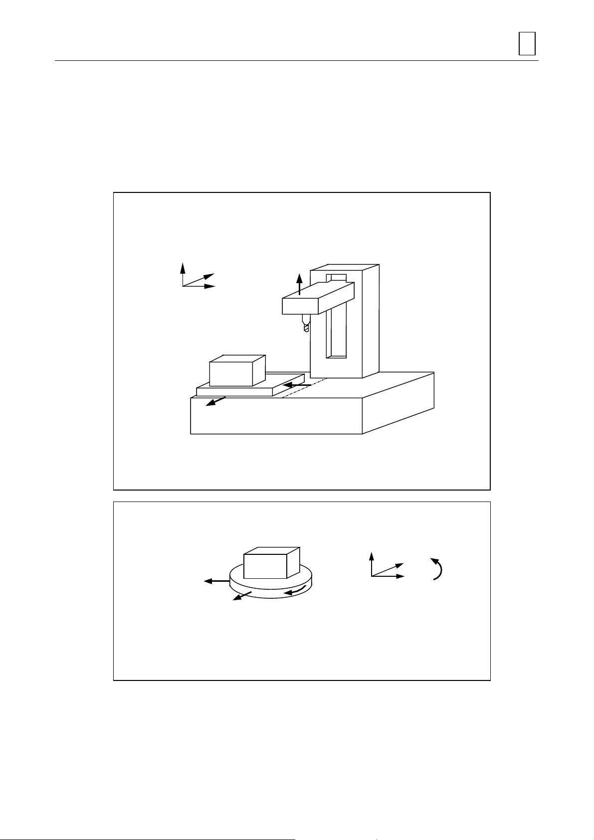
Under standard specifications, there are three-dimensional controlled axes. With an added
feature and a special option, the machine can control up to a maximum of six axes, including the
three fundamental axes. The direction of machining can be designated using a predetermined
coordinate word consisting of an alphabetic character.
For X-Y table
CONTROLLED AXES 1
+Z
+Y
+X
Program coordinates
Workpiece
X-Y table
+Y
For X-Y table and turntable
+Z
Table moving directions
+X
Bed
MEP001
+X
Table moving directions
+Y
Workpiece
Workpiece
+C
Table turning
direction
1-1
+Z
+Y
+X
Program coordinates
+C
MEP002
Page 20

1 CONTROLLED AXES
- NOTE -
1-2
E
Page 21
2 UNITS OF PROGRAM DATA INPUT
2-1 Units of Program Data Input
The movements on coordinate axes are to be commanded in the MDI mode or machining
program. The movement data are expressed in millimeters, inches or degrees.
2-2 Units of Data Setting
Various data commonly used for control axes, such as offsetting data, must be set for the
machine to perform an operation as desired.
The units of data setting and those of program data input are listed below.
UNITS OF PROGRAM DATA INPUT 2
Units of program data input 0.0001 mm 0.00001 in. 0.0001 deg
Units of data setting 0.0001 mm 0.00001 in. 0.0001 deg
Note 1: Inch/metric selection can be freely made using either bit 4 of parameter F91 (“0” for
metric, “1” for inches; validated through power-off and -on) or G-code command s (G20,
G21).
Selection using the G-code commands is valid only for program data input.
Variables and offsetting data (such as tool offsetting data) should therefore be set
beforehand using the appropriate unit (inch or metric) for the particular machining
requirements.
Note 2: Metric data and inch data cannot be used at the same time.
2-3 Ten-Fold Program Data
Using a predetermined parameter, machining program data can be processed as set in units of
one micron. There may be cases that a machining program which has been set in units of one
micron is to be used with a numerical control unit based on 0.1 micron increment s. In such cases,
use of this parameter allows the machine to perform the required machining operations without
rewriting the program.
Use bit 0 of user parameter F91 for this purpose.
All types of coordinate data (axis movement data) not provided with the decimal point will be
multiplied by a factor of 10. This does not apply, indeed, to preset tool-offsetting data designated
with addresses H and D.
Linear axis
Metric system Inch system
Rotational axis
Linear axis
Rotational axis
Program
command
X1 (Y1 / Z1)
B1
Moving distance when program commands are executed
NC (A) for which the
program was prepared
1 micron 0.1 micron 1 micron Applicable
0.001° 0.0001° 0.001° Applicable
Bit 0 of F91 = 0 Bit 0 of F91 = 1
MAZATROL (B)Controlled axis
2-1
Program
applicability
(A) → (B)
Page 22

2 UNITS OF PROGRAM DATA INPUT
- NOTE -
2-2
E
Page 23

3 DATA FORMATS
3-1 Tape Codes
This numerical control unit (in the remainder of this manual, referred to as the NC unit) uses
command information that consists of letters of the alphabet (A, B, C .... Z), numerics (0, 1, 2 ....
9), and signs (+, –, /, and so on). These alphanumerics and signs are referred to collectively as
characters. On paper tape, these characters are represented as a combination of a maximum of
eight punched holes.
Such a representation is referred to as a code.
The NC unit uses either the EIA codes (RS-244-A) or the ISO codes (R-840).
Note 1: Codes not included in the tape codes shown in Fig. 3-1 will result in an error when they
are read.
Note 2: Of all codes specified as the ISO codes but not specified as the EIA codes, only the
following codes can be designated using the data I/O (Tape) parameters TAP9 to
TAP14:
[ Bracket Open
] Bracket Close
# Sharp
∗ Asterisk
= Equal sign
:Colon
However, you cannot designate codes that overlap existing ones or that result in parity
error.
DATA FORMATS 3
Note 3: EIA/ISO code identification is made automatically according to the first EOB/LF code
appearing after the NC unit has been reset. (EOB: End Of Block, LF: Line Feed)
1. Significant information area (LABEL SKIP function)
During tape-based automatic operation, data storage into the memory, or data searching, the NC
unit will ignore the entire information up to the first EOB code (;) in the tape when the unit is
turned on or reset. That is, significant information in a tape refers to the information contained in
the interval from the time a character or numeric code appears, following the first EOB code (;)
after the NC unit has been reset, until a reset command is given.
2. Control Out, Control In
The entire information in the area from Control Out “(” to Control In “)” will be ignored in regard to
machine control, while they will surely be displayed on the data display unit. Thus, this area can
be used to contain information, such as the name and number of the command tape, that is not
directly related to control.
During tape storage, however, the information in this area will also be stored. The NC unit will
enter the Control In status when power is turned on.
3-1
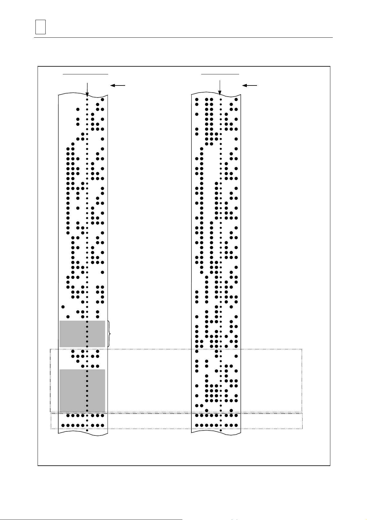
Page 24
3 DATA FORMATS
Example of EIA Code
Control InControl Out
CON
E
U
P R 1 10
O
L
B
Name of tape is printed out
CON
E
1 1 1 1
U
O
L
B
Name of tape is punched in captital letters.
N
D
E
L
D
U
E
L
L
N
R R R O
U
L
R
N
U
.ONMARGO
L
N
UL1
/R
C
E
O
I
B
D
N
N
N
1
1 1
E
L
2DE
U
L
L
E
U
U
O
L
LCI
B
MEP003
Example of ISO Code
E
C
C
OBG0 X–8500 0 640 C U T T E R
R
R
Operator information is printed out.
Control Out
0 0 0
0 0 0G0 X 500 0 40 C U T T E R
YR
(
The information at this portion is ignored
and nothing is executed.
S
S
E T U R N )–
E T U R NR
P
P
Control In
E
O
B
3. EOR code (%)
In general, the EOR (End Of Record) code is punched at both ends of a tape and has the
following functions:
- To stop rewinding (only when a rewinding device is provided)
- To start rewinding during tape data search (only when a rewinding device is provided)
- To terminate the storage of tape data.
MEP004
3-2
Page 25

DATA FORMATS 3
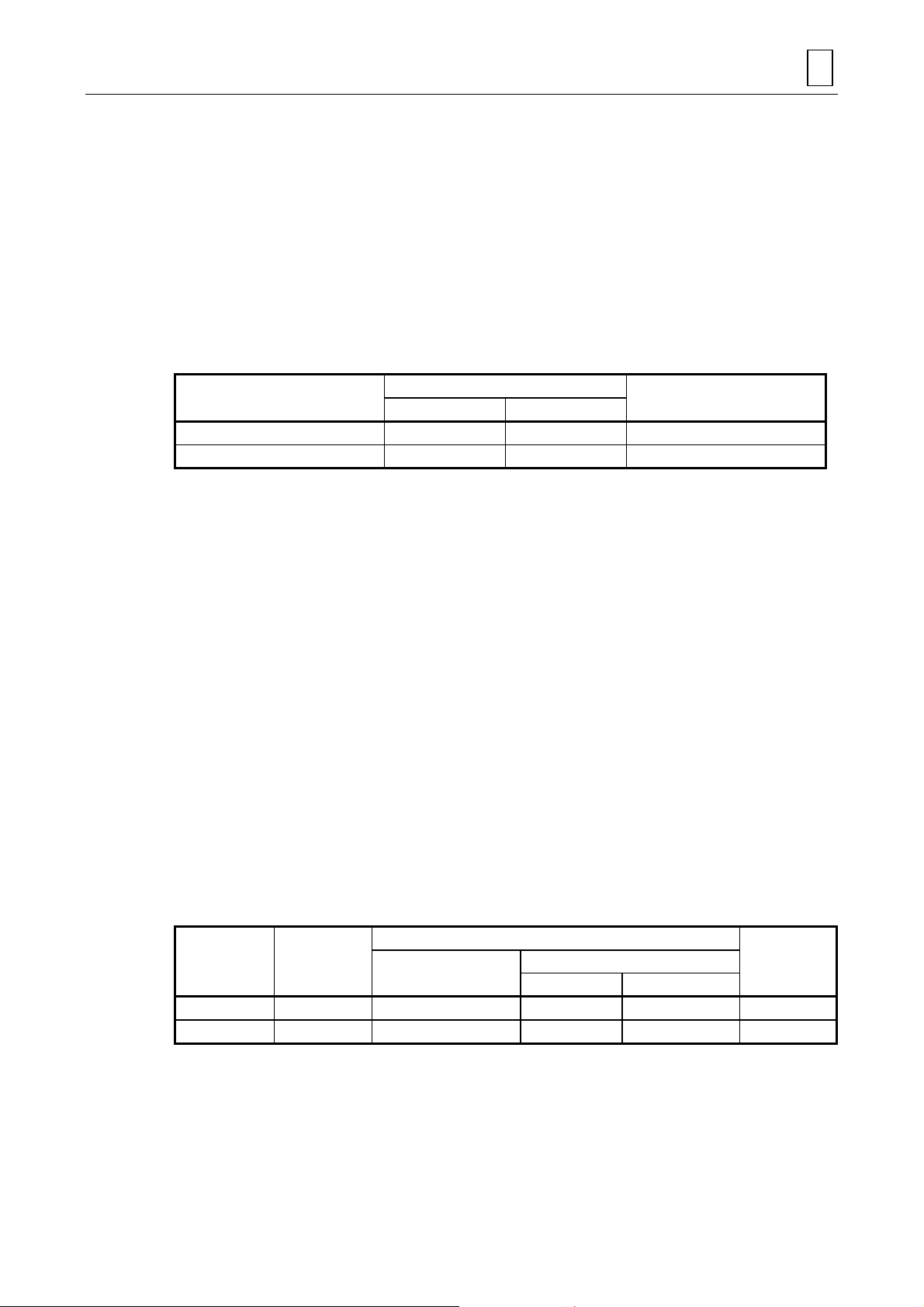
4. Tape creation method for tape operation (Only when a rewinding device is used)
;
10 cm
2m First block Last block 2m
!!!!!!!!!
!!!!!!!!!
; ;
!!!!!!!!!
;
10 cm %%
TEP005
The two meters of dummy at both ends and the EOR (%) at the head are not required when a
rewinding device is not used.
3-3
Page 26
3 DATA FORMATS
A
A
A
A
EIA/ISO identification is made automatically by detecting whether EOB or LF initially appears
after the NC unit has been reset.
EIA code (RS-244-A)
Feed holes
87654 321
Channel number
1
2
3
4
5
6
7
8
9
0
B
C
D
E
F
G
H
I
J
K
L
M
N
O
P
Q
R
S
T
U
V
W
X
Y
Z
+
–
.
,
/
EOR (End of Record)
EOB (End of Block) or CR
CO (2+4+5)
CI (2+4+7)
Definable in parameters
BS (Back Space)
TAB
SP (Space)
&
DEL (Delete)
S (All Space=Feed)*
M (All Mark=EOB+DEL)*
ISO code (R-840)
Feed holes
87654 321
Channel number
1
2
3
4
5
6
7
8
9
0
B
C
D
E
F
G
H
I
J
K
L
M
N
O
P
Q
R
S
T
U
V
W
X
Y
Z
+
–
.
,
/
%
LF (Line Feed) or NL
( (Control Out)
) (Control In)
:
#
?
=
[
]
BS (Back Space)
HT (Horizontal Tab)
SP (Space)
&
CR (Carriage Return)
$
' (Apostrophe)
;
<
>
?
@
"
DEL (Delete)
NULL
DEL (Delete)
[1]
[2]
* The codes asterisked above are not EIA codes,
but may be used for the convenience’s sake.
Fig. 3-1 Tape codes
LF or NL acts as EOB and %
acts as EOR.
MEP006
3-4
Page 27
Codes in section [1] will only be stored as tape data when they are present in a comment section,
A
and ignored elsewhere in the significant information area.
Codes in section [2] are non-operative and will always be ignored (but undergo the parity-V
check).
A dotted area indicates that the EIA Standard provides no corresponding codes.
3-2 Program Formats
A format predetermined for assigning control information to the NC unit is referred to as a
program format. The program format used for our NC unit is word address format.
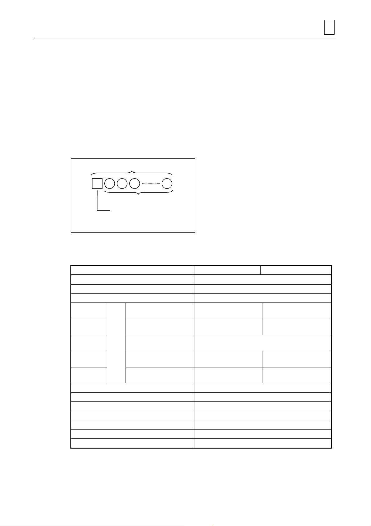
1. Words and addresses
A word is a set of characters arranged as shown below, and information is pro ce ssed in words.
DATA FORMATS 3
Word
Numeral
lphabet (address)
Word configuration
The alphabetic character at the beginning of a word is referred to as an address, which defines
the meaning of its succeeding numeric information.
Table 3-1 Type and format of words
Item Metric command Inch command
Program No. O8
Sequence No. N5
Preparatory function
Moving axis
Auxiliary axis
Dwell
Feed
Fixed cycle
Tool offset
Miscellaneous function M3 × 4
Spindle function S5
Tool function
No. 2 miscellaneous function B8, A8 or C8
Subprogram
Variables number #5
Input
unit
0.0001 mm (deg.),
0.00001 in.
0.0001 mm (deg.),
0.00001 in.
0.001 mm (rev),
0.0001 in.
0.0001 mm (deg.),
0.00001 in.
0.0001 mm (deg.),
0.00001 in.
X+54 Y+54 Z+54 α+54 X+45 Y+45 Z+45 α+45
I+54 J+54 K+54 I+45 J+45 K+45
F54 (per minute)
F33 (per revolution)
R+54 Q54 P8 L4 R+45 Q45 P8 L4
G3 or G21
X54 P8 U54
F45 (per minute)
F24 (per revolution)
H3 or D3
T4 or T8
P8 H5 L4
3-5
Page 28

3 DATA FORMATS
1. Code O8 here indicates that program number can be set as an unsigned integer of eight
digits following O, and for X+54, “+” indicates that the value can be signed (negative) and
the two-digit number (54) indicates that the decimal point can be used and that five digits
before and four after the decimal point are effective (5 + 4 = 9 digits are effective for a
designation without decimal point).
2. The alpha sign (
rotational axis.
3. The number of digits in the words is checked by the maximum number of digits in the
addresses.
4. When data with decimal point is used for address for which decimal input is not available,
decimal figures will be ignored.
5. If the number of integral digits exceeds the specified format, an alarm will result.
6. If the number of decimal digits exceed the specified format, the excess will be rounded.
2. Blocks
A block, unit of instruction, contains a number of words which constitute information necessary
for the NC machine to perform an operation. The end of each block must be indicated by an EOB
(End Of Block) code.
3. Programs
A number of blocks form one program.
4. Program end
M02, M30, M99, M998, M999 or % is used as program end code.
α) denotes additional axis address. +44 will be used when α is specified for
3-3 Tape Data Storage Format
As with tape operation, tape data to be stored into the memory can be either of ISO or EIA code.
The first EOB code read in after resetting is used by the NC unit for automatic identification of the
code system ISO or EIA.
The area of tape data to be stored into the memeory is, if the NC unit has been reset, from the
character immediately succeeding the first EOB code the EOR code, and in all other cases, from
the current tape position to the EOR code. Usually, therefore, start tape data storage operation
after resetting the NC unit.
3-4 Optional Block Skip
1. Function and purpose
Optional block skip is a function that selectively ignores that specific block within a machining
program which begins with the slash code “/”.
Any block beginning with “/” will be ignored if the [BLOCK SKIP] menu function is set to ON, or
will be executed if the menu function is set to OFF.
For example, if all blocks are to be executed for a type of parts but specific blocks are not to be
executed for another type, then different parts can be machined using one and the same
program that contains the “/” code at the beginning of the specific blocks.
3-6
Page 29

2. Operating notes
1. Blocks that have already been read into the pre-read buffer cannot be skipped.
2. This function is valid even during sequence number search.
3. During tape data storage (input) or output, all blocks, including those having a “/” code, are
in- or outputted, irrespective of the status of the [BLOCK SKIP] menu function.
3-5 Program Number, Sequence Number and Block Number: O, N
Program numbers, sequence numbers, and block numbers are used to monitor the execution
status of a machining program or to call a machining program or a specific process within a
machining program.
Program numbers are assigned to command blocks as required. A program number must be set
using the letter O (address) and a numeric of a maximum of eight digits that follow O.
Sequence numbers identify command blocks forming a machining program. A sequence number
must be set using the letter N (address) and a numeric of a maximum of five digits that follow N.
Block numbers are counted automatically within the NC unit, and reset to 0 each time a program
number or a sequence number is read. These numbers will be counted up by one if the block to
be read does not have an assigned program number or sequence number.
All blocks of a machining program, therefore, can be uniquely defined by combining program
number, sequence number, and block number as shown in the table below.
DATA FORMATS 3
NC input machining program
O1234 (DEMO. PROG)
G92X0Y0
G90G51X–150. P0.75
N100G00X–50. Y–25.
N110G01X250. F300
Y–225.
X–50.
Y–25.
N120G51Y–125. P0.5
N130G00X–100. Y–75.
N140G01X–200.
Y–175.
X–100.
Y–75.
N150G00G50X0Y0
N160M02
%
NC monitor display
Program No. Sequence No. Block No.
1234 0 0
1234 0 1
1234 0 2
1234 100 0
1234 110 0
1234 110 1
1234 110 2
1234 110 3
1234 120 0
1234 130 0
1234 140 0
1234 140 1
1234 140 2
1234 140 3
1234 150 0
1234 160 0
3-7
Page 30

3 DATA FORMATS
3-6 Parity-H/V
One method of checking if the tape is correctly created is by parity checks. Parity checks are
performed to check a tape for errors in punched codes, that is, for punching errors. There are two
types of parity checks: parity-H and parity-V.
1. Parity-H check
Parity-H checks are intended to check the quantity of punched holes which form one character,
and performed during tape operation, tape loading, and sequence-number searching.
A parity-H error occurs in the following cases:
- ISO Codes
If a code with an odd number of punched holes is present in the significant information area.
- EIA Codes
If a code with an even number of punched holes is present in the significant information area or
if non-punched holes (sprockets only) are present after a significant code in one block.
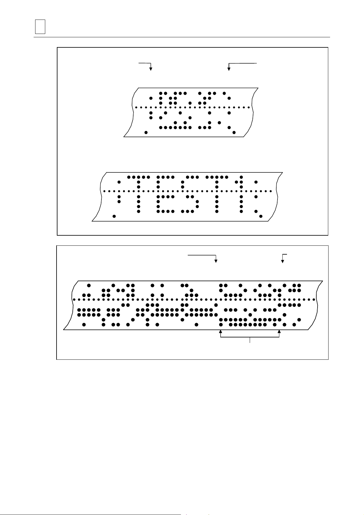
Example 1: Parity-H error (for EIA codes)
This character leads to a Parity-H error.
One block
This non-punched character will result in a Parity-H
error.
These non-punched characters will
not result in a Parity-H error.
If a parity-H error occurs, the tape will stop at the position next to the error code.
MEP007
3-8
Page 31

DATA FORMATS 3
2. Parity-V check
Parity-V checks will be performed during tape operation, tape loading, or sequence-number
searching, if parity-V check item on the PARAMETER display is set to ON. Parity-V during
memory operation, however, will not be checked.
A parity-V error occurs in the following case:
If an odd number of codes are present in the significant information area from the first significant
code in the vertical direction to the EOB code (;), that is, if an odd number of characters are
present in one block.
In the event of a parity-V error, the tape stops at a code next to the EOB (;).
Example 2: An example of parity-V error
1234567
This block leads to a Parity-V error.
MEP009
Note 1: During a parity-V check, some types of code are not counted as characters. See Fig.
3-1, “Tape codes” for further details.
Note 2: Space codes in the area from the first EOB code to the first address code or slash code
“/” are not subjected to counting for parity-V check.
3-9
Page 32

3 DATA FORMATS
3-7 List of G-Codes
G functions are described in the list below.
Positioning
Linear interpolation
Circular interpolation (CW) G02 01
Circular interpolation (CCW) G03 01
Spiral interpolation (CW) G02.1 01
Spiral interpolation (CCW) G03.1 01
Dwell G04 00
High-speed machining mode G05 00
Fine spline interpolation G06.1 01
NURBS interpolation G06.2 01
Virtual-axis interpolation G07 00
Cylindrical interpolation G07.1 00
Exact-stop check G09 00
Data setting mode ON G10 00
Command address OFF G10.1 00
Data setting mode OFF G11 00
X-Y plane selection
Z-X plane selection
Y-Z plane selection
Inch command
Metric command
Pre-move stroke check ON G22 04
Pre-move stroke check OFF ▲G23 04
Reference point check G27 00
Reference point return G28 00
Return from reference point G29 00
Return to 2nd, 3rd and 4th reference points G30 00
Skip function G31 00
Multi-step skip 1 G31.1 00
Multi-step skip 2 G31.2 00
Multi-step skip 3 G31.3 00
Thread cutting (straight, taper) G33 01
Variable lead thread cutting G34 01
Hole machining pattern cycle (on a circle) G34.1 00
Hole machining pattern cycle (on a line) G35 00
Hole machining pattern cycle (on an arc) G36 00
Hole machining pattern cycle (on a grid) G37.1 00
Automatic tool length measurement G37 00
Vector selection for tool radius compensation G38 00
Corner arc for tool radius compensation G39 00
Tool radius compensation OFF ▲G40 07
Tool radius compensation (left) G41 07
3-D tool radius compensation (left) G41.2 07
Tool radius compensation (right) G42 07
3-D tool radius compensation (right) G42.2 07
Tool length offset (+) G43 08
Function G-code Group
■G00
■G01
■G17
■G18
■G19
■G20
■G21
01
01
02
02
02
06
06
3-10
Page 33

Function G-code Group
Tool tip point control (Type 1) ON G43.4 08
Tool tip point control (Type 2) ON G43.5 08
Tool length offset (–) G44 08
Tool position offset, extension G45 00
Tool position offset, reduction G46 00
Tool position offset, double extension G47 00
Tool position offset, double reduction G48 00
Tool position offset OFF ▲G49 08
Scaling OFF ▲G50 11
Scaling ON G51 11
Mirror image OFF ▲G50.1 19
Mirror image ON G51.1 19
Local coordinate system setting G52 00
Machine coordinate system selection G53 00
Selection of workpiece coordinate system 1 ▲G54 12
Selection of workpiece coordinate system 2 G55 12
Selection of workpiece coordinate system 3 G56 12
Selection of workpiece coordinate system 4 G57 12
Selection of workpiece coordinate system 5 G58 12
Selection of workpiece coordinate system 6 G59 12
Additional workpiece coordinate systems G54.1 12
Selection of fixture offset G54.2 23
One-way positioning G60 00
Exact stop mode G61 13
High-accuracy mode (Geometry compensation) G61.1 13
Automatic corner override G62 13
Tapping mode G63 13
Cutting mode ▲G64 13
User macro single call G65 00
User macro modal call A G66 14
User macro modal call B G66.1 14
User macro modal call OFF ▲G67 14
Programmed coordinate rotation ON G68 16
Programmed coordinate rotation OFF G69 16
3-D coordinate conversion ON G68 16
3-D coordinate conversion OFF ▲G69 16
Fixed cycle (Chamfering cutter 1, CW) G71.1 09
Fixed cycle (Chamfering cutter 2, CCW) G72.1 09
Fixed cycle (High-speed deep-hole drilling) G73 09
Fixed cycle (Reverse tapping) G74 09
Fixed cycle (Boring 1) G75 09
Fixed cycle (Boring 2) G76 09
Fixed cycle (Back spot facing) G77 09
Fixed cycle (Boring 3) G78 09
Fixed cycle (Boring 4) G79 09
Fixed cycle OFF ▲G80 09
Fixed cycle (Spot drilling) G81 09
Fixed cycle (Drilling) G82 09
Fixed cycle (Deep-hole drilling) G83 09
DATA FORMATS 3
3-11
Page 34

3 DATA FORMATS
Fixed cycle (Tapping) G84 09
Fixed cycle (Synchronous tapping) G84.2 09
Fixed cycle (Synchronous reverse tapping) G84.3 09
Fixed cycle (Reaming) G85 09
Fixed cycle (Boring 5) G86 09
Fixed cycle (Back boring) G87 09
Fixed cycle (Boring 6) G88 09
Fixed cycle (Boring 7) G89 09
Absolute data input
Incremental data input
Coordinate system setting/Spindle clamp speed setting G92 00
Workpiece coordinate system rotation G92.5 00
Inverse time feed G93 05
Feed per minute (asynchronous)
Feed per revolution (synchronous)
Initial point level return in fixed cycles ▲G98 10
R-point level return in fixed cycles G99 10
Measurement macro, workpiece/coordinate measurement G136
Compensation macro G137
Function G-code Group
■G90
■G91
■G94
■G95
03
03
05
05
Notes:
1. The codes marked with ▲ are selected in each group when the power is turned ON or
executing reset for initializing modal.
2. The codes marked with " are able to be selected by a parameter as an initial modal which is
to become valid when the power is turned ON or executing reset for initializing modal.
Changeover of inch/metric system, however, can be made valid only by turning the power
ON.
3. G-codes of group 00 are those which are not modal, and they are valid only for commanded
blocks.
4. If a G-code not given in the G-code list is commanded, an alarm is displayed. And if a Gcode without corresponding option is commanded, an alarm is displayed (808 MIS-SET G
CODE).
5. If G-codes belong to different groups each other, any G-code can be commanded in the
same block. The G-codes are then processed in order of increasing group number. If two or
more G-codes belonging to the same group are commanded in the same block, a G-code
commanded last is valid.
3-12
E
Page 35

4 BUFFER REGISTERS
4-1 Input Buffer
1. Overview
During tape operation or RS-232C operation, when the preread buffer becomes empty, the
contents of the input buffer will be immediately shifted into the pre-read buffer and, following this,
if the memory capacity of the input buffer diminuishes to 248 × 4 characters or less, next data (up
to 248 characters) will be preread from the tape and then stored into the input buffer.
The input buffer makes block-to-block connections smooth by eliminating any operational delays
due to the tape-reading time of the tape reader.
These favorable results of prereading, however, will be obtained only if the execution time of the
block is longer than the tape-reading time of the next block.
BUFFER REGISTERS 4
Tape
Keyboard
Input buffer
Memory
Mode
selection
Preread
buffer 5
Buffer 4
Buffer 3
Buffer 2
Buffer 1
Note:
One block of data is stored in one buffer.
2. Detailed description
- The memory capacity of the input buffer is 248 × 5 characters (including the EOB code).
- The contents of the input buffer register are updated in 248-character units.
Arithmetic
operation
process
TEP010
- Only the significant codes in the significant information area are read into the buffer.
- Codes, including “(” and “)”, that exist between Control Out and Control In, are read into the
input buffer. Even if optional block skip is valid, codes from / to EOB will also be read into the
input buffer.
- The contents of the buffer are cleared by a reset command.
4-1
Page 36

4 BUFFER REGISTERS
4-2 Preread Buffer
1. Overview
During automatic operation, one block of data is usually preread to ensure smooth analysis of
the program. During tool radius compensation, however, maximal five blocks of data are prere ad
to calculate crossing point or to check the interference.
In the high-speed machining mode (G05P2), moreover, up to 8 blocks of data are preread, and in
the mode of high-speed smoothing control up to 24 blocks of data are stored with the currently
executed block in the middle (i. e. 12 blocks being preread).
2. Detailed description
- One block of data is stored into the prepared buffer.
- Only the significant codes in the significant information area are read into the pre-read buffer.
- Codes existing between Control Out and Control In are not read into the pre-read buffer. If
optional block skip is valid, codes from / to EOB will not also be read into the pre-read buffer.
- The contents of the buffer are cleared by a reset command.
- If the single block operation mode is selected during continuous operation, processing will stop
after pre-reading the next block data.
4-2
E
Page 37

5 POSITION PROGRAMMING
5-1 Dimensional Data Input Method
5-1-1 Absolute/Incremental data input: G90/G91
1. Function and purpose
Setting of G90 or G91 allows succeeding dimensional data to be processed as absolute data or
incremental data.
Setting of arc radius (with address R) or arc center position (with addresses I, J, K) for circular
interpolation, however, must always refer to incremental data input, irrespective of preceding
G90 command.
2. Programming format
POSITION PROGRAMMING 5
G90 (or G91) Xx
Yy1 Zz1 αα1 (α : Additional axis)
1
where G90: Absolute data input
G91: Incremental data input
3. Detailed description
1. In the absolute data mode, axis movement will be performed to the program-designated
position within the workpiece coordinate system, irrespective of the current position.
N1 G90G00X0 Y0
In the incremental data mode, axis movement will be performed through the programdesignated distance as relative data with respect to the current position.
N2 G91G01X200. Y50. F100
N2 G90G01X200. Y50. F100
Y
200.
Tool
100.
N1
N2
100. 200. 300.
W
X
MEP011
Commands for a movement from the origin of the workpiece coordinate system are given
with the same
values, irrespective of whether the absolute data mode or the incremental
data mode is used.
5-1
Page 38

5 POSITION PROGRAMMING
2. The last G90 or G91 command works as a modal one for the following blocks.
(G90) N3 X100. Y100.
This block will perform a movement to the position of X = 100 and Y = 100 in the workpiece
coordinate system.
(G91) N3 X-100. Y50.
This block will perform a movement of –100 on the X-axis and +50 on the Y-axis, and thus
result in a movement to the position of X = 100 and Y = 100.
Y
200.
100.
100. 200. 300.
W
N3
X
MEP012
3. Multiple G90 or G91 commands can be set in one block, and thus only a specific address
can be set as absolute data or incremental data.
N4 G90X300. G91Y100.
In this example, dimensional data X300 preceded by G90 will be processed as an absolute
data input, and Y100 preceded by G91 as an incremental data input. Therefore, this block
will result in a movement to the position of X = 300 and Y = 200 (100 + 100) in the workpiece
coordinate system.
Y
200.
N4
100.
X
W
100. 200.
300.
MEP013
Moreover, G91 (incremental data input mode) will work for the succeeding blocks.
4. Either the absolute data mode or the incremental data mode can be freely selected as initial
mode by setting the bit 2 of user parameter F93.
5. Even in the MDI (Manual Data Input) mode, G90 and G91 will also be handled as modal
commands.
5-2
Page 39

5-2 Inch/Metric Selection: G20/G21
1. Function and purpose
Inch command/metric command selection is possible with G-code commands.
2. Programming format
G20: Inch command selection
G21: Metric command selection
3. Detailed description
1. Changeover between G20 and G21 is effective only for linear axes; it is meaningless for
rotational axes.
Example: Preset unit of data input and G20/G21 (for decimal-point input type Ι)
POSITION PROGRAMMING 5
Axis Example
X
Y
Z
B
X100
Y100
Z100
B100
Initial Inch (parameter) OFF Initial Inch (parameter) ON
G21 G20 G21 G20
0.0100 mm 0.0254 mm 0.00039 inches 0.00100 inches
0.0100 mm 0.0254 mm 0.00039 inches 0.00100 inches
0.0100 mm 0.0254 mm 0.00039 inches 0.00100 inches
0.0100 deg 0.0100 deg 0.0100 deg 0.0100 deg
2. To perform G20/G21 changeover in a program, you must first convert variables, parameters,
and offsetting data (such as tool length/tool position/tool diameter offsetting data) according
to the unit of data input for the desired system (inch or metric) a nd then set all these types of
data either on each data setting display or using the programmed parameter input function.
Example: If Initial inch selection is OFF and offsetting data is 0.05 mm, the offsetting data
must be converted to 0.002 (0.05 ÷ 25.4 ≈ 0.002) before changing the G21
mode over to the G20 mode.
3. In principle, G20/G21 selection should be done before machining. If you want this
changeover to be performed in the middle of the program, temporarily stop the program by
an M00 command after G20 or G21 and convert the offsetting data as required.
Example: G21 G92 Xx
Yy1 Zz
1
1
MM
MM
MM
G20 G92 Xx
Yy2 Zz
2
2
M00 → Convert offsetting data here.
M
F10 → Set an F (Feed rate) command anew.
Note: Do not fail to give an F command appropriate to the new unit system after
changeover between G20 and G21. Otherwise, axis movements would be
performed using the last F value before the changeover, without any conversion,
on the basis of the new unit system.
4. Whether G20 or G21 is to be selected upon switching-on can be specified by the bit 4 of
user parameter F91 (Initial Inch parameter).
5-3
Page 40

5 POSITION PROGRAMMING
5-3 Decimal Point Input
1. Function and purpose
The decimal point can be used to determin the units digit (mm or inch) of dimensional data or
feed rate.
2. Programming format
!!!!!.!!!! Metric system
!!!!.!!!!! Inch system
3. Detailed description
1. Decimal-point commands are valid only for the distance, angle, time, speed, and scaling
factor (only after G51) that have been set in the machining program.
2. As listed in the table below, the meaning of command data without the decimal point differs
between decimal-point input types Ι and ΙΙ according to the type of command unit system.
Command Command unit × 10 Type Ι Type ΙΙ
X1
OFF 0.0001 (mm, inches, deg) 1.0000 (mm, inches, deg)
ON 0.0010 (mm, inches, deg) 1.0000 (mm, inches, deg)
3. Decimal-point commands are only valid for addresses X, Y, Z, U, V, W, A, B, C, I, J, K, E, F,
P, Q and R, where address P only refers to a scaling factor.
4. The number of effective digits for each type of decimal-point command is as follows:
Move command
(Linear)
Integral part Decimal part Integral part Decimal part Integral part Decimal part Integral part Decimal part
mm 0. - 99999. .0000 - .9999 0. - 99999. .0000 - .9999 0. - 200000. .0000 - .9999 0. - 99999. .000 - .999
inch 0. - 9999.
.00000 .99999
Move command
(Rotational)
0. - 99999.
(359.)
Feed rate Dwell
.0000 - .9999 0. - 20000.
.00000 .99999
0. - 99999. .000 - .999
5. Decimal-point commands are also valid for definition of variables data used in subprograms.
6. For data which can be, but is not specified with the decimal point, either the minimum
program data input unit or mm (or in.) unit can be selected using bit 5 of parameter F91.
7. A decimal-point command issued for an address which does not accept the decimal point
will be processed as data that consists of an integral part only. That is, all decimal digits will
be ignored. Addresses that do not accept the decimal point are D, H, L, M, N, O, S and T. All
types of variables command data are handled as the data having the decimal point.
5-4
Page 41

4. Sample programs
A. Sample programs for addresses accepting the decimal point
POSITION PROGRAMMING 5
Command category
Program example
G0X123.45
(With the decimal point always given
as the millimeter point)
G0X12345
#111=123 #112=5.55
X#111 Y#112
#113=#111+#112 (ADD)
#114=#111–#112 (SUBTRACT)
#115=#111#112 (MULTIPLY)
#116=#111/#112
#117=#112/#111 (DIVIDE)
For 1 = 1 µ For 1 = 0.1 µ 1 = 1 mm
X123.450 mm X123.450 mm X123.450 mm
X12.345 mm* X1.2345 mm** X12345.000 mm***
X123.000 mm
Y5.550 mm
#113 = 128.550
#114 = 117.450
#115 = 682.650
#116 = 22.162
#117 = 0.045
* The least significant digit is given in 1 micron.
** The least significant digit is given in 0.1 micron.
*** The least significant digit is given in 1 mm.
5-5
Page 42

5 POSITION PROGRAMMING
B. Validity of decimal point for each address
Decimal
Address
A
B
C
D Invalid
E Valid Valid
F Valid Feed rate Valid
G Valid Preparatory function code
H
I
J
K
L Invalid
M Invalid Miscellaneous function code
point
command
Valid Coordinate position data Invalid Dwell time
Invalid
Valid Linear angle data Invalid Number of helical pitches
Valid Coordinate position data Invalid Offset amount (in G10)
Invalid
Valid Coordinate position data Valid
Invalid
Valid Corner chamfering amount
Invalid
Invalid
Valid Coordinate of arc center U Valid Coordinate position data
Valid
Valid Coordinate of arc center W Valid Coordinate position data
Valid
Valid Coordinate of arc center
Valid
Valid Knot for NURBS curve Z Valid Coordinate position data
Rotary table
Miscellaneous function code
Rotary table
Miscellaneous function code
Rotary table
Miscellaneous function code
Offset number (tool position,
tool length and tool diameter)
Offset number (tool postion,
tool length and tool diameter)
Intra-subprogram sequence
number
Vector component for
tool diameter offset
Vector component for
tool diameter offset
Vector component for
tool diamater offset
Fixed cycle/subprogram
repetition
Application Remarks Address
P
Q
R
S Invalid Spindle function code
T Invalid Tool function code
V Valid Coordinate position data
X
Y Valid Coordinate position data
Decimal
point
command
Valid Subprogram call number
Valid Scaling factor
Invalid Rank for NURBS curve
Cutting depth for
deep-hole drilling cycle
Valid Shift amount for back boring
Valid Shift amount for fine boring
Valid R point in fixed cycle
Radius of an arc with R
selected
Radius of an arc for corner
rounding
Valid Offset amount (in G10)
Valid Weight for NURBS curve
Valid Coordinate position data
Valid Dwell time
Application Remarks
N Invalid Sequence number
O Invalid Program number
Note: The decimal point is valid in all the arguments for a user macroprogram.
5-6
E
Page 43

6 INTERPOLATION FUNCTIONS
6-1 Positioning (Rapid Feed): G00
1. Function and purpose
Positioning command G00 involves use of a coordinate word. This command positions a tool by
moving it linearly to the ending point specified by a coordinate word.
2. Programming format
INTERPOLATION FUNCTIONS 6
G00 Xx Yy Zz α
The command addresses are valid for all additional axis.
input is used according to the status of G90/G91 existing at the particular time.
3. Detailed description
1. Once this command has been given, the G00 mode will be retained until any other G-code
command that overrides this mode, that is, either G01, G02, G03, or G32 of command
group 01 is given. Thus, a coordinate word will only need be given if the next command is
also G00. This function is referred to as the modal function of the command.
2. In the G00 mode, acceleration/deceleration always takes place at the starting/ending point
of a block and the program proceeds to the next block after confirming that the pulse
command in the present block is 0 and the tracking error of the acceleration/deceleration
cycle is 0. The width of in-position can be changed using a parameter (S13).
3. The G-code functions (G71.1 to G89) of command group 09 are canceled by the G00
command (G80).
4. The tool path can be made either linear or nonlinear using a parameter (F91 bit 6) but the
positioning time remains unchanged.
- Linear path
As with linear interpolation (G01), the tool speed is limited according to the rapid feed rate
of each axis.
α; (α: Additional axis)
The absolute or the incremental data
- Nonlinear path
The tool is positioned according to the separate rapid feed rate of each axis.
5. When no number following G address, this is treated as G00.
6-1
Page 44

6 INTERPOLATION FUNCTIONS
–
–
4. Sample programs
Z
Unit: mm
(Tool)
Starting point
(+150, –100, +150)
X
+300
100
+150
+150
120
+200
Ending point
(–120, +200, +300)
Y
MEP014
The diagram above is for:
G90 G00 X-120.000 Y200.000 Z300.000; Absolute data command
G91 G00 X-270.000 Y300.000 Z150.000; Incremental data command
5. Remarks
1. If bit 6 of user parameter F91 is 0, the tool will take the shortest path connecting the starting
and ending points. The positioning speed will be calculated automatically to give the
shortest allocation time within the limits of the rapid feed rate of each axis.
For example, if a rapid feed rate of 9600 mm/min is preset for both X- and Y-axes, then the
command
G91 G00 X–300.000 Y200.000
will move the tool as shown in the figure below.
bit 6 = 0
F91
Ending point
300
fx
X-axis effective feedrate:
9600 mm/min
Y-axis effective feedrate:
6400 mm/min
200
fy
Starting point
Y
X
Unit: mm
MEP015-1
6-2
Page 45

INTERPOLATION FUNCTIONS 6
2. If bit 6 of user parameter F91 is 1, the tool will move from the starting point to the ending
point according to the rapid feed rate of each axis.
For example, if a rapid feed rate of 9600 mm/min is preset for both X- and Y-axes, then the
command
G91 G00 X–300.000 Y200.000
will move the tool as shown in the figure below.
bit 6 = 1
F91
Ending point
X-axis effective feedrate:
9600 mm/min
300
200
Starting point
fx
Y-axis effective feedrate:
9600 mm/min
Y
fy
X
Unit: mm
MEP015-2
3. The rapid feed rate that you can set for each axis using the G00 command varies from
machine to machine. Refer to the relevant machine specification for further details.
4. Rapid feed (G00) deceleration check
When processing of rapid feed (G00) is completed, the next block will be executed after the
deceleration check time (Td) has passed.
The deceleration check time (Td) is calculated by following expressions depending on the
acceleration/deceleration type.
Linear acceleration/linear deceleration .............................. Td = Ts + a
Exponential acceleration/linear deceleration .....................Td = 2 × Ts + a
Exponential acceleration/exponential deceleration............Td = 2 × Ts + a
(Where Ts is the acceleration time constant, a = 0 to 14 msec)
The time required for the deceleration check during rapid feed is the longest among the
rapid feed deceleration check times of each axis determined by the rapid feed
acceleration/deceleration time constants and by the rapid feed acceleration/deceleration
mode of the axes commanded simultaneously.
6-3
Page 46

6 INTERPOLATION FUNCTIONS
(–)
6-2 One-Way Positioning: G60
1. Function and purpose
Highly accurate positioning free from any backlash error can be performed when the axis
movement is controled by the G60 command so that the final access always takes place in one
determined direction.
2. Programming format
G60 Xx Yy Zz α
α; (α: Additional axis)
3. Detailed description
1. The direction of final access and its creeping distance must be set in parameter I1.
2. After rapid approach to a position away from the ending point by the creeping distance, the
final access is performed in the predetermined direction at a speed corresponding with the
rapid feed.
G60 a
Starting point
Temporary stop
G60 creeping distance
Positioning point
Final access direciton
Ending point
Starting point
G60 –a
3. The positioning pattern described above also applies during machine locking or for a Z-axis
command with the Z-axis cancellation activated.
(+)
MEP018
4. In the dry run mode (G00 mode), the whole positioning is carried out at the dry-running
speed.
5. The creeping to the einding point can be halted with Reset, Emergency stop, Interlock, or
Feed hold, or by setting the rapid feed override to 0 (zero).
The creeping is performed according to the setting of the rapid feed, and the rapid feed
override function is also effective for the creeping.
6. One-way positioning is automatically invalidated for the hole-drilling axis in hole-drilling
fixed-cycle operations.
7. One-way positioning is automatically invalidated for shifting in fine-boring or back-boring
fixed-cycle operations.
8. Usual positioning is performed for an axis not having a parameter-set creeping distance.
9. One-way positioning is always of non-interpolation type.
10. An axis movement command for the same position as the ending point of the preceding
block (movement distance = 0) will cause reciprocation through the creeping distance so
that the final access can be performed in the predetermined direction for an accurate
positioning to the desired point.
6-4
Page 47

6-3 Linear Interpolation: G01
1. Function and purpose
This command moves (interpolates) a tool from the current position to the ending point specified
by a coordinate word, at the feed rate specified with address F. The specified feed rate acts here
as the linear velocity relative to the direction of movement of the tool center.
2. Programming format
INTERPOLATION FUNCTIONS 6
G01 Xx Yy Zz α
where x, y, z, and
α Ff; (α: Additional axis)
α each denote a coordinate. The absolute or the incremental data input is used
according to the status of G90/G91 existing at the particular time.
3. Detailed description
Once this command has been given, the G01 mode will be retained until any other G-code
command that overrides this mode, that is, either G00, G02, G03 or G33 of command group 01
is given. Thus, it is merely required to input coordinate words for linear interpolations in the
succeeding blocks unless the feed rate must be changed.
A programming error will result if no F-code command has been given to the first G01 command.
The feed rates for rotational axes must be set in deg/min. (Example: F300 = 300 deg/min)
The G-code functions (G71.1 to G89) of command group 09 are cancelled by G01 (set to G80).
4. Sample program
The following shows a program for moving the tool at a cutting feed rate of 300 mm/min on the
route of P1 → P2 → P3 → P4 → P1 (where the section from P0 → P1 forms a positioning route for
the tool):
30
P
P
2
3
Y
30
P
1
2020
P
0
P
4
20
G91 G00 X20. Y20. P0 → P
G01 X20. Y30. F300 P1 → P
X30. P2 → P
X–20. Y–30. P3 → P
X–30. P4 → P
6-5
X
Unit: mm
MEP019
1
2
3
4
1
Page 48

6 INTERPOLATION FUNCTIONS
6-4 Circular Interpolation: G02, G03
1. Function and purpose
Commands G02 and G03 feed the tool along an arc.
2. Programming format
G02 (G03)
Xx Yy (Zz) Ii Jj (Kk) Ff ;
Coordinates of the
ending point
Counterclockwise (CCW)
Clockwise (CW)
Coordinates of
the arc center
Feedrate
X : Arc ending point coordinate, X-axis
Y : Arc ending point coordinate, Y-axis
Z : Arc ending point coordinate, Z-axis
I : Arc center, X-axis
J : Arc center, Y-axis
K : Arc center, Z-axis
F : Feed rate
Use addresses X, Y and Z (or their parallel axes) to specify the coordinates of the ending point of
arc, and addresses I, J and K for the coordinates of arc center.
Combined use of absolute and incremental data input is available for setting the coordinates of
the ending point of arc. For the coordinates of the arc center, however, incremental data relative
to the starting point must always be set.
3. Detailed description
1. Once the G02 (or G03) command has been given, this command mode will be retained until
any other G-code command used to override the G02 (or G03) comma nd mode, that is, G00
or G01 of command group 01 is given.
6-6
Page 49

2. The direction of circular movement is determined by G02/G03.
G02: CW (Clockwise)
G03: CCW (Counterclockwise)
Z
G02 G03
G03
G03
G02
G02
INTERPOLATION FUNCTIONS 6
Y
Y
G03
G02
X
G17 (X-Y) plane G18 (Z-X) plane
X
X
G02
G03
Z
G03
G02
Z
G19 (Y -Z ) Plane
Y
MEP020
3. Interpolation of an arc that spans multiple quadrants can be defined with one block.
4. To perform circular interpolation, the following information is required:
- Rotational direction ......................CW (G02) or CCW (G03)
- Arc ending point coordinates .......Given with address X, Y, Z.
- Arc center coordinates.................Given with address I, J, K. (Incremental dimension)
- Feed rate......................................Given with address F.
5. If none of the addresses I, J, K and R is specified, a program error will occur.
6. Addresses I, J and K are used to specify the coordinates of the arc center in the X, Y and Z
directions respectively as seen from the starting point, therefore, care must be taken for
signs.
6-7
Page 50

6 INTERPOLATION FUNCTIONS
4. Sample programs
Example 1: Complete-circle command
Y-axis
Feedrate
F = 500 mm/min
X-axis
Circle ce nter
J = 50 mm
Starting / Ending point
G02 J50.000 F500
Example 2: Three-quarter circle command
Y-axis
+Y
+X
MEP021
+Y
Feedrate
F = 500 mm/min
X-axis
Circle ce nter
J = 50 mm
Starting point
Ending point
(x+50, y+50)
+X
MEP022
G91 G02 X50.000 Y50.000 J50.000 F500
5. Notes on circular interpolation
1. Clockwise (G02) or Counterclockwise (G03) during circular interpolation refers to the
rotational direction in the right-handed coordinate system when seen from the plus side
toward the minus side of the coordinate axis perpendicular to the plane to be interpolated.
2. If the coordinates of the ending point are not set or if the starting and ending points are set
at the same position, designating the center using address I, K or J will result in an arc of
360 degrees (true circle).
6-8
Page 51

INTERPOLATION FUNCTIONS 6
A
3. The following will result if the starting-point radius and the ending-point radius are not the
same.
- If error ∆R is larger than the parameter F19 (tolerance for radial value difference at ending
point), a program error (817 INCORRECT ARC DATA) will occur at the starting point of
the arc.
G02 X80. I50.
larm stop
Center Ending point
Starting
point
Radius at
starting point
Radius at
ending point
R
∆
MEP023
- If error ∆R is equal to or smaller than the parameter data, interpolation will take a spiral
form heading for the programmed ending point of the arc.
G02 X90. I50.
Starting
point
Radius at
starting point
Center Ending point
Spiral
interpolation
Radius at
ending point
R
∆
MEP024
The examples shown above assume that excessively large parameter data is given to
facilitate your understanding.
6-5 Radius Designated Circular Interpolation: G02, G03
1. Function and purpose
Circular interpolation can be performed by designating directly the arc radius R as well as
specifying conventional arc center coordinates (I, J, K).
2. Programming format
G02 (G03) Xx Yy Rr Ff;
where x : X-axis coordinate of the ending point
y : Y-axis coordinate of the ending point
r : Radius of the arc
f : Feed rate
6-9
Page 52

6 INTERPOLATION FUNCTIONS
3. Detailed description
The arc center is present on the mid-perpendicular to the segment which connects the starting
point and the ending point. The crossing point of the mid-perpendicular and that circle of the
designated radius r that has the center set at the starting point gives the center coordinates of
the designated arc.
A semi-circle or smaller will be generated if R is a positive value.
An arc larger than the semi-circle will be generated if R is a negative value.
Path of an arc with a negative-signed R
Ending point
Path of a n arc with a positive R
O1, O2 : Center point
TEP023
Starting point
O
2
O
L
r
1
To use the radius-designated arc interpolation commands, the following requirement must be
met:
L
≤
1
r
2
•
where L denotes the length of the line from the starting point to the ending point.
If radius data and arc center data (I, J, K) are both set in the same block, the circular interpolation
by radius designation will have priority in general.
For complete-circle interpolation (the ending point = the starting point), however, use centerdesignation method with addresses I, J and K, since the radius-specification command in this
case will immediately be completed without any machine operation.
4. Sample programs
- G02 Xx
- G03 Zz
- G02 Xx
Yy1 Rr1 Ff
1
Xx1 Rr1 Ff
1
Yy1 Jj1 Rr1 Ff
1
- G17 G02 Ii
1
1
Ji1 Rr1 Ff
1
X-Y plane, radius-designated arc
Z-X plane, radius-designated arc
X-Y plane, radius-designated arc
1
(If radius data and center data (I, J, K) are set in the same block,
circular interpolation by radius designation will have priority.)
X-Y plane, center-designated arc
1
(Radius-specification is invalid for complete circle)
6-10
Page 53

6-6 Spiral Interpolation: G2.1, G3.1 (Option)
1. Function and purpose
INTERPOLATION FUNCTIONS 6
Commands G2.1
connected
and G3.1 provide such an interpolation that the starting and ending points are
smoothly for an arc command where the radii of the both points differ from each
other.
(Normal circular interpol ation)
(Spiral interpolation)
Starting point
2. Programming format
G17 G2.1 (or G3.1) Xp_ Yp_ I_ J_ (α_) F_ P_
Ending point
re = r
s
Ending point
r
r
≠
e
s
r
s
Center
Arc center coordinates
Arc ending point coordinates
MEP031
G18 G2.1 (or G3.1) Zp_ Xp_ K_ I_ (α_) F_ P_
G19 G2.1 (or G3.1) Yp_ Zp_ J_ K_ (α_) F_ P_
P : Number of pitches (revolutions) (P can be omitted if equal to 0.)
α : Any axis other than circular interpolation axes (For helical cutting only)
F : Rate of feed along the tool path
3. Detailed description
1. Circular movement directions of G2.1 and G3.1 correspond with those of G02 and G03,
respectively.
2. Radius designation is not available for spiral interpolation. (The starting and ending points
must lie on the same arc for a radius designation.)
Note: When a radius is designated, this command will be regarded as a radius-
designated circular interpolation.
3. Conical cutting or tapered threading can be done by changing the radii of the arc at its
starting and ending points and designating a linear-interpolation axis at the sa me time.
4. Even for normal circular command G2 or G3, spiral interpolation will be performed if the
difference between the radii of the starting point and the ending point is smaller than the
setting of parameter F19.
6-11
Page 54

6 INTERPOLATION FUNCTIONS
A
A
Example: When the following program is executed, the feed rates for each of the points will
be as shown in the diagram below.
Y
CEDB
X
G28 X0 Y0
G00 Y–200.
G17 G3.1 X–100. Y0 I–150. J0 F3000 P2
M30
3000 mm/min
B 2500
C 2000
D 1500
E 1000
MEP032
6-12
Page 55

INTERPOLATION FUNCTIONS 6
4. Sample programs
Example 1: Spiral cutting
Shown below is an example of programming for spiral contouring with incremental data input of
the arc center (X = 0, Y = 45.0) and absolute data input of the arc ending point (X = 0, Y = –15.0).
Y
X
45
15
G91 G28 Z0
G80 G40
T15 T00 M06
G54.1 P40
G94 G00 X0 Y-45.0
G43 Z30.0 H01
Z3.0
S1500 M03
M50
G01 Z-1.0 F150
G2.1 X0 Y-15.0 I0 J45.0 F450 P2
G00 Z3.0
M05 M09
Z30.0
M30
D735PB001
Zero point return on the Z-axis
Fixed-cycle cancellation
Tool change
Coordinate system setting
Approach in the XY-plane to the starting point (0, –45.0)
Positioning on the Z-axis to the initial point
Normal rotation of the spindle
Air blast ON
Infeed on the Z-axis
Command for spiral interpolation with arc ending point =
(0, –15.0), arc center = (0, 0)*, and pitch = 2.
* I- and J-values refer to increments to the starting point.
Return on the Z-axis
Spindle stop and Air blast OFF
End of machining
The rate of feed at the starting point is 450 mm/min, as specified in the block of G2.1, and the
rate of feed at the ending point can be calculated as follows:
(Ending point’s radius/Starting point’s radius) × Command value of the rate of feed.
As the radius of the starting point = 45.0, that of the ending point = 15.0, and the command rate
of feed (F) = 450, the rate of feed results in
(15.0/45.0) × 450 = 150 mm/min
at the ending point.
Note 1: Take care not to use radius designation (argument R) for spiral interpolation; otherwise
a normal circular interpolation (by G02 or G03) will be executed.
Note 2: It is not possible to give the command for a spiral interpolation the starting and ending
points of which should have different centers specified.
6-13
Page 56

6 INTERPOLATION FUNCTIONS
Example 2: Heart-shaped cam (by absolute data input)
1
70
Y
X
D735PB002
G91 G28 Z0
G80 G40
T15 T00 M06
G54.1 P40
G94 G00 X0 Y-70.0
G43 Z30.0 H01
S1500 M03
Z3.0
M50
G01 Z-1.0 F150
G2.1 X0 Y1.0 I0 J70.0 F450
X0 Y-70.0 I 0 J-1.0
G00 Z3.0
M05 M09
Z30.0
M30
Zero point return on the Z-axis
Fixed-cycle cancellation
Tool change
Coordinate system setting
Approach in the XY-plane to the starting point (0, –70.0)
Positioning on the Z-axis to the initial point
Normal rotation of the spindle
Air blast ON
Infeed on the Z-axis
Command for the left-hand half curve
Command for the right-hand half curve
Return on the Z-axis
Spindle stop and Air blast OFF
End of machining
6-14
Page 57

INTERPOLATION FUNCTIONS 6
Example 3: Heart-shaped cam (by incremental data input)
Y
X
b
(100.)
MEP033
Starting
and Ending points
a
0
(30.)
The difference (b–a) between the radii of the starting point and ending point denotes a
displacement for heart shape.
Use two blocks for programming separately the right-half and the left-half shape.
A sample program in incremental data input:
G3.1 Y130. J100. F1000............... (Right half)
a+b b
G3.1 Y–130. J–30
........................ (Left half)
–a–b –a
a = 30. (Minimum arc radius)
b = 100. (Maximum arc radius)
a + b = 130. (Ending-point coordinate of the right half-circle)
–a – b = –130. (Ending-point coordinate of the left half-circle)
6-15
Page 58

6 INTERPOLATION FUNCTIONS
Example 4: Large-size threading
To perform large-size threading, use three heilical-interpolation blocks for
programming separately infeed section, threading section and upward-cutting
section. Spiral interpolation is required to designate the amounts of diameter
clearance for both the infeed block and the upward-cutting block. (The starting and
ending points are shifted through the designated clearance amounts from the
circumference of threading section.)
Clearance
i
1
i
2
l
z
2
Threading
z
Infeed
z
1
G3.1 X–i1–i2 Y0 Zz1 I–i1 J0 Ff1(Infeed block, half-circle)
G03 X0 Y0 Zz
G3.1 Xi
2+i3
* The number of pitches, p
l. Note that the value p
Ii2 J0 Pp
2
2
(Threading block, complete circle)
Y0 Zz3 Ii2 J0 (Upward-cutting block, half-circle )
, in the threading block is given by dividing the stroke z2 by the pitch
2
must be an integer.
2
i
3
3
X
0
Y
Upward cutting
Z
MEP034
6-16
Page 59

Example 5: Tapered threading
j
As shown in the figure below, tapered helical cutting that begins at any angle can
be performed.
INTERPOLATION FUNCTIONS 6
X
e
x
1
i
1
s
1
y
1
l
p
1
z
1
0
Z
Y
MEP035
Data with addresses X, Y and Z must be the increments x1, y1 and z1 respectively, from the
starting point s to the ending point e; data of I and J must be the increments i
and j1 respectively,
1
from the starting point s to the circular center, and data of P must be equal to the number of
pitches p
G3.1 Xx
.
1
Yy1 Zz1 Ii1 Jj1 Pp1 Ff
1
1
The amount of taper t and the pitch l are calculated as follows:
2(re – rs)
t =
where rs =
x
1
2
2
i
+ j
1
, re =
1
(x1 – i1)2 + (y1 – j1)
2
;
z
l =
(2π • π
where θ = θe – θs = tan
1
+ θ) / 2π
1
j1 – y
i1 – x
1
– tan
1
–1
–j
1
–1
–i
1
where rs and re denote the radii at the starting point and the ending point respectively, and qs
and qe denote the angles at the starting point and the ending point respectively.
6-17
Page 60

6 INTERPOLATION FUNCTIONS
Example 6: Conical cutting
Conical cutting is an application of tapered threading, and have its starting or
ending point on the center line. Tapering results from gradually increasing or
decreasing the arc diameter. The pitch is determined by z
.
1/p1
Z
p
1
z
1
Y
X
0
x
1
MEP036
G2.1 X–x1 Y0 Zz1 I–x1 Pp1 Ff
1
x1: Radius of the base
: Height
z
1
: Number of pitches
p
1
f
: Feed rate
1
Note: Use the TRACE display to check the tool path during spiral interpolation.
6-18
Page 61

6-7 Plane Selection: G17, G18, G19
6-7-1 Outline
1. Function and purpose
Commands G17, G18 and G19 are used to select a plane on which arc interpolation, tool nose
radius compensation, etc. are to be done.
Registering the three fundamental axes as parameters allows you to select a plane generated by
any two non-parallel axes.
These commands are also used to select a plane where figures or prog ram coordinates are to be
rotated.
2. Programming format
INTERPOLATION FUNCTIONS 6
G17; (X-Y plane selection)
G18; (Z-X plane selection)
G19; (Y-Z plane selection)
YXZ
G03
G02
G17 (XY) plane G18 (ZX) plane G19 (YZ) plane
6-7-2 Plane selection methods
Plane selection by parameter setting is explained in this section.
1. Which of the fundamental axes or their parallel axes are to form the plane you want to select
is determined by the type of plane selection command (G17, G18 or G19) and the axis
address specified in the same block.
X, Y, and Z denote respective coordinate axes
or their corresponding parellel axes.
G03 G03
G02
XY
Z
G02
TEP024’
YXZ
G17X Y; G18X Z; G19Y Z;
G03 G03
G02
Z
TEP025’
G02
G03
G02
XY
2. Automatic plane selection does not occur for blocks that do not have an issued planeselection command (G17, G18 or G19)
G18 X_ Z_; Z-X plane
Y_ Z_; Z-X plane (No plane change)
6-19
Page 62

6 INTERPOLATION FUNCTIONS
3. If axis addresses are not set for blocks having an issued plane-selection command (G17,
G18 or G19), the fundamental three axes will be regarded as set.
G18_; (Z-X plane = G18 XZ ;)
Note 1: Use bits 0 and 1 of parameter F92 to set the initial plane which is to be selected upon
power-on or resetting.
Note 2: The G-codes for plane selection (G17, G18 or G19) should be commanded in a block
independently. If such a G-code is commanded in a block containing the axis move
command, a movement independent from the selected plane can be caused.
6-20
Page 63

6-8 Virtual-Axis Interpolation: G07
–
–
1. Function and purpose
Specify with G07 code one of the two circular-interpolation axes for helical or spiral interpolation
with synchronous linear interpolation as a virtual axis (a pulse-distributed axis without actual
movement), and an interpolation on the plane defined by the remaining circular axis and the
linear axis can be obtained along the sine curve which corresponds with the side view of the
circular interpolation with synchronous linear interpolation.
2. Programming format
G07 α0 To set a virtual axis
M To interpolate with the virtual axis
G07 α1 To cancel the virtual axis
3. Detailed description
1. Only helical or spiral interpolation can be used for the virtual-axis interpolation.
2. In the program section from G07α0 to G07α1, the “alpha” axis is processed as a virtual axis.
If, therefore, the alpha axis is included independently in this section, the machine will remain
in dwell status until pulse distribution to the virtual axis is completed.
INTERPOLATION FUNCTIONS 6
3. The virtual axis is valid only for automatic operation; it is invalid for manual operation.
4. Protective functions, such as interlock, stored stroke limit, etc., are valid even for the virtual
axis.
5. Handle interruption is also valid for the virtual axis. That is, the virtual axis can be shifted
through the amount of handle interruption.
4. Sample program
G07 Y0 Sets the Y-axis as a virtual axis.
G17G2.1X0Y–5.I0J–10.Z40.P2F50 Sine interpolation on the XZ plane
G07 Y1 Resets the Y-axis to an actual axis.
X-axis
10.
5.
20.
5.
Z-axis
40.
Y-axis
X-axis
–10.
5.
–10.
MEP037
6-21
Page 64

6 INTERPOLATION FUNCTIONS
6-9 Spline Interpolation: G06.1 (Option)
1. Function and purpose
The spline interpolation automatically creates a curve that smoothly traces specified points, and
thus enables a high-speed and high-accuracy machining for free shapes along smoothly curved
tool path.
2. Programming format
G06.1 Xx
Yy
1
1
3. Detailed description
A. Setting and cancellation of spline interpolation mode
The spline interpolation mode is set by the preparatory function G06.1, and cancelled by another
Group 01 command (G00, G01, G02 or G03).
Example 1:
N100 G00 X_Y_
N200 G06.1 X_Y_
N201 X_Y_
N202 X_Y_
N203 X_Y_
MM
N290 X_Y_
N300 G01 X_Y_
P
1
P
2
P
3
P
4
P
5
P
n
P
n+1
P
P
P
1
3
2
P
P
5
4
P
n
P
n+1
Fig. 6-1 Interpolated line by spline interpolation
In the above example, the spline interpolation is activated at N200 (block for movement from P
to P2) and it is cancelled at N300. Therefore, a spline curve is created for a group of ending
points from P
to Pn, and interpolation is applied along the created curve.
1
For creating a spline interpolation curve, it is generally required to specify two or more blocks (at
least three points to be traced) in the mode. If the spline interpolation mode is set just for one
block, the path to the ending point of the block is interpolated in a straight line.
Example 2:
N100 G01 X_Y_
N200 G06.1 X_Y_
N300 G01 X_Y_
P
1
P
2
P
3
P
Linear interpolation for the single
spline-interpolation block
1
P
2
P
3
Fig. 6-2 Spline interpolation applied to a single block
1
6-22
Page 65

INTERPOLATION FUNCTIONS 6
B. Division of spline curve in spline-interpolation mode
The spline interpolation mode generally creates a continuous curve that smoothly connects all
specified points from the beginning of the mode to the end of it. However, the spline curve is
divided into two discontinuous curves as often as one of the following conditions is satisfied:
- When the angle between linear movement lines of two neighboring blocks is beyond the
spline-cancel angle,
- When the movement distance of a block exceeds the spline-cancel distance, or
- When there is a block without any movement command in the spline-interpolation mode.
1. When the relative angle of two neighboring blocks is beyond the spline-cancel angle
Spline-cancel angle LLL Parameter F101
As to the sequence of points P1, P2, P3, L Pn in a spline interpolation mode, when the angle
made by two continuous vectors
θ
i
P
i–1 Pi
and
PiP
is larger than
i+1
, the point Pi is
F101
regarded as a corner. In that event, the point group is divided into two sections of P
and Pi to Pn at Pi, and spline curve is individually created for each section.
When the spline-cancel angle is not set (
= 0), this dividing function is not available.
F101
Example 1: F101 = 80 deg
P
4
θ
P
θ
2
P
2
P
1
3
3
θ
5
θ
6
P
5
P
6
P
7
F101
θ
4
not set
>
θ
F101
4
P
P
1
P
3
2
P
3
P
2
P
4
P
5
P
6
P
7
P
P
5
P
6
Forms a corner
4
to P
1
i
Fig. 6-3 Spline cancel depending on angle
6-23
P
1
P
7
Page 66

6 INTERPOLATION FUNCTIONS
j
j
When there are more than one point where θ
> F101, such points are treated as corners to
i
divide the point group and multiple spline curves are created for respective sections.
>
F101
θ
>
θ
F101
i
i
Fig. 6-4 Multiple-cornered spline curve depending on angle
When any two corner points (where θi > F101) successively exist, the block for the second
point is automatically set under control of linear interpolation. Therefore, it can be omitted to
specify G01 code in each intermediate block of pick feed, for example, during 2.5dimensional machining, which considerably simplifies the programming.
Example 2: F101 < 90 (deg)
In the following program (shown in Fig. 6-5), the angle of the Y-directional pick
feed to the X-Z plane (of spline interpolation) is always 90°. If F101 is set slightly
smaller than 90°, spline interpolation is automatically cancelled in the pick-feed
blocks (N310, N410, !!!), which are then linearly interpolated each time. If no value
is set for F101, it is required to specify G-codes parenthesized in the program
below to change the mode of interpolation.
N100 G00 X_Y_Z_
N200 G06.1 X_Z_
N210 X_Z_
M
N300 X_Z_
(G01)
N310
(G06.1)
N320
M
N400 X_Z_
(G01)
N410
(G06.1)
N420
M
N700 X_Z_
N710 G01
M
Y_
X_Z_
M
Y_
X_Z_
M
M
P
1
P
2
P
3
P
P
i
P
i+1
P
i+2
P
j
P
j+1
P
j+2
Z
1
Y
X
P
n
P
+1
P
P
n
P
i+1
P
i
Fig. 6-5 Linear interpolation for pick feed in spline-interpolation mode
6-24
Page 67

INTERPOLATION FUNCTIONS 6
2. When the movement distance of a block exceeds the spline-cancel distance
Spline-cancel distance LLL Parameter F100
As to the sequence of points P1, P2, P3, !!! Pn in a spline interpolation mode, when the length
PiP
of the vector
i+1
PiP
is longer than
i+1
, the block for point P
F100
is automatically set
i+1
under control of linear interpolation, while the preceding and succeeding sections P
and P
In this case, the inclination of the tangent vector at P
inclination of the tangent vector at P
correspond to that of the line segment
to Pn are individually interpolated in spline curves.
i+1
(at the beginning of spline P
i+1
PiP
in general.
i+1
(at the end of spline P1 to Pi) and the
i
to Pn) do not
i+1
to P
1
When the spline-cancel distance is not set (F100 = 0), this dividing function is not available.
(a) P4P
P
>
F100
5
≤
F100
iPi+1
P
4
P
3
P
2
P
1
Interpolated as follows:
P
P
P
,
for other blocks
P4P
>
F100
5
to P4: Spline curve,
1
to P5: Straight li ne,
4
to P8: Spline curve.
5
(b)
P
5
P
6
P
7
P
8
P
3
P
2
P
1
F100
P
4
is not specified
P
5
P
6
P
7
P
8
The whole path P1 to P8 is
interpolated in one spline curve.
Fig. 6-6 Spline cancel depending on movement distance of a block
When there are more than one block where
PiP
i+1
>
, all those blocks will individually
F100
i
undergo the linear interpolation.
3. When there is a block without any movement command in the spline-interpolation mode
Any block without movement command temporarily cancels the spline interpolation, and the
sections before and after such a block will independently be spline-interpolated.
N100 G01 X_Y_
M
M
P
1
P
2
P
5
P5 (Not moved)
P
6
P
8
P
P
P
5
P
4
P
3
P
2
7
6
Spline from
Forms a corner
P
to P
5
P
8
8
Spline from
to P
P
1
P
1
5
N110 G06.1 X_Y_
N120 X_Y_
M
N300 X_Y_
N310 X0
N320 X_Y_
M
N500 X_Y_
N510 G01 X_Y_
Fig. 6-7 Spline cancel by a block without movement command
6-25
Page 68

6 INTERPOLATION FUNCTIONS
C. Fine spline function (curved shape correction)
The fine spline function works with spline interpolation and automatically corrects the shape of a
spline curve, as required, to make the path of the curve smoother.
More specifically, the fine spline function works in the following two cases:
- The case that the curve errors in blocks are significant
- The case that an unusually short block exists (automatic correction in this case is referred to as
fairing.)
Automatic correction in the above cases is explained below.
1. Automatic correction for significant curve errors in blocks
When the curve data in CAD undergoes micro-segmentation with CAM, approximation
using a polygonal line is usually executed with a curve tolerance (chord error) of about 10
microns. At this time, if any inflection points are included in the curve, the micro-segment
block including the inflection points may increase in length (see
Also, if the length of this block becomes unbalanced against those of the immediately
preceding and succeeding blocks, the spline curve in this zone may have a significant error
with respect to the original curve.
P3 P
. in the figure below)
4
P
2
CAD curve
P
3
Tolerance (minus side)
Spline curve
(deviation from the CAD c urve i s significant)
Tolerance (plus side)
P
4
P
7
P
P
5
6
Tolerance
P
1
P
0
Inflection point
in the original curve
Fig. 6-8 Spline curve having a significant chord error (inflection points present)
This function detects the sections whose chord errors in the curve due to the presence of
inflection points become significant, and corrects the shape of the spline curve in that zone
automatically so that the chord errors in the curve fall within the data range of the specified
parameter.
Curve error 1 LLL Parameter F102
6-26
Page 69

INTERPOLATION FUNCTIONS 6
If a block in the spline interpolation mode is judged to have inflection points in the spline
curve and the maximum chord error of the spline curve from the segment is greater than the
value of F102, the shape of that spline curve will be corrected for a maximum chord error
not exceeding the value of F102.
Uncorrected spline curve
Corrected spline curve
A
or less
F102
Fig. 6-9 Shape correction 1 for spline curve
B
The shape of a curve can also be corrected if the chord error in the spline curve increases
due to an imbalance in the lengths of adjoining blocks occurs for any reasons other than the
presence of inflection points or for other reasons.
Curve error 2 LLL Parameter F104
If a blocks in the spline interpolation mode is judged to have no inflection points in the splin e
curve and the maximum chord error in the spline curve an d block is greater than the value of
F104, the shape of that spline curve will be corrected for a maximum chord error not
exceeding the value of F104.
Uncorrected
spline curve
Correction
Corrected
spline curve
or less
F104
Fig. 6-10 Spline curve having a significant chord error (no inflection points)
Remark 1: In all types of spline curve correction, the curve correction function works only for
the corresponding block. Therefore, the tangential vectors at the boundaries with
the immediately preceding and succeeding blocks become discontinuous.
Remark 2: If parameter F102 is set to 0, all blocks regarded as including inflection points will
become linear. If parameter F104 is set to 0, all blocks regarded as including no
inflection points will become linear.
Remark 3: Curved-shape correction based on parameter F102 or F104 usually becomes
necessary when adjoining blocks are unbalanced in length. If the ratio of the adjoining block lengths is very large, however, spline interpolation may be temporarily
cancelled between the blocks prior to evaluation of the chord error.
6-27
Page 70

6 INTERPOLATION FUNCTIONS
2. Automatic correction of the spline curve in an unusually short block (Fairing)
When CAD data is developed into micro-segments by CAM, a very small block may be
created in the middle of the program because of internal calculation errors. Such a block is
often created during creation of a tool diameter offset program which requires convergence
calculation, in particular. Since this unusually small block usually occurs at almost right
angles to the direction of the spline curve, this curve tends not to become smooth.
Fig. 6-11 Distortion of a spline curve due to the effects of a very small block
Distorted spline curve
Very small block
If it detects such an extremely small block during spline interpolation, the shape correction
function will remove that block and then connect the preceding and succeeding blocks
directly (this is referred to as fairing) to create a smooth spline curve free from distortion.
Block fairing length LLL Parameter F103
Assume that the length of the i-th block in spline interpolation mode is taken as li and that
the following expressions hold:
l
> F103 × 2
i – 1
≤ F103
l
i
l
> F103 × 2
i + 1
In the above case, the ending point of the (i–1)-th block and the starting point of the i+1
block are moved to the mid-point of the ith block and as a result, the ith block is deleted.
Spline interpolation is executed for the sequence of points that has thus been corrected.
≤
l
F103
l
>
× 2
F103
i–1
i
>
F103
× 2
l
i+1
Correction of the passing point
Fig. 6-12 Correction of spline curve passing points by fairing
6-28
Created spline curve
Page 71

INTERPOLATION FUNCTIONS 6
Assume that the first block in spline interpolation mode is very small and that the following
expressions hold:
≤ F103
l
1
l
> F103 × 2
2
In the above case, the starting point of the second block is changed to that of the first block
and as a result, the first block is deleted.
l
≤
F103
Non-spline block
Deletion of the passi ng point
1
l
>
× 2
F103
2
Created spline curve
Fig. 6-13 Fairing at the starting point of a spline curve
Assume that the last block in spline interpolation mode is very small and that the following
expressions hold:
l
> F103 × 2
n–1
l
≤ F103
n
In the above case, the ending point of the (n–1)-th block is changed to that of the nth block
and as a result, the nth block is deleted.
l
≤
F103
>
l
n–1
Created spline curve
F103
× 2
n
Non-spline block
Deletion of the passi ng point
Fig. 6-14 Fairing at the ending point of a spline curve
This function is executed preferentially over the curve slitting function based on the angle of
spline cancellation.
6-29
Page 72

6 INTERPOLATION FUNCTIONS
A
w
A
D. Feed-rate limitation in spline-interpolation mode
The modal cutting feed rate F remains valid in general for the spline interpolation; however, if the
feed rate should be kept constant, it would yield excessively high acceleration at portions where
the curvature is big (the curvature radius is small) as shown in Fig. 6-15.
Curvature:
Small
cceleration: Lo
Curvature: Big
Fig. 6-15 Change of acceleration depending on curvature
In the spline-interpolation mode of our NC, the feed rate can be controlled so that it does not
exceed the allowable limit, calculated from the related parameters, for pre-interpolation
acceleration.
To obtain an appropriate feed rate for each block of spline interpolation, the limit feed rate F' is
calculated by the equation [1] shown below where the smaller between two radii Rs (curvature
radius at the starting point of the block) and Re (curvature radius at its ending point) will be
regarded as the reference radius R for the block. The modal feed rate F will then be temporarily
overridden by F' for the respective block if F>F', so that the whole spline curve can be
interpolated block-by-block at the appropriate feed rate according to the curvature radius.
cceleration: High
F
F’
P
i
Rs
Re
P
j+1
Fig. 6-16 Feed-rate limitation for spline interpolation
F' =
∆V =
R × ∆V × 60 × 1000
G1bF (mm/min)
G1btL (msec)
......... [1]
F : Modal feed rate (mm/min)
Rs : Curvature radius at the starting
point of block (mm)
Re : Curvature radius at the ending
point of block (mm)
R : Reference curvature radius for
the block (mm)
R = min {Rs, Re}
V : Maximum of pre-interpolation
∆
acceleration
F’ : Limit feed rate (mm/min)
6-30
Page 73

INTERPOLATION FUNCTIONS 6
E. Spline interpolation during tool-diameter offset
The spline interpolation can be performed during tool-diameter offset as follows.
1. Tool-diameter offset (2-dimensional)
Shown in Fig. 6-17 is an example that the command route is straight in the section P
polygonal line in the section P
in the section P
. The interpolation route with tool-diameter offset is created by the
nPn+1
. . . Pn that is the object of spline interpolation, and straight
1P2
following procedure.
1) In the first step is created a polygonal line P
tool-diameter offset value r compared with the original polygonal line P
2) Next, a point P
points P
(i = 2, 3, . . . n–1) other than the starting point P1 and the ending point Pn of the
i
'' where
i
= r on the vector P
PiPi''
0'P1'P2
' . . . Pn'P
' is determined for all the pass
iPi
' that is offset by the
n+1
. . . PnP
0P1P2
spline curve.
3) Spline interpolation is now conducted for the polygonal line P
''P3'' . . . P
1'P2
''Pn' and
n–1
the curve thus created will act an offset path of tool center for the commanded spline
curve.
P1'
P2'
P3'
P
2
r
P
1
r
P
3
Pn'
P
'
n-1
P
P
'
n+1
n
P
n+1
1)
P0'
r
P
0
0P1
n+1
,
.
P
P2''
2)
P0'
P2'
P
P1'P
2
PP
r
P
P
''
3
P
3
3
r
n-1
P
'
'
n
P
P
'
n-1
n
n+1
P
n+1
r
P
Spline curve for commanded
3)
points offset
P0'
P
0
P1'
P
n-1
P2''
''
P
3
P
2
P
3
P
Spline curve for
commanded
n-1
''
P
'
Pn'
P
''
P
n-1
P
n-1
n
n+1
P
n+1
Fig. 6-17 Spline interpolation during tool-diameter offset
The spline curve created in the above-mentioned procedure is not the strict offset, indeed,
of the commanded spline curve, but an approximation of it.
6-31
Page 74

6 INTERPOLATION FUNCTIONS
2. 3-dimensional tool-diameter offset
In the 3-dimensional tool-diameter offset, each point defined with programmed coordinates
is first offset through the tool radius “r” in the direction of the specified normal vector (i, j, k)
and then, the serial points thus offset in the spline-interpolation section are connected in a
smooth curve, which will act as the path of tool-radius center for the 3-dimensional spline
interpolation.
F. Others
1. The spline interpolation targets the basic coordinate axes of X, Y and Z; however, it is not
always required to specify objective axes on commanding the spline interpolation.
Moreover, the spline-interpolation command code (G06.1) can be given in a block without
any movement command.
Example: N100 G06.1 X_Y_Z0 → N100 G06.1 X_Y_
N200 X_Y_Z_ N200 X_Y_Z_
N300 X_Y_Z_ N300 X_Y_Z_
M M M M
N100 G06.1 F_ ( ← No movement commands)
N200 X_Y_Z_
N300 X_Y_Z_
M M
2. The spline-interpolation command (G06.1) falls under the G-code group 01.
3. In the single-block operation mode, the spline interpolation is cancelled and all the respective blocks will individually undergo the linear interpolation.
4. In tool-path check, the blocks of spline interpolation are not actually displayed in a spline
curve but in a polygonal line that connects linearly the repective points, which, in case of
tool-diameter offset, will have been offset in the same manner as described in the foregoing
article E.
5. During spline interpolation, when feed hold is executed, the block for which the feed hold
function has been executed will be interpolated, at the beginning of the restart operation
along the spline curve existing before the feed hold function was executed, and then the
spline curve in the next block onward will be re-created and interpolation executed.
6. Althouth spline interpolation can also be executed in the high-speed maching mode (G05P2
mode), curve shape correction by fairing becomes invalid in the G05P2 mode.
6-32
Page 75

6-10 NURBS Interpolation: G06.2 (Option)
1. Function
The NURBS interpolation function provides interpolation by performing NURBS-defined CNCinternal computations on the command issued from the CAD/CAM system in the NURBS format.
With this optional function, a very smooth interpolation path can be obtained since the interpolation process is performed directly without dividing a NURBS-formatted free-form curve into
minute line segments.
2. Definition of the NURBS curve
NURBS, short for Non-Uniform Rational B-Spline, provides rationalization of the B-spline
function.
The NURBS curve is defined as follows:
P
2
P
1
INTERPOLATION FUNCTIONS 6
P
n
n
N
(t)wiP
i,m
Σ
i=0
P
n–1
P(t) =
N
i,1
(t) =
n
N
Σ
i=0
1 (xi ≤ t ≤ x
0 (t < x
i,m
(t)w
, x
i
i
≤ t ≤ x
(x
m–1
i
)
i+1
< t)
i+1
n+1
)
P
0
Fig. 6-18 NURBS curve
P(t)
i,k
(t) =
(t – xi) N
x
i+k–1
N
i,k–1
– x
(t)
(x
– t) N
i+k
+
i
x
i+k
- “Pi” and “wi” denote respectively a control point and the weight on the control point.
- “m” denotes the rank, and the NURBS curve of rank “m” is a curve of the (m–1)-th order.
- “x
” denotes a knot (xi ≤ x
i
), and an array of knots [x0 x1 x2 ... x
i+1
] is referred to as the knot
n+m
vector.
- A variation in parameter “t” from x
- N
(t) is the B-spline basis function expressed by the above recurrence equation.
i, k
m–1
to x
produces NURBS curve P(t).
n+1
Thus the NURBS curve is uniquely defined from the weighted control points and the knot vector.
3. Programming format
G6.2[P] K_X_Y_Z_[R_][F_] ← NURBS interpolation ON
K_X_Y_Z_[R_]
K_X_Y_Z_[R_]
K_X_Y_Z_[R_]
M
K_X_Y_Z_[R_]
K_
K_
K_
K_ ← NURBS interpolation OFF
P : Rank (omissible)
X, Y, Z : Coordinates of the control
point
R : Weight on the control point
(omissible)
K : Knot
F : Speed of interpolation
(omissible)
– x
i+1,k–1
i+1
MEP300
(t)
6-33
Page 76

6 INTERPOLATION FUNCTIONS
4. Detailed description
Set the G6.2 code to select the NURBS interpolation mode. Subsequently, designate the rank,
the coordinates and weights of the control points, and the knots to determine the shape of the
NURBS curve.
The modal code G6.2, which belongs to group 1 of G-codes, is of temporary validity and the
modal function relieved by a G6.2 code will automatically be retrieved upon cancellation
(termination) of the NURBS interpolation. The G6.2 code can only be omitted for an immediately
subsequent setting of the next NURBS curve.
Address P is used to set the rank, and the NURBS curve of rank “m” is of the (m–1)-th order, that
is, set as the rank
- P2 for a straight line (curve of the first order),
- P3 for a quadratic curve (of the second order) or
- P4 for a cubic curve (of the third order).
Setting another value than 2, 3 and 4 will cause an alarm, and P4 will be used in default of
argument P. The rank, moreover, should be specified in the first block (containing the G6.2
code).
Designate the control points in as many sequential blocks as required by specifying their
respective coordinates and weights at addresses X, Y, Z and R. Argument R denotes the weight
proper to each control point (R1.0 will be used in default), and the more the weight is applied, the
closer will be drawn the NURBS curve to the control point.
Address K is assigned to knots, and the NURBS curve of rank “m” for an “n” number of control
points requires an (n+m) number of knots. The required array of knots, referred to as knot vecto r,
is to be designated in sequential blocks, namely: the first knot in the same block as the first
control point, the second knot in the same block as the second control point, and so forth.
Following the “n” blocks entered thus, designate the remaining “m” knots in single-command
blocks. The leading single-command block of argument K also notifies the NC of the completion
of entering the control points, and the NURBS interpolation function itself will be terminated with
the last block for the “m” knots.
5. Remarks
1. Only the fundamental axes X, Y and Z can undergo the NURBS interpolation.
2. Do not fail to explicitly designate all the required axes X, Y and/or Z in the first block
(containing G6.2). Designating a new axis in the second block onward will cause an alarm.
3. Since the first control point serves as the starting point of the NURBS curve, set in the first
block (with G6.2) the same coordinates as the final point of the previous block. Otherwise,
an alarm will be caused.
4. The setting range for the weight (R) is from 0.0001 to 99.9999. For a setting without decimal
point, the least significant digit will be treated as units digit (for example, 1 = 1.0).
5. The knot (K) must be designated for each block. Omission results in an alarm.
6. Knots, as with the weight, can be set down to four decimal digits, and the least significant
digit of a setting without decimal point will be regarded as units digit.
7. Knots must be monotonic increasing. Setting a knot smaller than that of the previous block
will result in an alarm.
8. The order of addresses in a block can be arbitrary.
6-34
Page 77

INTERPOLATION FUNCTIONS 6
p
9. The shape of the NURBS curve can theoretically be modified very flexibly by changing the
rank, the positions and weights of the control points, and the knot vector (the relative
intervals of knots).
In practice, however, manual editing is almost impossible, and a special CAD/CAM system
should be used to edit the NURBS curve and create the program for the interpolation.
Generally speaking, do not edit manually the program created by a CAD/CAM system for
the NURBS interpolation.
6. Variation of curve according to knot vector
The NURBS curve, which in general passes by the control points, can be made to pass through
a specific control point by setting a certain number of knots in succession with the same value. In
particular, setting as many leading and trailing knots as the rank (value of P) with the respective
identical values will cause the NURBS curve to start from the first control point (P
the last one (P
).
5
0
The examples given below exhibit a variation of the NURBS curve according to the knot vector
with the control points remaining identical.
Example 1: Rank : 4
Number of control points : 6
Knot vector : [ 0.0 1.0 2.0 3.0 4.0 5.0 6.0 7.0 8.0 9.0 ]
) and to end in
The starting point of t he
curve differs from the first
control point.
Fig. 6-19 NURBS curve for continuously increasing knots
P
1
P
0
P
2
P
3
P
5
P
4
Example 2: Rank : 4
Number of control points : 6
Knot vector : [ 0.0 0.0 0.0 0.0 1.0 2.0 3.0 3.0 3.0 3.0
[1] [2]
Point [1]: The first four (=rank) knots have the same value assigned.
Point [2]: The last four (=rank) knots have the same value assigned.
The curve starts from the
first control point.
P
P
1
2
P
5
The final point of the
curve differs from the
last control
oint.
MEP301
]
The curve ends in
the last control point.
P
P
0
Fig. 6-20 NURBS curve for some identical knots
P
3
4
MEP302
6-35
Page 78

6 INTERPOLATION FUNCTIONS
Note 1: The NURBS interpolation can be performed only for the NURBS curve that starts and
ends from the first and in the last control point. Do not fail, therefore, to set as many
leading and trailing knots as the rank with the respective identical values.
Note 2: The NURBS interpolation is executed at the designated feed rate (F-code). During the
shape correction mode, however, the interpolation speed is controlled in order that the
maximum available acceleration may not be exceeded in the section of a considerable
curvature.
7. Compatibility with the other functions
The tables in this section specify the compatibility of the NURBS interpolation with the other
functions. Pay attention to the incompatible functions, especially G-codes.
A. Preparatory, feed and auxiliary functions
The table below enumerates the G-codes, F-, M-, S-, T- and B-codes with regard to their
availability before, with and after G6.2.
Function Code before G6.2 with G6.2 after G6.2
G-codes of group 00 all
G-codes of group 01 all
G-codes of group 04
G-codes of group 06
G-codes of group 07
G-codes of group 09
G-codes of group 12 G54 - G59
G-codes of group 13
G-codes of group 14
G-codes of group 16
G-codes of group 23
High-speed machining
mode
Feed function F
Auxiliary function MSTB
G54.2P1 - P8 × × ×
!: available ×: not available
!
!
G17
G18G-codes of group 02
G19
G22×××
G23
G93
G98G-codes of group 05
G99
G20
G21
G40
G41×××
G42×××
G80
the others × × ×
G61.1
G61.2
G61×××
G62×××
G63×××
G64
G66×××
G66.1 × × ×
G66.2 × × ×
G67
G68.5 × × ×
G69.5
G54.2P0
G5P0
G5P2×××
!!
!
!!
!!
!
!
!!
!
!
!
!
!
!
!
!!
!
××
! (*) ×
×
××
×
×
××
××
×
××
××
××
××
××
××
××
×
××
(*) The G-code given last in the block takes priority in group 01.
6-36
Page 79

INTERPOLATION FUNCTIONS 6
B. Skip instructions
The table below enumerates the skip instructions with regard to their availability before, with and
after G6.2.
": available ×: not available
Instruction before G6.2 with G6.2 after G6.2
Optional block skip
Control Out/In
""
""
×
×
Note: Designating another address than X, Y, Z, R and K in the mode of (i. e. after) G6.2 will
cause an alarm.
C. Interruption and restart
The table below enumerates the functions for interrupting and restarting the program flow with
regard to their availability before, with and after G6.2.
": available ×: not available
Function before G6.2 with G6.2 after G6.2
Single-block operation
Feed hold
Reset
Program stop
Optional stop
Manual interruption
(Pulse feed and MDI)
Restart
Comparison stop
"
"
"""
"
"
"
"
"
× " (Note)
×
××
××
××
××
××
"
Note: The single-block stop only occurs between blocks with different knots.
D. Tool path check
The tool path in a section of the NURBS interpolation can only be displayed as if the control
points were linearly interpolated (in the mode of G01).
6-37
Page 80

6 INTERPOLATION FUNCTIONS
8. Sample program
The program section below refers to a NURBS interpolation of rank 4 (cubic curve) for seven
control points.
Control points: P
P1 P2 P3 P4 P5 P
0
6
Knot vector: [ 0.0 0.0 0.0 0.0 1.0 2.0 3.0 4.0 4.0 4.0 4.0 ]
M
M
G90 G01 X0 Y120.F3000
Y100. ............. P
G6.2 P4 X0 Y100.R1.K0... P
X10.Y100.R1.K0.......... P
X10.Y60.R1.K0........... P
X60.Y50.R1.K0........... P
X80.Y60.R1.K1........... P
X100.Y40.R1.K2.......... P
X100.Y0 R1.K3........... P
0
0
1
2
3
4
5
6
K4.
K4.
K4.
K4.
G01 X120................ P
7
M
M
P
P
0
Y
Fig. 6-21 NURBS interpolation and linear interpolation
1
P
2
P
3
X
NURBS interpolation
for the control points
Linear interpolation for
the control points
P
4
P
5
P
6
P
7
MEP303
6-38
Page 81

9. Related alarms
The table below enumerates the alarms related to the NURBS interpolation.
Alarm list
Alarm
No.
806 ILLEGAL ADDRESS Another address than those for the
807 ILLEGAL FORMAT
809 ILLEGAL NUMBER
816 FEEDRATE ZERO The feed rate (F-code) has not yet been
936 OPTION NOT FOUND The system is not equipped with the
955 START AND END
956 RESTART OPERATION
957 MANUAL INTERRUPT
Alarm message Cause Remedy
nominated axes (X, Y and/or Z), the
weight (R) and the knot (K) is set in the
G6.2 mode.
1. The modal condition is not appropriate
to set G6.2.
2 A block in the G6.2 mode is set without
knot (K).
3. The number of blocks with the same
knot in succession does not reach the
rank.
1. The number of digits exceeds the
INPUT
POINT NOT AGREE
NOT ALLOWED
NOT ALLOWED
specification of axis commands (X, Y or
Z).
2. The rank (P) is not admissible. 2. Set 2, 3 or 4 at address P.
3. The value of a knot is not admissible. 3. Set a value in a range of 0.0001 to
4. The knot vector is not monotonic
increasing.
designated.
optional function of the NURBS
interpolation.
The axis coordinates designated in the
block of G6.2 do not correspond to the
final point of the previous block.
The designated restart block falls within
the mode of G6.2.
An interruption by pulse handle or MDI
operation is commanded in the midst of
the G6.2 mode.
INTERPOLATION FUNCTIONS 6
Clear the inadequate address.
1. Satisfy the modal condition with
reference to item 7-A.
2. Do not fail to set a knot in each block in
the G6.2 mode.
3. Set an appropriate knot vector with
reference to example 2 given in item 6.
1. Specify the axis command within eight
digits.
99.9999.
4. Check the blocks for a decreasing knot.
Set an F-code before or in the same block
as the G6.2 code.
Purchase and install the optional function.
Designate in the first block of the NURBS
interpolation the same position as the final
point of the previous block.
Restart operation is not allowed from the
midst of the NURBS interpolation.
Manual interruption is not allowed in the
midst of the NURBS interpolation.
6-39
Page 82

6 INTERPOLATION FUNCTIONS
6-11 Cylindrical Interpolation: G07.1
1. Function and purpose
Cylindrical interpolation refers to a function by which the cylindrical surface of a workpiece can
be machined according to a program prepared on its development plane. This function i s amo ng
others very efficient in the creation of a cam grooving program.
2. Programming format
A. Selection and cancellation of the cylindrical interpolation mode
- When the A-axis functions as the rotational axis:
G07.1 Ar; Cylindrical interpolation mode ON (r = radius of cam groove bottom)
G07.1 A0; Cylindrical interpolation mode OFF
- When the B-axis functions as the rotational axis:
G07.1 Br; Cylindrical interpolation mode ON (r = radius of cam groove bottom)
G07.1 B0; Cylindrical interpolation mode OFF
Note 1: The above preparatory function (G-code) must be given in a single-command block.
Note 2: Enter a precise value for the radius of the cam groove bottom (r), which is used for the
internal calculation of the dimensions and the rate of feed in the developed plane.
Note 3: Enter a positive value for the radius of the cam groove bottom (r).
Note 4: In the mode of cylindrical interpolation the radius of the cam groove bottom (r) cannot
be otherwise modified than to zero. That is, the modification must be done after
canceling the mode temporarily.
Note 5: Cylindrical interpolation is not available for machines with a linear type rotational axis
(F85 bit 2 = 1; HV-machines or machines with a tilting table).
Note 6: The figure below refers to a vertical machining center. To perform machining on the
surface of the cylinder, position the tool on the Y-axis to the axis of the cylinder first,
perform an infeed on the Z-axis even to the groove bottom and then select the mode of
a cylindrical interpolation with simultaneous control of the X- and A-axis.
Z
Y
X
A
Fig. 6-22 Diagrammatic view of cylindrical interpolation (1/2)
6-40
r
Page 83

INTERPOLATION FUNCTIONS 6
Note 7: The next figure shows a machining center with the fixture mounted perpendicular to the
Y-axis. To use the cylindrical interpolation on such a machine, position the tool on the
X-axis to the axis of the cylinder first, perform an infeed on the Z-axis even to the
groove bottom and then select the mode of a cylindrical interpolation with simultaneous
control of the Y- and B-axis.
Z
X
B
Fig. 6-23 Diagrammatic view of cylindrical interpolation (2/2)
Y
r
r
Z
X
B
B. Commands in the cylindrical interpolation mode
GgXxAaRrIiJjDdPpFf;
GgYyBbRrIiJjDdPpFf;
Gg: Refer to Table 6-2 (in paragraph 1 under 3-B) for the available G-codes.
Xx/Aa: Cylindrical interpolation occurs in the X-A plane or Y-B plane.
Yy/Bb: The values of X (or Y) and A (or B) are of linear and angular dimensions, respectively.
Rr: Radius for a circular interpolation
Ii: Abscissa (incremental) of the center for a circular interpolation
Jj: Ordinate (incremental) of the center for a circular interpolation
Dd: Offset number for tool diameter offset
Pp/Xx: Dwell time
Ff: Rate of feed (Refer to the detailed description in paragraph 2 under 3-B.)
Y
6-41
Page 84

6 INTERPOLATION FUNCTIONS
3. Detailed description
A. Conditions necessary for the selection of the cylindrical interpolation mode
The G-code modal states required for the cylindrical interpolation mode selection are as follows:
Table 6-1 Conditions necessary for the mode selection
G-code group Condition
G-code group 1 G0/G1 (Positioning or Linear interpolation only)
G-code group 2 G17 (X-Y plane only)
G-code group 3 G90/G91 (Absolute/Incremental programming) [unconditional]
G-code group 4 G22/G23 (Stroke check ON/OFF) [unconditional]
G-code group 5 G94/G95 (Asynchronous/Synchronous feed) [unconditional]
G-code group 6 G20/G21 (Inch/Metric data input) [unconditional]
G-code group 7 G40 (Tool diameter offset OFF) (Note 1)
G-code group 8 G43/G49 (Tool length offset ON/OFF) [unconditional]
G-code group 9 G80 (Fixed cycle OFF)
G-code group 10 Invalid (Return level selection [between initial and R-point] is only valid for fixed
G-code group 11 G50 (Scaling OFF)
G-code group 12
G-code group 13 G64 (Cutting mode)
G-code group 14 G67 (User macro modal call OFF)
G-code group 15 G40.1 (Shaping OFF)
G-code group 16 G69 (Programmed coordinates rotation OFF) (Note 2)
G-code group 19 G50.1/G51.1 (Mirror image ON/OFF) [unconditional] (Note 3)
G-code group 19 No selection of a plane for five-surface machining
G-code group 23 G54.2P0 (Dynamic offsetting II OFF)
Others G5P0 (High-speed machining OFF)
Others G7.1B0 (Cylindrical interpolation OFF)
cycles.)
G54 to G59
,G54.1 (Standard/Additional workpiece coordinate system) [unconditional]
Otherwise the selection will only lead to an alarm.
Note 1: Select and cancel the tool diameter offset as required in the mode of cylindrical inter-
polation. An alarm will be caused if the cylindrical interpolation is selected in the mode
of tool diameter offset.
Note 2: The cylindrical interpolation cannot be selected in the mode of G68 (3-dimensional
coordinate conversion). On an HV machining center, therefore, the cylindrical interpolation function is not available to an inclined or top surface.
Note 3: To use the cylindrical interpolation with the mirror image function being selected, take
the following precautions in order to prevent errors from occurring in the development
of the cylindrical surface:
[1] Set the mirroring center to 0° for the rotational axis of the cylindrical interpolation.
[2] Select the cylindrical interpolation with the rotational axis being positioned at its
workpiece origin (0°).
[3] Also cancel the cylindrical interpolation with the rotational axis being positioned at
its workpiece origin (0°).
An example of programming is given later in the sample program under 5-B.
6-42
Page 85

INTERPOLATION FUNCTIONS 6
B. Commands in the cylindrical interpolation mode
1. The table below enumerates the G-codes available in the cylindrical interpolation mode.
Any other G-code will cause an alarm.
Table 6-2 Available G-codes
G-code Function
G0 Rapid positioning
G1,G2,G3
G4 Dwell
G9 Exact-stop check
G17 Plane selection (Note 1)
G40,G41,G42
Linear and circular interpolation
Tool diameter offset (
Note 2)
Note 1: After the mode selection by a block of G7.1, do not fail to give a plane selection
command of the following format in order to specify the cylindrical interpolation plane
determined by the corresponding linear and rotational axes:
G17X_A_ when the A-axis functions as the rotational axis.
G17Y_B_ when the B-axis functions as the rotational axis.
Note 2: Select and cancel the tool diameter offset as required in the mode of cylindrical inter-
polation. An alarm will be caused if the cylindrical interpolation is selected in the mode
of tool diameter offset.
2. In the mode of the cylindrical interpolation the rate of feed refers to a resultant speed (of Fx
and Fa, or Fy and Fb) in the plane onto which the surface of the cylinder is developed.
The speed on each component axis is calculated for a block of G1XxAaFf; as follows:
(+x
a
360
(+x
x
a
360
a
360
π
r2
π
π
=Fx
=Fa
f•
22
)r2
f•
22
)r2
x: metric (0.001 mm)
a: degree (0.001°)
r: radius of cam groove bottom
f: command value of speed
The speed on each component axis is calculated for a block of G1YyBbFf; as follows:
(+y
b
360
(+y
y
b
360
b
360
π
r2
π
π
=Fy
=Fb
f•
22
)r2
f•
22
)r2
y: metric (0.001 mm)
b: degree (0.001°)
r: radius of cam groove bottom
f: command value of speed
The speed of rapid traverse and the upper limit of cutting feed, both specified in a parameter, are expressed in an angular velocity (°/min) for a rotational axis. The actual linear
speed on the rotational axis of the cylindrical interpolation is therefore allowed to increase in
the developed plane just in proportion to the radius of the groove bottom.
6-43
Page 86

6 INTERPOLATION FUNCTIONS
4. Remarks
A. Positioning accuracy (on the rotational axis)
Each angular dimension entered is internally converted into linear one on the circumference,
which is to be used in the calculation of the interpolation with the other linear axis. The actual
angular motion is then determined by the results of that calculation. As a result, dependi ng on the
cylinder radius, positioning errors on the rotational axis may occur in the level of the least
significant digit, but they are not cumulative.
0.002 mm
0.001 mm
0.001
0.001°
57.296 85.944 114.432 114.592
Fig. 6-24 Positioning error according to the angle and radius
Error: 0.0005
Error: 0.0009
Radius of
cylinder
Unit: mm
B. Changing the radius of the groove bottom
In the mode of cylindrical interpolation, as mentioned before, the radius of the cam groove
bottom cannot be otherwise modified than to zero. That is, the modification must be done after
canceling the mode temporarily.
C. Rotational axis of the cylindrical interpolation
Only one rotational axis can be used for the cylindrical interpolation. It is not possible to
designate multiple rotational axes in a command of G7.1.
D. Manual interruption
1. With “manual absolute” ON
The “manual absolute” function is suspended during cylindrical interpolation, and the first
motion block after the cancellation of cylindrical interpolation is executed for the very target
position as programmed by canceling the amount of manual interruption.
Refer to the example given later under 5-D.
2. With “manual absolute” OFF
The amount of manual interruption remains intact, irrespective of the selection and
cancellation of cylindrical interpolation. See the example given under 5-D.
E. Restart operation
For restarting in the middle of the cylindrical interpolation, follow the normal restart procedure to
ensure normal operation by retrieving the necessary modal information (on the radius of groove
bottom, etc.). Never use the [RESTART 2] menu function that skips the preceding blocks.
F. Resetting
Resetting (by the RESET key on the operating panel) cancels the cylindrical interpolation mode.
6-44
Page 87

INTERPOLATION FUNCTIONS 6
5. Sample programs
Note: The examples in this section are all given for a cylindrical interpolation in the Y-B plane
(with respect to a machining center as shown in Fig. 6-23).
Replace the axis names X, Y and B with Y, X and A, respectively, for a cylindrical
interpolation in the X-A plane (on a vertical machining center as shown in Fig. 6-22).
A. Cam grooving program
Y
50.
N06
0
N14
0° 45° 135° 180° 270° 315° 360°
Tool radius
N07
N15
[Offset amount] = [Groov e wi dth] – [Tool radius]
N08
N16
N09
N17
N10
N18
Groove width
Programmed contour
N11
N19
B
Fig. 6-25 Cam grooving program
N01 G54G0G90X0Y0B0; ..Positioning to the cylinder axis
N02 Z0S800M3;
N03 G1Z-5.F2000;
........Infeed to the groove bottom
N04 G7.1B63.662;........Cylindrical interpolation ON
N05 G17G1G41Y0B0D1;
N06 G2B45.R30.;
N07 G3B135.R60.;
N08 G1Y50.B180.;
N09 G2B270.R60.;
N10 G1Y0B315.;
N11 G3B360.R30.;
N12 G1G40;
N13 G1G42Y0B360.;
N14 G2B45.R30.;
N15 G3B135.R60.;
N16 G1Y50.B180.;
N17 G2B270.R60.;
N18 G1Y0B315.;
N19 G3B360.R30.;
N20 G1G40;
N21 G7.1B0;
..........Cylindrical interpolation OFF
6-45
Page 88

6 INTERPOLATION FUNCTIONS
B. Use of mirror image function
Y
50.
0
–50.
0°
M
Fig. 6-26 Use of mirror image function
270
N104
°
300
Main program
N01 G54G0G17G90X0Y0B0;
N02 Z0S800M3;
N03 M98P2000;
N04 G55G0G17G90X0Y0B0;
N05 Z0S800M3;
N06 G51.1B0;
N07 M98P2000;
N08 G50.1B0;
..................Mirror image ON
..................Mirror image OFF
Y
N103
Y
N103
45.
°
G55
135° 225°
45.
N104
G54
B
60° 90°
B
B
Subprogram
N100 G7.1 B47.746 ;
N101 G17 G0 Y45.B0 ;
N102 G1 Z-5.F1000 ;
N103 G2 B60.R25.;
N104 G3 B90.R12.5 ;
N105 G0 Z0 ;
N106 G0 B0 ;
N107 G7.1 B0 ;
N108 M99 ;
Table 6-3 Workpiece origin data
G54 G55
X0. 0.
Y 0. –50.
Z0. 0.
B 225. 135.
6-46
Page 89

C. Use of circular interpolation commands
INTERPOLATION FUNCTIONS 6
Y
(mm)
85.
47.5
10.
Radius of groo ve bottom = 63.662 mm
N04
N03
r
50. 50.
45°
50
90°
100
135° 180°
Fig. 6-27 Use of circular interpolation commands
N01 G90 G1 Y47.5 F1000 ;
N02 G7.1 B63.662 ;
N03 G17 G1 Y47.5 B45.;
N04 G2 B90.R62.5 ;
N05 G1 B180.;
N06 G3 B270.I50.J37.5 ;
N05
200
2
2
(47.5 – 10)
r =
= 62.5 mm
r
N06
225°
250
270°
300
+ 50
360°
400 (mm)
D. Operation examples with manual interruption
1. With “manual absolute” ON
N1 - N6: Programmed contour
N2 - N4: In the mode of cylindrical interpolation
Y
Programmed
contour
N1
Cylindrical interpolation
ON
Manual interruption
N2
Fig. 6-28 With “manual absolute” ON
N3
N3: Manual interruption
N3 - N4: “Manual absolute” function i gnored (N3’ and N4’)
N5: “Manual absolute” function retrieved (N5’)
N3’
Cylindrical interpolation
N4’
N5’
N4
N6
N5
OFF
B
6-47
Page 90

6 INTERPOLATION FUNCTIONS
2. With “manual absolute” OFF
Y
Programmed
contour
N1
Fig. 6-29 With “manual absolute” OFF
Manual interruption
N2
Cylindrical interpolation
ON
N1 - N6: Programmed contour
N2 - N4: In the mode of cylindrical interpolation
N3: Manual interruption
N3 - N6: “Manual absolu te” function OFF (N3’ to N6’)
N3’
N3
Cylindrical interpolation
N4
N4’
OFF
N5
N5’
N6’
N6
B
6. Related parameters
1. Set the type of the rotational axis (A or B) as “rotational” (with short-cut approach) in order
that the initial angular movement should not occur on the roundabout route for a command
of tool diameter offset given in the vicinity of the 0° position.
N21 bit 0 = 0: Setting the type of the rotational axis as rotational
= 1: Short-cut approach valid
2. Set the B- and A-axis as the primary parallel ones to the axis of abscissa and that of the
ordinate, respectively.
SU2 = 66: Setting the B-axis as parallel axis 1 for the axis of abscissa
SU5 = 65: Setting the A-axis as parallel axis 1 for the axis of the ordinate
3. The following parameter setting is required for a cylindrical interpolation in the X-A plane on
vertical machining centers:
F85 bit 7 = 1
4. The following parameter setting is required for inch data input in order that the speed of the
angular movement may be calculated appropriately:
F85 bit 4 = 1
7. Related alarms
Table 6-4 Related alarms
Alarm
No.
806 ILLEGAL
2110 ILLEGAL
808 MIS-SET G
936 OPTION NOT
Alarm message Description Remedy
ADDRESS
FORMAT
CODE
FOUND (7, 0, 0)
The address of argument in the block of selecting the cylindrical interpolation does not refer to any rotational axis.
The necessary conditions for the selection of cylindrical
interpolation are not yet all satisfied.
An unavailable G-code is given in the mode of cylindrical
interpolation.
The optional function for cylindrical interpolation is not
provided.
6-48
Use the correct address.
Refer to Table 6-1.
Refer to Table 6-2.
Equip the machine with
the option as required.
Page 91

6-12 Helical Interpolation: G02, G03
1. Function and purpose
Command G02 or G03 with a designation for the third axis allows synchronous circular
interpolation on the plane specified by plane-selection command G17, G18 or G19 with the line ar
interpolation on the third axis.
2. Programming format
INTERPOLATION FUNCTIONS 6
G17 G02 Xx
Yy1Zz1Ii1 Jj1Pp1Ff
1
(G03)
or
G17 G02 Xx
Yy2Zz2 Rr
2
(G03)
3. Detailed description
X
1 ;
Pp2Ff
2
z
1
1st
2ndp1-th
l
2 ;
Y
Feed rate
Number of pitches
Arc center coordinates
Linear axis ending point coordinate
Arc ending point coordinates
Feed rate
Number of pitches
Arc radius
Linear axis ending point
Arc ending point coordinates
X
θ
s
e
θ
θ
Z
Y
H734P0001
1. For helical interpolation, movement designation is additionally required for one to two linear
axes not forming the plane for circular interpolation.
2. The velocity in the tangential direction must be designated as the feed rate F.
3. The pitch l is calculated as follows:
z
=
l
(2
= θe – θs = tan
θ
p1 + θ)/2
π •
1
π
ye
–1
– tan–1
xe
ys
xs
0 ≤ θ < 2
(
)
π
where (xs, ys): relative coordinates of starting point with respect to the arc center
(xe, ye): relative coordinates of ending point with respect to the arc center
4. Address P can be omitted if the number of pitches is 1.
6-49
Page 92

6 INTERPOLATION FUNCTIONS
5. Plane selection
As with circular interpolation, the circular-interpolation plane for helical interpolation is
determined by the plane-selection code and axis addresses. The basic programming
procedure for helical interpolation is: selecting a circular-interpolation plane using a planeselection command (G17, G18 or G19), and then designating the two axis addresses for
circular interpolation and the address of one axis (perpendicular to the circular-interpolation
plane) for linear interpolation.
- X-Y plane circular, Z-axis linear
After setting G02 (or G03) and G17 (plane-selection command), set the axis addresses X,
Y and Z.
- Z-X plane circular, Y-axis linear
After setting G02 (or G03) and G18 (plane-selection command), set the axis addresses Z,
X and Y.
- Y-Z plane circular, X-axis linear
After setting G02 (or G03) and G19 (plane-selection command), set the axis addresses Y,
Z and X.
4. Sample programs
Example 1:
G91 G28 X0 Y0 Z0;
G92 X0 Z0 Y0;
G17 G03 X100. Y50. Z-50. R50. F1000;
Example 2:
G91 G28 X0 Y0 Z0;
G92 X0 Z0 Y0;
G17 G03 X100. Y50. Z-50. R50. P2 F1000;
Ending
point
Y
Ending
point
–50.
–50.
50.
50.
X
100.
Starting
point
X
100.
Starting
point
Z
H734P0002
Z
6-50
Y
H734P0003
E
Page 93

7 FEED FUNCTIONS
7-1 Rapid Traverse Rates
A separate rapid traverse rate can be set for each axis. The maximum rate of rapid traverse,
however, is limited according to the particular machine specifications.
Refer to the Operating manual for the machine for rapid traverse rates.
Two types of tool paths are available for positioning: an interpolation type, which uses a line to
perform interpolation from the starting point through the ending point, and a non-interpolation
type, which moves the tool at the maximum speed of each axis.
Use a parameter to select the interpolation type or the non-interpolation type. The positioning
time is the same for both types.
7-2 Cutting Feed Rates
A cutting feed rate must be designated using address F and an eight-digit number (F8-digit direct
designation).
The F8 digits must consist of five integral digits and three decimal digits, with the decimal point.
Cutting feed rates become valid for commands G01, G02, G03, G33 and G34.
FEED FUNCTIONS 7
Example: Feed rate
G01 X100. Y100. F200* 200.0 mm/min
G01 X100. Y100. F123.4 123.4 mm/min
G01 X100. Y100. F56.789 56.789 mm/min
* It means the same if F200. or F200.000 is set in stead of F200.
Note: An alarm (No. 713) will result if a feed rate command is not set for the first cutting
command (G01, G02, G03, G33 or G34) that is read firstly after power-on.
7-3 Asynchronous/Synchronous Feed: G94/G95
1. Function and purpose
Command G95 allows a feed rate per revolution to be set using an F-code.
Command G94 retrieves the mode of asynchronous feed (per minuite).
2. Programming format
G94: Feed per minute (/min) [Asynchronous feed]
G95: Feed per revolution (/rev) [Synchronous feed]
Since command G95 is modal, it will remain valid until command G94 is issued.
7-1
Page 94

7 FEED FUNCTI ONS
3. Detailed description
1. Feed rates that can be set using F-codes are listed in the table below.
The table below also lists synchronous feed rates, which are to be set in millimeters (or
inches) per spindle revolution using F-codes.
Input in mm 1 to 240000 mm/min (F1 to F240000) 0.0001 to 500.0000 mm/rev (F1 to F5000000)
Input in inches 0.01 to 9600.00 in./min (F1 to F960000) 0.000001 to 9.999999 in./rev (F1 to F9999999)
2. The effective feed rate per revolution, that is, the actual moving speed of the machine, can
be calculated as follows:
FC = F × N × OVR (Expression 1)
where FC: Effective feed rate (mm/min or inches/min)
If multiple axes are selected at the same time, effective feed rate FC given by expression 1
above will become valid for the corresponding vectorial direction.
G94F_ (Feed per minute) G95F_ (Feed per revolution)
F: Designated feed rate (mm/rev or inches/rev)
N: Spindle speed (rpm)
OVR: Cutting feed override
4. Remarks
1. On the POSITION display, FEED denotes an effective feed rate that is expressed in a feed
rate per minute (mm/min or inches/min), based on the selected feed rat e, the spindle speed,
and the cutting feed override.
2. If the effective feed rate should become larger than the cutting feed limit speed, that limit
speed will govern.
3. In the dry run mode, feed will become asynchronous and the machine will operate at an
externally preset feed rate (mm/min or inches/min).
4. According to the setting of bit 1 of parameter F93, synchronous or asynchronous feed mode
(G95 or G94) is automatically made valid upon power-on or by execution of M02 or M30.
7-2
Page 95

7-4 Selecting a Feed Rate and Effects on Each Control Axis
As mentioned earlier, the machine has various control axes. These control axes can be broadly
divided into linear axes, which control linear motions, and rotational axes, which control rotation al
motions. Feed rates for control axes have different effects on the tool speed, which is of great
importance for machining quality, according to the particular type of axis controlled.
The amount of displacement must be designated for each axis, whereas the feed rate is to be
designated as a single value for the intended tool movement. Before letting the machine control
two or more axes at the same time, therefore, you must understand how the feed rate designated
will act on each axis. In terms of this, selection of a feed rate is described below.
1. Controlling linear axes
The feed rate that has been selected using an F-code acts as a linear velocity in the moving
direction of the tool, irrespective of whether only one axis is to be controlled or multiple axes
simultaneously.
Example: If linear axes (X- and Y-axes) are to be controlled using a feed rate of f:
Y
FEED FUNCTIONS 7
P
(Tool ending point)
y
P
1
(Tool starting point)
2
“f” denotes the
velocity in this
direction.
x
X
MEP038
When only linear axes are to be controlled, setting of a cutting feed rate itself is only required.
The feed rate for each axis refers to that component of the specified feed rate which corresponds
with the ratio of movement stroke on the respective axis to the actual movement distance.
In the example shown above:
X-axis feed rate = f ×
Y-axis feed rate = f ×
x
x
2
+ y
2
+ y
x
2
y
2
2. Controlling a rotational axis
When a rotational axis is to be controlled, the selected feed rate act s as the rotating speed of the
rotational axis, that is, as an angular velocity.
Thus, the cutting speed in the moving direction of the tool, that is, a linear velocity varies
according to the distance from the rotational center to the tool. This distance must be co nsi dered
when setting a feed rate in the program.
7-3
Page 96

7 FEED FUNCTI ONS
Example 1: If a rotational axis (C-axis) is to be controlled using a feed rate of f (deg/min):
In this case, the cutting speed in the moving direction of the tool (linear velocity) “fc” is calculated
by:
fc = f ×
Hence, the feed rate to be programmed for the required value fc is:
f = fc ×
Note: If the tool is to be moved by controlling linear axes along the circumference using the
P
(Tool ending point)
2
“f” denotes the angular velocity.
f
π
!r!
180
MEP034
Center of
rotation
π
•
180
180
π
•
The linear velocity is obtainable from
c
r
(Tool ending point)
P
1
r
r
circular interpolation function, the feed rate programmed is the velocity acting in the
moving direction of the tool, that is, in the tangential direction.
Example 2: If linear axes (X- and Y-axes) are to be controlled at a feed rate of f using the
circular interpolation function:
Y
P
y
2
“f” denotes this
linear speed.
P
1
i
x
X
MEP040
In this case, the X- and Y-axis feed rates will change with the movement of the tool. The resultant
velocity, however, will be kept at the constant value, f.
7-4
Page 97

FEED FUNCTIONS 7
2
2
2
2
3. Controlling a linear axis and a rotational axis at the same time
The NC unit controls linear axes and rotational axes in exactly the same manner.
For control of rotational axes, data given as a coordinate word (with A, B or C) is handled as an
angle, and data given as a feed rate (F) is handled as a linear velocity. In other words, an angle
of one degree for a rotational axis is handled as equivalent to a moving distance of 1 mm for a
linear axis. Thus, for simultaneous control of a linear axis and a rotational axis, the magnitudes of
the individual axis components of the data that has been given by F are the same as those
existing during linear axis control described previously in Subparagraph 1. above. In this case,
however, the velocity components during linear axis control remain constant in both magnitude
and direction, whereas those of rotational axis control change in direction according to the
movement of the tool. Therefore, the resulting feed rate in the moving direction of the tool
changes as the tool moves.
Example: If a linear axis (X-axis) and a rotational axis (C-axis) are to be controlled at the same
time at a feed rate of f:
Center of rotation
fc
r
c
θ
fc
θ
P
1
ft
P
2
fx
ft
fx
x
- “fx” is constant in both size
and direction.
- “fc” is constant in size, but
varies in direction.
- “ft” varies in both size and
direction.
MEP036
X-axis incremental command data is expressed here as x, and that of C-axis as c.
The X-axis feed rate (linear velocity), fx, and the C-axis feed rate (angular velocity), ω, can be
calculated as follows:
fx = f ×
x
!!!!!!! [1]
x
+ c
= f ×
ω
c
x
+ c
!!!!!!! [2]
The linear velocity “fc” that relates to C-axis control is expressed as:
r
π •
fc =
ω
•
180
!!!!!!! [3]
If the velocity in the moving direction of the tool at starting point P
is taken as “ft”, and its X- and
1
Y-axis components as “ftx” and “fty” respectively, then one can express “ftx” and “fty” as follows:
ftx = –r sin (
fty = –r cos (
π
180
π
180
θ) ×
θ) ×
π
ω + fx !!!!!!! [4]
180
π
ω
180
!!!!!!! [5]
where r denotes the distance (in millimeters) from the rotational center to the tool, and q denotes
the angle (in degrees) of starting point P
to the X-axis at the rotational center.
1
7-5
Page 98

7 FEED FUNCTI ONS
y
π
π90π
π
π90π
From expressions [1] through [5] above, the resultant velocity “ft” is:
x2 – x
2
• c •
r sin (
180
x2 + c
θ
2
ft =
= f ×
ftx2 + ft
The feed rate f that is to be set in the program must be therefore:
x2 + c
f = ft ×
x2 – x
• c •
r sin (
180
In expression [6], “ft” is the velocity at starting point P
of θ which changes according to the rotational angle of the C-axis. To keep cutting speed “ft” as
constant as possible, the rotational angle of the C-axis in one block must be minimized to ensure
a minimum rate of change of θ.
7-5 Automatic Acceleration/Deceleration
The rapid traverse and manual feed acceleration/deceleration pattern is linear acceleration and
linear deceleration. Time constant T
1 msec steps within a range from 1 to 500 msec. The cutting feed (not manual feed) acceleration/deceleration pattern is exponential acceleration/deceleration. Time constant T
independently for each axis using parameters in 1 msec steps within a range from 1 to 500 msec.
(Normally, the same time constant is set for each axis.)
R can be set independently for each axis using parameters in
)
• r •
+ ( )
180
2
c
!!!!!!! [6]
2
!!!!!!! [7]
c
θ
180
and thus the value of ft changes with that
1
• r •
+ ( )
)
2
C can be set
f
T
R
Rapid feed acceleration/deceleration pattern
= Rapid feed time constant)
(T
R
(T
= Deceleration check time)
d
Continuous
command
T
R
T
d
f
t
T
c
Cutting feed acceleration/deceleration pattern
= Cutting feed time constant)
(T
c
Continuous
command
T
c
t
TEP037
During rapid traverse and manual feed, the following block is executed after the command pulse
of the current block has become “0” and the trackin g error of the acceleration/deceleration circuit
has become “0”. During cutting feed, the following block is executed as soon as the command
pulse of the current block becomes “0” and also the following block can be executed when an
external signal (error detection) can detect that the tracking error of the acceleration/d eceleration
circuit has reached “0”. When the in-position check has been made valid (selected by machine
parameter) during the deceleration check, it is first confirmed that the tracking error of the
acceleration/deceleration circuit has reached “0”, then it is checked that the position deviation is
less than the parameter setting, and finally the following block is executed.
7-6
Page 99

7-6 Speed Clamp
This function exercises control over the actual cutting feed rate in which override has been
applied to the cutting feed rate command so that the speed clamp value preset independently for
each axis is not exceeded.
Note: Speed clamping is not applied to synchronous feed.
7-7 Exact-Stop Check: G09
1. Function and purpose
Only after the in-position status has been checked following machine deceleration and stop or
after deceleration checking time has been passed, may you want to start the next block
command in order to reduce possible machine shocks due to abrupt changes in tool feed rate
and to minimize any rounding of workpieces during corner cutting. An exact-stop check function
is provided for these purposes.
2. Programming format
G09 G01 (G02, G03) ;
FEED FUNCTIONS 7
Exact-stop check command G09 is valid only for the cutting command code (G01, G02, or G03)
that has been set in that block.
3. Sample program
N001 G09 G01 X100.000 F150; The next block is executed after an in-position status
check following machine deceleration and stop.
N002 Y100.000 ;
f
(Selected feedrate)
X-axis
N001
Y-axis
N002
The solid line indicates a feedrate pattern with the G09 available.
The dotted line indicates a feedrate pattern without the G09.
Fig. 7-1 Validity of exact-stop check
Time
N001
Without G09
Tool
With G09
available
N002
TEP038
7-7
Page 100
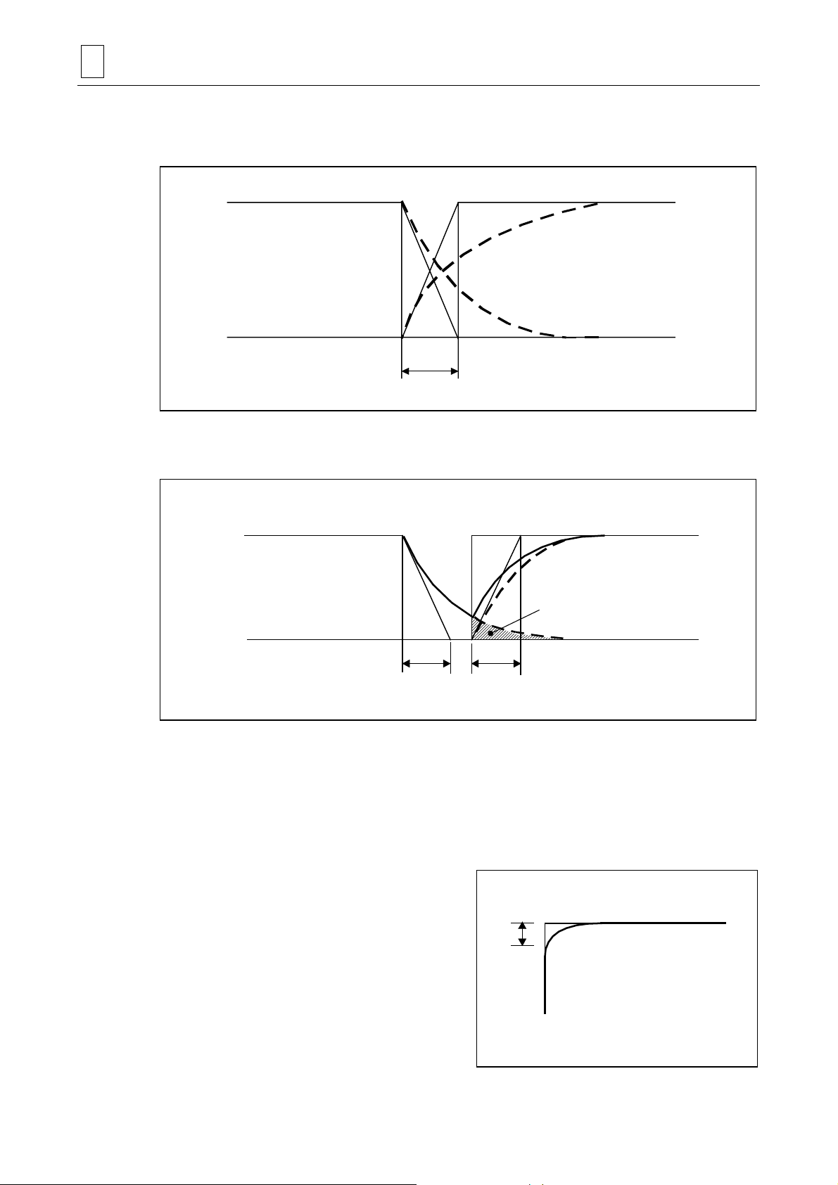
7 FEED FUNCTI ONS
4. Detailed description
A. Continuous cutting feed commands
Preceding block
Ts
Fig. 7-2 Continuous cutting feed commands
B. Cutting feed commands with in-position status check
Preceding block Next block
Ts Ts
Next block
TEP039
Lc
TEP040
Fig. 7-3 Block-to-block connection in cutting feed in-position status check mode
In Fig. 7-2 and 7-3 above,
Ts: Cutting feed acceleration/deceleration time constant
Lc: In-position width
As shown in Fig. 7-3, in-position width Lc represents the remaining distance within the block
immediately preceding the next block to be executed.
The in-position width helps keep any
rounding of workpieces during corner
cutting within a fixed level.
If rounding of workpieces at corners is to
Lc
Next block
be completely suppressed, include dwell
command G04 between cutting blocks.
Preceding block
TEP041
7-8
 Loading...