

Page 1

PROGRAMMING MANUAL
for
MAZATROL FUSION 640M
MAZATROL FUSION 640M 5X
MAZATROL FUSION 640M NEXUS
MAZATROL PROGRAMMING
MANUAL No. : H735PG0019E
Serial No. :
Before using this machine and equipment, fully understand the contents of this
manual to ensure proper operation. Should any questions arise, please ask the
nearest Technical/Service Center.
IMPORTANT NOTICE
Be sure to observe the safety precautions described in this manual and the contents of the
1.
safety plates on the machine and equipment. Failure may cause serious personal injury or
material damage. Please replace any missing safety plates as soon as possible.
No modifications are to be performed that will affect operation safety. If such modifications are
2.
required, please contact the nearest Technical/Service Center.
For the purpose of explaining the operation of the machine and equipment, some illustrations
3.
may not include safety features such as covers, doors, etc. Before operation, make sure all
such items are in place.
This manual was considered complete and accu rate at the time of public ation, how ever, due to
4.
our desire to constantly improve the quality and specification of all our products, it is subject to
change or modification. If you have any questions, please contact the nearest Technical/Service
Center.
Always keep this manual near the machinery for immediate use.
5.
If a new manual is required, please order from the nearest Technical/Service Center with the
6.
manual No. or the machine name, serial No. and manual name.
Issued by Manual Publication Section, Yamazaki Mazak Corporation, Japan
03. 2004
Page 2

Page 3
SAFETY PRECAUTIONS
Preface
Safety precautions relating to the CNC unit (in the remainder of this manual, referred to simply as
the NC unit) that is provided in this m achine are explained below. Not only the persons who
create programs, but also those who operate the machine must thoroughly understand the
contents of this manual to ensure safe operation of the machine.
Read all these safety precautions, even if your NC model does not have the corresponding
functions or optional units and a part of the precautions do not apply.
Rule
1. This section cont ains the precautions t o b e obs er ve d as to the working methods and s tates
usually expected. Of course, however, unexpec ted operations and/or un expected working
states may take place at the user site.
During daily operation of the machine, therefore, the user must pay extra careful attention to
its own working safety as well as to observe the precautions described below.
2. Although this manual c ontains as great an amount of information as it can, since it is not
rare for the user to perfor m the operations that ov erstep the manufactur er-assumed ones,
not all of “what the user ca nnot perform” or “what the us er must not perform” c an be fully
covered in this manual with all such operations taken into consideration beforehand.
It is to be understood, therefore, that functions not clearly written as “executable” are
“inexecutable” functions.
SAFETY PRECAUTIONS
3. The meanings of our safety precautions to DANGER, WARNING, and CAUTION are as
follows:
: Failure to follow these instructions could result in loss of life.
DANGER
: Failure to obs erve t hese instructi ons could r esult in ser ious harm to a hum an
life or body.
WARNING
: Failure to obs erve these instructions could result in m inor injuries or serious
machine damage.
CAUTION
HGENPA0029E
S-1
Page 4

Basics
SAFETY PRECAUTIONS
! After turning power on, keep hands away from the keys, buttons, or switches of the
operating panel until an initial display has been made.
WARNING
! Before proceeding to th e next operations, full y check that correct data has b een entered
and/or set. If the operator performs operations without being aware of data errors,
unexpected operation of the machine will result.
! Before machining workpieces, perform operational tests and m ake sure that the machine
operates correctly. No workpieces must be machined without confirmation of normal
operation. Closely check the accuracy of programs by executing override, single-block, and
other functions or b y operating the machine at no load. Also, full y utilize tool path check ,
solid check, and other functions, if provided.
Make sure that the appropriate feed rate and rotational speed are designated for the
!
particular machining requirements. Always understand that since the maximum usable feed
rate and rotational spe ed are det er mined by the specificat ions of the to ol to b e us ed , th os e
of the workpiece to be m achined, and various ot her factors, actual c apabilities diff er from
the machine specif ications listed in this manual. If an inappropriate fee d rate or rotationa l
speed is designated, the workpiece or the tool may abruptly move out from the machine.
! Before executing correction functions, fully check that the direction and amount of
correction are correct. Unexpected operation of the machine will result if a correction
function is executed without its thorough understanding.
Param eters are set to the optim um standard m achining conditi ons prior to sh ipping of the
!
machine from the fac tor y. In princ iple, these settings s houl d not be m odif ied. If it b ecom es
absolutely necessary to modify the settings, perform modifications only after thoroughly
understanding the func tions of the correspondin g parameters . Modifications us ually aff ect
any program. Unexpected oper ation of the machine will resu lt if the settings are modified
without a thorough understanding.
Remarks on the cutting conditions recommended by the NC
! Before using the following cutting conditions:
- Cutting conditions that are the result of the MAZATROL Automatic Cutting Conditions
WARNING
Determination Function
- Cutting conditions sugg es ted b y the Machini ng Na vig atio n Fu nctio n
- Cutting conditions for tools t hat are suggested to be used b y the Machining Navigation
Function
Confirm that every necessary precaution in regards to safe machine setup has been taken –
especially for workpiec e fixt uring /c lamping and tool setup.
! Confirm that the machine door is securely closed before starting machining.
Failure to confirm safe machine setup may result in serious injury or death.
S-2
Page 5

Programming
WARNING
SAFETY PRECAUTIONS
! Full y check that the s ettings of the c oordinate s ystem s are c orrect. Even if th e des ignated
program data is correct, errors i n the s ystem s ettings m a y cause the m ac hine to operate in
unexpected places a nd the work piece to abruptl y m ove out fr om the m achine in the e vent
of contact with the tool.
! During surface velocit y hold control, as the current work piece coordinates of the surf ace
velocity hold contr ol axes appr oach zeroes , the spind le speed inc reases signif icantly. F or
the lathe, the work piece m ay even c om e off if the chuc k ing forc e decreas es. Safety speed
limits must therefore be observed when designating spindle speeds.
! Even after inch/metric system selection, the units of the programs, tool information, or
parameters that have been register ed until that t ime are not c onverted. Full y check these
data units before operating the machine. If the machine is oper ated without checks being
performed, even exis ting correct programs may cause the machine to oper ate differently
from the way it did before.
! If a program is executed that includes the absolute data commands and relative data
commands taken in the r everse of their origin al meaning, totall y unexpected operation of
the machine will result. Recheck the command scheme before executing programs.
! If an incorrect plane selection command is issued for a machine action such as arc
interpolation or fixed-cyc le m ac hini ng, the too l may collide with the work piece or part of the
machine since the m otions of the control axes assum ed and those of actual ones will be
interchanged. (This precaution applies only to NC units provided with EIA functions.)
! The mirror image, if made valid, changes subse quent machine actions si gnificantly. Use
the mirror image f unction only after th oroughly unders tanding the abo ve. (This pr ecaution
applies only to NC units provided with EIA functions.)
If machine coordinate system commands or reference position returning commands are
!
issued with a correction function remaining made valid, correction may become invalid
temporarily. If this is not thoroughly understood, the machine may appear as if it would
operate against the ex pectations of the oper ator. Execute the above com mands only af ter
making the correspondin g correction functio n invalid. (This precaution a pplies only to NC
units provided with EIA functio ns .)
The barrier function performs interference checks based on designated tool data. Enter the
!
tool information that m atches the tools t o be actual ly used. Other wise, the barr ier function
will not work correctly. (This precaution applies only to the M640MT/MT 5X/T/T NEXUS/TN
and M640M Pro/MT Pro.)
The system of G-code and M-code commands differs between the machines equipped with
!
M640M Pro (e-Series such as the INTGEREX e-410, e-650 and e-1060) and the machines
equipped with M640MT/MT 5X/T/T NEXUS/TN/MT Pro (such as the INTGEREX non eSeries, the SQT Series, the MPX Series and the QTN Series).
Issuance of the wrong G-code or M-code command results in totally non-intended machine
operation. Thoroughly understand the system of G-code and M-code commands before
using this system.
Sample program Machine with M640M Pro
S1000M3
S1000M203
The milling spindle rotates at 1000 min–1. The turning spindle rotates at 1000 min–1.
The turning spindle rotates at 1000 min–1. The milling spindle rotates at 1000 min–1.
S-3
Machine with M640MT/MT 5X/T/
T NEXUS/TN/MT Pro
Page 6

SAFETY PRECAUTIONS
! For the machines equi pped with M640M Pro (e-Ser ies such as the INTGEREX e- 410, e-
650 and e-1060), programmed coordinates can be rotated using an index unit of the
MAZATROL program and a G68 command (coordinate rotate command) of the EIA
program. However, for ex ample, when the B-axis is rota ted through 180 degrees around
the Y-axis to implement machining with the turning spindle No. 2, the plus side of the X-axis
in the programmed coordinate system faces downward and if the program is created
ignoring this fac t, the resulting movement of the tool to unexpected posit ions may incite
collisions.
To create the progr am with the plus sid e of the X - ax is or ie nted in an upward directio n, us e
the mirror function of the WPC shift unit or the mirror imaging function of G-code command
(G50.1, G51.1).
! After modifying the tool data specified in the program, be sure to perform the tool path
check function, the so lid check f unction, an d other f unctions , and conf irm that the program
operates properly. T he m odification of tool dat a ma y cause even a f ield-pro ven m achining
program to change in operational status.
If the user operates the machine without be ing aware of an y changes in program status,
interference with the workpiece could arise from unexpected operation.
For example, if the cutting edge of the tool during the start of automatic operation is present
inside the clearance- i nclu din g blank (unmachined wor kpiece) specified in t he c ommon unit
of the MAZATROL program, care is required since the tool will directly move from that
position to the approac h point because of no obstructions being judged to be pr esent on
this path.
For this reason, before starting automatic operation, make sure that the cutting edge of the
tool during the start of automatic operation is present outside the clearance-including
workpiece specified in the common unit of the MAZATROL program.
S-4
Page 7
CAUTION
SAFETY PRECAUTIONS
! If axis -by-axis independ ent positionin g is selecte d and simultaneous ly rapid f eed selected
for each axis, movem ents to the ending point wi ll not usually bec ome linear. Before using
these functions, therefore, make sure that no obstructions are present on the path.
If the machine employs sl iding surface structure, lubr ication may prove to be insuff icient
!
during continuous m icrof eed mac hining ( see Note 1 belo w), an d in the worst cas e, se izure
of the sliding surface could result. For these reasons, the sliding surface needs to be
maintained in a wel l-lubricated con dition during s uch machining by, for exam ple, inserting
an oil-film forming program (see Note 2 below).
List of applicable models and intended axes (Models that employ sliding surface structure)
Classification Machine model Axes with sliding surface structure
Lathes INTEGREX 50Y X-axis, Y-axis, Z-axis
INTEGREX 50YB X-axis, Y-axis, Z-axis
INTEGREX 70Y X-axis, Y-axis, Z-axis
INTEGREX 70YB X-axis, Y-axis, Z-axis
SLANT TURN 450 X-axis, Z-axis
SLANT TURN 50N X-axis, Z-axis
SLANT TURN 60N X-axis, Z-axis
SLANT TURN 80N X-axis, Z-axis
TURNING CENTER M-4N X-axis, Z-axis
TURNING CENTER M-5N X-axis, Z-axis
POWER MASTER X-axis, Z-axis
QUICK TURN 40 X-axis, Z-axis
MEGA TURN series X-axis, Z-axis
SUPER QUADREX 200/250 Z2-axis
SUPER QUICK TURN 200/250MY Y-axis
SUPER QUICK TURN 300MY Y-axis
FJV-35/50/60 Z-axisVertical machining
centers
MTV-515/655/815 Z-axis
V-40/60 Z-axis
For further details and m ore specific examples, refer to the relevant Machine Operating
Manual, Part 4, Section 1-2, “Precautions for Microfeed Machining (Models th at Employ
Sliding Surface Structur e) ”.
Note 1: Cont inuous m ic rofeed machining refers to the oper ation in which t he m ovem ent of the
intended feed axis through strokes shorter than those required for lubrication is
continuously repeated.
Note 2: T he oil-film form ing program refers to a program that creates an oil f ilm on the slidin g
surface by moving the intended machining axis over a long stroke during machining.
S-5
Page 8

Operations
WARNING
SAFETY PRECAUTIONS
! Single-block, feed hold, and override functions can be made invalid using system variables
#3003 and #3004. Execution of this means the important modification that makes the
corresponding operations invalid. Before using these variables, therefore, give thorough
notification to re lated persons. Also, the operator must check the s ettings of the system
variables before starting the above operations.
! If manual intervention during automatic operation, machine locking, the mirror image
function, or other functions ar e execut ed, t he work piece coor dinat e system s will usua ll y be
shifted. When making machine restart after manual intervention, machine locking, the
mirror image f unction, or other functions , consider the resu lting amounts of shift and take
the appropriate measures. If operation is restarted without any appropriate measures being
taken, collision with the tool or workpiece may occur.
! Use the dry run f unction to check the machine for norm al operation at no load . Since the
feed rate at this tim e becomes a dry run r ate different from the program-designated feed
rate, the axes may move at a feed rate higher than the programmed value.
After operation has been stopped temporarily and insertion, deletion, updating, or other
!
commands executed for the active program, unexpected operation of the machine may
result if that program is restarted. No such commands should, in principle, be issued for the
active program.
CAUTION
! During manual operation, fully check the directions and speeds of axial movement.
! For a machine that requires manual homing, perform manual homing operations after
turning power on. Since the software-controlled stroke limits will remain ineffective until
manual homing is completed, the machine will not stop even if it oversteps the limit ar ea.
As a result, serious machine damage will result.
Do not design ate an incorrect puls e multiplier when performing m anual pulse handle f eed
!
operations. If the m ultip lier is se t to 100 t im es and the han dle op erated i nadver tent ly, axia l
movement will become faster than that expected.
S-6
Page 9

OPERATIONAL WARRANTY FOR THE NC UNIT
OPERATIONAL WARRANTY FOR THE NC UNIT
The warranty of the manufacturer does not co ver a n y troub le ar is i ng if the NC un it is used for its
non-intended purpose. Take notice of this when operating the unit.
Examples of the trouble arising if the NC unit is used for its non-intended purpose are listed
below.
1. Trouble associated with and caused by the use of any commercially available software
products (including user-created ones)
2. Trouble associated with and caused by the use of any Windows operating systems
3. Trouble associated with and caused b y the use of any commercially available computer
equipment
Operating Environment
1. Ambient temperature
During machine operation: 5° to 40°C (41° to 104°F)
Note: When power is turne d on, if the therm al s ensor de tects an am bient t em perature und er
5°C, the hard disk warm-up status indic ator lamp will ligh t up and the NC un it will not
start operating at once. After autom atic heating of the hard disk by its int ernal heater,
the lamp will go out and the NC unit will start. It takes about 20 minutes for temperature
to increase from 0 to 5° C in order to avoid condensation due to sudden changes in
temperature.
2. Relative humidity
During machine operation: 30 to 75 % (without bedewing)
Note: As humidity increases, insulation deteriorates causing electrical component parts to
deteriorate quickly.
S-7
Page 10

- NOTE -
OPERATIONAL WARRANTY FOR THE NC UNIT
S-8
E
Page 11

CONSTRUCTION
Introduction
Part 1 MAZATROL PROGRAMMING PROCEDURES
Chapter 1 MAZATROL PROGRAM
Chapter 2 SYSTEM OF COORDINATES
Chapter 3 FUNCTION OF KEYS AND SWITCHES
Chapter 4 PROCEDURE BEFORE PERFORMING THE MACHINING
Part 2 MAZATROL PROGRAM FUNCTIONS
Chapter 1 CALLING UP AND THE END OF THE PROGRAM DISPLAY
Chapter 2 EDITION OF DATA
Chapter 3 WINDOW FUNCTIONS
Chapter 4 PROGRAM CREATION
Chapter 5 PRIORITY FUNCTION FOR THE SAME TOOL
Chapter 6 COORDINATES MEASUREMENT FUNCTION
Appendix
Chapter 7 TPC DATA CREATION
Chapter 8 BACKGROUND PROGRAMMING
Chapter 9 CASE OF APPEARANCE OF ALARM
Chapter 10 THREE-DIGIT G-FORMAT
Appendix 1 LIST OF M CODES
Appendix 2 PROGRAM EXAMPLES
Appendix 3 WHAT TO DO IN SUCH A CASE?
GC-1
Page 12

- NOTE -
GC-2
E
Page 13

Introduction
This manual describes only programming based on the MAZATROL language of the
MAZATROL FUSION 640M system. The description given in this manual assumes that the
readers have already read the relevant Operating Manual and thoroughly understood its
contents.
Programming in the MAZATROL langua ge uses an inter ac ti ve method that allows the system to
be operated in accordance with the messages displayed on the CRT monitor. Thus, even a user
who is to operate the system for the first time can readily create and edit programs.
Carefully read this manual and the Operating Manual to correctly operate the MAZATROL
FUSION 640M system and use its capabilities to their maximum.
H735P0A011E
NOTE:
The MAZATROL FUSIO N 640M controls the m achining center by digital calculat ion, but it is
possible that the m achining cannot be perf ormed because of the process ing of a calculation
error. Before proceed ing with autom atic operat ion therefore, do not fail to ins pect the path of
the tool on the display in order to verify that the machining is being done correctly.
1
Page 14
Organization of this manual
The following outlines the organization of this manual:
Part Title
1MAZATROL
PROGRAMMING
PROCEDURES
2MAZATROL
PROGRAM
FUNCTIONS
APPENDIX
Upper row – Directions for using the chapter
Lower row – Contents of the chapter
Those who are going to set up a MAZATROL program for the first time must first read this
part. Actually operate the MAZATROL FUSION 640M system from the beginning as
directed in Chapter 4, “PROCEDURE BEFORE PERFORMING THE MACHINING.” You
will then be able to roughly understand the entire operating procedure from tool
registration to creation of a MAZATROL program. Those who already have an
experience in creating a program using the MAZATROL M-1, M-2, M-32 or MAZATROL
FUSION 640M system will be able to understand the functions and usage of the M640M
system just by directly reading Part 2, “MAZATROL PROGRAM FUNCTIONS.”
The program architecture, coordinates systems, and operation keys are discussed here
as the basic information required for program creation in MAZATROL language. In
addition to the program creation procedures, successive processing procedures up to
machining are described in order after the discussion of the basic information.
Use the functions of the MAZATROL FUSION 640M system only after understanding the
MAZATROL program architecture and program creation procedures described in Part 1.
Also, use this part as a reference whenever required, such as in cases where you have
only a slight idea (or have forgotten) how to use a function, as you create a MAZATROL
program.
How to call up the
details of each function are described here. How to create programs in the background
mode, and how to act in the event of alarms are also discussed.
An M-code list, sample programs, and a Q&A (Questions and Answers) list are
contained. Read this appendix as appropriate.
PROGRAM
display, how to edit data, how to use a function, and
How to use this manual
Next, how to use this manual is briefly described below.
1. In Part 2, “MAZATROL PROGRAM FUNCTIONS,” where the operating procedures for
carrying out the MAZAT RO L la ngu age func t ions are described, the order of s el ect in g menu
items is indicated at “Menu selection.” Use the section as quick reference during menu
selection.
2. In Part 2, “MAZATROL PROGRAM FUNCTIONS,” where the operating procedures are
described, the arrow “!” under the description of each step of the procedure is followed bya
description of the results of the particular operation.
Example:
(1) Press the
! The message
SEARCH
menu key.
SEARCH DATA?
will be displayed and the menu will change to the
following address menu:
The section underlined above denotes the results of the operation.
2
E
Page 15

PART 1
MAZATROL PROGRAMMING
PROCEDURES
Part 1 describes the architecture of MAZATROL programs, coordinate systems,
the keys to be used for programming, and simplified programming procedures.
H735P10017E
Page 16

Page 17

CONTENTS
Page
1 MAZATROL PROGRAM...................................................................... 1-1
2 SYSTEM OF COORDINATES............................................................. 2-1
2-1 Machine Coordinates System............................................................................ 2-1
2-2 Workpiece Coordinates System......................................................................... 2-2
2-3 Machine Coordinates System and Workpiece Coordinates System.................. 2-3
2-4 Basic Coordinates.............................................................................................. 2-3
2-5 Auxiliary Coordinates......................................................................................... 2-4
3 FUNCTION OF KEYS AND SWITCHES..............................................3-1
4 PROCEDURE BEFORE PERFORMING THE MACHINING................4-1
4-1 Diagram of Preparation for the Machining.........................................................4-1
4-2 Part Drawings and Stock Materials.................................................................... 4-3
4-3 Registration of Tools.......................................................................................... 4-5
4-3-1 Calling up the TOOL FILE display .........................................................................4-5
4-3-2 Registration of tools...............................................................................................4-6
4-4 Creation of Simple Programs............................................................................. 4-9
4-4-1 Program structure..................................................................................................4-9
4-4-2 Calling up the PROGRAM display.......................................................................4-10
4-4-3 Assigning workpiece numbers.............................................................................4-11
4-4-4 Creating a program..............................................................................................4-13
4-4-5 Creation of common unit .....................................................................................4-13
4-4-6 Creation of basic coordinates system unit ...........................................................4-15
C-1
Page 18

4-4-7 Face machining unit ............................................................................................4-17
4-4-8 Line machining unit..............................................................................................4-27
4-4-9 Point machining unit (1).......................................................................................4-37
4-4-10 Point machining unit (2).......................................................................................4-46
4-4-11 End unit...............................................................................................................4-53
4-4-12 End of the program..............................................................................................4-54
4-5 Registration of Tools in a Tool Data File.......................................................... 4-56
4-5-1 Pocket numbers and tool numbers......................................................................4-56
4-5-2 TOOL DATA display............................................................................................4-57
4-5-3 TOOL LAYOUT display .......................................................................................4-59
4-5-4 Registration of tools.............................................................................................4-62
4-6 Check of the Machining Path........................................................................... 4-65
C-2
E
Page 19

1 MAZATROL PROGRAM
The machining MAZ ATROL program of a work piece consists in principle of the following four
units:
1. Common unit
This concerns a un it which is obligatoril y entered in the pr ogram head . It specifies the comm on
data to a program assembly such as the material, the initial point, the machining of several
workpieces, etc.
2. Basic coordinates system unit
Use to specify the value of the coordinates (basic coordinates) of the workpiece zero point in the
machine coordinates system.
3. Machining unit
Use to specify the data concerning the machining method and the machining form.
The machining unit is available in the following three types:
Point machining unit
MAZATROL PROGRAM
1
-Drilling
- RGH CBOR machining
- RGH BCB machining
- Reaming
- Tapping
-Boring
- Back boring
- Circular milling
- Counterbore-tapping
Line machining un i t
- Central linear machining
- Right-hand linear machining
- Left-hand linear m achining
- Outside linear machining
- Inside linear machining
- Right-hand chamfering
- Left-hand chamfering
- Boring of through hole
- Boring o f stepped through hole
- Boring of non-through hole
- Boring o f stepped n on-through hole
Face machining unit
- Face milling
- End milling-top
- End milling-step
- Pocket milling
- Pocket milling-mountain
- Pocket milling-valley
- End milling-slot
- 3-D (option)
H735P1A010E
- Outside chamfering
- Inside chamfering
Moreover, the necessary data are specified in the following two sequences:
Tool sequence ............... Use to specify the data concerning the name of the tool and the
movement of the tool.
Shape sequence ............ Use to specify the data related to the machining dimensions.
1-1
Page 20

1
MAZATROL PROGRAM
4. End unit
Unit created at the end of program.
Also, the following units are entered when necessary.
5. Auxiliary coordinates system unit
Use to specify the auxiliary coordinates system (OFFSET).
6. Special mode unit
There are the following special mode units. It is possible that these units marked with an asterisk
(*) can not be used or executed in certain machine models.
M code............................ Output of M code
Sub-program................... Calling up a sub-program
Pallet changing*.............. Changing of pallet
Indexing*......................... Use to specify the angle of the indexing table.
Process end.................... Delimits the useful scope of the priority function for the same tool.
7. Manual program mode unit
This unit is entered t o establish a program cor responding to the EIA/I SO program using the G
and M codes which permits performing minute movement or a movement other than machining.
8. MMS unit
Automatic measur ement of a basic coordinates s ystem (WPC). MMS unit cann ot be used for
certain machines or will not be performed even if programmed.
1-2
E
Page 21

2 SYSTEM OF COORDINATES
(
)
–Y–
–
(
)
In the preparation of the pr ogram, a system of c oordinates is used for introduci ng th e pos it ion of
the machining and the form of the machining.
The system of coordinat es of the machining cen ter consists of thr ee axes of coordinat es which
each cross the reference zero point at right angles.
An arbitrary point found in this system of coordinates can be defined by the value of the
coordinates in the 3 axes (X, Y and Z).
There are two types of systems of coordinates:
- Machine coordinates system
- Workpiece coordinates system
Z axis
SYSTEM OF COORDINATES
2
X axis
Fig. 2-1 Coordinates system
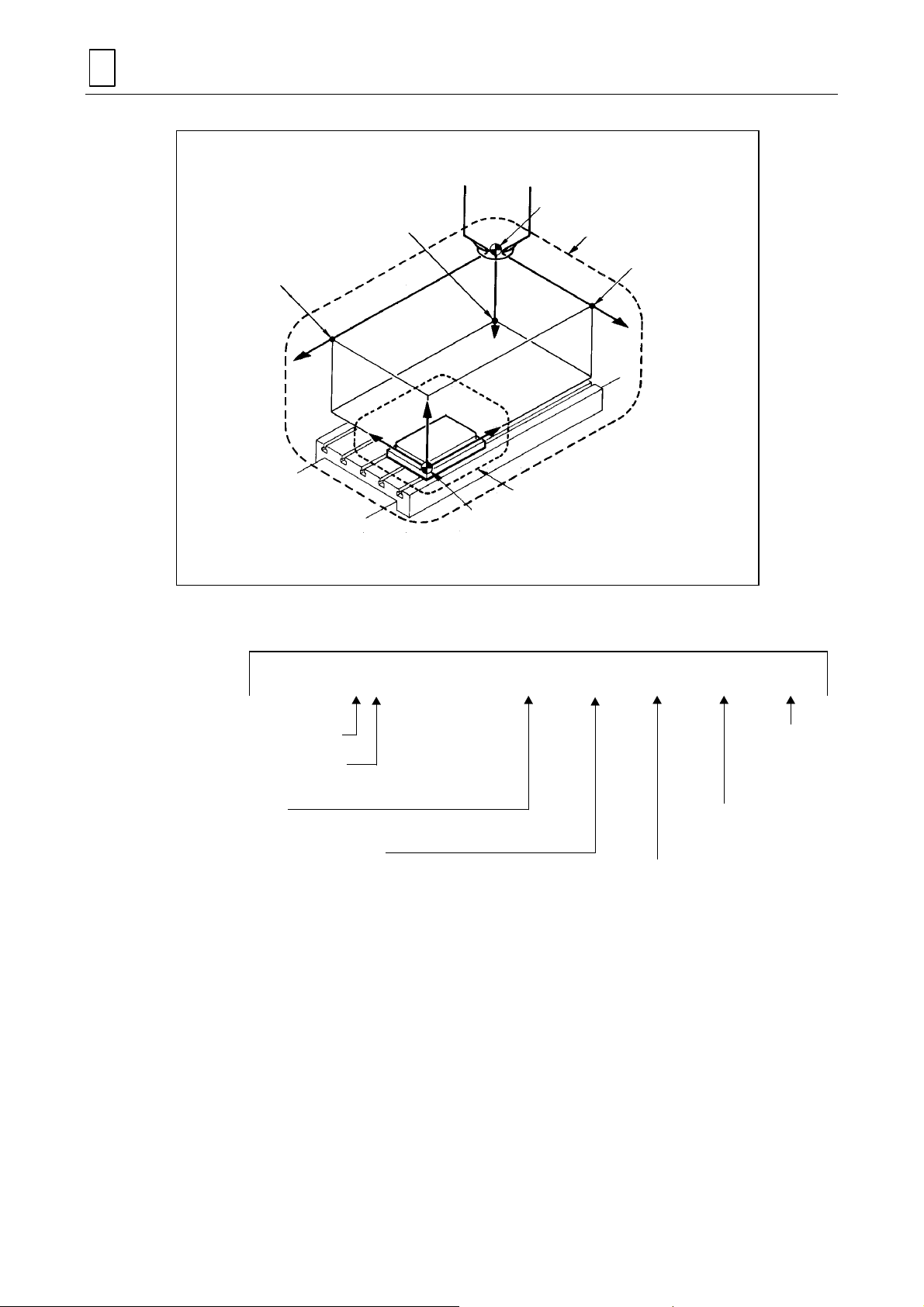
2-1 Machine Coordinates System
The machine actually m oves in its own system of coordinat es called the machine coordinates
system. A point of reference in this system of coordinates is known as machine zero point.
Generally, the machine coordin ates system has the machining zone on the side of the minus
(negative) direction from the machine zero point.
Note:
The following figure represents the case of vertical machining center.
Machining zone
Machine coordinates system
Axis of X
coordinate
X
+Z
+Y +X
Machine zero point
X0, Y0, Z0
Axis of Z
coordinate
Z
Reference point zero
Y axis
M3P001
Axis of Y
coordinate
Table
NM210-00510
Fig. 2-2 Machine coordinates system
H735P1B010E
2-1
Page 22

2
SYSTEM OF COORDINATES
2-2 Workpiece Coordinates System
If the program is prepared on the bas is of the m achine coordinates system, the entering of the
machining position and of the form of machining is very complex, tedious and inflexible.
Consequently, a temporary reference point is taken in the machine coodinates system for
preparing the program.
The point thus taken is called the workpiece zero point, and the system of coordinates taking this
point as reference is called the workpiece coordinates system.
Example:
Plan of the workpiece
P2
R5
P1
M3P002
100
95
Zero point of
the workpiece
to be taken
60
20
P3
R5
50
φ
5
5
50
M8 tapped holes
(4 places)
10-mm diameter
drilled hole
100
145
150
- When the dim ensions are entered of the configuration on the basis of the ab ove plan of the
workpiece, the bottom left hand corner is taken as the workpiece zero point.
- In this case, the value of the coordinates of the configuration is the following:
Workpiece zero point = ( 0, 0, 0)
P1 = (150, 0, 0)
P2 = (150, 100, 0)
P3 = ( 0, 100, 0)
The adoption of the work piece zero point facilitates the enter ing of the machining dimensions
and therefore the programming.
2-2
Page 23

SYSTEM OF COORDINATES
2-3 Machine Coordinates System and Workpiece Coordinates System
The relationship bet ween the machine coordinates s ystem and workpiece coord inates system
when workpiece has been mounted on the table of a machine is shown below.
Machine coordinates system
Machine coordinates system
Workpiece coordinates system
2
<Model V, double column type> <Model V>
The above relationship may slightly differ according to the type of machine being used.
Note:
Fig. 2-3 Machine coordinates system and workpiece coordinates system
2-4 Basic Coordinates
The machine moves in the machine coordinates system whilst the program is prepared
depending on the workpiece coordinates system.
NM210-00511
<Model H>
NM210-00512
Machine coordinates system
Workpiece coordinates system
NM210-00513
It is necessary therefore to enter in the program, the position relation between the machine
coordinates system and the workpiece coordinates system.
The unit of entry is called the basic coordinates unit.
The basic coordinates are entered as values of the coordinates of the workpiece zero point in the
machine coordinates system.
The unit of the basic coord inates is entered by utilizing the coord inates measurement function
after the workpiece is placed on the machine.
2-3
Page 24
2
(
)
A
SYSTEM OF COORDINATES
Basic
coordinate Z
Basic
coordinate X
Z
−
X
−
+Z
+Y
Fig. 2-4 Basic coordinates
+X
Workpiece zero point
Example of entering of the basic coordinates unit:
Machine zero point
Machine coordinates system
Basic coordinate Y
Y
−
Workpiece coordinates system
NM210-00514
UNo.
1
Basic coordinates unit
No. of basic coordinates
unit
Basic coordinate X
Example: –500
Basic coordinate Y (Exam pl e: –300)
2-5 Auxiliary Coordinates
The auxiliary coordinates are used for offsetting the workpiece zero point to any position in order
to further facilitate the preparation of the program.
The auxiliary coordinates unit (OFFSET) is entered as a value of offsetting in the workpiece zero
point.
UNIT
WPC-0
ADD. WPC X
-500.Y-300.
th
0.
Basic coordinate Z
(Example: –200)
ngle formed by the axes X and Y of the
machine coordinates system and the axes X and
Y of the workpiece coordinates system.
Z
-200.
4
0.
Coordinate or
angle of 4th
axis, if there
is one.
2-4
Page 25

1. Example of entering of auxiliary coordinates
+y
0
R
0
70
Workpiece zero point
In this example, the entering of the position of hole P1 requires a very complicated
calculation.
P2
50
P1
20
30°
SYSTEM OF COORDINATES
+x
0
M3P003
2
P1 = (70 + 50 ×
3
2
, 50 ×
1
)
2
However, the use of auxiliary coordinates permits performing this entering easily.
+y
1
P2
20
P1
R
R
0
70
1
50
Zero point offset in auxil iary
coordinates mode
30°
+x
1
M3P004
As the figure above s hows, positions P1 and P2 ar e entered as follows by off setting the
workpiece zero point to R1.
P1 = (50, 0)
P2 = (50, 20)
In this case, the auxiliary coordinates unit to be programmed is as follows:
UNo.
2
Auxiliary coordinates unit
Offsetting on X axis
UNIT
OFFSET
U (X)
70.
V (Y)
0.
Offsetting on Y axis
D (th)
30.
Offsetting on Z axis
Angle with relation
to workpiece
coordinates system
2-5
W (Z)
0.
Page 26
2
SYSTEM OF COORDINATES
2. Cancellation of auxiliary coordinates
The system of auxiliary coordinates is voided in the following cases:
A. The system of aux iliary coordi nates specif ied in a sub- program is void ed at the t ime of the
return on the main program.
When the main program contains a system of auxiliary coordinates, th e return is made to
this system of auxiliary coordinates.
B. The system of auxiliar y coordinates is voided when a new s ystem of basic coordinates is
introduced. In this case, the state without a system of auxiliary coordinates is assumed.
(When the system of basic coordinates was specified in the sub-program as shown in
Figure 2-5, the retur n to the main program has the effect of voiding the s ystem of auxiliar y
coordinates of the main program.)
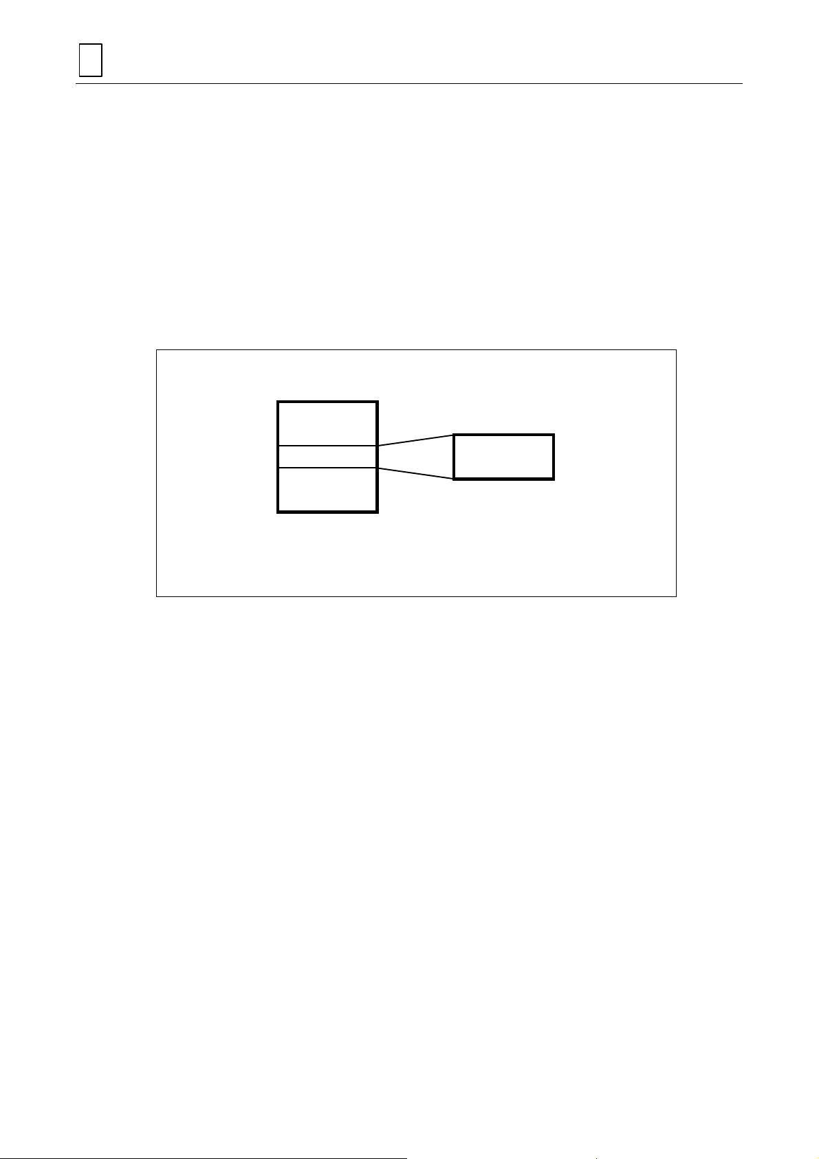
Main program
WPC-1
Machining [1]
Subprogram
Machining [2]
WPC is a code that signifies the bas i c coordinates system.
Machining [2] is performed under the coordinates system of WPC-2.
Fig. 2-5 Basic coordinates system after execution of subprogram
Sub program
WPC-2
M3P005
2-6
E
Page 27

3 FUNCTION OF KEYS AND SWITCHES
A MAZATROL program can be c reated usin g onl y the k eys and switches ind icated i n the d otted
portion on the operating panel shown in Fig. 3-1 and Fig. 3-2.
FUNCTION OF KEYS AND SWITCHES
3
H735P1C017E
3-1
Page 28

FUNCTION OF KEYS AND SWITCHES
3
1
3
5
7
6
8
4
2
9
D735P0001
Fig. 3-1 Keys and switches used for creating a MAZATROL program <M640M, M640M-5X> ( portion)
3-2
Page 29

FUNCTION OF KEYS AND SWITCHES
3
1
3
5
7
6
8
4
2
9
D735P0001’
Fig. 3-2 Keys and switches used for creating a MAZATROL program <M640M NEXUS> ( portion)
3-3
Page 30

FUNCTION OF KEYS AND SWITCHES
3
Table 3-1 Functions of keys and switches
No. Name Description
1 Display selector key
2 Menu selector key Press this key to select menu that is displayed on the bottom of the screen.
3 Menu keys
4 Cursor keys
5 Numeric keys
6 Input key Press this key to register keyed-in data in the data display area.
7 Clear key
8 Data cancellation key
9 Page keys
Press this key to select between displays. Depression of this key causes a display
selection menu to be displayed in the menu display area.
A specific key is assigned to each of ten menu data that are displayed in the menu
display area. Press the appropriate key to carry out the operation speci fied by the
particular display or to input the data specified by the particular display.
Press the apropriate key to move the cursor in the desired direction. If a cursor key
is pressed and held down, the cursor will move continuously in the corresponding
direction.
Use these keys to key in the numerics 0 to 9, the minus sign ( – ), and/or the
decimal point ( . ).
Press this key to cancel the data currently being displayed in the data selection
area. This key is also used for erasure of the alarm display.
Press this key to cancel the data that has been displayed in the data display area.
Depression of this key causes the data in the cursor position to be erased.
Press the appropriate key to move the cursor unit by unit. Pressing and holding
down the key will move the cursor unit by unit continuously.
Note: The numbers in the No. column corresponds to those in Fig. 3-1 and 3-2.
3-4
E
Page 31

PROCEDURE BEFORE PERFORMING THE MACHI NING
4 PROCEDURE BEFORE PERFORMING THE MACHINING
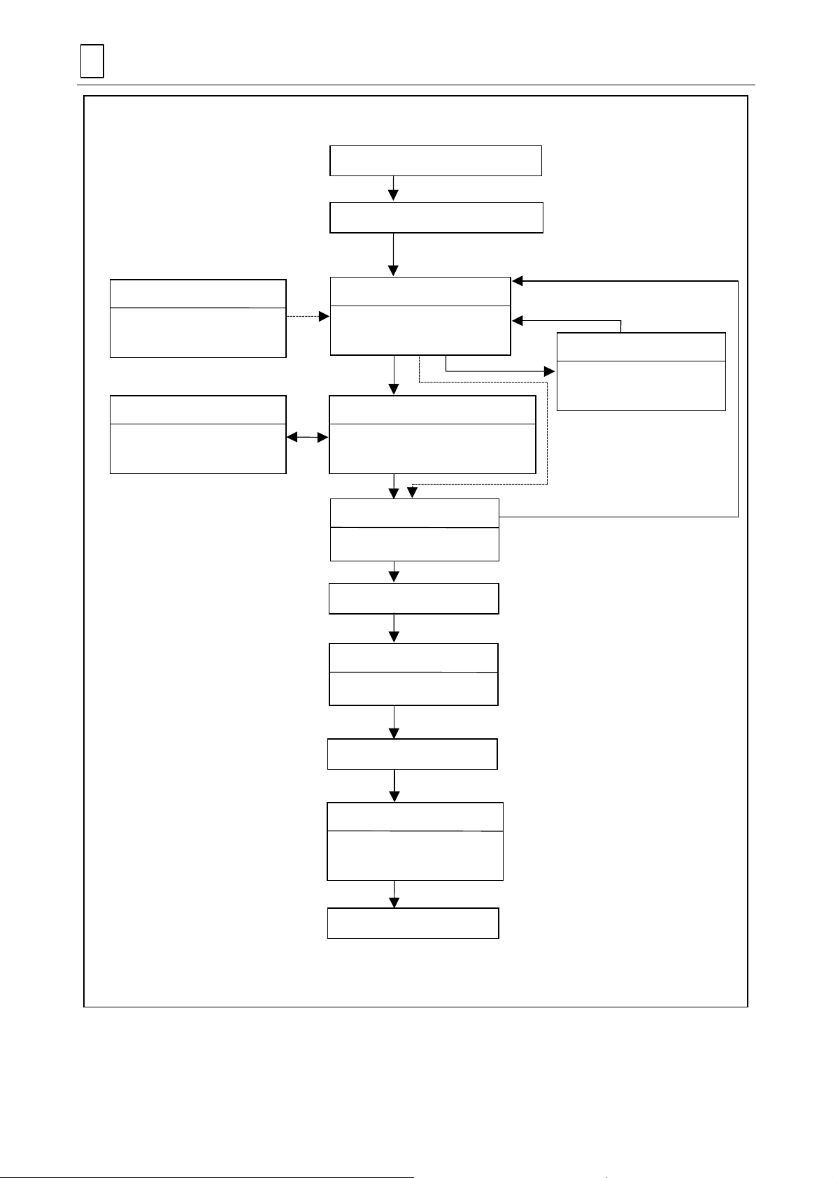
4-1 Diagram of Preparation for the Machining
To machine a workpiec e, it is essential to co ordinate the pr ogramming and th e preparations for
the tool and the workpiece. The f ollowing diagram shows the ge neral procedure to be foll owed
before performing the machining.
4
Note 1:
Note 2:
It is possible to m onitor the path of the tool even if the tool is not recorded in the tool
data. (The path of the tool is laid out by taking the diam eter of the tool = the nominal
diameter and the length of the tool = 0).
Automatic operation c an not be perform ed if the tool used is not recorded in the t ool
data.
H735P1D011E
4-1
Page 32
4
PROCEDURE BEFORE PERFORMING THE MACHINI NG
Preparation of part drawings
Reflection of the mounting workpiece
TOOL FILE
Recording of tools available in
the workshop
TOOL DATA
Verification of the tools
mounted on the tool magazine
display
display
PROGRAM
Preparation of machining
program op
TOOL LAYOUT
Recording of a tool to be mounted on
the tool magazine
TOOL PATH CHECK
Verification of path of tool form
Installation of tool
TOOL DATA
Measurement of length of tool
display
display
display
display
SHAPE CHECK
Verification of the programmed
form
display
Installation of workpiece
PROGRAM
Measurement of basic
coordinates
Automatic operation
Fig. 4-1 Procedure before performing the machining
display
4-2
M3P006
Page 33

4-2 Part Drawings and Stock Materials
g
(
)
φ
The following shows the part drawing for which a program is to be created in Section 4-4.
PROCEDURE BEFORE PERFORMING THE MACHI NING
4
R5
50
100 95
60
20
5
5
50
100
145
Fig. 4-2 Part drawing example
M8 tapped holes
(4 places)
10-mm diameter
drilled hole
150
Held by a vise, the part to be machined is shown below.
R5
10
20
Material: Carbon steel
Finish-machinin
surface:
∇, ∇∇
M3P007
NM210-00516
Machining of this part consists of the following four processes:
4-3
Page 34

4
PROCEDURE BEFORE PERFORMING THE MACHINI NG
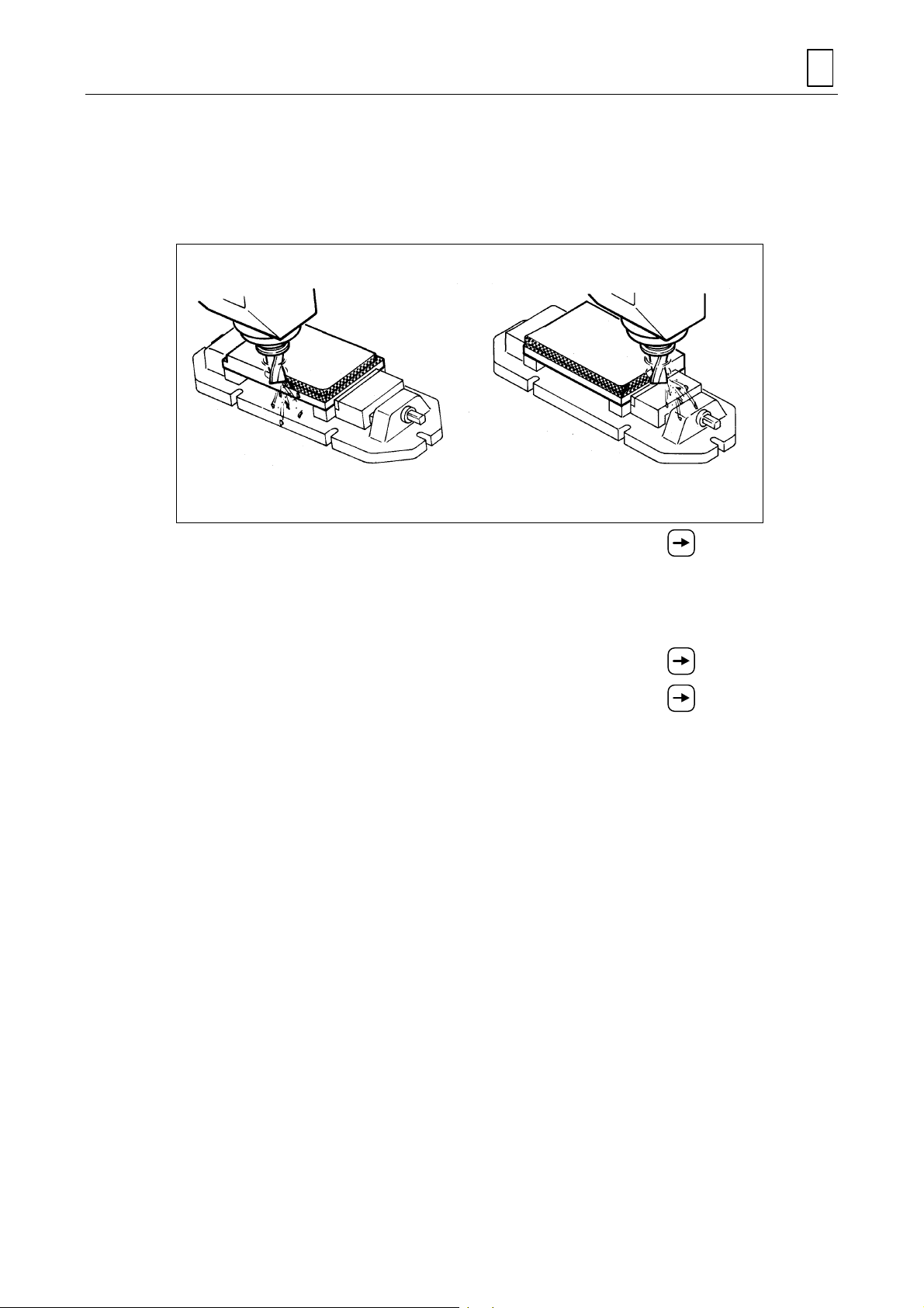
[1] Milling the top face of the workpiece. [2] End-milling the edges of the workpiece.
[3] Drilling a 10-mm diameter through-hole. [4] Drilling four M8 tapped holes.
NM210-00517 NM210-00518
NM210-00519 NM210-00520
4-4
Page 35

4-3 Registration of Tools
First, turn on the power to return the axes to the zero point.
Next, turn the reprogramming switch to the ENABLE position using the key.
Fig. 4-3 Reprogramming switch
PROCEDURE BEFORE PERFORMING THE MACHI NING
Turn
NM210-00521
4
Before creating the program, information on the tools located in the workshop must be registered
in a tool file. Unregistered tools cannot be used for programming or automatic run.
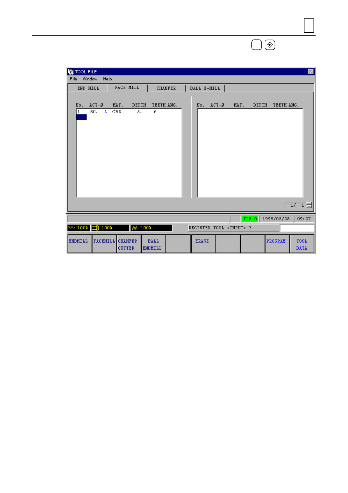
4-3-1 Calling up the TOOL FILE display
Call the
TOOL DATA
TOOL DATA
. Then press the menu key
display by pressing firs tly the disp lay selector k ey and then t he menu k ey
TOOL FILE
to call the following
TOOL FILE
display.
4-5
D735P0002E
Page 36

4
PROCEDURE BEFORE PERFORMING THE MACHINI NG
Register tools in the
End mill Face mill Chamfering cutter Ball-end mill
NM210-00522 NM210-00523 NM210-00524 NM210-00525
Tools other than these f our types do not nee d to be registered. T ool selection is automatically
made by the NC unit during programming.
4-3-2 Registration of tools
In this chapter, programming is to be carried out by using the two types of tools shown below.
TOOL FILE
display. The tools to be registered here are as follows:
End mill
Tool material:
Cemented carbide
Number of teeth: 2
30
10
NM210-00522
Fig. 4-4 Registered tools example
Face mill
Tool material:
Cemented carbide
Number of teeth: 6
5
80
NM210-00523
4-6
Page 37

PROCEDURE BEFORE PERFORMING THE MACHI NING
1. Registering the end mill
Using the page keys, search the display for the tool indicated as E-MILL 10. A.
Up to 256 tools can be registered. If the tool is found, this indicates that the tool has been
registered; therefore, proceed to the procedure described in “Registering the face mill.”
4
(1) Press the cursor key
!
The message
display area.
(2) Press the input key
!
The message
(3) Input an approximate tool-diameter value (in this example, input 10 by pressing numeric
1
keys
!
The message
(4) Input a specific code th at identifies the p articular tool ( in this example, input A b y pressing
menu key A).
and
NOMINAL DIAMETER?
0
and then pressing the input key ).
TOOL ID CODE <MENU>?
and position the cursor on an unregistered tool number.
REGISTER TOOL <INPUT>?
to register the tool.
will be displayed.
will then be displayed in the message
will be displayed.
D735P0003E
D735P0004E
!
The message
(5) Select the tool material from the tool material menu. Material names registered in the
CUTTING CONDITION
carbide by pressing menu ke y
!
The message
(6) Input the maximum depth to which the work piece can be cut in the axial directio n by one
cutting operation ( in this example, input 30 by press ing numeric keys
then pressing the input key
!
The message
TOOL MATERIAL <MENU>?
display are disp layed as menu (in this exam ple, select cemented
CARBIDE
MAX DEPTH OF CUT?
).
NUMBER OF TEETH?
).
will be displayed.
4-7
will be displayed.
will be displayed.
3
and
0
and
Page 38

4
PROCEDURE BEFORE PERFORMING THE MACHINI NG
(7) Input the number of teeth of the t ool ( in this ex am ple, input 2 b y pressing n um eric ke y
and then pressing the input key ).
!
Registration of the 10-mm diameter end mill will be completed as shown below.
2
2. Registering the face mill
The operations to be carried out are similar to those required for registering the 10-mm diameter
end mill. For brevity of description, the displayed message and key(s) to be pressed are noted to
the right and left respectively as shown below.
(1) Press the menu key
Check if the tool indica ted as 80. A is inc luded in the
the tool is found, then t his indicates th at the t ool has been reg istered. Thus , the oper ations
shown below are not required.
(2) Position the cursor on an unregistered tool number.
REGISTER TOOL <INPUT>?
(3)
NOMINAL DIAMETER?
(4)
TOOL ID CODE <MENU>
(5)
TOOL MATERIAL <MENU>
(6)
MAX DEPTH OF CUT?
(7)
FACE MILL
.................................................................
..................................................................
.
TOOL FILE (FACE MILL)
........................................................
?............................................................
? ........................................................
8 0
A
CARBIDE
5
D735P0005E
display. If
4-8
Page 39
PROCEDURE BEFORE PERFORMING THE MACHI NING
4
NUMBER OF TEETH?
(8)
!
This completes registration of the 80-mm diameter face mill as shown below.
...................................................................
6
4-4 Creation of Simple Programs
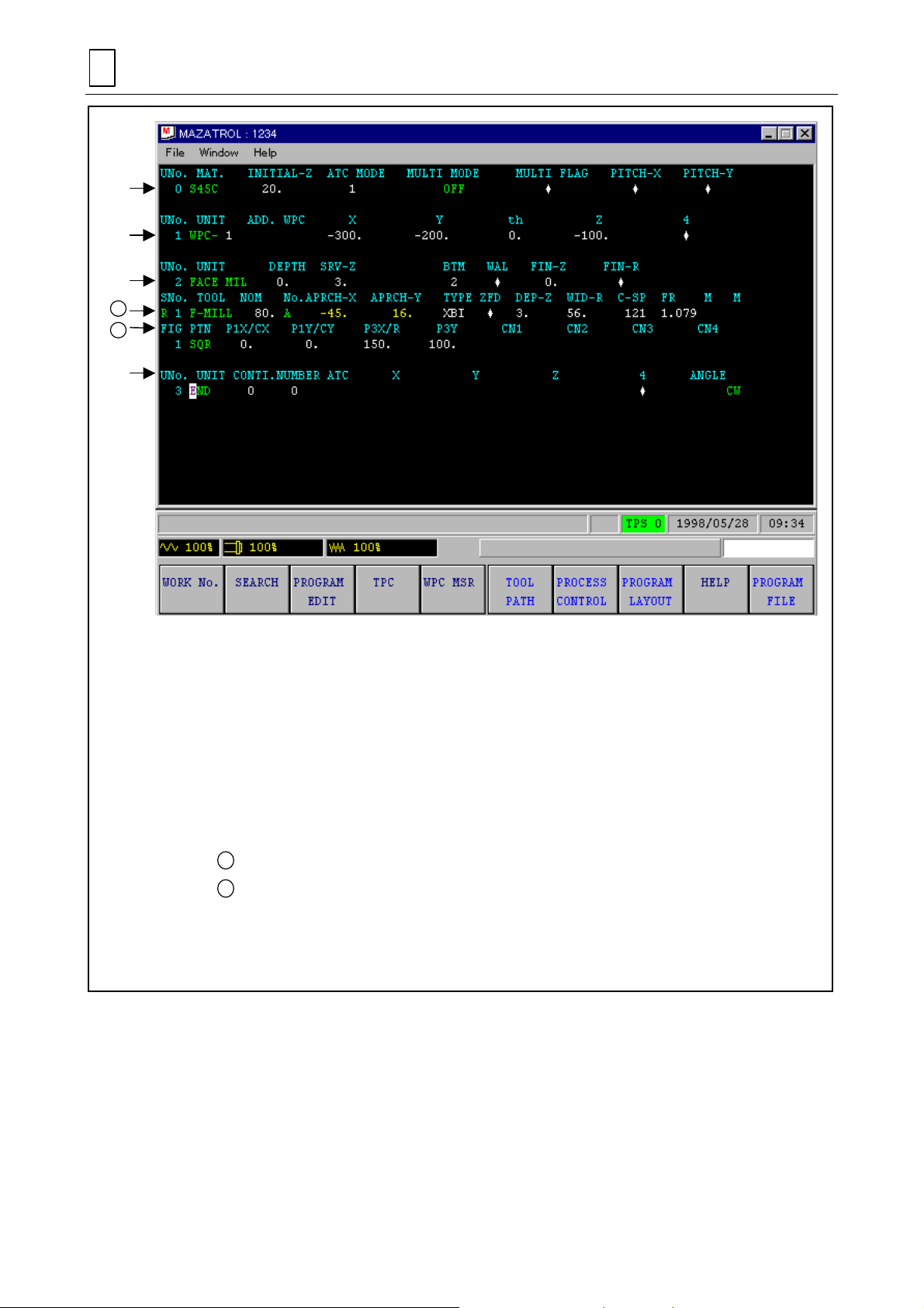
4-4-1 Program structure
The structure of MAZATROL program is described before creating a program. Each MAZATROL
program consists of units. Conversely, a combination of program units forms a program. The
name of each part of a program is described below using part of the program to be created.
D735P0006E
4-9
Page 40
4
A
B
A
B
PROCEDURE BEFORE PERFORMING THE MACHINI NG
[1]
[2]
[3]
[4]
D735P0007E
[1] Common unit
Basic data rel a ted to the en tire prog ra m, su c h as the ma teria l of th e workpiece, is to be
input to this unit.
[2] Basic coordinates system unit
The coordi nat e values of the workpi ece zero poin t in the mach ine coo rdin ates s ystem
are to be input to this unit.
[3] Machining units
Various types of machining units are provided. Data related to selection of a machining
method an d to machining di m e ns ions are to be input to these units.
Tool sequence ................consists of data inputs related to the operation of a tool.
Shape sequence............. consists of data inputs related to the machining shape on
a drawing.
[4] End unit
Denotes the end of a program (i.e., the completion of machining).
Fig. 4-5 Program structure
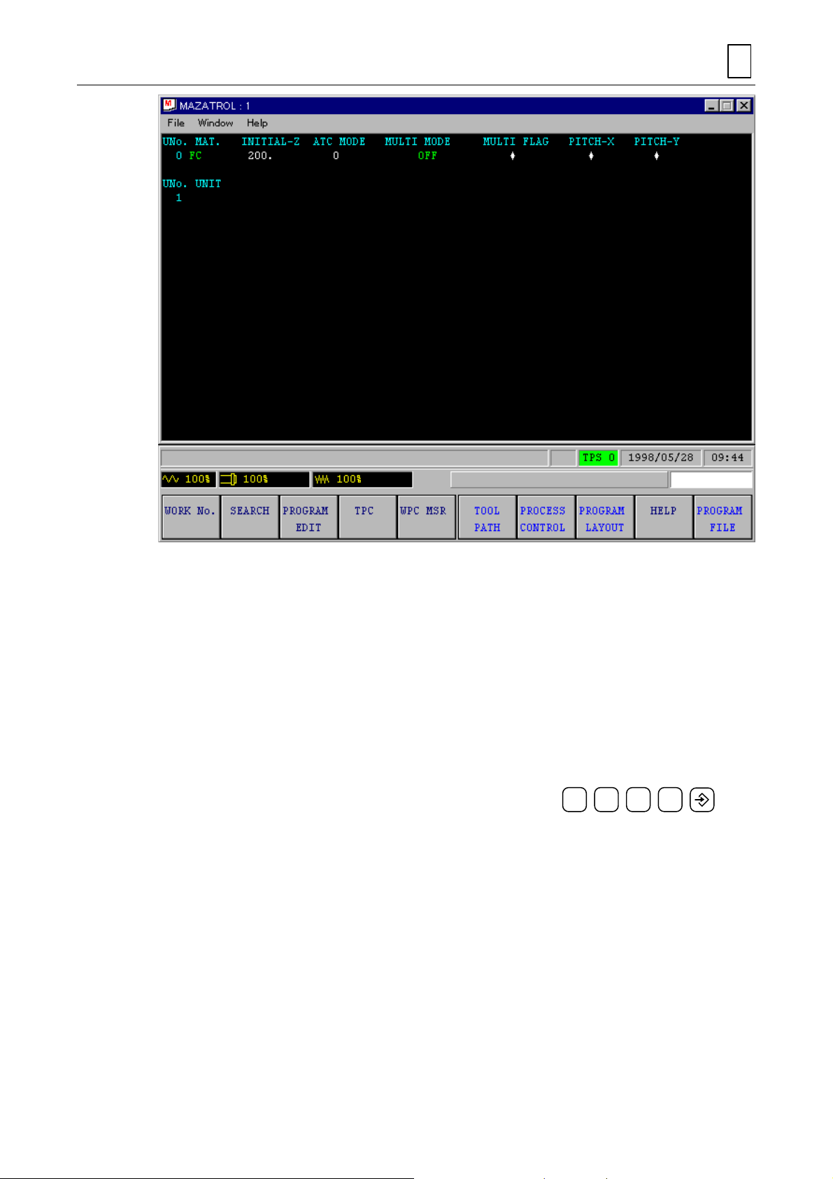
4-4-2 Calling up the PROGRAM display
First, the
FILE
display:
PROGRAM
display is to be presented as previously done when displaying the
TOOL
(1) Press the display selector key.
(2) Press the menu key
!
The
PROGRAM
PROGRAM
.
display will be presented then as shown belo w.
4-10
Page 41
PROCEDURE BEFORE PERFORMING THE MACHI NING
4
Note:
The above display status is referred to as the listing mode.
The listing mode is a program-contents check mode.
For details, see Part 2, Section 1-1, “Listing Mode and Creating Mode.”
4-4-3 Assigning workpiece numbers
Number the individual pro grams to be created. T hese numbers identif y the individua l programs
just as part number in a part drawing identif ies the indi vidual parts . These num bers are r eferred
to as workpiece num bers , and the desired number f r om 1 to 9999 999 9 c an be se lec ted for each
program. Here, workpiece No. 1234 is to be set.
(1) Press the menu key
WORK No.
(2)
!
The message
If either one of the t wo displays [1] and [2] sho wn below is displayed inste ad of this
message, then this indicat es that workpiece No. 1 234 has already been used. In that
case, input a different workpiece number.
............................................................................
WORK No.
NEW PROGRAM <MENU>?
1 2 3 4
will be displayed.
D735P0008E
4-11
Page 42

4
PROCEDURE BEFORE PERFORMING THE MACHINI NG
[1] MAZATROL program
[2] EIA/ISO program
D735P0009E
4-12
D735P0010E
Page 43

PROCEDURE BEFORE PERFORMING THE MACHI NING
4
Note:
In M640M, two different programs can be created. The program [1] above is referred to
as a MAZATROL program, and the one [2], as an EIA/ISO program.
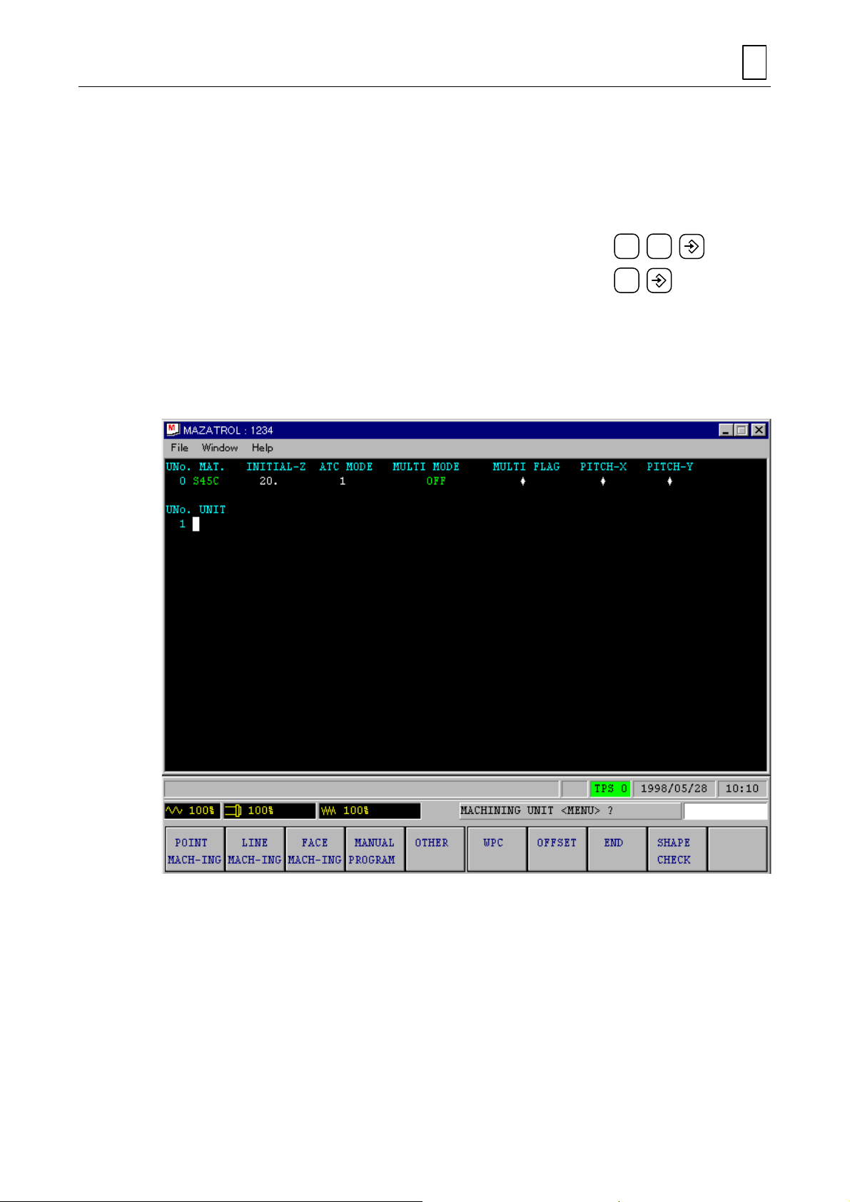
4-4-4 Creating a program
Let us create a program.
(1) After setting the workpiece number, press the menu key
!
The display shown in Figure 4-6 will be presented. T he program creation will become
possible. This status is referred to as the creating mode.
If the EIA/ISO prog ramming function (optio n) is provided in the s ystem, the following
menu will be displayed.
WORK No. EIA/ISO
PROGRAM
(2) The following display will be presented. The program creation will become possible.
MAZATROL
PROGRAM
MAZATROL PROGRAM
.
Fig. 4-6 PROGRAM display (edit mode)
4-4-5 Creation of common unit
The common unit is the program unit that must be created a t the head position of a pr ogram.
Basic data on the entire program is to be input to this unit.
The help window is described here before the creation of comm on unit. Prior t o input of data to
the unit, full details of the data to inp ut c an be dis p layed on the screen for ease of pr ogramming.
This display is referred to as the help window display. Carry out the following operation to display
the help window display:
D735P0011E
4-13
Page 44

4
p
PROCEDURE BEFORE PERFORMING THE MACHINI NG
(1) Press the menu key
HELP
.
The following help window display will be presented.
D735P0012E
Now, start creating the common unit. The data for the article MAT, INITIAL-Z and ATC
MODE will be specified here.
MAT Specify the material of the workpiece.
INITIAL-Z Specify the initial he ight of the t oo l where it c om es close to th e work piece
for machining purposes (see figure below).
From this level up, the t ool
is kept clear of the workpiec e
or jigs.
Initial point
Workpiece
oint
zero
M3P018
Fig. 4-7 Tool path
4-14
Page 45
PROCEDURE BEFORE PERFORMING THE MACHI NING
ATC MODE Specify the manner in whic h the too l is to be returned to the ATC pos iti on
for tool change.
MULTI MODE Use this function when m ore than one work piece of the sam e type are to
be arranged on the table for successive machining. Do not use this
function here.
4
MATEIRAL <MENU>?
(2)
INITIAL POINT Z (CLEARANCE)?
(3)
ZERO RETURN <Z. X+Y: 0, X+Y+Z: 1>?
(4)
MULTI MODE <MENU>?
(5)
The common unit will be created as shown below.
When the unit is created, the help windo w will be closed and the program wil l a wait dat a i nput to
the next unit.
...................................................................
................................................
.....................................
...............................................................
S45C
2 0
1
MULTI OFF
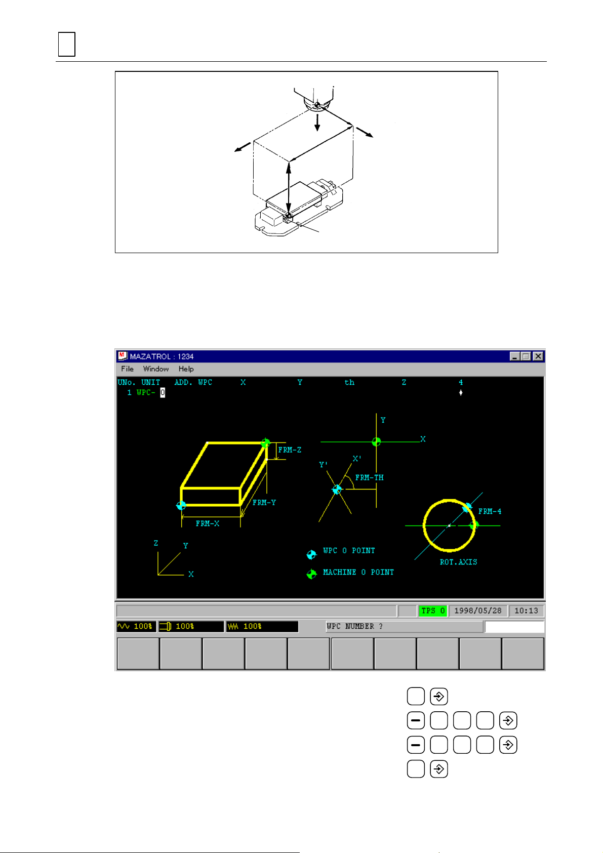
4-4-6 Creation of basic coordinates system unit
Let us set the basic coordinates (the coordinate values of the workpiece zero point in the
machine coordinate s ystem). This data is to be input using the coor dinates measuring func iton
(refer to Part 2) af ter workpiec e has been m ounted on th e machine. Her e, inpu t the data o n the
assumption that workpiece has been mounted in the position shown below.
4-15
D735P0013E
Page 46
4
)
)
–
PROCEDURE BEFORE PERFORMING THE MACHINI NG
Machine zero point
–200 (Basic coordinate y)
–X
(Basic
coordinate z
Fig. 4-8 Workpiece mounting position
(1) While the message
(2) Press the menu key
!
The following help window will be presented. “WPC” is the abbreviation of the
workpiece coordinates.
–Z
–300
100
(Basic
coordinate x
Workpiece zero point
MACHINING UNIT <MENU>?
HELP
.
–Y
NM210-00526
is displayed, press the menu key
WPC
.
D735P0014E
WPC NUMBER?
(3)
WORKPIECE COORDINATE, WPC-X?
(4)
WORKPIECE COORDINATE, WPC-Y?
(5)
WORKPIECE COORDINATE, WPC-th?
(6)
................................................................... 1
.............................. 3
..............................
............................. 0
0 0
2 0 0
4-16
Page 47
PROCEDURE BEFORE PERFORMING THE MACHI NING
4
WORKPIECE COORDINATE, WPC-Z?
(7)
WORKPIECE COORDINATE, WPC-4?
(8)
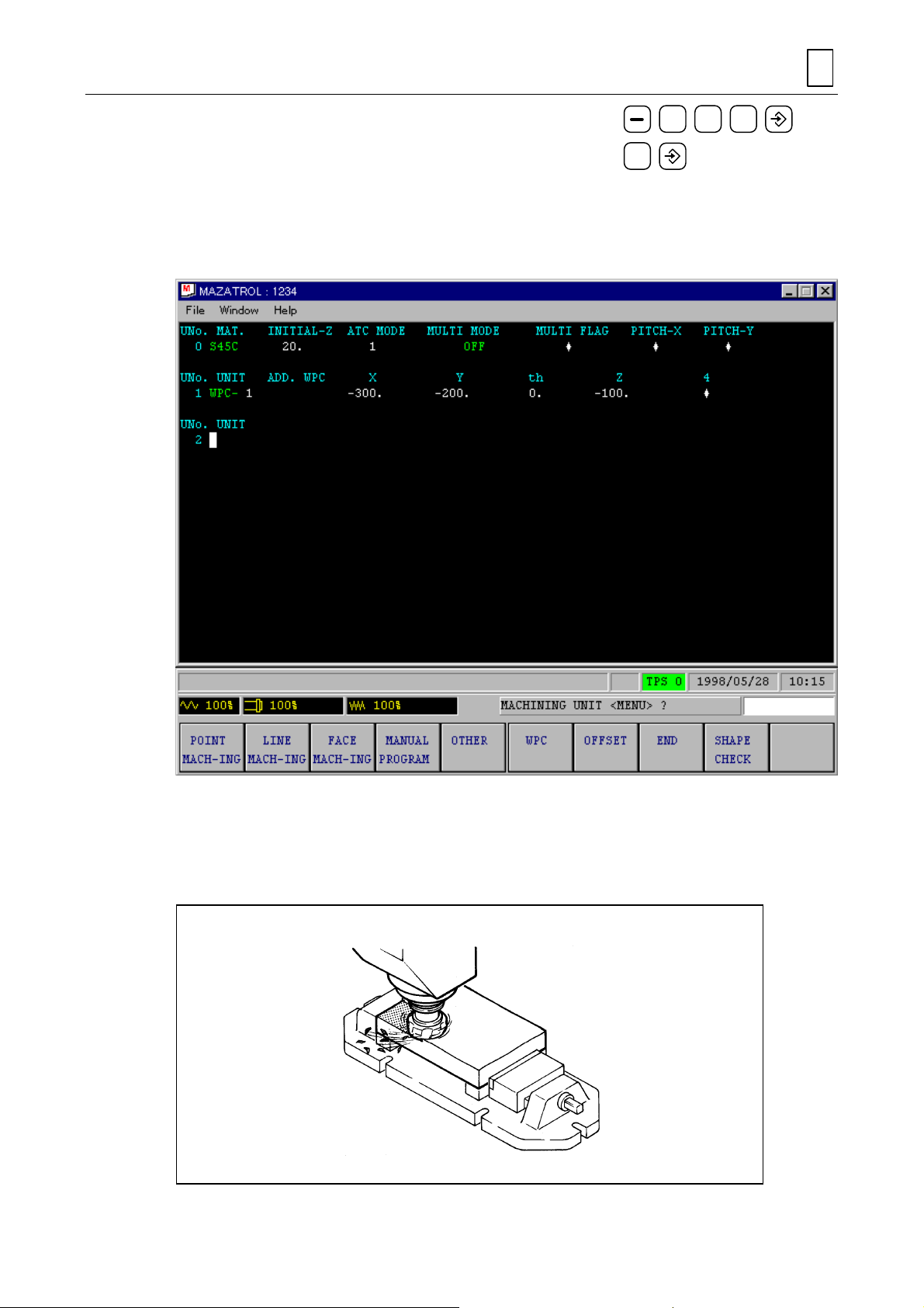
The basic coordinates system unit will be created as shown below.
When the unit is created, the help windo w will be closed and the program wil l a wait dat a i nput to
the next unit.
..............................
...............................
0
1 0 0
4-4-7 Face machining unit
Let us program a unit that mills the top face of a particular material. This machining unit is
referred to as a face milling unit.
D735P0015E
NM210-00517
4-17
Page 48
4
PROCEDURE BEFORE PERFORMING THE MACHINI NG
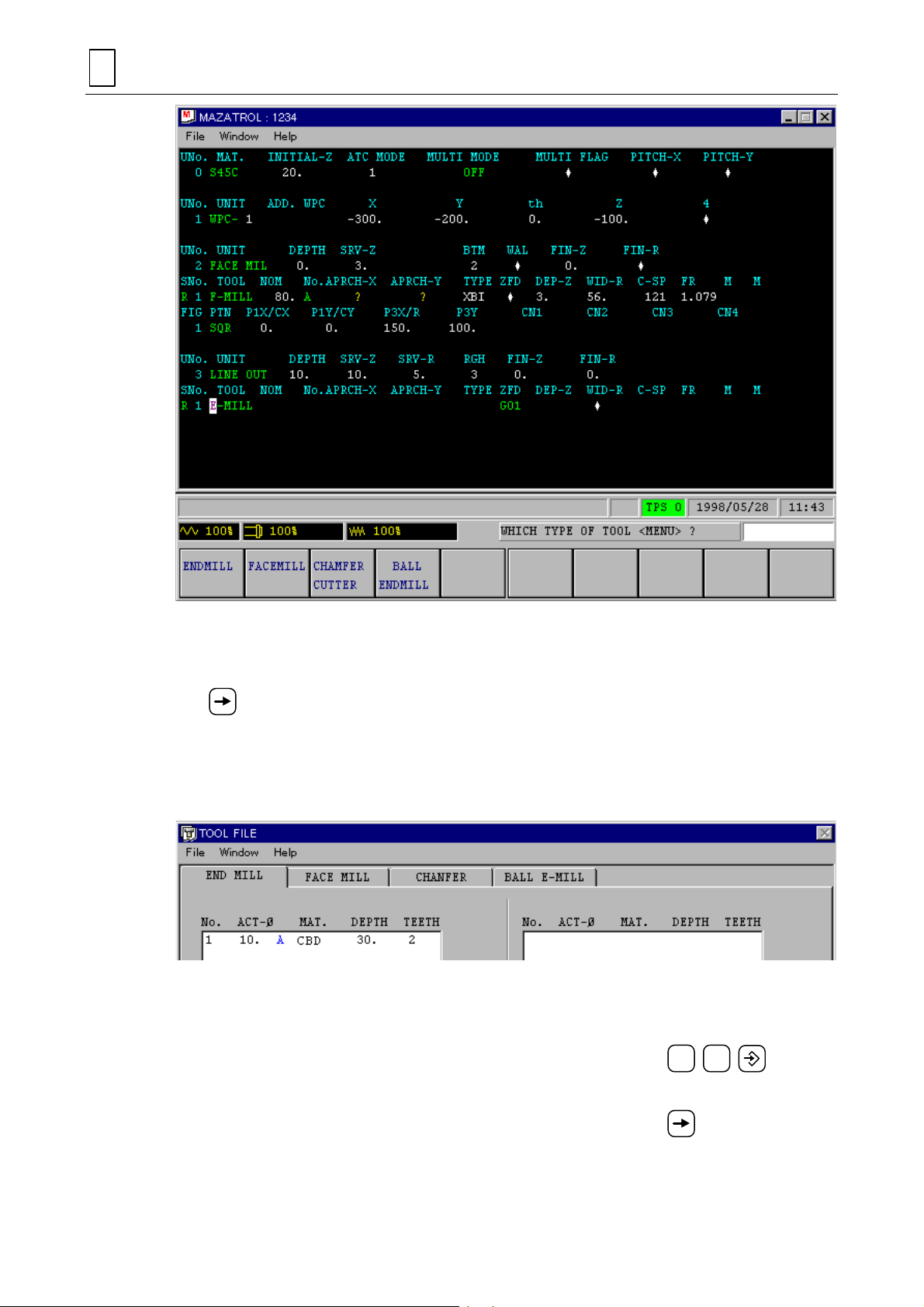
1. Creation of face machining unit
(1) W hile the m ess age
MACH-ING .
MACHINING UNIT <MENU>?
(2)
(3) Press the menu key
!
The following help window is presented.
MACHINING UNIT <MENU>?
........................................................
HELP
.
is displayed, pr ess the m enu key
FACE MIL
FACE
D735P0016E
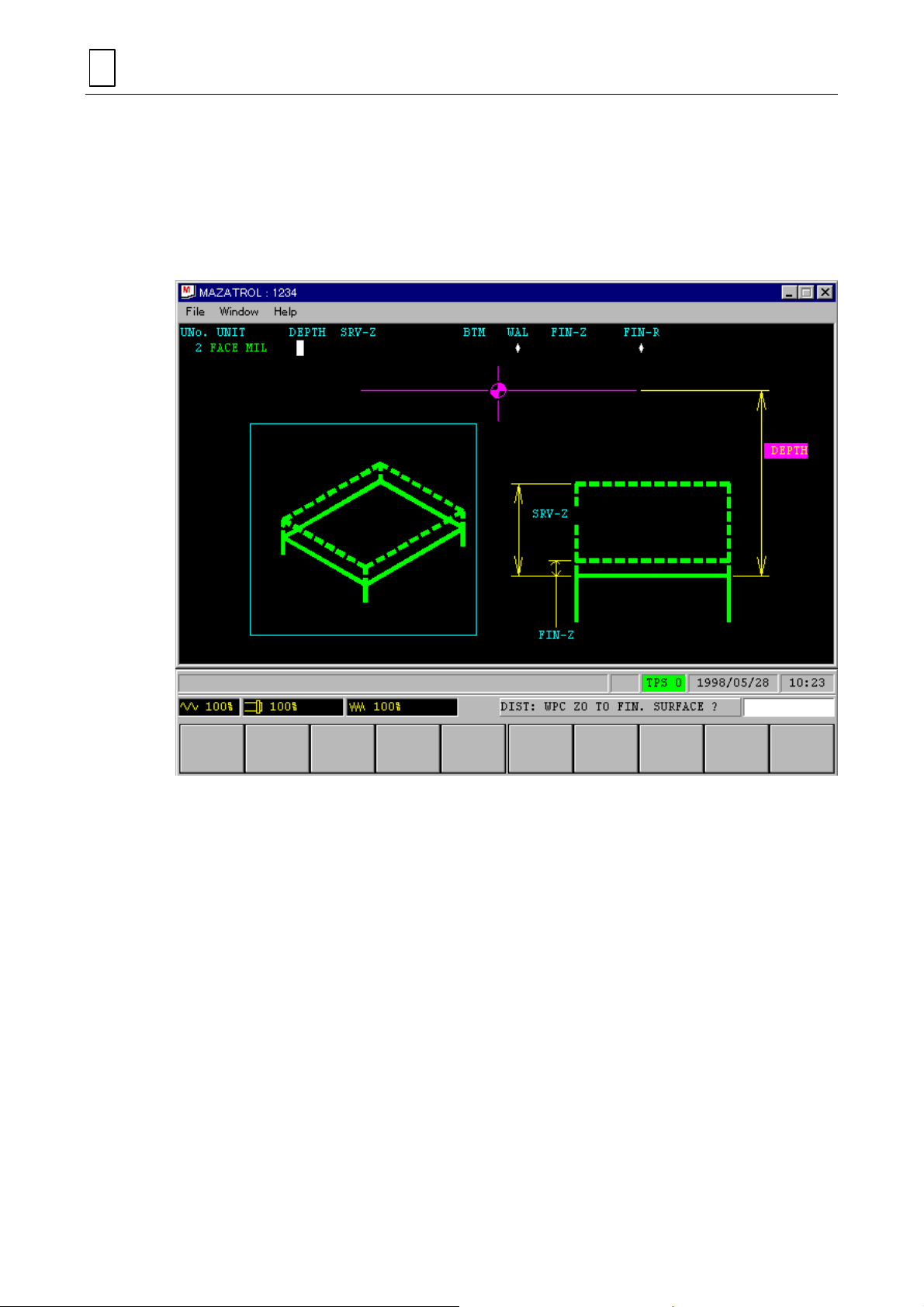
Now, start creating the fac e machining unit. T he data for the article DEPT H, SRV-Z, BT M,
and FIN-Z will be specified here.
DEPTH ..........Input the distance from the workpiece zero point of the Z axis to the surface to
be finished.
Here, the depth is 0 because the workpiece zero point is on the finishing
surface.
4-18
Page 49

PROCEDURE BEFORE PERFORMING THE MACHI NING
+Z
Workpiece zero point
+XPosition of
WPC-Z = 0
Fig. 4-9 DEPTH and SRV-Z
Chamfering area
Allowance Z
(SRV-Z)
Surface to be
finished
M3P023
SRV-Z .............Input the chamfer ing thick ness of the work piece. An appr oxim ate value ma y
be input because the workpiece surface is not plane.
BTM.................Input an appropriate finishing code that designates the roughness of the
workpiece surface to be finished.
FIN-Z ...............Input the finish milling thickness. This data will be automatically set if the
roughness of the bottom is specified using a finishing code of the menu.
DIST: WPC Z0 TO FIN. SURFACE?
(4)
.............................................
0
4
Z AXIS STOCK REMOVAL?
(5)
BOTTOM FACE ROUGHNESS <MENU>?
(6)
FINISH ALLOWANCE Z?
(7)
.........................................................
..............................................................
...................................
3
!
2
(When the bottom roughness is input, the FIN-Z value will be set automatically. Thus , the
operator can proceed directly to the next data item using the appropriate cursor key.)
A machining unit such as that s ho wn belo w is n o w com p leted . Us ua lly, a tool appropriate f or the
particular tool sequenc e is autom atic ally s elected on t he basis of the data of the m achini ng uni t.
Here, a face mill has been selected.
4-19
Page 50

4
PROCEDURE BEFORE PERFORMING THE MACHINI NG
2. Creation of tool sequence
(1) W hile the mes sage
.
(2) Pr ess the menu ke y
that the previously registered tool is included in the display.
!
The following
mill is registered.
TOOL FILE (FACEMILL)
WHICH TYPE OF TOOL <MENU>?
TOOL FILE
to call the
TOOL FILE
display shows that the 80 mm diameter face
D735P0017E
is displayed, press the curs or key
display on the screen, a nd check
4-20
Page 51

PROCEDURE BEFORE PERFORMING THE MACHI NING
4
(3) Press the menu key
programming.
NOMINAL DIAMETER?
(4)
TOOL FILE CODE
(5)
MACHINING PRIORITY No.?
(6)
(Skip to the next item s inc e the id ent ic al-tool priority function is n o t use d h er e. R efer to Part
2, Chapter 5.)
APPROACH POINT X, AUTO
(7)
APPROACH POINT Y, AUTO
(8)
CUTTING DIRECTION <MENU>?
(9)
The possible directions of cutting are shown below.
PROGRAM
.................................................................
?........................................................................
to return to the
........................................................
<MENU>?
→→→→
<MENU>?
→→→→
.................................................
.................................
.................................
PROGRAM
A
AUTO SET
AUTO SET
X BI-DIR
display and continue
8 0
D735P0018E
4-21
Page 52

4
PROCEDURE BEFORE PERFORMING THE MACHINI NG
Cutting feed
Rapid feed
<BI-DIR>
<BI-DIR SHORT>
DEPTH OF CUT?
(10)
WIDTH OF CUT?
(11)
CUTTING SPEED, AUTO
(12)
FEEDRATE, AUTO
(13)
(14)
(15)
M CODE?
M CODE?
.......................................................................
.......................................................................................
<BI-DIRARCSHORT>
...........................................................................
...........................................................................
<MENU>?
→→→→
<MENU>?
→→→→
<UNI-DIR>
........................................
..................................................
M3P026
AUTO SET
AUTO SET
AUTO SET
AUTO SET
A tool sequence such as that s hown below is now completed. F or most of the data items, the
optimal data is set b y depressing the m enu key
AUTO S ET
. The data of the artic le APRCH-X,
APRCH-Y, however, m aintains ? since the necessary dat a is autom atically set u pon com pletion
of the tool path check.
4-22
D735P0019E
Page 53

PROCEDURE BEFORE PERFORMING THE MACHI NING
3. Cutting parameters
The cutting parameters that have been automatically set in procedural step (12) and (13) of
creation of tool sequence above are described here.
The speed at wh ich a too l revolves (circ umfer ential speed) a nd the rat e at which the tool is fed
(feed rate) are referred to as cutting parameters.
Circumferential speed (C-SP):
Speed (m/min) at whic h a tool m oves on th e outer circ umf erence. T he relations hip betwee n the
revolutions per minute and circumferential speed is given by the following equation.
4
Circumferential
speed (m/min)
Feedrate (FR):
The distance (mm /rev) through which workpiece is cut during one revolution of the tool. This
feedrate is called synchronous feedrate.
4. Creation of shape sequence
Tool diameter (mm) × Revolutions per minute (rpm) × 3.14
=
1000
Circumferential speed
Feedrate
NM210-00527
Next, let us program a shape sequence.
Read the machining area from the drawing, and input the coordinate values necessary for the
machining shape. For face milling, the top face of workpiece is to be machined.
Thus, input the dimensions of a shape such as that shown below.
4-23
Page 54

4
g
)
PROCEDURE BEFORE PERFORMING THE MACHINI NG
100
(Y coordinate of
onal point
dia
Start point
150 (X coordinate of diagonal point)
Diagonal point
Corner 2 Corner 3
Corner 1 Corner 4
M3P028
Note:
(1)
(2)
(3)
(4)
(5)
(6)
(7)
The X- and Y-coordinates of the start point are those of the workpiece zero point.
PATTERN OF FIGURE <MENU>?
CORNER 1 COORDINATE X?
CORNER 1 COORDINATE Y?
CORNER 3 COORDINATE X?
CORNER 3 COORDINATE Y?
CORNER 1 CHAMFER?
......................................................
PATTERN OF FIGURE <MENU>?
......................................
............................................
............................................ 0
............................................ 1
............................................ 1
......................................
A shape sequence such as that shown below is now completed.
SQUARE
0
5 0
0 0
SHAPE END
D735P0020E
4-24
Page 55
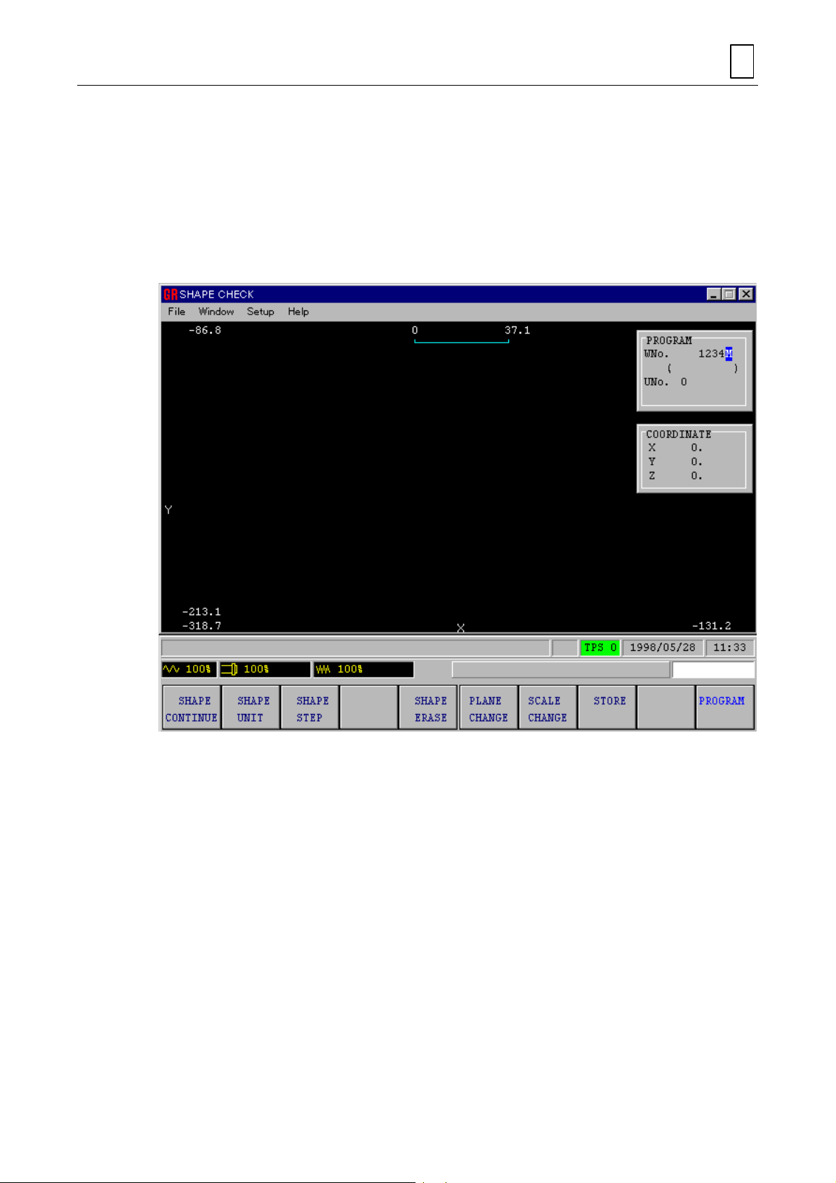
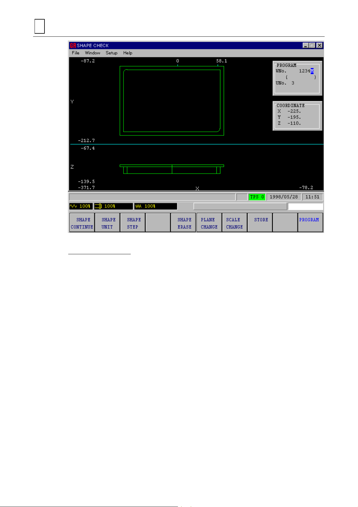
5. Shape check
PROCEDURE BEFORE PERFORMING THE MACHI NING
4
Check the
Of the varioius functions available with the
display of shapes, for erasure of shapes, and for step display of shapes are described here. See
Section 6-3, “SHAPE CHECK Display” of the Operating Manual for details of other functions.
(1) Press the menu key
SHAPE CHECK
!
The following
display to ensure that no errors are included in the inp ut data.
SHAPE CHECK
SHAPE CHECK
SHAPE CHECK
.
display will be displa yed.
display, onl y those for continuous
(2) Press the menu key
!
Shapes will be displayed continuously. The shapes displayed on the screen will be
those of the portions which are chamfered by machining.
SHAPE CONTINUE
4-25
D735P0021E
to display shapes continuously.
Page 56

4
PROCEDURE BEFORE PERFORMING THE MACHINI NG
(3) Press the menu key
(4) Repe ated ly press the menu key
the screen.
!
The reverse display state of the menu will be cleared when the final group of shapes is
displayed.
SHAPE ERASE
to erase the shape.
SHAPE STEP
D735P0022E
several times to call shapes step by step on
4-26
Page 57

PROCEDURE BEFORE PERFORMING THE MACHI NING
4
(5) Press the menu key
This completes a face milling unit for use in face machining.
4-4-8 Line machining unit
Let us create a unit that steps the edges of a material by contour machining. This machining unit
is referred to as an outside linear machining.
PROGRAM
to resume the
PROGRAM
D735P0023E
display.
1. Creation of line machining unit
(1) W hile the mess age
MACH-ING
.
MACHINING UNIT <MENU>?
4-27
NM210-00518
is displayed, pr ess the menu key
LINE
Page 58

4
PROCEDURE BEFORE PERFORMING THE MACHINI NG
MACHINING UNIT <MENU>?
(2)
(3) Press the menu key
!
The help window will be presented.
HELP
........................................................
.
LINE OUT
D735P0024E
Now, start creating the l ine m achining un it. T he data for the artic le D EPT H, SRV-Z, SR V-R
and RGH will be specified here.
DEPTH............... Input a depth value of 10.
SRV-Z ................Input the wall thickness of the workpiece through which it is to be
chamfered in the Z ax ial direct ion f rom the f ace m ille d surf ace (s ee f igure
below).
SRV-R................ Input the wall thickness of the workpiece through which it is to be
chamfered in the radial direction (see figure below).
4-28
Page 59

z
(
)
A
)
Depth =
Allowance Z
SRV-Z
Fig. 4-10 SRV-Z and SRV-R
PROCEDURE BEFORE PERFORMING THE MACHI NING
x
y
llowance R (SRV-R
M3P034
4
DIST: WPC Z0 TO FIN. SURFACE?
(4)
Z AXIS STOCK REMOVAL?
(5)
X/Y AXIS STOCK REMOVAL?
(6)
.............................................
.........................................................
......................................................
1 0
1 0
5
""
SURFACE ROUGHNESS <MENU>?
(7)
FINISH ALLOWANCE Z?
(8)
FINISH ALLOWANCE R?
(9)
............................................
..............................................................
..............................................................
3
A line machining unit s uch as that shown below is no w completed. This displ ay shows that an
end mill has been automatically selected for the particular tool sequence that is to be
programmed.
4-29
Page 60
4
PROCEDURE BEFORE PERFORMING THE MACHINI NG
2. Creation of tool sequence
(1) W hile the mes sage
.
(2) Pr ess the menu ke y
that the previously registered tools ar e inclu ded in the dis play.
!
The following
is registered.
(3) Press the menu key
programming.
NOMINAL DIAMETER?
(4)
TOOL FILE (ENDMILL)
WHICH TYPE OF TOOL <MENU>?
TOOL FILE
PROGRAM
.................................................................
to call the
to return to the
TOOL FILE
display shows that the 10-m m diameter end mill
D735P0025E
is displayed, press the curs or key
display on the screen, a nd check
D735P0026E
PROGRAM
display and continue
1 0
TOOL FILE CODE <MENU>?
(5)
MACHINING PRIORITY No.?
(6)
(Skip to the next article since the priority funct ion for the same tool is not to be used here.
See Part 2, Chapter 5.)
........................................................
........................................................
4-30
A
Page 61
PROCEDURE BEFORE PERFORMING THE MACHI NING
4
APPROACH POINT X, AUTO
(7)
[APPROACH POINT Y, AUTO
(8)
CUTTING DIRECTION <MENU>?
(9)
(Specify the directi on in which the circumf erence is to be cut. The possible d irections of
cutting are clockwise (CW) and counterclockwise (CCW).)
CW
FEEDRATE Z, <MENU>/DATA <INPUT>?
(10)
DEPTH OF CUT?
(11)
...........................................................................
<MENU>?
→→→→
<MENU>?
→→→→
.......................................
..........................
...............................
CCW
...................................
AUTO SET
AUTO SET
CW CUT
NM210-00528
AUTO SET
CUTTING SPEED, AUTO
(12)
FEED RATE, AUTO
(13)
M CODE?
(14)
M CODE?
(15)
A tool sequence such as that shown below is now completed.
.......................................................................................
.......................................................................................
→→→→
<MENU>?
→→→→
<MENU>?
........................................
.................................................
AUTO SET
AUTO SET
4-31
Page 62

4
g
)
PROCEDURE BEFORE PERFORMING THE MACHINI NG
3. Creation of shape sequence
Next, let us program a s hape sequence. For outside linear machining, the edges of a material
are to be machined. Set the dimensions of a shape such as that shown below.
145 (X coordinate of diagonal point)
Corner 2
95
(Y coordinate of
onal point
dia
(Y coordinate
of the start
point)
5
(1) W hile the message
SQUARE
.
R5
Corner 1
5 (X coordinate of the start point)
PATTERN OF FIGURE <MENU>?
Corner 3
R5
Corner 4
M3P037
is displayed, press th e menu key
D735P0027E
CORNER 1 COORDINATE X?
(2)
CORNER 1 COORDINATE Y?
(3)
CORNER 3 COORDINATE X?
(4)
......................................................
......................................................
......................................................
5
5
1 4 5
4-32
Page 63

PROCEDURE BEFORE PERFORMING THE MACHI NING
4
CORNER 3 COORDINATE Y?
(5)
CORNER 1 CHAMFER?
(6)
CORNER 2 CHAMFER?
(7)
CORNER 3 CHAMFER?
(8)
CORNER 4 CHAMFER?
(9)
PATTERN OF FIGURE <MENU>?
(10)
A shape sequence such as that shown below is now completed.
......................................................
................................................................
................................................................
................................................................
................................................................
................................................
9 5
5
5
SHAPE END
4. Shape check
Here, let us call the
(1) Press the menu key
(2) Press the menu key
SHAPE CHECK
SHAPE CHECK
SHAPE CONTINUE
display on the screen.
to call the
.
4-33
SHAPE CHECK
D735P0028E
display.
Page 64

4
PROCEDURE BEFORE PERFORMING THE MACHINI NG
D735P0029E
The PLANE CHANGE f unciton is desc ribe d here. The s hape be ing d ispla yed in pr oce dura l step
(2) is that of the workpiece as seen from above. With this function, it becomes possible to display
shapes as seen from the side or from an oblique angle.
The selectable pla ne is one of the f our types sho wn below. It is also possib le to display one of
two plane pairs (either XY-XZ (XY plane and XZ plane) or XY-YZ (XY plane and YZ plane)) at the
same time. See Section 6-3, “SHAPE CHECK Display” of the Operating Manual for the details.
4-34
Page 65

XZ plane
PROCEDURE BEFORE PERFORMING THE MACHI NING
Stereographic
view
XY plane
YZ plane
4
Fig. 4-11 Plane selection
Let us now display shapes of various planes.
XY-XZ plane
(3) Press the menu key
(4) Press the menu key
!
Shapes as seen from above and from the side are selected.
(5) Press the menu key
!
As shown below, a shape as seen from above ( XY plane) a nd a shape as s een from
PLANE CHANGE
XY-XZ
.
SHAPE CONTINUE
the side (XZ plane) are displayed at the same time.
M3P040
.
to display shapes continuously.
4-35
Page 66
4
PROCEDURE BEFORE PERFORMING THE MACHINI NG
Three-dimens ional pla n
(6) Press the menu key
(7) Press the menu key
!
A shape as seen obliquely from above is selected.
(8) Press the menu key
!
The shape will be displayed in stereographic form as shown below.
PLANE CHANGE
3-D
.
SHAPE CONTINUE
.
D735P0030E
to display shapes continuously.
4-36
Page 67

PROCEDURE BEFORE PERFORMING THE MACHI NING
4
(9) Press the menu key
(10) Press the menu key XY to change the display to that of XY plan.
Note:
(11) Press the menu key
This completes an outside linear machining unit.
The selected plane maintains its shape until another plane has been selected.
4-4-9 Point machining unit (1)
Let us create a program unit that is us e d to dr ill a 10- mm diameter through-ho le. This machining
unit is referred to as a drilling unit.
PLANE CHANGE
PROGRAM
. The
.
PROGRAM
D735P0031E
display is resumed.
4-37
NM210-00519
Page 68

4
PROCEDURE BEFORE PERFORMING THE MACHINI NG
1. Creation of point machining unit (1)
(1) W hile message
MACH-ING
MACHINING UNIT <MENU>?
(2)
(3) Press the menu key
!
The following help window will be presented.
MACHINING UNIT <MENU>?
.
HELP
is displayed, press the menu key
........................................................
.
POINT
DRILLING
D735P0032E
Now, start creating the point m achining unit. The d ata for the item DIA, DEPTH and CHMF will
be specified here.
HOLE DIAMETER?
(4)
HOLE DEPTH?
(5)
CHAMFER WIDTH?
(6)
A machining program unit such as that shown b elow is now com pleted. This shows t hat a spot
and a drill have been automatically selected for the tool sequence that is to be programmed.
........................................................................
...............................................................................
.......................................................................
1 0
2 0
0
4-38
Page 69

PROCEDURE BEFORE PERFORMING THE MACHI NING
4
2. Creation of tool sequence
For the point m achining unit, it is necessar y just to set the c utting parameters (c ircumferential
speed and feedrate) since most of the tool sequence data are set automatically.
(1) While the message
position under the article C-SP by pressing the cursor key
CUTTING SPEED, AUTO
(2)
FEEDRATE, AUTO
(3)
M CODE?
(4)
M CODE?
(5)
(6) Press the cursor key
the article C-SP.
CUTTING SPEED, AUTO
(7)
FEEDRATE, AUTO
(8)
M CODE?
(9)
.......................................................................................
.......................................................................................
.......................................................................................
WHICH TYPE OF TOOL <MENU>?
<MENU>?
→→→→
<MENU>?
→→→→
eight times in succession to move the cursor to the position under
<MENU>?
→→→→
<MENU>?
→→→→
........................................
..................................................
........................................
..................................................
is displayed, move the cursor to the
six times in successi on.
HSS AUTO
HSS AUTO
HSS AUTO
HSS AUTO
D735P0033E
M CODE?
(10)
A tool sequence such as that shown below is now completed.
.......................................................................................
4-39
Page 70

4
)
PROCEDURE BEFORE PERFORMING THE MACHINI NG
3. Creation of shape sequence
Next, create a shape s equence. For drillin g, input the coord inates of the ho le center as sho wn
below.
(Y coordinate of
hole center
(1) W hile the mes sage
POINT
key
20
100
(X coordinate of hol e ce nter)
M3P046
POINT CUTTING PATTERN <MENU>?
is displayed, press the menu
.
D735P0034E
Z VALUE OF WORK SURFACE?
(2)
HOLE POSITION X?
(3)
HOLE POSITION Y?
(4)
......................................................................
......................................................................
.................................................
0
1 0 0
2 0
4-40
Page 71

PROCEDURE BEFORE PERFORMING THE MACHI NING
y
g
g
4
PATH <XY:0, Y
(5)
(The tool path to the next hole is to be selected from the three types shown below. If,
however, the hole to which the tool is to be fed does not exis t, input 0 since the selected
function is unavailab le.)
y
x
If 0, both the X and Y axes
move simultaneousl
Fig. 4-12 Tool path
OMIT SPT MACHINING <Y:1, N:0>?
(6)
.
→→→→
X:1, X
Y:2>?
→→→→
If 1, the X axis starts moving
after the Y axis has moved.
...................................................
y
x
............................................
0
y
x
If 2, the Y axis starts moving
after the X axis has moved.
0
M3P047
(If 0, drilling occurs. If 1, positioning only occurs.)
RETURN POSITION <INIT:0, R:1>?
(7)
The height of the tool path to the next hole is to be selected from the two types shown below.
(If however, the hole to wh ich the t ool is to be fed does not ex ist, inpu t 0 since th e sel ected
function is unavailab le.)
[1]
[6]
Initial point
[5]
[2]
R point
[3] [4]
If 0, the tool moves to the next hole
at the hei
ht of initial point.
Fig. 4-13 Return position
.............................................
[1]
[2]
Initial point
[5]
[3]
[4]
Cutting
Positionin
If 1, the tool moves to the next hole
at the hei
0
R point
ht of R point.
M3P048
POINT CUTTING PATTERN <MENU>?
(8)
........................................
SHAPE END
A shape sequence such as that shown below is now completed.
4-41
Page 72

4
PROCEDURE BEFORE PERFORMING THE MACHINI NG
4. Shape check
Let us call the
(1) Press the menu key
(2) Press the menu key
SHAPE CHECK
SHAPE CHECK
SHAPE CONTINUE
display on the screen to check the shapes.
to call the
.
SHAPE CHECK
display.
D735P0035E
4-42
Page 73

PROCEDURE BEFORE PERFORMING THE MACHI NING
4
D735P0036E
The SCALE CHANG E func tion is ex plained h ere. T his func tion a llows en largem ent/reductio n of
shapes, as well as changing of the shape display position.
Enlargement of shapes
Let us display a 10 mm diameter hole in enlarged form using the SCALE CHANGE function.
(3) Press the menu key
(4) Us ing the curs or keys
shown below.
SCALE CHANGE
, place the cursor on th e 10 mm diameter hole position as
.
4-43
Page 74

4
PROCEDURE BEFORE PERFORMING THE MACHINI NG
SCALE <INPUT>?
(5)
(The size of the shap e is changed so that the line in the center on the top of the scr een
becomes 20 mm in length.)
(6) Press the menu key
!
As shown below, the s hape has been en larged with its c enter in the 10 mm diam eter
hole position.
..........................................................................
SHAPE CONTINUE
.
2 0
D735P0037E
4-44
Page 75

PROCEDURE BEFORE PERFORMING THE MACHI NING
4
Reduction of shapes
(7) Press the menu key
SCALE <INPUT>?
(8)
(The size of the shap e is changed so that the line in the center on the top of the scr een
becomes 100 mm in length.)
(9) Press the menu key
!
As shown below, the shape has been reduced in size.
SCALE CHANGE
..........................................................................
SHAPE CONTINUE
.
.
1 0 0
D735P0038E
4-45
Page 76
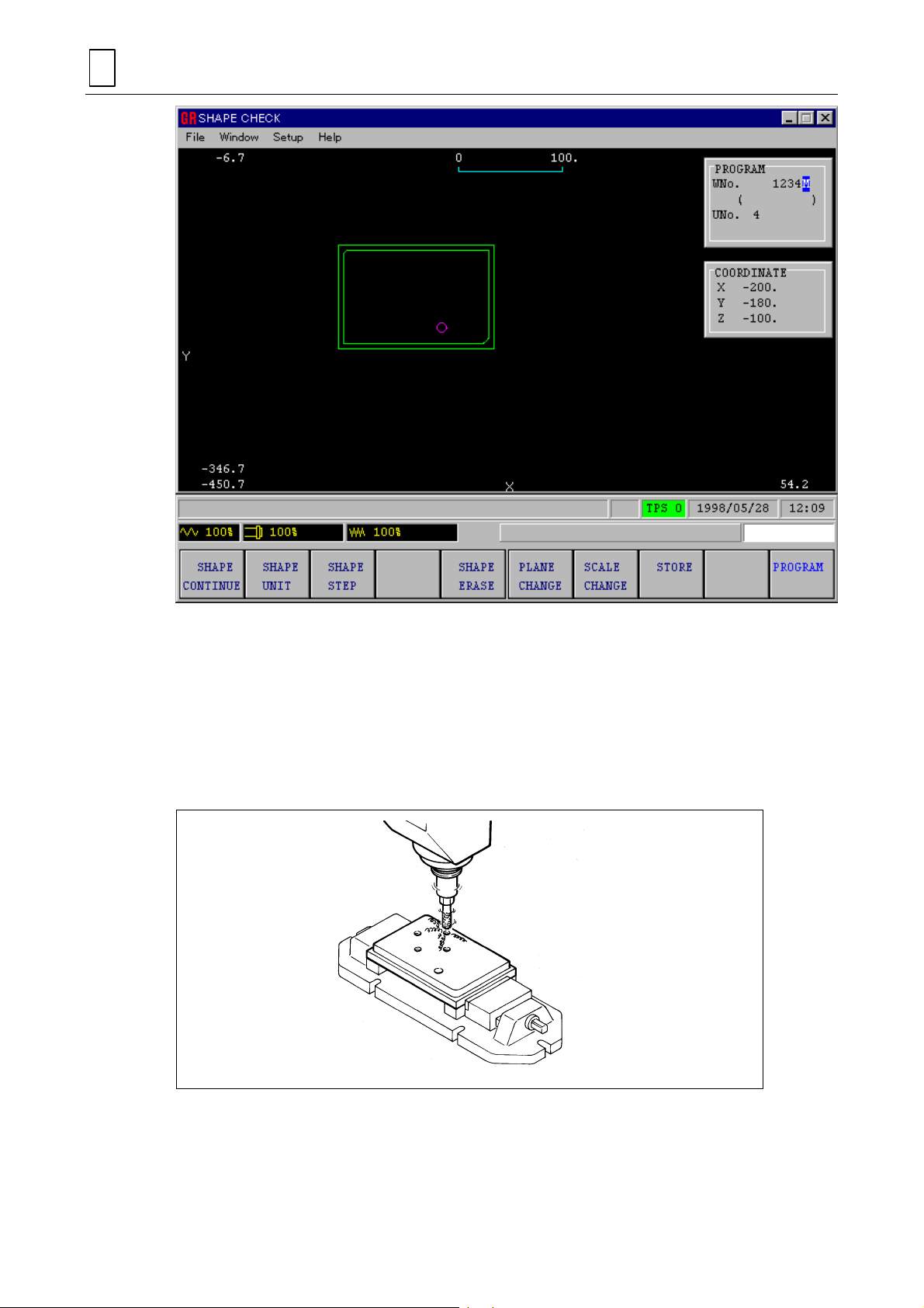
4
PROCEDURE BEFORE PERFORMING THE MACHINI NG
(10) Press the menu key
This completes the creation of a point machining unit.
4-4-10 Point machining unit (2)
Let us create a unit th at is used to dr ill four M8 tapped through-ho les. This m achining pro gram
unit is referred to as a tapping unit.
PROGRAM
to resume the
PROGRAM
D735P0039E
display.
1. Creation of point machining unit (2)
(1) While the message
MACH-ING
MACHINING UNIT <MENU>?
(2)
.
MACHINING UNIT <MENU>?
is displayed, press the m enu key
........................................................
4-46
NM210-00520
POINT
TAPPING
Page 77

PROCEDURE BEFORE PERFORMING THE MACHI NING
4
(3) Press the menu key
HELP
.
D735P0040E
Now, start creating the point m achining unit. The data for the ar ticle NOM-φ, TAP-DEP will be
specified here.
TYPE OF TAP?
(4)
ACTUAL DIAMETER OF TAP?
(5)
(Setting of the nom inal diameter causes autom atic setting of the outer diameter, the pitch
and the amount of chamfering.)
TAPPING DEPTH?
(6)
CHAMFER WIDTH?
(7)
CHIP VAC. CLEANER <Y:1, N:0>?
(8)
A point machining un it such as that shown belo w is now completed. This s hows that after the
data input for the point machining unit, a spot, a drill and a tap ha ve bee n automatically selec ted
for the tool sequence that is to be programmed.
.............................................................................
.....................................................
........................................................................
.......................................................................
..............................................
METRIC THRD (M)
8
2 0
4-47
Page 78

4
PROCEDURE BEFORE PERFORMING THE MACHINI NG
2. Creation of tool sequence
(1) Pr ess the cursor k ey
the article C-SP.
CUTTING SPEED, AUTO
(2)
FEEDRATE, AUTO
(3)
M CODE?
(4)
M CODE?
(5)
(6) Press the cursor key
the article C-SP.
CUTTING SPEED, AUTO
(7)
FEEDRATE, AUTO
(8)
M CODE?
(9)
M CODE?
(10)
(11) Press the cursor key
the article C-SP.
.......................................................................................
.......................................................................................
.......................................................................................
.......................................................................................
six times in succession to move the cursor to the position under
<MENU>?
→→→→
<MENU>?
→→→→
eight times in succession to move the cursor to the position under
<MENU>?
→→→→
<MENU>?
→→→→
eight times in succession to move the cursor to the position under
........................................
..................................................
........................................
..................................................
HSS AUTO
HSS AUTO
HSS AUTO
HSS AUTO
D735P0041E
CUTTING SPEED, AUTO
(12)
FEEDRATE, AUTO
(13)
M CODE?
(14)
.......................................................................................
→→→→
<MENU>?
→→→→
<MENU>?
........................................
..................................................
4-48
HSS AUTO
HSS AUTO
Page 79

PROCEDURE BEFORE PERFORMING THE MACHI NING
M CODE?
(15)
.......................................................................................
A tool sequence such as that shown below is now completed.
4
3. Creation of shape sequence
Next, create a shape sequence. For ta pping, four holes are to be drilled . These holes are to be
set as one shape, as shown below.
25 (Radius of circle - R)
(Y coordinate of
circle center)
60
(X coordinate of circle center)
(1) W hile the mes sage
CIRCLE
key
.
50
POINT CUTTING PATTERN <MENU>?
Start point
M3P057
is displayed, press the menu
D735P0042E
Z VALUE OF WORK SURFACE?
(2)
CIRCLE CENTER X?
(3)
.....................................................................
.................................................
4-49
0
5 0
Page 80

4
PROCEDURE BEFORE PERFORMING THE MACHINI NG
CIRCLE CENTER Y?
(4)
ANGLE OF START PT FROM X AXIS?
(5)
(
Input the angle of the line co nnect ing the center of the c ircle an d the f irst hol e to be drille d
.....................................................................
........................................
6 0
0
with respect to the X axis.)
Example 1: Example 2:
Start point
Center
45°
2 5
0°
M3P058
CIRCLE RADIUS R?
(6)
270°
Start point
Center
0°
–90°
.....................................................................
NUMBER OF HOLES?
(7)
RETURN POSITION <INIT:0, R:1>?
(8)
.................................................................
.............................................
(For Return position see Fig. 4-13.)
POINT CUTTING PATTERN <MENU>?
(9)
........................................
A shape sequence such as that shown below is now completed.
4
1
SHAPE END
4-50
Page 81
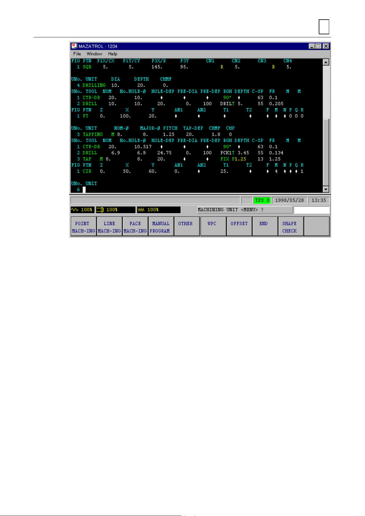
PROCEDURE BEFORE PERFORMING THE MACHI NING
4
4. Shape check
Let us call shapes on the
(1) Press the menu key
(2) Press the menu key
SHAPE CHECK
SHAPE CHECK.
SHAPE CONTINUE.
display.
D735P0043E
4-51
Page 82

4
PROCEDURE BEFORE PERFORMING THE MACHINI NG
(3) Press the menu key
(4) Press the menu key
The reverse-display status of
displayed.
The following display shows the unit number 4 shape of point machining unit (1).
SHAPE ERASE
SHAPE UNIT
several times to display shapes on a unit basis.
SHAPE UNIT
to erase the shape.
is cleared when the final shape has been
D735P0044E
4-52
Page 83

PROCEDURE BEFORE PERFORMING THE MACHI NING
4
(5) Press the menu key
This completes the creation of a point machining (tapping) unit.
4-4-11 End unit
Let us create an end unit that indicates the end of the program.
(1) While the message
CONTINUE <Y:1, N:0>?
(2)
(Specify whether or not the m achining program is to be repeated. If 0, the pr ogram ends
with the particular step. If 1, the program returns to its beginning and returns to machine the
next workpiece.)
PARTS COUNTER <Y:1, N:0>?
(3)
(Specify whether or not the number of times that the machining operation has been
repeated is to be counted. If 0, counting does not occur. If 1, counting occurs and the results
are displayed on the
An end unit such as that shown below is now completed, which m eans that the creation of the
program is to be ended.
PROGRAM
MACHINING UNIT <MENU>?
POSITION
to resume the
...............................................................
...................................................
display of the screen.)
PROGRAM
is displayed, press the menu key
display.
D735P0045E
END
.
0
0
4-53
Page 84

4
PROCEDURE BEFORE PERFORMING THE MACHINI NG
4-4-12 End of the program
(1) Press the menu selector key.
(2) Press the menu key
Display of the created program
Let us trace the create d program back to its beginning. R epeated depress ion of the cursor k ey
causes the screen to scr oll up c ont inu ous ly to display the part of the program that precedes
the existing part. Depressing of the cursor key
In addition, the program can also be checked using the page keys
however, the cursor moves on a unit basis.
The following shows the entire program (actuate the cursor keys to check the program):
PROGRAM COMPLETE
.
causes the program to advance.
D735P0046E
. In this case,
4-54
Page 85

PROCEDURE BEFORE PERFORMING THE MACHI NING
UNo. MAT INITIAL-Z ATC MODE MULTI MODE MULTI FLAG PITCH-X PITCH-Y
0 S45C 20. 1 OFF
UNo. UNIT ADD. WPC X Y th Z 4
1 WPC-1 -300. -200. 0. -100. 0.
UNo. UNIT DEPTH SRV-Z BTM WAL FIN-Z FIN-R
2 FACE MIL 0. 3. 2
SNo. TOOL NOM-φ No. APRCH-X APRCH-Y TYPE ZFD DEP-Z WID-R C-SP FR M M
R1 F-MILL 80.A ? ? XBI
FIG PTN P1X/CX P1Y/CY P3X/R P3Y CN1 CN2 CN3 CN4
1 SQR 0. 0. 150. 100.
UNo. UNIT DEPTH SRV-Z SRV-R RGH CHMF FIN-Z FIN-R
3 LINE OUT 10. 10. 5. 3
SNo. TOOL NOM-φ No. APRCH-X APRCH-Y TYPE ZFD DEP-Z WID-R C-SP FR M M
R1 E-MILL 10.A ? ? CW G01 10.
FIG PTN P1X/CX P1Y/CY P3X/R P3Y CN1 CN2 CN3 CN4
1 SQR 5. 5. 145. 95. R5. R5.
UNo. UNIT DIA DEPTH CHMF
4 DRILLING 10. 20. 0.
SNo. TOOL NOM-φ No. HOLE-φ HOLE-DEP PRE-DIA PRE-DEP RGH DEPTH C-SP FR M M
12CTR-DR
DRILL
FIGPTN ZXYAN1AN2T1T2FMNPQR
1 PT 0. 100. 20.
UNo. UNIT NOM-φ MAJOR-φ PITCH TAP-DEP CHMF CHP
5 TAPPING M8. 8. 1.25 20. 1.8 0
SNo. TOOL NOM-φ No. HOLE-φ HOLE-DEP PRE-DIA PRE-DEP RGH DEPTH C-SP FR M M
1
CTR-DR
2
DRILL
3
TAP
FIGPTN ZXYAN1AN2T1T2FMNPQR
1 CIR 0. 50. 60. 0.
UNo. UNIT CONTI. NUMBER ATC XYZ4ANGLE
6 END 0 0
20.
10.
20.
6.9
M8.
10.
10.
"""""""
10.517
6.9
8.
"
20.
"
24.75
20.
"
25.
"
"
"
0.
"
0.
"
""
100.
0.
0. 0.
"
100
"
"
"
"""
"
"
3. 56. 121 1.079
"
54 0.027
90°
DRIL"T5.6355
90°
PCK1
FIX
"""
4
CW
000
"
T3.45
P1.25
63
55
13
0.1
0.205
0.1
0.134
1.25
1
4
Fig. 4-14 Sample program
4-55
Page 86

4
PROCEDURE BEFORE PERFORMING THE MACHINI NG
4-5
Registration of Tools in a Tool Data File
During creation of a program, the names and nominal diameters of the tools required for
machining should have already been input. To m achine a workpiece by automatic run, those
tools must be mounted in a tool maga zine in adva nce. In addit ion, the tools t o be m ounted in a
tool magazine must be registered in a tool data file. Reg istration of tools in a tool data file is
referred to as assignment of pocket numbers to the tools.
4-5-1 Pocket numbers and tool numbers
The pocket number refers to the number inscribed on the side face of the pocket of a tool
magazine. The tool that h as been mounted in the pock et is s pec if ied by the pocket number . T he
identification number of the pocket which accommodates a tool is called tool number.
Tool magazine model V
Tool magazine model H
This tool is referred
to as the tool having
tool No. 4.
These numbers are
referred to as pocket
numbers.
Note:
NM210-00529
The design of the tool m agazine slightl y differs according to the t ype of m achine to be
used.
4-56
Page 87

4-5-2 TOOL DATA display
PROCEDURE BEFORE PERFORMING THE MACHI NING
4
Carry out the following key operations to call the
(1) Press the display selelctor key.
(2) Press the menu key
!
The
Function of
TOOL DATA
The
tools are displa yed in order of pocket num ber; the pocket numbers being displayed on the left
end of the screen.
If no tool types are being displayed on the s c reen, this ind ic ates that no tools are mounted in the
tool magazine. The pocket numbers on the
numbers of the tool magazine. The relationship between these two types of pocket numbers can
be represented as shown below.
TOOL DATA
TOOL DATA
display shows the t ypes of tools mounted in the tool magazine. T he types of
TOOL DATA
display will then be presented as shown below.
display
.
TOOL DATA
TOOL DATA
display:
display correspond to the pocket
Fig. 4-15 Correspondence to the pocket numbers
4-57
D735P0047ED735P0047ENM210-00530
Page 88

4
PROCEDURE BEFORE PERFORMING THE MACHINI NG
- NOTE -
4-58
Page 89

4-5-3 TOOL LAYOUT display
PROCEDURE BEFORE PERFORMING THE MACHI NING
4
Carry out the following key operation to call the
(1) Press the display selector key.
(2) Press the menu key
!
The following
TOOL LAYOUT
TOOL LAYOUT
.
display will be presented.
TOOL LAYOUT
display:
D735P0048E
Function of
TOOL LAYOUT
The
are to be registered in a tool data file. This display consists of two sections:
NEXT display on the right side, and CURRENT display on the left side. On the CURRENT
display, tool nam es and pocket numbers ar e indicated in the sam e state as that of the
DATA
tools that have been set o n the program and ass ignment of pocket num bers to them . W hen the
setup operations are completed, the tools on the NEXT display will be registered on the
CURRENT display (tool data).
The following figure shows the relationship between the
display and
TOOL LAYOUT
display is the display on which the tools that have been set on the program
display. The NEXT display is used to carry out set up operations such as displa y of the
TOOL LAYOUT
display
display:
PROGRAM
display,
TOOL
TOOL DATA
4-59
Page 90

4
PROCEDURE BEFORE PERFORMING THE MACHINI NG
The CURRENT display and the
display always possess the same contents .
Thus, the tool data als o changes when new tools
have been registered on the CURRENT display.
TOOL DATA
3
D735P0049E
3
D735P0050LE
4-60
Page 91

PROCEDURE BEFORE PERFORMING THE MACHI NING
4
Registration of new tools
2
The tools that have been
set on the program are displayed.
1
D735P0051E
4-61
D835P0050RE
Page 92
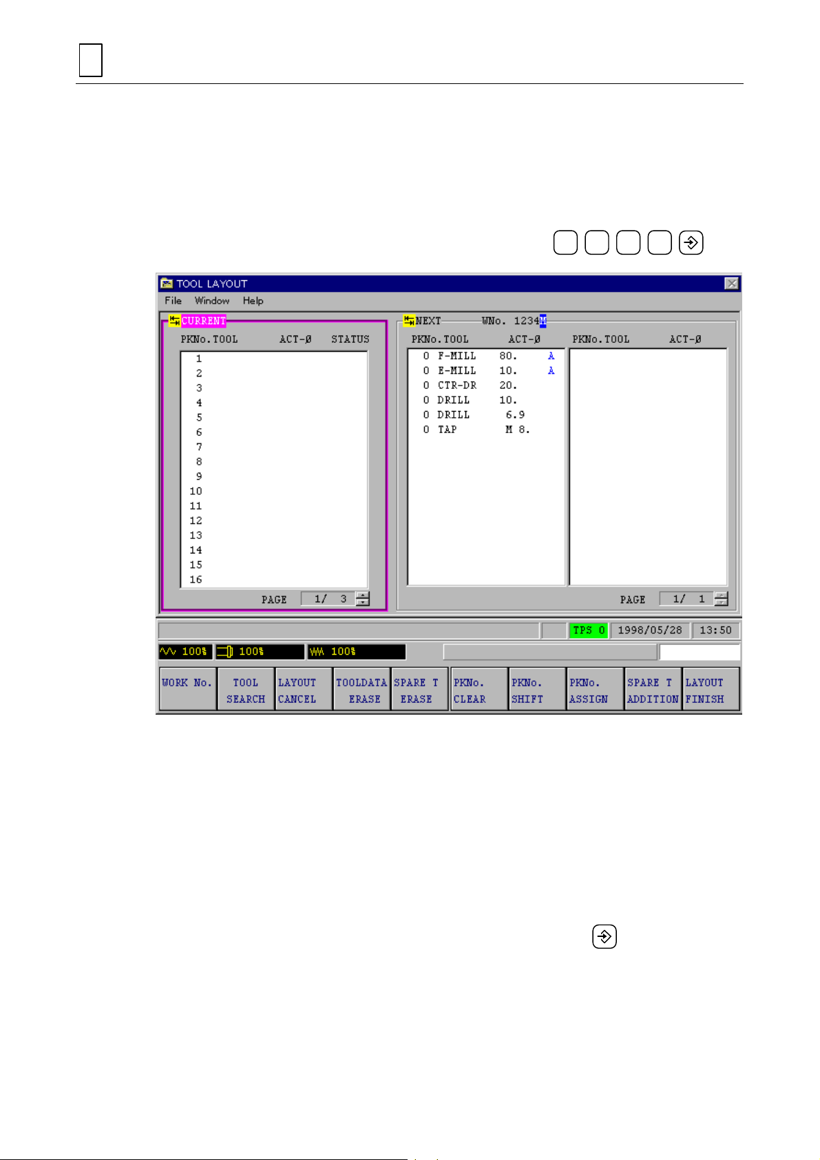
4
PROCEDURE BEFORE PERFORMING THE MACHINI NG
4-5-4 Registration of tools
The display of m enu data
NUMBER?
which has been previously created in Section 4-4.
See Section 5-1, “ TOO L LAYOUT Dis play” of the Oper ating Manual f or detai ls of registrat ion of
tools.
(1)
is displayed on the
WORKPIECE PROGRAM NUMBER?
WORK No.
TOOL LAYOUT
is reversed, and the m essage
display. Input the work number of the program
.................................
WORKPIECE PROGRAM
1 2 3 4
D735P0052E
The tools that have been set on the program having work No. 1234 will t hen be displayed as
shown on the NEXT display. Let us assign pocket numbers to the displayed tools.
Three modes are available for assigning pocket numbers: automatic, manual, and shift.
Automatic assignment, the simplest of these three modes, is described below.
Note:
(2)
(3)
If automatic assignment is performed, data of the registered tools will be erased
entirely. To prevent this data erasure, eit her the m anual assignment m ode or the s hift
mode must be used.
PKNo. SHIFT OR ASSIGN <MENU>?
POCKET NUMBER ASSIGN <INPUT>?
!
Pocket numbers will then be assigned to the tools as shown below.
..........................................
.......................................
4-62
PKNo. ASSIGN
Page 93

PROCEDURE BEFORE PERFORMING THE MACHI NING
4
D735P0053E
Next, carry out the fol lowing key operations to r egister the tools on t he NEXT display onto the
CURRENT display.
LAYOUT FINISH <MENU>?
(4)
LAYOUT FINISH <INPUT>?
(5)
LAYOUT FINISH
(6)
!
The tools will be registered on the CURRENT display as shown below.
..........................................................
..........................................................
LAYOUT FINISH
4-63
Page 94

4
PROCEDURE BEFORE PERFORMING THE MACHINI NG
Let us recall the
(7) Press the display selector key.
(8) Press the menu key
!
The tools th at h av e b een registered in the
the
TOOL DATA
TOOL DATA
display on the screen.
TOOL DATA
display, as shown below.
D735P0054E
.
TOOL LAYOUT
display will be pres e nted in
4-64
Page 95

PROCEDURE BEFORE PERFORMING THE MACHI NING
4
4-6 Check of the Machining Path
Let us return the
(1) Press the display selector key.
(2) Press the menu key
!
The program with work No. 1234 will be displayed as shown below.
Next, let us call the
display. See Section 6-2, “TOOL PATH CHECK Display” of the Operating Manual for details.
PROGRAM
PROGRAM
TOOL PATH
display.
D735P0055E
.
display on the screen and check the machining path on that
4-65
Page 96

4
PROCEDURE BEFORE PERFORMING THE MACHINI NG
(3) Press the menu key
!
The following
TOOL PATH
TOOL PATH
D735P0051E
.
display will be presented.
4-66
D7350056E
Page 97

PROCEDURE BEFORE PERFORMING THE MACHI NING
4
(4) Press the menu key
(5) Next, press the menu key
through to the end.
PART SHAPE
to display shapes continuously.
PATH CONTINUE
to display the machining path of the tool
(6) Press the menu key
(7) Pr es s the menu key
reverse-display state of the menu continues until the entire machining path appeared.
PATH ERASE
PATH STEP
to erase the machining path of the tool.
several times to displa y the mac hining pat h in steps . The
D735P0057E
4-67
Page 98

4
PROCEDURE BEFORE PERFORMING THE MACHINI NG
D735P0058E
(8) To check the machining path in further details, use the PLANE CHANGE function (see
Subsection 4-4-8) or the SCALE CHANGE function (see Subsection 4-4-9).
(9) W hen the all operatio n has been com pleted, press th e display selector key and the m enu
POSITION
key
to resume the
POSITION
display.
4-68
E
Page 99

PART 2
MAZATROL PROGRAM FUNCTIONS
Part 2 describes all the functions of the MAZATROL program.
H735P20019E
Page 100

 Loading...