

Page 1
1_
F>
.A,
V~
C
LJ
m
—
nAXNTENANCE
MNT
D
S
P
I
address
display
display
CM
mi
OFF.
PLC
al
screen
below.
tf
NT)
ssi
so
en
Wh
can
is
that
display
is
ng
The
be
will
y
used
mernor
The
...
).
).
"Y":
)ÿ
"M"
.1,
)ÿ
"D":
)ÿ
"F":
)ÿ
"R":
)ÿ
"L":
).
"P":
t
h
be
similar
the
PLC
add
be
PLC
11
s
X11
;
;
T”
ma
i
e
is
you
esses
r
to
explained
n
monitored
found
will
"Q"
I/F
screen
force
memory
INPUTS
).
).
)
).
.
XO
XI
X
XI
1
00
70
SO
THRU
OUTPUTS
>.
)
.
>.
PLC
The
durinq
PLC
>.
).
).
).
DATA
The
storing
change,
registers
FAULT;
Machine
THRU
Y0
00
Y
1
Y
1
SO
TEMPORARY
status
TIMERS
TO
THRU
T
000
1
T2000
T3000
REGISTERS
machine
detected
generated
alarms
and
PLC
These
listed
that
to
part,
data
32S
that
REGISTERS
addresses
above.
the
up-dated
be
the
that
LATCHING
These
power
PLC
addresses
is
"C"
or
t
enanc
e
on
but
to,
on
earlier
not
function
is
that
the
in
are
this
addresses
TO
THE
XFF
THRU
THRU
THRU
FROM
X
X17F:
X24F
THE
YFF
THRU
THRU
the
Y17F:
Y20F
of
power
(Decimal).
27
T
1
THRU
THRU
THRU
and
the
vital
so
do
are
ALARMS
side
by
&
malfunctions
the
by
PLC
thru
will
(Decimal).
The
"D"
registers
"R"
addresses
will
ADDRESSES
turned
LANGUAGE
PLC
MNT)
C
i
sp
d
1
ay
the
radically
MAZATRQL
find
memory
PLC
:
6F
1
:
reference
that
primarily
was
used
addresses
section
and
CHexi
INPUTS
:
INPUTS
MMS
:
INPUTS
(Hexi
PLC
OUTPUTS
in
their
-dec
FROM
INPUTS.
TO
OUTPUTS
:
OUTPUTS
MEMORY
these
:
Til
27
T2127:
T3127:
(Decimal).
control
the
of
the
(Decimal).
addresses
up
sequence.
TIMER
:
INPUTS
TIMER
SET
ACCUMULATED
data
data
at
register
IS
status
bit
MIS-OPERATIDNS
PLC.
Alarms
addresses
399
be
are
covered
main
alternate
an
in
used
much
difference
store
as
the
status
store
only
change
(Decimal
will
OFF/ON.
not
SUB-PROGRAMS
change
is
I/F
screen.
different
CNC's.
to
the
to
to
PLC
this
used
used
of
purpose
)
mal
i
MACHINE.
FROM
FROM
-deci
OPERATING
(Direct
THE
mal
MACHINE.
OPERATING
TO
NC.
TO
is
Cl
OUTPUTS
TIME
these
CIS
are
type.
(Decimal.
mis-operati
and
200
thru
FO
the
like
current
changes.
permanent
when
)ÿ
you
status
selected,
This
than,
On
the
8
an
bit
force
check
ladder
or
OFF.
ON
book.
in
.
inputs
NC.
)
.
established
Bit).
Bit).
Cl
Bit).
TIME
addresses.
values.
thru
CIS
kept
327
F127.
method
is
section
the
"D"
between
status
For
sequence
change
when
(Decimal).
any
screen
the
M-32
"H"
address.
address
the
status
sequence.
How
life
PANEL.
PANEL.
Bit).
current
As
All
data
FO
ons
are
FI
are
For
used
for
ALARMS.
addresses
the
two
that
the
most-
it.
the
PLC
memory
f
o
diagnostic
maintenance-:
Alsc
fail's
to
are
to
NO
by
things
27)
is
of
It
use
listed
.
ON
the
can
this
has
NC
t
h
e
'
&
I
j
n
i
j
L,
PAGE
1
!
Page 2
MAINTENANCE
DISPLAYS
PLC
I/F
memor
or
DISPLAY
the
add
r
esses
d
a
d
r
e
buttons
DISP
DISPLAY
Under
CLEAR
et
t
1
er
n
1
PLC
ladder.
ways.
t
h
appear
the
expected
PLC
two
i
wi'$
ADDRESS
While
y
addresses
SELECT
addresses
backwards.
.
s
ses
to
MND1
SELECT
SHIFT
The
normal
(SHIFT)
char
The
NORMAL
CURSOR
CURSOR
CURSOR
MINUS
7
3
—
9
DECIMAL
4
5
S
o
3
FORCING
Any
).
).
>.
.
.
.
After
e
c
o
T
go
MND2
cursor
ac
relationships
PLC
I/F
depends
The
ENTER
MOVE
ENTER
MOVE
ENTER
PRESS
thf'
First,
1
umn
in
FORWARD
the
h
FUNCTION
conditions
t
er
LEFT
RIGHT
DOWN
SIGN
display.
THE
the
PLC
can
forward
e
re
is
from
key
POINT
PLC
THE
0
o
one
liNDS
<->
control
.
s
<-)
ADDRESSES
memory
entirely
procedure.
ADDRESS
THE
CURSOR
"1"
FOR
CURSOR
TO
INPUT
THE
"force"
the
i
b
f
upper
/REVERSE
I/F
be
push-buttons.
o
is
pressed
)
C.
address
Whether
"ON"
ERASE
address
y
ar
n
screen
advanced
while
These
e
n
address
MND4
are
right
the
limitati
MNDS
and
they
as
ON
upon
..
.
AT
"DEVICE".
RIGHT
or
RIGHT
DATA,
PUSH-BUTTON.
has
been
will
bits.
corner
the
is
being
or
reversed
The
DISPLAY
push-buttons
y
n
,
o
group
number
are
first,
follows....
-----
-----
-----
-----
-----
------
------
-------
------
----
-----
AND/OR
------
can
or
the
TO
"0"
TO
1
Second,
to
MNDS
keys
what
they
AFTER
LETTER
SYMBOL
—
SYMBOL
—
------
LETTER
LETTER
LETTER
LETTER
LETTER
LETTER
LETTER
LETTER
LETTER
LETTER
LETTER
LETTER
OFF
be
forced
not
this
way
"DATA".
FOR
"OFF".
"MODE".
TO
PULSE
executed,
now
reflect
of
displayed,
MENU
the
the
SELECT
SELECT
a
u
c
o
another.
NNP7
serve
they
will
SHIFT
"P"
"+"
"/"
"A"
"B"
"C"
"D"
"E"
"F"
"L"
"R"
"X"
"Y"
"M"
"T"
will
the
ADDRESS,
address
display.
by
pressing
push-button
affect
n n
to
the
t
o
MND8
a
appear
yield
a
result
address
display
forced
the
push-button
u
s
MENU
dual
to
"1"
or
and
See?
two
the
both
e
these
..
MNDS
SELECT
purpose
be
either
or
a
the
in
is
used
TO
2
will
status,
the
next
columns
MENU
will
columns
two
MENU
(
but
symbols
"0"
on
result
within
LATCH.
change
forced
page
SELECT
will
\
/e.'&'the
no
i
push
-(-
)
life.
in
when
this,
in
0
or
state
.
.
.
.
of
move
of
the
or
you
the
1
,
—
I
i
I
(
i
(
(
{
(
(
(
PAGE
2
Page 3
<NC
ALARM
>
CPLC
I
/FI
SET
<
DATA>
DIAGN
5
X
0002=1
XOOOC=
1
X001F=0
Y002D=1
<STOF
ALARM
<
OPERATOR
<
VERSION
CODE
MESSAGE
!
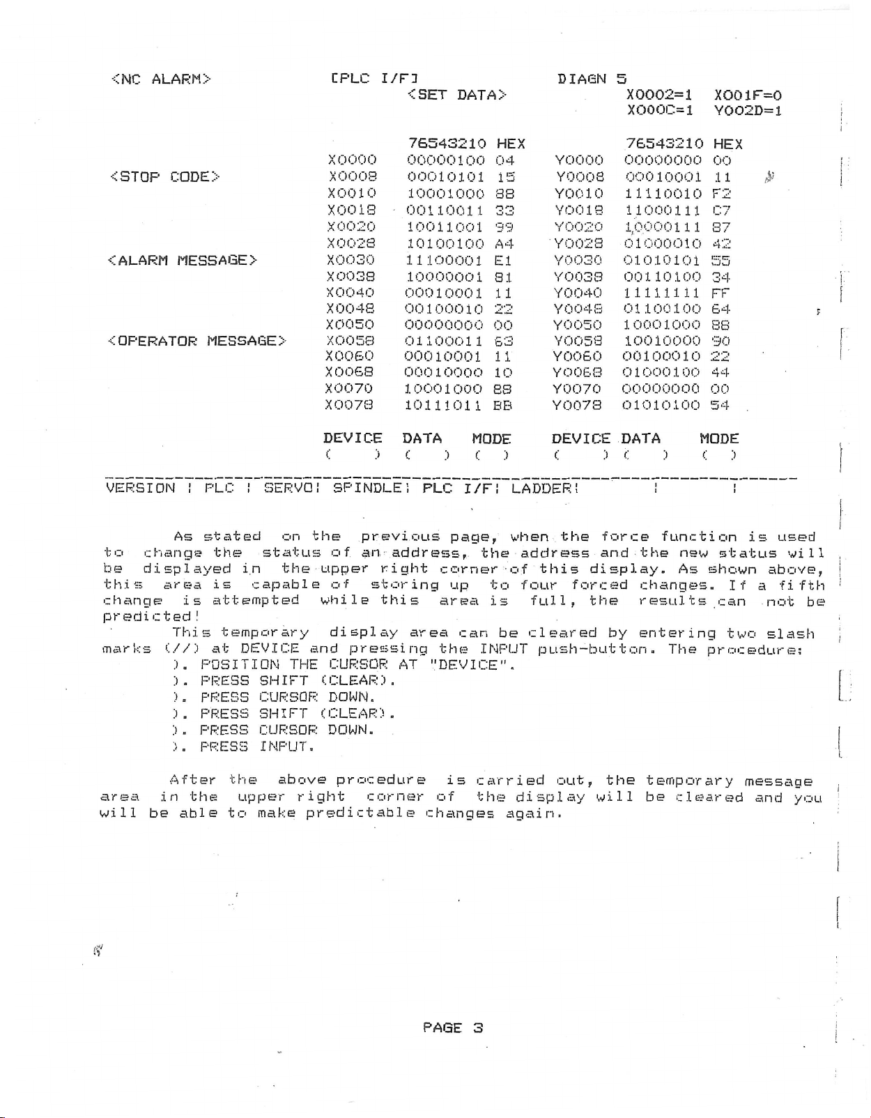
As
to
change
be
displayed
this
change
predicted!
marks
area
is
This
(//)
).
).
).
).
).
).
>
>
MESSAGE
SERVO!
!
PLC
stated
the
is
attempted
at
POSITION
PRESS
PRESS
PRESS
PRESS
PRESS
status
i.n
capable
temporary
DEVICE
SHIFT
CURSOR
SHIFT
CURSOR
INPUT.
>
on
the
THE
X0000
X0008
X0010
X001S
0020
X
X0023
X0030
X003S
X0040
X004S
X0050
X0053
X0060
X0068
X0070
X0073
DEVICE
c
SFTNDLE
the
of
upper
of
while
display
and
pressing
CURSOR
(CLEAR).
DOWN.
(CLEAR).
DOWN.
76543210
00000100
00010101
10001000
00110011
10011001
10100100
11100001
10000001
00010001
00100010
00000000
01100011
00010001
00010000
10001000
10111011
DATA
)
c
!
previous
an
address,
right
storing
this
area
AT
'"DEVICE".
:>
PLC
page,
corner
up
area
the
MODE
<:
I/F!
can
HEX
04
15
33
33
39
A
4
El
31
11
22
00
£3
11
10
83
BB
:>
LADDER!
when
the
of
to
is
be
INPUT
0000
Y
Y0003
Y0010
3
YOO
1
Y0020
Y002S
Y
0030
Y0033
Y0040
Y004S
Y0050
YOO
3
5
Y0060
Y006S
Y0070
Y0073
DEVICE
c
the
address
this
four
full,
:>
force
and
display.
forced
the
cleared
push-button.
76543210
00000000
00010001
11110010
11000111
1,0000111
01000010
01010101
00110100
11111111
01100100
10001000
10010000
00100010
01000100
00000000
01010100
DATA
:>
<
function
the
changes.
results
by
entering
The
HEX
00
11
F2
C7
37
42
55
34
FF
64
SB
90
22
44
00
54
MODE
c
new
status
As
shown
can
two
procedure:
:>
!
If
is
above,
a
not
slash
used
will
fifth
be
:
?
F
i-
!
1
!
i
area
will
(f
in
be
After
the
able
the
upper
to
above
make
procedure
right
predictable
corner
is
of
changes
PAGE
3
carried
the
display
again.
out,
the
will
temporary
be
cleared
message
and
you
!
i
Page 4
MAINTENANCE
DISPLAY:
PLC
I/F
NC
<
ALARM
<STOP
ALARM
<
<
OPERATOR
VERSION!
CDDE>
>
MESSAGE
MESS
PLC
>
AGE
SERVO!
i
CPLC
xoooo
X0008
X0010
X0018
X0020
X0028
X0030
X0038
X0040
X0048
X0050
>
X0058
X0060
X0068
X0070
X007S
DEVICE
c
SPINDLE
I/F:
<SET
76543210
00000000
00000101
1000.1000
00110011
10011001
10100100
11100001
10000001
00010001
00100010
00000000
01100011
00010001
00010000
10001000
10111011
DATA
c
:>
PLC
!
DAT
:>
I/F!,
A
>
HEX
00
05
3S
33
99
4
A
El
81
11
22
00
S3
11
10
88
BB
MODE
c
:>
LADDER!
DIAGN
YOOOO
Y0008
YOO
YOGI
YOO
Y002S
Y0030
YOO
Y0040
YOO
Y0050
YOO
Y0060
YOO
Y0070
YOO
DEVICE
c
1
20
3
4
58
68
7
0
8
8
8
8
:>
5
76543210
00000000
00010001
10010
i’ll
11000111
100Q01U
01000010
01010101
00110100
111 1
1
1
01100100
10001000
10010000
00100010
01000100
00000000
0
1
0
101
00
DATA
)
<:
!
1
1
HEX
00
11
F2
07
87
42
55
34
FF
64
88
90
22
44
00
54
MODE
>
!
&
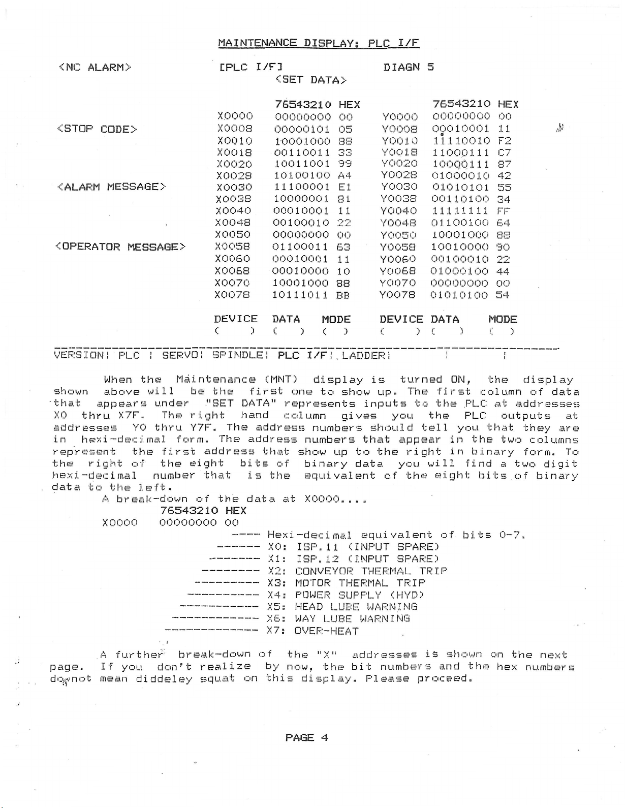
shown
thru
hexi—
right
-dec
i
to
appears
'that
XO
addresses
in
represent
the
hex
data
page.
dcÿnot
When
above
.i
the
A
the
X7F.
YO
decimal
the
of
mal
left.
break-down
xoooo
A
further
If
you
mean
diddeley
Maintenance
will
under
The
thru
form.
first
the
number
76543210
00000000
break—
don't
be
the
."SET
right
Y7F.
The
address
eight
that
of
the
realize
squat
(MNT)
first
DATA"
hand
The
address
address
that
bits
.is
data
HEX
00
----
---
----
---
-----
----
----
----
down
----
on
the
Hexi
XO:
XI:
X2:
X3s
X
X5
XS
X7
of
by
this
4
of
at
:
:
:
:
display
one
to
show
represents
column
numbers
show
binary
equivalent
XOOOO....
-dec
ISP.
ISP.
CONVEYOR
MOTOR
POWER
HEAD
WAY
OVER-HEAT
the
now,
display.
gives
numbers
up
i
mal
11
12
THERMAL
SUPPLY
LUBE
LUBE
"X"
the
inputs
that
to
data
equivalent
(INPUT
(INPUT
THERMAL
WARNING
WARNING
addresses
bit
Please
turned
is
up.
you
should
appear
the
you
of
SPARE)
SPARE)
TRIP
(HYD)
numbers
first
The
to
the
the
tell
right
will
the
eight
TRIP
is
and
proceed.
ON,
PLC
you
in
in
of
bits
shown
the
column
PLC
that
the
binary
find
bits
on
the
display
at
addresses
outputs
they
two
form.
a
two
of
0-7.
the
hex
numbers
data
of
at
are
columns
To
digit
binary
next
PAGE
4
Page 5
MAINTENANCE
DISPLAY
PLC
I/F
;
addresse
what
address
and/or
the
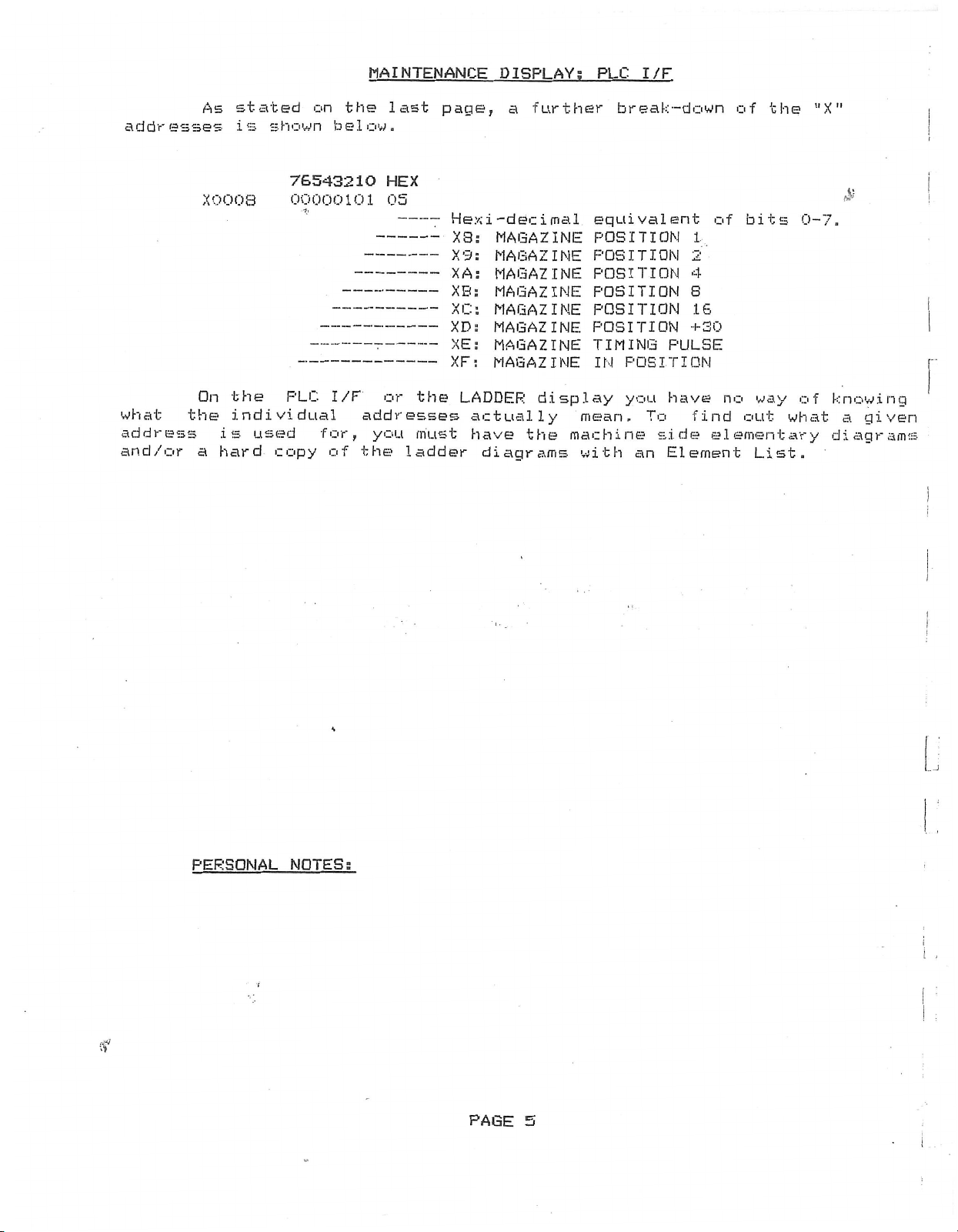
stated
As
s
s
i
X0003
On
the
individual
used
is
a
hard
on
n
s
o
h
w
76543210
00000101
PLC
for
copy
the
b
w
e1o
I/F
addresses
y
!
the
of
last
.
HEX
05
or
u
o
page
Hexi-decimal
X3:
-
—
X9:
-----
XA:
XB:
---
XC:
-----
XD;
---
XE:
---
XF:
---
----
the
---
ladder
LADDER
must
a
further
f
MAGAZINE
MAGAZINE
MAGAZINE
MAGAZINE
MAGAZINE
MAGAZINE
MAGAZINE
MAGAZINE
display
actually
have
the
diagrams
machin
break-down
equivalent
POSITION
POSITION
POSITION
POSITION
POSITION
POSITION
TIMING
POSITION
IN
you
e
an
To
s
mean.
with
of
1
2
4
S
16
+30
PULSE
have
i
Element
find
d
e
no
e
lement
of
bits
u
o
List.
the
way
t
0-7.
of
w
h
r
a
"X"
Jt
knowing
t
a
a
d
y
i
g
a
gram
e
i
n
v
s
PERSONAL
'
NOTES;
PAGE
5
Page 6
<NC
ALARM
>
MAINTENANCE
L
1
I/F
PLC
<SET
DISPLAY:
DATA>
FLC
DIAGN
I/F
5
<STOP
ALARM
<
OPERATOR
<
CODE
MESSAGE
VERSION!
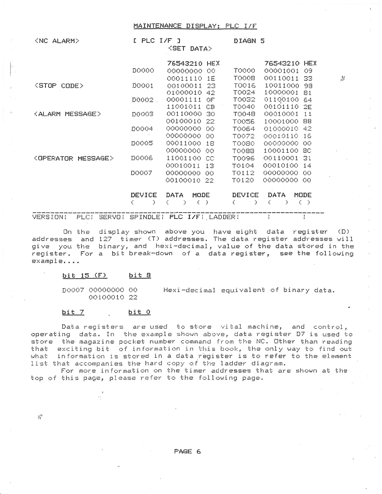
On
addresses
give
register.
exampl
you
e.
>
MESSAGE
PLC!
the
and
the
For
.
.
.
>
>
SERVO!
display
127
binary,
a
bit
DO
000
DO
00
D0002
DO
003
004
DO
D0005
DO
006
00
7
DO
DEVICE
c
SPINDLE!
shown
timer
break-down
CT>
and
76543210
00000000
00011110
1
00100011
01000010
00001111
11001011
00110000
00100010
00000000
00000000
00011000
00000000
11001100
00010011
00000000
00100010
DATA
:>
C
PLC
above
addresses.
hex
i
-dec
42
CB
30
22
00
00
18
00
cc
13
00
22
MODE
:>
of
)
<
I/F!
you
i
mal,value
a
HEX
00
IE
23
OF
LADDER!
have
The
data
TO
000
TOOOS
6
1
TOO
024
TO
342
TOO
40
TOO
48
TOO
56
TOO
6
4
TOO
T0072
TO
080
TOO
S3
TOO
9
6
04
1
TO
.1
12
0
T
TO
1
20
00000000
DEVICE
eight
of
}
register
the
c
data
register,
76543210
00001001
00110011
10011000
10000001
0.1
001
00010001
10001000
01000010
00010110
100
100
Ol'l
10
00000000
10001100
00110001
00010100
00000000
DATA
c
:>
!
data
register
data
see
HEX
09
33
93
81
64
2E
11
SB
42
IS
00
sc
31
14
00
00
MODE
c
>
!
addresses
stored
the
following
in
$
CD)
will
the
era
p
o
store
that
what
t t
s
i
1
top
of
bit
15
D0007
7
bit
D
atare
t
i
e
information
h
g
n
the
x
c
i
ata
For
this
d
a
magazine
t
i
n
o
c
c
more
page,
CF)
00000000
00100010
gisters
.
a
In
t
bit
g
is
m
p
a
i
n
e
information
please
bit
00
22
bit
a
r
t
e
h
pocket
.i
n
f
o
stored
e
t
s
h
3
0
u.se
e
exa
m
number
m
r
f
o
in
a
r
h
on
refer
p
a
d
Hex
d
e
.1
t
i
a
c
o
the
to
i
-dec
to
s
h
o
command
n
o
in
data
p
y
timer
the
PAGE
mal
i
sto
e
r
n
w
a
b
is
1-
1
>
register
t
o
e
f
h
addresses
following
6
equivalent
t
a
i
1
v
d
bo
1
a
,
the
,
o
k
is
e
d
a
d
ove
from
achine,
m
r
t
a
NC.
the
to
i
d
r
that
page.
of
gist
e
only
refer
a
g
r
binary
r
e
Other
w
.
a
m
are
a
d
n
D
7
than
a
y
to
shown
data.
control
s
i
t
o
find
the
,
u
s
t
e
d
reading
ou
element
at
the
o
t
Page 7
MAINTENANCE
DISPLAY:
PLC
I/F
<NC
ALARM
<STOP
ALARM
<
OPERATOR
<
VERSION!
>
CODE
>
MESSAGE
MESSAGE
PLC!
>
>
SERVO!
[
PLC
TO
000
TOO
OS
TOO
16
TOO
24
T0032
TOO
40
TOO
43
T005S
TO
064
TO
072
TO
080
TO
088
TOO
96
TO
104
TO
1
1
2
TO
1
20
DEVICE
c
SPINDLE!
>
I/F
1
<SET
76543210
00100011
00000000
10011000
00111100
00000001
00000000
00000000
10101010
00010011
10001000
00000000
10011001
01000100
00100011
01100000
00000000
DATA
c
:>
PLC
DAT
I/F!
A
>
HEX
23
00
98
3C
01
00
00
A
13
38
00
99
44
23
60
00
MODE
<:
:>
DIAGN
T
T
T101S
T
T
T
T
A
T
T
T
T
T
T
T1
T
Ti
DEVICE
<:
LADDER!
1
000
1
008
024
1
032
1
040
1
040
1
056
1
1064
1
072
080
1
1
088
1
096
104
.1
1
1
120
5
76543210
00100011
00000000
10011000
00111100
00000001
00000000
00000000
10101010
00010011
10001000
00000000
10011001
01000100
00100011
01100000
2
00000000
DATA
c
:>
:>
HEX
23
00
98
3C
01
00
00
A
A
13
38
00
99
44
23
SO
00
MODE
c
:>
j
f
&
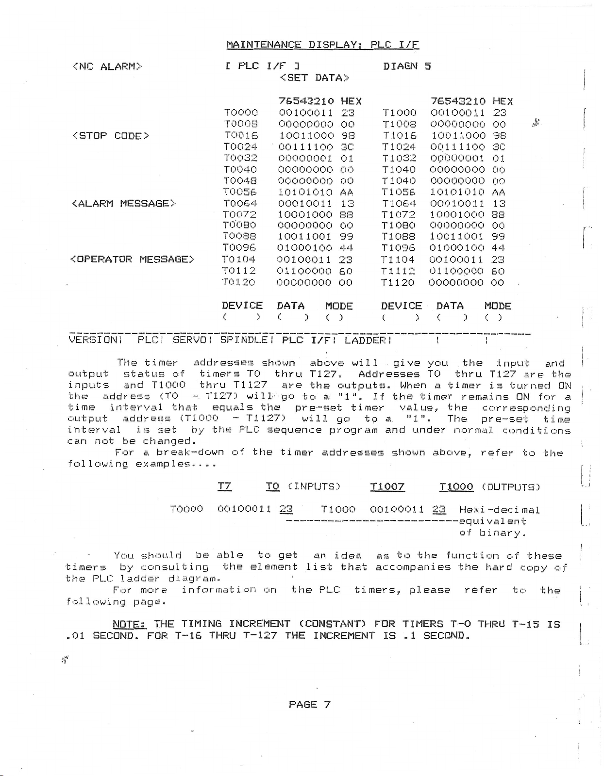
output
inputs
the
time
output
interval
can
foil
address
interval
not
For
o
.i
w
n
You
timers
PLC
the
For
following
NOTE:
SECOND.FOR
.01
The
timer
status
and
T1000
address
is
changed.
be
a
e
a
g
x
should
consulting
by
ladder
more
page.
addresses
timers
of
thru
CTO
that
set
break-down
p
1
m
TOO
diagram.
THE
T-16
T127)
-
CT1000
by
...
e
s
00
be
information
TIMING
THRU
TO
T.1127
will-
equals
T1127)
-
PLC
the
of
.
T7
00100011
able
the
INCREMENT
T-127
shown
thru
are
go
the
sequence
the
timer
c
TO
23
get
to
element
on
THE
above
T127.
the
outputs.
to
a
"1".
pre-set
will
INPUTS:.'
go
program
addresses
T
00
1
will
Addresses
If
timer
to
a
and
T1007
0
000
0
1
0
give
the
shown
you
TO
When
timer
value,
"1".
under
above,
23
1
1
-
the
to
idea
an
---------
list
the
(CONSTANT)
that
PLC
INCREMENT
as
--------------
accompanies
IS
please
TIMERS
.1
SECOND.
timers,
FOR
the
thru
timer
a
remains
the
The
normal
Tiooo
e
H
equi
of
function
the
refer
T-0
input
T127
is
corr
pre-set
conditions
refer
OUTPUTS:)
c
d
x
i
e
-
val
ent
binary.
of
hard
THRU
are
turned
ON
for
espond
to
c
i
a
m
1
these
copy
to
T-15
and
the
i
time
the
the
IS
ON
rig
of
!
a
;
!
If
PAGE
7
Page 8

MAINTENANCE
DISPLAY:
PLC
I/F
output
indicate
oper
at
i
that
<NC
-CST0P
ALARM
<
OPERATOR
<
these
ALARM
C0DE>
On
the
addresses.
ON/OFF
the
On
this
onal
status
addresses
>
MESSAGE
MESSAGE
>
previous
Those
status
page
you
of
are
T2000
T2001
T2002
T2003
T2004
T2005
T2006
>
T2007
page
addresses
see
the
of
H
PLC
you
got
of
the
timers.
additional
same
the
I/F
timers
binary
3
<SET
76543210
00000000
00001100
00000000
00000110
00000000
00001010
00000000
00010100
00000000
00111100
00000000
00110010
00000000
01100100
00000000
00011110
a
were
timer
16
DATA>
HEX
00
oc
00
06
00
0A
00
14
00
3C
00
32
00
.64
00
IE
look
single
CTO
bit
at
the
bit
addresses
thru
T3002
T3003
T3004
T3005
T3006
T3007
T
type
DIAGN
T3000
T3001
1
27
5
timer
PLC
and
that
)
.
The
76543210
00000000
00000000
00000000
00000110
00000000
00001010
0)0000000
00000000
00000000
00
00000000
00000000
00000000
01100100
00000000
00000000
1111
00
input
were
give
difference
used
you
HEX
00
00
00
06
00
0A
00
00
00
3C
00
00
00
64
00
00
and
to
the
is
$
VERSION!
ue
val
t
.
me
i
the
until
OFF
2000
and
.T
The
in
Ex
„
>
).
)
.
)
.
You
you
then
).
.')
.
).
).
>.
amp
PLC!
2000
binary
..
e.
1
time
The
Address
Address
When
series
T3007
can
change
back
Enter
Enter
Enter
Press
Check
SERVO!
series
form
DEVICE
c
SPINDLE!
of
while
DATA
c
PLC
"T"
the
addresses
3000
.
interval
T7
goes
T3007
T2007,
-
change
address.
ON.
T2
the
aÿt
---
<2
the
the
it
back
To
at
new
MODE
INPUT
T2
a
value
of
T7
to
a
"1"
starts
timer
to
alter
DEVICE
to
push-button.
address
The
latch.
counting
address
setting
forced
the
a
and
C4
is
original
timer....
bit
to
-----
:>
I/F!
when
then
MODE
<:
:>
LADDER!
series
set
the
up
T1007
value
timer
hex)
make
DEVICE
gives
will
address
by
timer
when
will
setting
cursor
DATA
at
sure
c
on
setting
you
show
T7
go
this
right
you
>
is
or
and
did
DATA
C
!
the
you
T2007
turned
turns
to
display
will
the
—
cursor
it
a
>.
MODE
C
>
!
timer
the
C.3
ON.
ON.
"1".
remain
power
right
right!
!)
pre-set
accumulated
sec).
forcing
by
valid
turned
is
-->.
PAGE
0
Page 9

would
the
right
<NC
In
first
DEVICE
The
column
ALARM
>
order
have
location
left
yields
to
display
to
under
column
127
MAINTENANCE
the
enter
L
the
each
gives
single
I/F
PLC
appropriate
column.
you
bit
1
<SET
DISPLAY:
PLC
8
memory
PLC
PLC
temporary
DATA>
"R"
I/F
PLC
addresses
address
register
DIA6N
shown
alpha/numeric
addresses
memory
5
addresses
below
while
’
data
&
you
the
!
at
<ST0P
ALARM
<
OPERATOR
<
VERSION!
C0DE>
MESSAGE
The
Parameter
the
did
16
instead
will
the
as
addresses
the
executed..
on
instead
bit
rendered
be
The
individual
machine
data
HELPFUL
).
)
.
>
MESSAGE
PLC!
of
will
PLC
"M"
represent
PLC
bit
R2100
SERVO!
data
data
M-l
.
of
decimal
a
"M"
addresses
PLC
and
will
be
be
HINTS;
Temporary
codes
Temporary
type
bit
at
bits.
R2100
R2101
R2102
R2103
R2
R2105
>
R2106
R2107
DEVICE
C
SPINDLE!
"R"
the
They
M-2
eight
CNC's.
input.
&
shortly.
temporary
control
lost
restored
MOO
"M"
sequence
thru
0
1
04
>
addresses
serve
and
they
I
thank
that
operating
when
when
memory
thru
codes
memory
M199.
parameters
bit
76543210
01000010
00000011
00000000
01100001
00100001
00000000
00010001
00000001
00000000
00000000
00000000
01011001
00000001
00010000
00000000
00010106
DATA
(
PLC
The
A
more
are
memory
the
addresses
M900
addresses
F
=
MODE
:i
I/F!
shown
the
difference
must
you
shown
signals.
conditions
power
the
Also,
thru
Memory
HEX
42
03
00
61
21
00
11
01
00
00
00
59
01
10
00
14
<:
:>
LADDER!
same
be
changed
detailed
for
your
is
next
MO
memory
M931.
M1000
R2100
address
M0
000
MOO
OB
MOO
6
1
M0024
2
MOOS
40
MOO
3
04
MO
6
5
MOO
M0064
M0072
080
MO
MOO
88
096
MO
MO
104
M0112
120
MO
DEVICE
C
above
represents
purpose
that
is
"R"
support!
indicate
These
change.
turned
PLC
thru
M199
addresses
thru
thru
76543210
00101001
10000110
01
0
01010011
00000
00100010
00000000
01010101
00100001
10100010
00110010
00000000
01000110
10001100
00000000
11111111
DATA
C
as
the
these
a
by
hexi-decimal
register
the
addresses
OFF.
power
represent
M1063
R2103:
M1000
10000
53
1
00
22
00
55
21
32
00
46
sc
00
FF
MODE
)
c
PLC
"SQ"
parameters
ON/OFF
The
data
But
not
up
sequence
M9O0
represent
thru
M1015,
HEX
29
86
50
04
2
A
:>
Sequence
parameters
input
explanation
status
will
at
to
program
thru
of
change
these
worry,
M931
PLC
Etc.
are
i
s
!
i
PAGE
9
Page 10

MAINTENANCE
SPLAY
PI
g
PLC
m
a
intena
m
o
n
t
o
r
i
t
i
h
s
display.
explained
<NC
ALARM
CSTOP
ALARM
<
OPERATOR
<
C0DE>
The
display
(
c
e
n
e
on
d
.in
>
MESSAGE
MESSAGE
)
T
M
N
s
i
h
t
How
,
detail.
>
>
shown
s
d
i
s
cre
and
Be
on
play.
e
n
.
wh
patient!
en
T
this
T
h
e
h
,
e
s
sta
e
to
page
t
u
s
"
r
R
"
change
R2096
R2097
R2098
E2099
R2100
R2101
R.2102
R2103
R2104
R2105
R2106
R2107
OS
R2
1
R2109
R2.1
10
1
R2
1
is
e
o
g
1
part
t
f
t
s
i
these
<SET
0000
0000
0000
0000
1100
0009
001
0042
0000
0000
0000
0000
0000
0002
0006
oooc
he
s
r
e
RREG
C
HEX
of
F'LC
"R"
DATA>
1
the
c
a
PLC
'
'
"
R
n
o
s
a
1
registers
CHECK
I
DECIMAL
0
0
594176
4325405
0
0
131072
786433
screen
r
e
gist
e
c
b
hanged
of
e
r
s
will
the
are
on
be
register..
"R"
display.
attempt
little
I/F
PLC
changed
will
allow
To
).
).
).
)
NOTE:
e
h
t
or
The
r
equ
push-buttons.
See
The
following
LONG
i
.
SHORT
).
BIT
).
DATA
bit
The
However,
to
hint,
DISPLAY
On
the
on
this
you
change
Enter
Enter
Enter
.
Press
only
d
e
i
r
following
They
TYPE:
TYPE
TYPE:
TYPE:
type
change
DONÿT
INSTEAD!
other
to
the
the
"
the
-.way
add
are.
:
(SEQUENCE
(DIMENSIONAL
there
a
hand,
display
enter
an
"R"
address
new
0"
at
INPUT
to
s
e
s
r
page
list
.
(DUAL
S
<
and
bit
TRY
decimal
number
MODE!
at
.
shows
.
that
ADDRESS,
I
NGLE
ADDRESS
PARAMETER
the
data
is
a
50%
>
TO
only.
)
+
C
type
PLC
'CHANGE
the
data
This
)
?<
—
value:
at
(
R
at
>.
push-button.
change
R(
for
"R"
)
more
RC
there
BIT.')
32
,
16
DATA
FOR
type
chance
parameter
BIT
(word)
is
decimal
)
.
DATA!
addresses
.
There
details
DATA
!>
more
is
BIT).
DATA,
Etc....
MEASURE,
registers-
that
on
TYPE
DATA
type
only
the
numbers.
)
.
on
of
no
the
are
C
than
)
ATC,
be
can
you
will
this
this
forward
PLC
display.
ON
THIS
registers
maintenance
display
and
display.
!>
MODEf!
one
type
Etc....)
altered
screw
SCREEN.
should
screen
is
reverse
>
of
on
up
if
A
friendly
USE
to
enter
PLC
this
you
THE
be
that
keys
PAGE
10
Page 11

Some
know"
curious
little
off
but
types
as
those
The
eg
r
i
st
er
type,
parameters
designated.
the
too
and
as
following
the
of
not
far
questions
following
addressees.
will
..
.
useful.
ask
questions
real
and
reduce
example
Viewed
be
PLC
DISPLAY
r
information
However,
world
the
shows
on
this
as
shown
CC01MT?D)
most
about
concerned.
is
amount
the
display,
below.
could
people
things
dead
of
numeric
For
this
classified
be
(especially
that
This
end
is
time
break-down
PLC
the
example
up
intended
in
the
bit
type,
R2100
as
"nice
service)
meaning
classroom.
of
these
and
has
to
to
are
very
head
"R"
word
been
!
j
<NC
<ST0P
ol
1
f
ALARM
C0DE>
In
.
ows
TO
BIT
BIT
BIT
BIT
BIT
BIT
BIT
BIT
.
>
long
.
.
GET
0:
1:
2:
3;
4:
5:
6s
7s
THE
0
0
1
1
9
0
0
0
form
HEX
HEX
DECIMAL
16°.
x
6
1
x
IS--.
x
x
16®.
IS*.
x
16s.
x
16®.
x
G7”
1
x
(dual
1
.
.
BIT
R2100
R2101
BIT
OR
OR
OR
OR
OR
OR
OR
OR
address),
3
1100.
0009
7
VALUE
0
0
1
1
9
0
0
0
SHOWN
x
x
x
x
x
x
x
R209S
R2097
R2093
R2099
R2100
R2101
R2102
R2103
the
}
HEX
BIT
594176
HEX
BIT
x
1
6
1
256
4096
65536
1048576
16777216
268435456
break-down
0
4
ABOVE.
CRREG
SET
<
HEX
0000
0000
0000
0000
1100
0009
1
1
00
0042
DECIMAL
EIGHT
...
=:
4096
539824
=
=
594176
CHECK!
DATA>
DECIMAL
0
0
594176
4325405
for
BIT
0
0
256
0
0
0
R2100/2101
EQUIVALENT
HEX
I
-DECIMAL.
OF
is
as
short
pressing
ex
amp
1
The
form
es.
addresses
moving
by
INPUT
the
i
on
this
the
display
cursor
push-button.
PAGE
to
MODE
Please
11
can
be
(
refer
changed
)
and
to
from
entering
the
following
long
"X"
form
and
page
to
then
for
Page 12

PLC
DISFLAY
(CONT'D)
F'LC
long
changes
deal
In
n
i
short
On
Once
g
In
To
the
addresses.
when
the
you
j.
w
form,
f
t
h
short
get
t
previous
addresses
change
u
o
r
bits
address
form,
e?
hi
decimal
page
On
this
the
of
2100
R2.100
R2101
BIT
the
BIT
BIT
BIT
BIT
0
x
0
x
l
x
1
x
are
h
ex
0
=
1
=
2
=
3
=
u
q
e
1
16
256
4096
you
changed
PLC
hexi
V.
2101
HEX
100
1
0009
3
i—
decimal
xl
1
x
x256
x4096
.i
v
a1e
~
=
page
6
were
shown
you
to
addresses
-dec
i
mail
will
DECIMAL
4352
9
0
BIT
bit
t
n
o
f
r
0
'
0
256
4096
4352
will
the
to
data
be?
t
he
bit-by-bit
the
shown
be
short
short
the
and
the
as
follows....
t
a
returns
an
a
layout
d
form.
t
R
how
form,
decimal
to
....
00
2
1
layout
you
the
of
layout
will
equivalent.
normal.,..
the
be
display
decimal
while
of
the
These
refer
Normally,
will
number
others
electrical
be
are
parameters,
)
Percentages.
.
')
-
.
RFT1.
)
.
Dimensional
NOTE
.
FDR
>
SV-25:)
)
FOR
.
For
to
the
(Gear
1;
ALL
AJVr
examples
following
the
inputs.
only
those
the
of
diagrams
R2110
Range
data.
HORIZONTAL
AND
THE
s,
VQC’s,
page....
changes
dealing
Some
"long"
and
(Rapid
1,
YMS
of
with
of
these
type?.
book
higher,
Over—
3.')
2,
(See
note
M/C?s
SERIES,
MTV-10,
"short"
the
you
PLC
that
parameters
PLC
The
are
normally
used
will
ride!)
II
THE
AND
DIMENSIONAL
&
MTV-550,
and
"long"
will
parameters
parameter
tell
set
to
LARGE
DATA
THE
PLC
of
you
to
the
list
things
have
are
such
VERTICAL
IS
INPUT
INPUT
DATA
parameters,
make
that
"short"
in
which
M/Cs
IS
on
are
set
the
is
which.
as;
(SV-20
IN
INCH.
METRIC.
please
this
by
type
front
&
PAGE
12
Page 13

diagrams
PLC
DATA
ADDRESS
R2110
R2
1
1
1
R2112
R2113
R2114
R2115
section
A
book
t;
SHORT
RO
Rl
R2
SPINDLE
will
TYPE.1
RAPID
RAPID
RAPID
PLC
DISPLAY:
the
of
be
similar
PARAMETER
COMMENT
TRAVERSE
TRAVERSE
TRAVERSE
SPEED
JOG
SHORT
parameter
PLC
to
OVER-RIDE
OVER-RIDE
OVER-RIDE
CRPM)
the
&
one
7.
7.
7.
LONG
list
on
PARAMETERS
found
this
page....
in
UNIT
7.
7.
7.
RPM
-
the
electrical
STANDARD
6
12
25
50
you
will
OPERATOR
<
When
may
pr
obab
equi
dat
R21
I
love
resultant
hexi-dec
display
address
,
a
1
val
1
or
y
1
ent
at
is
this.
The
If
Now,
if
get
MESSAGE!?-
you
may
due
of
R2110,
set
control
decimal
data
rnal
i
you
will
will
be
you
the
following
look
not,
to
the
ex
h
i
you
at
C
at
move
change
displayed
to
at
fact
will
by
looking
to
the
addresses
displayed
cursor
"short"
go
appear
-decimal
and
is
value
both
the
the
PLC
display....
the
same
that
see
now
you
numbers.
that
you
should
at
addresses,
over
and
as
shown
display
R2108
R2
R21
R21
R
R2110
as
do
it
this
is
the
R2110
to
in
the
09
1
10
1
1
(
:>
&.
what
not
you
If
is
know
as
equivalent
MODE
the
following
and
HEX
0000
0002
0006
oooc
DATA
2111
you
readily
look
set
at
that
a
"long"
2111.
S<
<
decimal
call
DECIMAL
131072
736438
<: :>
this
on
read
recognise
at
The
6.
really
of
)
and
equivalent
example....
for
display
the
in
the
address
the
input
address
MODE
<:
book.
four
hex
value
means
eight
an
)
the
the
bits
12.
and
"X",
R2110
data
That
decimal
of
set
Damn,
the
bits
the
of
each
?
is
hex
at
of
0
S'
HEX
R2110
R2
111
RC
i
g
n
shows
sfo
R
r
R2110
•-
v
r
e
d
ese
i
R
Mow
11
67
0
S<
and
1
R
.
111
R2
PAGE
shows
13
:>
0006
OOOC
BATAC
127.
DECIMAL
6
12
MODE
:>
the
as
<:
:>
x
Rapid
Traverse
Page 14

changed
type
read-out
you
will
out
di
be
will
register
need.
get
you
splays
up-dated
grouped
As
on
need.
The
.
.
PLC:
If
stated
either
on
that
for
And
decimal
the
following
.
.
you
enter
and
together
earlier,
display.
the
register.
you
if
2100
the
C
PL
the
PLC
I/F
You
call
and
examples
addresses
in
hexi
at
pretty
a
up
Vs
PLC
PLC
"R"
But
why
display
will
a
bit
-decimal
show
(
R
shown
red
I/F
DISPLAY
registers
bother?
you
get
not
type
on
register
read-out,
how
the
will
box.
you
If
a
get
the
00/21
R21
PLC
screen,
include
can
be
call
binary
decimal
on
not
but
01
2100
monitored
up
and
number
PLC
the
the
appear
the
?<
2101.
a
data
hexi
-decimal
read-out
display
binary
s
on
display
Those
and/or
(word!)
read¬
bot
will
two
you
h
cursor
this
gnat
desi
to
PLC
or
address
MODE
I/F:
the
.
The
On
display
Numerical
)
(
PLC
you
,
I/F
must
break-down
be
can
entering
display,
use
Binary
R2100
R2101
split
"X",
R2100
R2101
HEX
the
R2100
R2101
of
bit
into
BIT
enter
shift
the
F
HEX
1
1
00
0009
two
and
then
HEX
1100
0009
3
R2100
76543210
00010001
00000000
00000000
00001001
"R"
addresses
05)
,
HEX
key
Binary
594176
bit
16
INPUT.
DECIMAL
4352
9
BIT
at
to
DECIMAL
addresses
0
DEVICE
enter
HEX
11
00
00
09
on
bit
and
PLC
8
the
press
I/F
by
moving
INPUT.
address
the
On
letter
l
i
i
the
o
f
location
There
Elec
will
should
t
c
a
i
r
very
1
be
C
ire
much
R210O
Binary
PLC
a
it
u
like
0001
0000
bit
7
sequence
Diagrams
examples
the
PAGE
0001
OQOO
14
11
bit
bit
bit
bit
0
y
2
3
0
1
in
w
u
o
page....
ill
a
front
f
i
d
n
section
that
Hex
Hex
—
00
-----------
------
Binary
parameter
b
o
o
Hex
—
-----
Hex
—
bit
table
t
a
h
W
.
k
next
the
on
(
i
i
(
i
i
i
(
Page 15

(This
FLC
data
SEQUENCE
was
taken
PARAMETERS;
from
an
early
BIT
H-400
TYPE
with
M3
)
2
4
5
6
.
7
S
9
B
C
D
E
F
set
of
R2100
BIT
0
1
2
3
4
5
6
"7
8
9
A
B
C
D
E
F
R2101
0
1
2
3
A
by
data
The
following
PLC
would
PLC
MEMORY
ADDRESS
M
1
000
M
00
1
1
002
Ml
M
003
1
004
M
1
005
Ml
b
00
M
1
007
M
1
M
003
1
009
Ml
0
0
1
M
1
0
1
M
1 1
.1.
2
M
0
1
3
MIDI
M
0
'4
1
.1
M
1015
6
M
101
017
Ml
M
1013
019
Ml
020
Ml
1
02
1
M
022
Ml
023
Ml
024
Ml
1
025
M
026
1
M
027
Ml
023
Ml
023
Ml
030
Ml
031
Ml
register
NC
been
ROTARY
have
INDEX
END
MILL
X
AXIS
AXIS
Y
Z
AXIS
1
4
TH
MAGAZINE
MAGAZINE
MAGAZINE
MAGAZINE
MO
EIA
T
CODE
T
CODE
ZERO
RETURN
PALLET
PALLET
AUTO
COOLANT
PALLET
SINGLE
AXIS
AXIS
MOVE
MOVE
32
bits
files
set
TABLE.
TABLE
TLM
ABSOLUTE
ABSOLUTE
ABSOLUTE
AXIS
ABSOLUTE
TOOL
TOOL
TOOL
TOOL
Y/Z
6
A.
B.
CHANGER
CHANGER
CHANGE
GEAR
AT
AT
f
o
m
R2100
by
&
"SQ"
FUNCTION/
1:
4?th
INCREMENT.
ENABLE.
SYSTEM.
SYSTEM.
SYSTEM.
SYSTEM.
CAPACITY
CAPACITY
CAPACITY
DETECTOR.
.
MOVE
AT
SELECT
1
RANGE.
ATC.
PC.
ATC.
TYPE
TYPE
CYCLE
Is
Is
Is
Is
1.1
2.
AT
Is
Z.
n
e/c
o
On
a
i
c
h
R2101.
parameters,
COMMENTS
AXIS
DEGREE
5
1:
1:
BY
YES
Is
1:
1:
A.
B.
C.
1:
PLC
BY
:
Is
PWR
0:
YES
YES
YES
1:
(See
(See
(See
USED
SUB
PROGRAM
PALLETS
2
MULTI-PALLETS
ON.
NEGLECT.
YES
Z,
THEN
THEM
Os
OTHERS
&
X
1
t
o
r
n
Mazatrol
SQO
0:
NO
0:
0:
0:
YES
note
note
note
0:
PROGRAM
YES
Is
Is
NEGLECT
SHIFTER
NO;:
4rth
spec
thru
INDEX
Of
NO
NO
NO
NO
0:
11
11
11
NOT
Os
BY
0
:
0:
Os
i
Ml
fie
at
or
SQF.
i
M2
on
data
this
TABLE
1
DEGREE
USED
0;
BY
El
A
PLC
NO
Os
PALLET
Os
STANDARD
NO
Os
IS
CHANGER
USED
USED
SIMULTANEOUS
SIMULTANEOUS
type
$
PROG.
j.
s
!
.
1
f
I
bit
type
NOTE
Please
1
refer
parameters
Ml
Ml
Ml
008
009
010
on
to
30
the
the
TOOLS
0
Q
0
following
PLC
60
I/F
PAGE
TOOLS
.1
0
0
page
display.
15
90
TOOLS
0
1
0
for
120
procedure
TOOLS
1
1
0
to
change
these
i.
Page 16

PLC
SEQUENCE
PARAMETER;
BIT
TYPE
page,
t
t
a
h
ill
i
h
capac
w
they
measured
should
can
do
digit
do
anything
the
will
t
h
n
e
same,
h
In
With
you
your
ty
ave
Mow
are,
by
Looking
satisfy
that
These
i
hex
a
add
v
e
a
,
T
en
o
).
Using
Move
1.
Enter
)
.
Move
Enter
1.
.
Press
:>
)
.
Check
).
If
Turn
)
Wh
Turn
this
example
the
should
machine
is
60
t
o
s
t
a
that
seat
the
the
back
quite
PLC
—decimal
to
However
01.
value
e
h
in
ter
01
the
the
0109
the
"2"
INPUT.
the
the
the
st
e
i
1
the
binary
realize
is
tools.
t
r
over
we
all
data
Auto
Tool
at
this
requirement.
easily,
parameters
number
bits
,
x
of
.
0
9
09h
shift
cursor
3
8
at
at
cursor
at
"MODE".
data
data
is
owe
p
N
C
"
D
N
ixi
C
p
e
owe
assume
f
that
R2100
that
you
at
don’t
data
equipped
If
.
agree,
at
Length
the
on
thru
bits
in
to
R2
key,
to
"DATA".
to
at
please
R2100
previous
paper,
R2100
can
only.
15
0
hex
:
1
00
enter
the
the
R2100
correct....
F
ON.
.
F
r
"
.
r
R2100
PLC
76543210
00000001
00000001
R2100,
0
bit
with
agree
so
that
Measure
All
in
00000001
00001001
only
In
the
(F>
thru
unit’s
R2100
right.
right.
on
the
R2100
is
I/F
and
bit
and
4'th
a
with
proceed.
small
function.
page
you
binary
be
input,
above
so
those
7
did
we
digit.
at
CRT.
00000001
0000.1001
already
HEX
01
01
looking
are
3
axis
my
Leaving
diameters
we
find
have
to
form....
01
??
or
example,
two
turn
For
"DEVICE".
as
set
back-
-at
already
and
the
findings,
the
end
that
do
is
altered,
we
hex
digits
on
bit
bits
01
03
0
thru
shown....
previous
the
ON.
That
magazine
I'm
afraid
other
mills
bit
turn
do
number
of
3
it
by
not
will
7
bits
can
R2100
ON.
a
need
remain
3.
we
says
tool
we
as
be
We
four
to
this
would
r
I
f
/
disc
the
if
should
old
NOTE:
setting
next
The
When
be
if
page
a
PLC
re-witten.
the
Parameter
is
all
sequence
it
If
yours....
PAGE
parameter
isn't,
disc
is
IB
the
read
is
changed,
PLC
again.
data
will
the
Parameter
revert
back
to
i
(
(
(
t
(
Page 17

sho
n
w
bit
that
program
page.
On
in
Bits
instead
Your
the
e
h
t
0,
will
procedure
o
f
evi
pr
o
.1
1
3,
allow
of
KLL-
ous.
wing
S
are
the
SEQUENCE
page
e
ample.
x
already
Zero
the
F'LC.
please.
we
R21G0
Return
If
.
..
PARAMETER;
left
F'LC
76543210
00000001
00001001
ON.
Leave
ATC
at
necessary,
TYF'E
BIT
sequence
HEX
01
09
to
bits
be
you
those
parameter
ON
but
controlled
can,
read
turn
by
the
R2100
£
the
on
part
the
preceding
as
i
PERSONAL
I
l
NOTES;
C7
PAGE
17
}
Page 18

s
e
r
n
c
e
labeled
message
button.
display,
When
the
c
o
s
e
m
"SPINDLE".
will
To
give
return
That's
press
MAINTENANCE
maintenance
One
.
0
N
Pressing
you
to
the
the
maintenance
o
the
the
left
fth
e
display
PLC
side
DISPLAY:
NT!)
CM
enu
m
the
I/F
sale
MND4
shown
screen,
green
CMNT)
SPINDLE
display
t
.i.
push-button
below.
one.
display
MONITOR
is
selected,
o
avail
ns
press
To
the
return
push-button
b
a
e
1
o
below
DISPLAY
a
to
the
t
a
h
n
the
SELECT
normal
to
turn
PLC
t
s
c
r
e
e
SPINDLE
push¬
operating
OFF.
it
I/F
n
i
s
i
<NC
ALARM
<STOP
ALARM
<
OPERATOR
<
operating
mot
reference
far
the
or
.
as
M—
CODE>
The
If
The
32
>
MESSAGE
MESSAGE
first
conditions
an
the
Data
can
I
CNC
and
>
>
alarm
alarm
Bit
tell
the
four
is
number
Monitor
at
FR-SF.
items
the
of
displayed
to
this
[I
GA
DROOP
RPM
LOAD
ALARM
DATA
D/I
D/D
shown
FR-SF
the
is
time,
Please
SPINDLE
I
N
RATE
NO.
BIT
76543210
L
00000000
H
00000000
L
00000000
H
00000000
above
spindle
on
this
FR-SF
just
this
stay
MONITOR
MONITOR
will
controller
screen
maintenance
what
is
tuned
says
it
communication
the
for
]
give
you
manual.
it
further
%
DIAGN
you
will
is,
and
have
a
the
the
monitor.
link
developments.
4
dynamic
spindle
to
cross
between
i
As
if
PERSONAL
NOTES;
PAGE
IS
Page 19

MAINTENANCE
DISFLAY;
SERVO
MONITOR
turns
"SERVO".
result
ALARM
<NC
<STOP
ALARM
<
OPERATOR
<
CODE>
This
When
ON.
in
the
One
Pressing
the
>
MESSAGE
MESSAGE
display
maintenance
the
of
the
screen
>
>
will
menu
MMDS
shown
be
display
selections
push-button
below.
C
SERVO
G
AIN
DROOP
RPM
CURR.
LOAD
REGEN
RATE
RATE
.
GRID
ABS.
ABS
ALARM
**
explained
N
.
1
x
NO.
Additional
in
this
above
is
selected,
available
below
MONITOR
RATE
area,
**
detail
in
1
axis
on
the
data
just
at
the
that
"SERVO"
X
l
would
like
a
later
F'LC
screen
V
appear
the
data
date!
I/F
screen
is
labeled
message
AGN“'
I
D
z:
will
3
I
j
i
I
p:
i
i
L
\
PERSONAL
$
NOTES;
i
f
i
PAGE
19
L,
Page 20

MAINTENANCE
DISPLAY:
SOFTWARE
VERSIONS
&
OPTIONS
the
When
turns
the
C
I
OPTION
ON.
MND1
the
The
push-button
:
Maintenance
menu
data
will
1
give
display
message
you
the
selected,
is
on
that
display
C
VERSION
display
shown
1
F'LC
is
VERSION.
below.
I/F
screen
Pressing
£
1.
El
A
DNC
2.
SPIRAL
3.
3-D
4.
5.
PATTERN
S.
GEOMETRIC
7.
SCALING
3.
EXTERNAL
9.
3-DIMENSION
1
.
0
may,
option
n
i
ADD
b
1
or
u
I
e
INTERPOLATION
CUTTER
QNAL
I
T
e
T
h
may
name
COMPENSATION
ROTATION
FUNCTION
DATA
MEMORY
t
o
ns
i
o
p
not,
will
.
I/O
be
be
76M
i
1
ted
s
active
in
b
a
o
on
yellow.
T.
2.
3.
4.
5
6.
7.
S.
9.
10.
1
1
12.
13.
14.
15.
v
e
your
MAIN
FDD
MCP
OP
I
.
CHR
PLC
AMF'-X
AMF'-Y
AMF'-Z
AMP-4
.
AMP-5
AMP-6
SPINDLE
BOARD
are
control.
If
the
the
option
B
00—
B
0
1
—
-AO
1
0
0
-A
1
99—
A
S0-9*
60
-A
t
o
p
i
2
.1
1
1
o
If
1
ns
is
20
21.
22.
23.
24.
25.
26.
27.
28.
29
30.
that
the
not
16.
17.
IS.
19.
.
.
LANS
MACRO
NC
SERIAL
M
are
option
on,
ava
the
ENG-B2
00-.B2
1
i
is
active,
name
NO.
b
a
1
e
will
.
T
e
h
the
be
y
M
3
—
s
2
i
The
display
t
o
a
u
m
r
1
PERSONAL
.
NOTES:
example
shown
above
was
taken
from
a
first
generation
PAGE
20
Page 21

rimiM
i
EiNHiNi—
tz.
mai-LflY;
ijfc.
Hfc.
IU
I
NU
1
I
I
LAUDER
OPERATOR
<
D
I
3
PL
SEL.
active
3
D
I
PL
.
SEL
will
give
MESSAGE
XXXX
1
1
you
MND2
result
MND2
MNP
Pressing
will
MNP
Pressing
XXXX
the
the
the
>
XXXX
MNP3MNP
menu
in
the
LADDER
MND3
menu
following
XOOSO
X
0068
00)70
X
0)073
X
DEVICE
(
XXXX
data
XXXX
4
MNP
6
following
MND4
MNP
data
display.
00001111
10000011
00000000
00110110
DATA
<
)
:>
LADDER
5
MMDS
push-button
display
5
MMDS
4
push-button
MODE
(
:i
MNP
while
turning
MMD7
OF
33
00
36
7
below
00>60)
Y
00)63
Y
0)070
Y
00)7
3
Y
DEVICE
c
MM
DO
PL..C
the
on.
3
MNP
the
11101010
00010100
11001001
00000000
DATA
<:
:)
I/F
:i
MMDS
MMDS
"LADDER"
EA
14
C3
00
MODE
o
:i
MENU
SEL.
display
MENU
SEL.
message
£
!
s
i
DISF'L
SEL.
w
ill
MND1
Pressing
change
READ
1
1
MNP
PERSONAL
2CIRCUIT
MND2
the
the
display
2WRITE
MND2
NOTES
MMD3
menu
INSERT
3
3
MNP
s
MMD4
data
to
t
4DELETE
MNP
!
MMDS
2
e
h
one
MMDS-
push-button
s
o
b
n
w
h
e
MNP
o
1
7
below
.
w
MNP
the
3
HMD
"CIRCUIT"
9
MENU
SEL.
!
message
F'LC
LADDER
5C0NVT
4
MMDS
6M0NIT
MND6
MND7
MND8
MENU
MMD9
;
tf
PAGE
I
21
Page 22

MAINTENANCE
DISPLAY;
GETTING
TO
THE
LADDER
should
other
p
e
by
search
t
o
scan
the
allows
first
owi
1
ol
f
spl
di
Of
only
f
unct
o
p
1
e
The
out
"MENU"
you
To
select
ng
...
ay.
i
all
attempt
i
ons;
o
w
h
h
"MONIT"
a
through
function
to
search
search
the
menu
::
menu
the
READ,
p
ave
specific
r
(MONITOR)
the
to
"MONIT"
data
1/Z
2
data
use
to
WRITE,
a
r
m
g
o
m
memory
ladder
and
then
out
a
a
specific
mode.
select!
3
3
selections
the
MON
INSERT,
i
n
g
a
b
1
i
function
address
diagram
the
specific
point
Once
s
on
will
3/C
4
C
shown
(MONITOR)
IT
DELETE,
d
n
t
i
"SET"
PLC
you
a
s
e
i
should
the
in
page-by-page
function.
sequence
in
the
select
appear
C)
5
the
on
and
equipmen
be
ladder
you
step
CRT
ladder
the
at
the
C
6
preceding
MENU
or
CONVERT,
.
t
used
when
diagram.
will
The
number.
'diagram
"MONIT"
bottom
7
3
page,
function.
are
you
If
need
to
"SET"
you
function
of
the
PLC
LADDER
a
MENU
you
The
for
use
want
you
function
to
v$ant
select
must
t
l-i
7
ladder
e
be
being
d
a
1
d
The
used
here
e
r
p
r
PERSONAL
ladder
by
r
g
o
working
to
is
f
s
a
m
NOTES:
symbols
be
o
r
a
people
used
.i
i
1
v
that
by
.
g
n
like
the
appear
you
goofy
I.
display
Their
this
on
and
individuals
primary
who
normally
write
and
need
purpose
edit
not
for
the
PAGE
22
Page 23

MAINTENANCE
DISPLAY;
LADDER
DIAGRAM
Once
can
shown
search
symbols
you
required
the
a
ladder
memory
appropriate
the
address
Elementary
address
to
Each
to
INPUT
Pressing
the
time
the
will
is
first
next
the
on
F'LC
memory
symbols
address,
number
designator,
diagrams,
selected,
the
sequence
the
INPUT
sequence
do
nothing
ladder
the
to
specific
shown
all
key
press
INPUT
"MONIT"
last
address.
the
of
push-button
where
but
page
points
on
the
you
to
have
select
key
Ladder
the
push-button
the
ladder
the
generate
This
INPUT
(Monitor)
appear
within
can
last
in
page.
to
do
the
the
diagrams,
push-button.
where
pressed
is
address
an
alarm
mode
the
at
the
done
be
To
use
is
address
address
or
will
cause
the
is
message
is
bottom
ladder
without
call
the
letter
number
the
Element
the
selected
CRT
the
used.
selected
of
the
by
selecting
selecting
out
a
signal
Shift"
designator.
found
list,
control
address
ladder
will
Eventually,
"PROG.
MOT
and
CRT
display,
tfoS&t
key
When
to
is
pressing
FOUND".
the
the
any
of
has
and
the
After
in
the
the
search
found.
advance
1
]
j
.
j
!
PERSONAL
i
NOTES:
!
1
PAGE
23
;
Page 24

MAINTENANCE
DISPLAY;
LADDER
DIAGRAM
To
ladder
procedures
data
.1
9
push-button
3
C
Press
you
2
search
must
to
3/C
the
to
select
turn
3
menu
specific
a
the
the
on
("MENU").
C
3
4
data
"SET"
"MONIT"
l=T
/
C
3
9
push-button
sequence
function.
(MONITOR)
)
C
6
step
To
mode
3
i:
(MENU)....
number
do
this,
and
7
within
then
a
first
press
PLC
LADDER
MENU
PLC
LADDER
the
follow
the
F'LC
the
menu
&
9SET
search
ladder
number
refer
sf
Press
you
Now
to.
If
diagram
"0".
to
the
PERSONAL
the
menu
can
you
will
Pressing
next
page
NOTES;
data
input
enter
appear
INPUT
for
1
push
the
sequence
"0"
and
and
by
itself
example.
-button
then
the
beginning
(SET)....
step
press
will
number
the
step
the
net
that
INPUT
number
same
you
need
push-button,
will
fish!
be
Please
to
the
step
i
PAGE
24
Page 25

MAINTENANCE
DISPLAY;
LADDER
DIAGRAM
PLC
LADDER
P250
P251
i:Jj.
S
------
r
12
sequence
time.
and
key
sequence.
push-button
I'NF'UT
pr
number
down
page
sequence
complete
step
u
p
step
reverse
specific
is
—
.....
then
will
essed
s
h-bu
press
209
1
M
C
3
—
—
—
Y5D
2
M335
3
M3
3
.
[
—
.1
9
C
—
xsc
C
3
—
M206
......
i:
-3
—
—
1READ
As
To
push-button
.
In
12
just
forward
number
o
1
1
number
has
the
2WRITE
long
step
"page"
the
cause
To
on
the
is
to
the
at
because
sequence.
12,
T
.
n
12
been
sequence
INPUT
CALL
C
F'3
3
3
1
£
[
C
CALL
CALL
F'3
11
P304
3
3
--------
K2
XS2
H1F
WAND
C
MiOOS
C
3
009
Ml
-------
3/C
------
as
number
forward
INPUT
the
back
go
the
example
complete.
not
left
this
the
simply
w
t
a
h
appears
selected,
step
push-button
Ml
3
MIOOS
3
INSERT
3
the
key.
ladder
through,
number
will
If
ill
009
C
C
-----
"SET"
you
or
(+3,
cause
shown
of
Ml
point
display
you
enter
e
r
at
number,
010
Ml
3/C
Ml
008
3/C
4DELETE
mode
can
press
Until
display
the
key-pad
the
above,
That
009
you
would
need
the
a
r
r
a
n
the
and
to
X3A
3
—
5C0NVT
is
"page"
otherwise
ladder,
display
is
indicated
at
the
will
advance
to
see
numbers
e
g
the
top
then
it
will
resume
-------
C
-------
Active
the
to
and
the
bottom
not
the
1
of
interrupted
remain
WAND
C
—
"i-
C
6M0NIT
you
through
SHIFT
specified,
advance
simply
then
to
sequence
by
line
able
be
to
entire
1
dd
e
a
r
the
scan
display.
forward
D27
key,
the
back
the
2
d
.i
active.
K2
X32
K30
can
search
the
the
to
the
press
INPUT
up
that
the
vertical
of
to
see
beginning
sequence
and
then
1
y
s
a
p
by
D27
H7F
D27
D27
ladder
cursor
pressing
next
the
push-button.
each
starts
the
the
o
s
If
searching
All
or
reverse.
3
3
3
MENU
to
a
specific
one
page
right
the
page
minus
time
at
line
display.
rest
of
that
press
t
page
you
hi
t
a
starts
the
forward
have
sign
coming
of
the
s
e
q
at
key,
INPUT
of
the
(-3
The
it
step
If
you
that
next-
INPUT
u
enc
to
to
is
at
or
do
i
|
j
a
|
i
e
a
PERSONAL
NOTES:
PAGE
25
 Loading...