

Page 1

)
$
I
j
MAZATROL
.1
M32
PARAMETERS
l
i
i
;*>
I
l
Page 2

1
.
.
.
.
.
.
.
$
.
I.
'
»
*
I
•
•
'
*r
I
•r
-
*
.
.
.
*
.
.
;
••
.
A*
a
.
*
I
»
i
«
i
-
.
Page 3

Introduction
describes
text
This
MAZATROL
possibilities
advisable
is
It
Notes:
prohibited
is
1.
It
manual.
This
the
In
which
our
service
manual
case
was
2.
3.
M-32.
of
the
to
consult
where
prepared
center.
meaning
the
Read
this
MAZATROL
the
Operating
to
partially
will
be
subject
you
find
with
and
list
carefully
M-32.
completely
or
to
doubtful
a
careful
setting
manual
change
attention,
in
without
point,
of
various
order
required.
as
transcribe,
notice.
error
an
please
make
to
reproduce
or
omission
send
parameters
the
best
or
in
your
suggestions
Mazak
used
for
of
use
modify
this
this
manual
to
the
the
&
;•
Documents
Standard
Operating
•
Programming
•
Parameter
•
Alarm
•
Option
Programming
•
Programming
•
Programming
•
CPU-LINK
•
Operating
•
Operating
•
accompany
that
manual
manual
(This
list
list
manual
manual
manual
communication
manual
manual
the
for
MAZATROL
for
MAZATROL
Text)
for
MAZATROL
for
3-D
for
five-surface
for
for
software
MAZATROL
MAZATROL
product
M-32
processing
preparation
CAM32-A
EDITOR
M-32
EIA/ISO
M-32
machining
system
procedure
I
3-
1
Page 4

’
•t
I
•(
.
.
••
&
y
V
.
r
*
.
/
J
J
•
*
»
-
i
.
.
•
;
••
!
I
*
i
*
%
'
*
.
••
-
Page 5

Mazak
Preliminary
Parameters,
data
the
Parameters
meaning:
Cutting
(1)
Cutting
the
(2)
User
The
input/output
(3)
Machine
Constants
are
See
4-8
up
the
Format
parameter
Each
parameters
Unit
of
Name
|
Setting
Classification
Classification
Address
!
remarks
which
necessary
be
can
condition
condition
cutting
conditions
parameters
needed
data
eta
parameters
related
registered.
PARAMETER
displays
19
parameter
of
table
Characters
lower
Program
range
Conditions
to
refer
cutting
for
broadly
constants
parameters
parameters
(circumferential
point-,
for
registered.
are
to
the
display
for
used
tables
is
written
left
of
Display
type
operations,
divided
line-,
servo
of
the
display
in
displayed
the
screen
title
specific
into
are
the
face-machining
and
motors
Operating
the
following
the
the
at
VI
to
possess
following
the
constants
and
speed
spindle
and
setting
and
NC
the
a
that
feed
motors,
Manual
of
format:
Valid
M:
Valid
E:
Description
machines
very
important
types
three
used
are
during
rate)
data,
constants
machine
the
for
parameter
for
MAZATROL
for
EIA/ISO
and
equipment
meaning.
according
to
automatically
program
related
status
procudure
data.
program
to
creation.
to
data
for
calling
program
and
their
*
set
data
eta
1
i
data
Allowable
displayed
L
M/
/
Parameter
displayed
screen
i
name
on
the
Units
of
rH
range
(j-)
of
data
PoKTio
ir
/ÿ*
Conditions
changed
becomes
a?
**
O*SLY
P
parameter
valid
&
under
which
a
Details
parameter
or
meaning
of
the
3
-1-/9
Page 6
Mazak
Precautions:
Details
©
presence/absence
equipment,
parameter
The
©
power
Before
©
is
the
details
If
©
your
MAZAK
When
©
the
If
©
parameter
that
In
may
result.
against
parameters.
In
addition
©
(Programmable
Manual
accompanying
the
of
etc.
panel
making
to
one
the
of
changing
particular
memory
case,
To
separate
the
to
details
for
parameters
Therefore,
list
shipment
at
changes
be
changed.
parameter
service
details
machine
errors
prevent
the
Logic
the
option(s),
of
an
supplied
is
of
tp,.details
center
of
a
is
run
will
will
occur
this,
parameter
parameters
Controller),
of
PLC-related
electric
may
not
do
in
the
machines.
the
to
be
changed
before
parameter,
not
used
down.
the
in
first
check
list
listed
are
wiring
differ
production
the
use
the
form
parameter,
a
of
making
maintain
for
a
(Battery
parameters
the
and
then
in
also
parameters
diagram.
according
parameters
data
of
careful
Be
cannot
the
time,
long
alarm)
existing
make
document,
this
available;
to
time
sheets
make-
clearly
be
changes.
records
then
and
thus
details
the
refer
and
machine
the
of
the
of
external
within
the
not
to
lose
sure
that
understood,
the
old
of
battery
the
machine
parameters
of
the
necessary
those
to
the
Machine
PLC
the
NC
machines
machines.
NC
the
the
and
to
malfunctions
changes
related
Parameter
used,
the
and
heavy-duty
list.
parameter
contact
new
data.
protect
the
closely
to
the
to
PLC
Operating
List
Jf
if
2
3-
Page 7
Mazak
MATERIAL
MAT.-1
MAT.-2
MAT.-3
MAT.-4
MAT.-5
MAT.-6
MAT.-7
MAT.-8
©
...
CUT
CUTTING
COND.
COND.
STANDARD
PARAM
USER
Cutting
When
as
of
the
©
•••
condition
PARAMETER
the
below.
shown
cutting
the
common
C-SP
FR
C-SP
FR
C-SP
FR
C-SP
FR
C-SP
FR
C-SP
FR
C-SP
FR
C-SP
(%)
FR
MACHINE
conditions
unit
<%)
(%)
(%)
(%)
(%)
(%)
(%)
)%)
(%)
(%)
(%)
(%)
(%)
(%)
(%)
parameters:
CQND.
should
materials
TAP
255
PARAM
be used
which
BOR
for
have
BAR
255
display
automatical
been
data
special
theÿCUT
that
display.
display
this
On
display,
according
on
WK
the
DRILL
255 255
selected,
is
the
set
to
PROGRAM
REAMER
255
©
;.V
PREVIOUS
PAGE
(
will
appear
setting
specified
MILLCUT
)
NEXT
PAGE
for
4*
'
Note:
Values
Description
Data
No.
MATERIAL
1
STANDARD
2
3
DRILL
REAMER
TAP
BOR
(BACK
BORING)
MILL
(FACEMILL
ENDMILL)
name
BAR
CUT
shown
of
display
Unit
%
above
data
This
unit.
Select
that
Set
cutting
Example
When
conditions
Note:
If
this
denote
data
best
the
cutting
data
the
corresponds
one
of
matches
(%)
rate
conditions
setting
as
condition
will
become
maximum
IRN,
CST
the
of
the
which
MATERIAL
is
done
follows:
SNO
calculation
to
OTHERS
DUC-CI,
material
cutting
are
MAT.-1
as
UNO
0
SNO
1
UNO
0
1
invalid
value
No.
CBN
of
the
conditions
automatically
STANDARD
--
above,
shown
5
5
performed
is
for
software
of
each
Description
1
through
STL,
work
CBN
MAT
CBN
TOOL
DRILL
MAT
MAT.-1
TOOL
DRILL
type
8,
which
STL,
ALY
to
be
appropriate
most
for
set
STL
program
the
STL
irrespectively
reasons.
of
data.
are
to
set
for
be
MAT
STAINLS.-ALMINUM
machined.
special
the
for
the
selected
material
DRILL
(%)
C-SP
FR
r
C-SP
1
(%)
automatically
will
20
120
80
FR
0.2
f-
(20*j§§)
C-SP
'
L_24
of
(0.2
the
materialofthe
xJJ,
FR
0.16
of
and
material
code.
set
i
1
i
1
the
common
CPR-ALY.
to
the
cutting
work,
then
the
3-3
Page 8
Classification
Cutting
conditions
Display
title
CUT
COND.
PARAM
NO.
IViSZik
1
Address
A1
5
A108
Classification
Address
B1
5
B108
Unit
Unit
Cutting
Name
Name
|
Setting
conditions
[Setting
range
range
Program
Conditions
M
Immediate
Program
Conditions
M
Immediate
type
Display
type
Arithmetic
conditions
MAZATROL
Note:
Details
of
these
title
CUT
Arithmetic
conditions
constant
(circumferential
MAZATROL
Note:
Details
of
these
constant
(circumferential
program.
parameters
COND.
used
used
PARAM
program.
parameters
Description
automatically
to
speed
are
not
NO.
Description
automatically
to
speed
are
not
and
released
2
and
released
feed
feed
set
set
rate)
rate)
to
the
to
the
for
the
cutting
for
the
cutting
public.
&
public.
Classification
Address
C1
s
C52
C53
$
C108
(f
Unit
Cutting
Name
conditions
[Setting
range
Program
Conditions
M
Immediate
M
Immediate
Display
type
Arithmetic
conditions
MAZATROL
Note:
Details
Arithmetic
and
Note:
Details
title
of
horsepower
of
CUT
COND.
constant
(circumferential
program.
parameters
these
constant
(HP)
parameters
these
PARAM
used
used
on
NO.
Description
automatically
to
speed
not
are
automatically
to
TOOL
the
are
not
3
set
rate)
feed
and
releasedtothe
set
DATA
display.
released
the
thrust
to
the
cutting
for
public.
(THR.)
public.
3-
4
Page 9
Mazak
Classification
Address
Height
of
D1
Nominal
machining
D2
the
0.1
0.01
1
0.1
Unit
of
drill
mm
Inch
mm
inch
USER
Name
the
second
diameter
tool
[Setting
0
-
spot¬
of
0-99
range
R-point
999
Program
Conditions
M
immediate
M
Immediate
Display
type
Height
spot-machining
Note:
Valid
The
automatically
Example:
Z-axis
cycle.
title
only
nominal
SNO
h
feed
Set
POINT
of
when
.
this
CUTTINGTARAMETER
Description
of
R-point
next
the
tool
.
or
6
a
i
drill.
r
r-
of
D91
6
bit
spot-machining
during
of
a
automatic
NOM-a
(20)ÿ
diameter
set
TOOL
CTR-DR
‘
dwell
timeatthe
time
in
hole,
spindle
drill
the
D1
.v.v
is
1.
tool
NO.
D2
bottom
revolutions.
after
pilot-drilling
b
--Initial
R-point
tool
development.
HOLE-e
10.
a
in
spot-machining
point
that
is
HOLE-DEP
*
with
'
$
a
Spot-machining
element
dwell
D3
:
i
D4
revolution
1
Maximum
chamfering
element
hole
allowable
hole
diameter
bottom
-9
0
spot-
M
Immediate
M
(Stops
Element
diameter
y
n
i
;
6
hole
at
to
used
(d)
during
Itiii
bottom.)
set
automatic
D2
.
the
When
reaches
axis
will
spindle
the
and
then
position
maximum
tool
!vf
the
spot-machining
the
hole
bottom,
stop
firstly
return
the
at
spot-chamfering
development.
Spot-chamfering
d
£
d
If
chamfering
developed
makes
rapid
D2
D2
>
to
-
moving
D3
the
D4.
-
cutter
automatically.
tool
the
revolutions,
original
feedrate.
hole
occurs
the
D4.
is
until
Z-
.
if
Ctiamls.ingkÿyÿy
mm
0.1
0.01
inch
0-99
Immediate
i
3-5
Page 10
hitiZdk
Classification
Address
Unit
Prehole
during
D5
mm/mln
100
inch/min
10
Drill-machining
element
D6
Drill-machining
element
D7
Maximum
machinable
08
D9
D10
1
mm
inch
0.1
Maximum
machinable
mm
1
inch
0.1
Maximum
machinable
1
mm
inch
0.1
Through-hole/tapprehole
machining
USER
Name
|
Setting
through
inversed
diameterofholes
diameter
overshoot
speed
spot-facing
0-99
cycle
0
cycle
0-9
diameterofholes
one
on
drill
0-99
on
two
drills
0-99
of
on
three
drills
0-99
range
setting
-9
setting
holes
s
Program
Conditions
M
Immediate
M
Immediate
M
Immediate
M
Immediate
M
Immediate
M
Immediate
M
Display
type
Element
during
Element
are
of
Element
endmilling,
development
through-hole
faced
tills
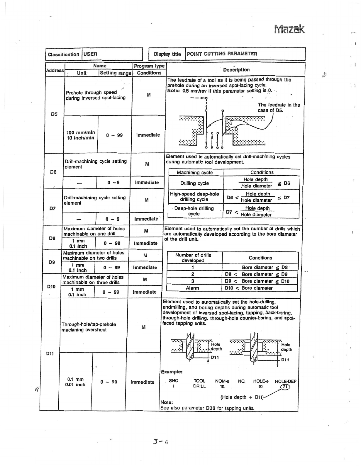
The
feedrate
prehole
Note:
during
03
automatic
Machining
Drilling
High-speed
drilling
Deep-hole
used
automatically
the
drill
Number
developed
used
tapping
CUTTING
POINT
of
tool
a
an
mm/rev
I
fin
©
cycle
unit.
of
1
2
3
and
of
drilling,
units.
to
cycle
deep-hole
cycle
to
to
inversed
automatically
tool
cycle
drilling
automatically
developed
drills
automatically
boring
used
Alarm
Description
as
it
inversed
parameter
this
if
o
o o
development.
D@
D7
D8
D9
D10
depths
spot-facing,
through-hole
PARAMETER
passed
being
is
spot-facing
.vX
set
<
<
set
according
<
<
<
set
during
cycle.
setting
drill-machining
Conditions
depth
Hole
Hole
diameter
Hole
diameter
Hole
Hole
Hole
diameter
the
number
to
Conditions
diameter
Bore
Bore
diameter
diameter
Bore
diameter
Bore
hole-drilling,
the
automatic
tapping,
counter-boring,
through
is
0.
The
feedrate
case
of
depth
depth
of
the
bore
back-boring,
05.
drills
g
g
g
tool
and
the
in
cycles
<
D6
s
D7
which
diameter
D8
D9
Dio
spot¬
the
£
I
i
i
!
I
h
;.....}.depth
D11
/
\
Example:
0.1
0.01
mm
inch
0-99
Immediate
if
3-
Note:
See
6
SNO
1
also
TOOL
DRILL
parameter
D30
SCOT:
D11
NOM-0
10.
for
(Hole
tapping
NO.
depth
units.
HOLE-0
Dll)
+
10.
Hols
depth
011
HOLE-DEP
£f£>
i
Page 11
hlciZdk
Classification
Address
Unit
USER
Name
[Setting
Program
range
Display
type
Conditions
Element
during
boring
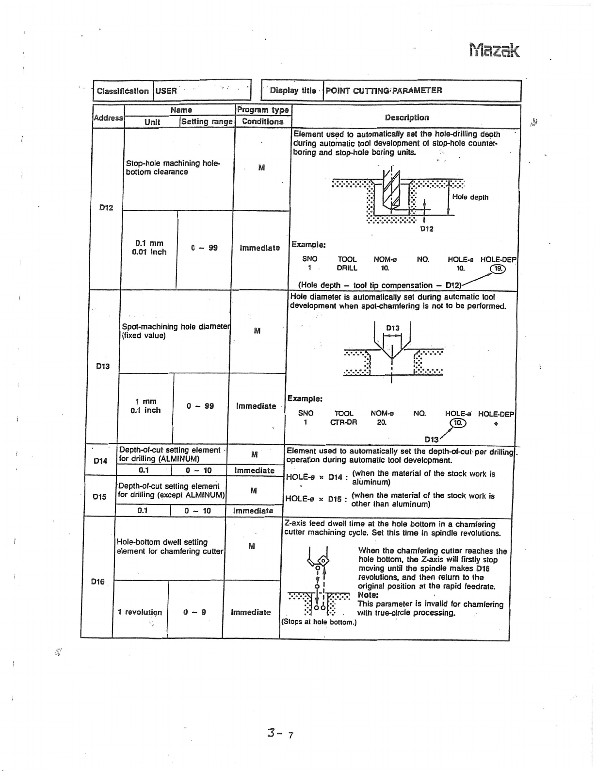
Stop-hole
!
bottom
machining
clearance
hole-
M
title
POINT
used
automatic
stop-hole
and
CUTTING'
automatically
to
development
tool
boring
PARAMETER
Description
the
set
of
units.
f
/:
hole-drilling
stop-hole
£
depth
counter-
%
Hole
depth
D12
;ÿ
«
D12
mm
0.1
inch
0.01
i
Spot-machining
(fixed
value)
hole
0-99
diameter
Immediate
M
D13
I
mm
0.1
1
inch
0-99
Immediate
Example:
SNO
1
(Hole
depth
Hole
diameter
development
Example:
SNO
1
TOOL
DRILL
-
is
when
TOOL
CTR-DR
NOM-a
10.
compensation-D12)
tip
tool
automatically
spot-chamfering
NOM-s
20.
set
NO.
during
I:-':
I
NO.
is
automatic
to
not
HOLE-0
HOLE-o
10.
performed.
be
HOLE-DEP
<3E>
tool
HOLE-DEP
o
D13
Depth-of-cut
drilling
for
D14
Depth-of-cut
for
D15
I
drilling
Hole-bottom
element
D16
1
revolution
I
i
0.1
0.1
for
setting
setting
|
dwell
element
0-10
element
ALMINUM)
0-10
setting
0-9
(ALMINUM)
(except
chamfering
cutter
M
Immediate
M
Immediate
M
Immediate
Element
operation
HOLE-s
HOLE-a
Z-axis
cutter
(Stops
used
during
x
x
feed
machining
i
.1
I
K\-
at
hole
to
014
D15
dwell
7?
bottom.)
automatically
automatic
,he
(when
•
‘
aluminum)
,he
(whan
•
other
than
timeatthe
cycle.
Set
When
bottom,
hole
moving
revolutions,
original
Note:
parameter
This
with
true-circle
set
tool
material
material
aluminum)
hole
this
chamfering
the
until
and
position
depth-of-cut-
the
development.
of
the
of
the
bottom
spindle
time
in
the
Z-axis
spindle
the
then
return
the
at
is
invalid
processing.
stock
stock
a
in
cutter
will
rapid
makes
for
per
work
work
chamfering
revolutions.
reaches
firstly
stop
D1G
to
the
feedrate.
chamfering
drilling
is
is
the
3-
7
Page 12
Mazak
Classification
Address
Interference
chamfering
D17
Return
dr
0.1
0.01
boring
USER
Unit
mm
inch
feedrate
(cycle
Name
|
Setting
clearance
cutter
for
3)
0
-
reaming
range
of
99
Program
Conditions
M
Immediate
M
Display
type
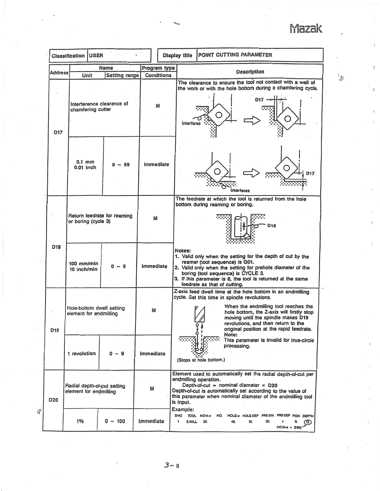
The
bottom
title
The
the
work
Interferes
feedrate
POINT
clearance
or
v.
during
CUTTING
to
with
o
at
which
reaming
ensure
hole
the
s
v
Interferes
the
or
PARAMETER
Description
contact
not
tool
the
bottom
during
017
=£>
returned
is
tool
boring.
=171
\vfc
;•
a
K
from
Dia
with
a
chamfering
o
:::
the
wall
hole
cycle.
D17
j
of
D18
mm/mln
D19
D20
100
inch/min
10
Hole-bottom
element
revolution
1
Radial
depth-of-put
element
for
dwell
for
endmilling
endmilling
0-9
setting
0-9
setting
Immediate
M
Immediate
M
(f
1%
0
100
-
Immediate
Notes:
Valid
1.
only
reamer
2.
3.
Z-axis
cycle.
Valid
boring
If
this
feedrate
feed
Set
only
V
(l
Y.v.‘
(Stops
at
Element
endmilling
Depth-of-cut
this
is
Example:
SNO
used
Depth-of-cut
parameter
input.
TOOL
1
E-MILL
when
(tool
when
(tool
sequence)
parameter
as
that
dwell
this
time
V,
•i
bottom.)
hole
to
operation.
automatically
is
when
NOM-a
setting
the
sequence)
setting
the
0,
is
the
cutting.
of
at
time
the
spindle
in
When
hole
moving
revolutions,
original
Note:
This
processing.
automatically
nominal
=
nominal
NO.
HOLE
4a
for
G01.
is
for
CYCLE
is
tool
_
hole
revolutions.
endmilling
the
bottom,
until
position
parameter
set
diameter
according
set
diameter
-a
HOLE-OEP
10.
the
prehole
3.
is
returned
bottom
the
the
and
the
depth
Z-axis
spindle
then
the
at
invalid
is
radial
x
D20
the
of
PRE-OIA
3a
of
cut
diameter
the
at
an
in
endmilling
tool
reaches
will
makes
return
rapid
for
depth-of-cut
to
the
endmiiling
PHE-OEP
(NOM««
by
the
of
the
same
firstly
D19
to
the
feedrate.
true-circle
of
value
HGH
DEPTH
Q
»
020)*ÿ
the
stop
per
tool
®
3-8
Page 13
Classification
USER
Display
title
POINT
CUTTING
Mazak
PARAMETER
M
M
M
type
reference
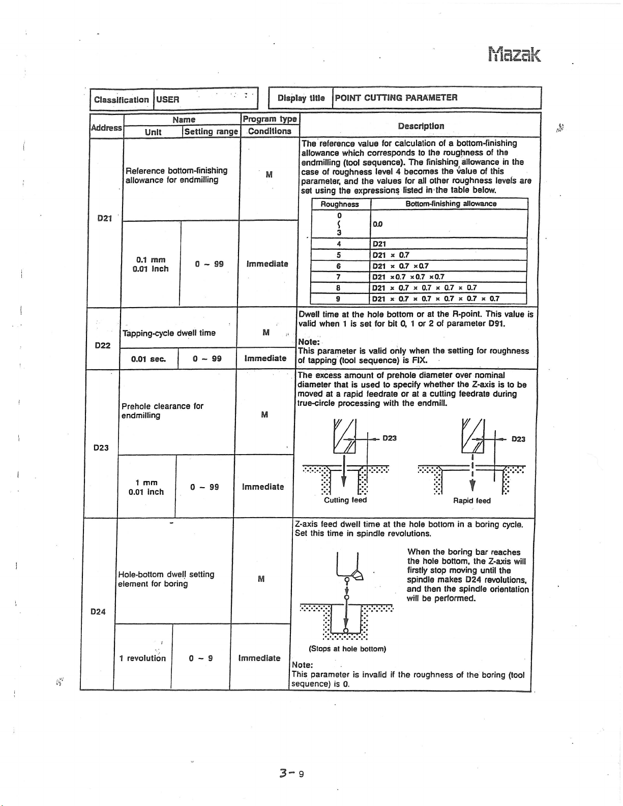
The
allowance
endmilling
of
case
parameter,
using
set
Roughness
Dwell
time
valid
when
Note:
parameter
This
tapping
of
The
excess
diameter
moved
at
true-circle
Culling
value
which
(tool
roughness
and
expressions
the
0
4
5
6
7
8
9
the
at
1
set
is
is
(tool
sequence)
amount
is
that
rapid
a
processing
w
£
V
feed
for
corresponds
sequence).
level
values
the
OJD
D21
D21
*
*0.7
021
bottom
hole
bit
for
only
valid
prehole
of
to
used
feedrate
with
Description
calculation
to
The
becomes
4
all
for
listed
Bottom-finishing
»
0.7
*a7
ar
K
0.7
x
0.7x0.7
x
x
0.7
or
0,
or
1
when
FIX.
is
diameter
specify
or
at
endmill.
the
of
the
finishing
other
the
in1
KQ.7
x
x
0.7
at
the
2
of
the
whether
cutting
a
bottom-finishing
a
roughness
allowance
value
the
roughness
table
below.
allowance
x
0.7
0.7
x
0.7
0.7
R-point.
parameter
setting
for
over
nominal
the
Z-axis
feedrate
r
A
a
?
Rapid
feed
of
this
of
levels
x
0.7
This
D91.
roughness
during
the
is
I
in
value
to
$
the
are
is
be
D23
Address
Reference
!
allowance
Unit
bottom-finishing
for
Name
|
Setting
endmiiiing
range
Program
Conditions
D21
mm
D22
D23
0.1
inch
0.01
Tapping-cycle
sec.
0.01
0.01
1
clearance
mm
inch
Prehole
endmilling
dwell
0-99
time
0-99
for
0-99
Immediate
Immediate
Immediate
Z-axis
feed
dwell
Set
this
time
setting
Hole-bottom
element
for
dwell
boring
U
y.
3“
(Stops
Note:
parameter
This
sequence)
9
1
revolution
0-9
Immediate
if
spindle
in
u
at
hole
is
is
0.
timeatthe
:::
bottom)
invalidifthe
hole
revolutions.
When
the
firstly
spindle
and
will
roughness
hole
then
be
bottom
boring
the
bottom,
stop
moving
makes
the
performed.
in
a
D24
spindle
of
the
boring
bar
reaches
the
Z-axis
until
revolutions,
orientation
boring
cycle.
will
the
(tool
Page 14

Mazak
i
Classification
Address
Boring-bar
D25
Boring
bottom
D26
0.1
0.01
USER
Unit
mm
inch
back-boring
or
return
Name
[Setting
tip
relief
0-99
range
hole-
Program
Conditions
M
Immediate
M
Display
type
title
The
kept
Notes:
Valid
1.
boring
For
2.
of
The
same
hole
::j:
'
POINT
amount
clear
During
only
(tool
the
bit
3
distance
feedrate
bottom.
!
of
X
relief
and
S:
CUTTING
of
relief
the
hole
boring
when
sequence)
direction
4
bit
boring
the
as
that
provided
wall
setting
the
114.
of
existing
PARAMETER
Description
for
spindle
after
for
CYCLE
is
tool
of
the
back-boring
or
after
'
!
f
the
the
:::
1.
tip,
the
"
tip
of
a
orientation.
!*
.
During
prehole
see
the
is
tool
tool
has
026
boring
H+—
-
CvX
-
B
0
B
returning
diameter
description
returned
reached
L-Kd
bar
D2S
!$
I
,
|
»
to
of
the
at
the
the
ZT77-
be
!
$
i
the
at
D28
original
tool
@
the
of
of
70%
of
the
to
complete
positioned
Returned
rapid
feedrate.
boring
the
original
value
boring
at
at
(tool
before
(tool
chip
a
the
a
i
D27
Q.1
mm
inch
0.01
Bottom-finishing
boring
0-99
amount
of
Immediate
M
Has
©
hole
Note:
Not
valid
sequence)
Invalid
The
distance
feedrate
reached
bottom.
to
if
is
finish
the
1.
the
the
setting
_
boring
the
©
hole
v.;.y-
Returned
same
the
for
bar
bottom.
feedrate.
roughness
is
fed
I
-fCyy.o
il
at
in
I
D2S
The
feedrate
hole
0.1
0.01
mm
Inch
0-99
immediate
(f
D29
Chip
removal
1
sec.
time
0-99
M
Immediate
the
Note:
Not
valid
sequence)
The
time
removal
hole
bottom.
is
bottom
if
the
is
1.
required
operation
reduced
is
reached.
setting
for
after
to
70%
for
the
chip
a
the
tool
of
roughness
removal
has
the
been
Page 15

Mazsk
Classification
Address
Number
threads
Tapper
tap
1
Unit
thread
USER
Name
incomplete
of
tapping
in
elongation
|Setting
cycle
0-9
amount
range
of
Program
Conditions
M
Immediate
M
Display
type
Set
title
Element
during
Example:
SNO
1
Hole
f
Excess
during
this
POINT
used
automatic
depth
amount
a
tapping
value
R-point
CUTTING
automatically
to
tool
TOOL
DRILL
D11
-f
of
tool
cycle.
spindle
in
-f
PARAMETER
Description
development
;
X
%-
fp
NOM-a
10.
(D30
+
return
due
revolutions.
«
set
:::
pitch)
the
hole-drilling
for
tapping
j
Hole
-
D30
,
NO.
l
elongation
to
D31
depth
K
Pitch
HOLE-e
10.
Pitch
*
depths
unit.
HOLE-DEP
of
the
&
19?
tapper
revolution
1
0-9
Immediate
SI
Number
until
beginsintapping
revolution
1
Back-boring
D33
!
0.1
0.01
D34
of
spindle
mm
inch
spindle
CCW
tool
revolutions
rotation
_
cycle
0-99
tip
relief
0-99
M
Immediate
M
Immediate
The
has
spindle
rotation.
The
kept
the
prehole
©
Note:
For
the
bit
3
Invalid
number
rotated
CCW
amount
clear
During
relief
and
bit
inertial
of
clockwise
rotation
relief
of
the
of
in
the
back-boring
direction
4
of
prehole
oriented
I
114.
turns
during
command
provided
walls
state
iii
the
of
in
the
tool
tapping
time
to
for
a
as
of
tip,
it
cycle
output
from
the
start
back-boring
being
is
spindle.
the
k
!
0
0
During
©
see
the
that
the
of
of
spindle
tool
passed
-=>-
-i
r.-.v.1
.
\\
m,
passage
description
spindle
a
CCW
tip
to
through
D33
of
be
i
3-
11
Page 16
Mazak
i
Classification
Address
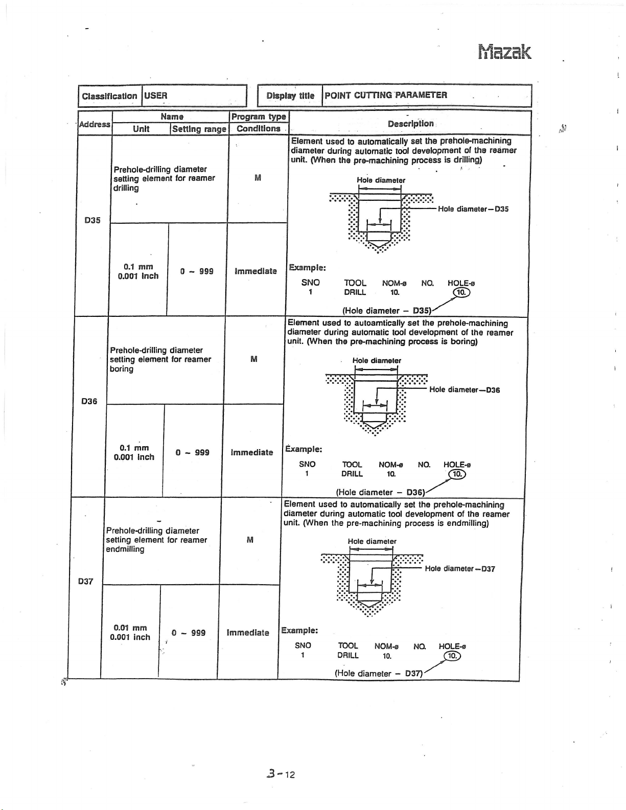
Prehole-driliing
setting
drilling
D35
0.001
Prehole-drilling
setting
boring
D36
0.1
USER
Unit
element
mm
Inch
element
Name
|
Setting
diameter
for
diameter
for
reamer
0
-
reamer
range
999
Program
Conditions
M
Immediate
M
Display
type
diameter
title
Element
diameter
(When
unit.
Example:
SNO
1
Element
(When
unit.
POINT
used
during
the
used
during
the
CUTTING
automatically
to
automatic
pre-machining
Hole
diameter
TOOL
DRILL
(Hole
diameter
autoamtically
to
automatic
pre-machining
Hole
diameter
Li
PARAMETER
Description
tool
rrÿ
JL_j
•••
NOM-o
10.
-
set
development
tool
process
prehole-machining
the
set
development
process
D35)
is
Hole
NO.
the
prehole-machining
is
Hole
of
the
drilling)
b
diameter—
HOLE-®
10.
of
the
boring)
diameter—
reamer
D35
reamer
D36
i
D37
mm
0.1
inch
0.001
Prehole-drilling
setting
element
endmilling
0.01
mm
0.001
inch
0
-
diameter
reamer
for
0
-
999
999
Immediate
M
Immediate
Example:
SNO
1
Element
diameter
(When
unit.
Example:
SNO
1
used
during
the
TOOL
DRILL
(Hole
diameter
to
automatically
automatic
pre-machining
Hole
diameter
£
H
4S
TOOL
DRILL
(Hole
diameter
NOM-s
H
r*;
NOM-0
10.
10.
-
set
tool
X
-
NO.
D36)-
the
prehole-machining
development
process
D37)
NQ
is
Hole
HOLE-®
HOLE-e
10.
of
the
endmilling)
diameter—
10.
reamer
037
!
i
3-12
Page 17
Md£ok
Display
type
Conditions
M
0.01
0.001
Unit
element
mm
inch
USER
Name
|
Setting
diameter
for
0
boring
999
-
Program
range
or
Immediate
Classification
Address
)
i
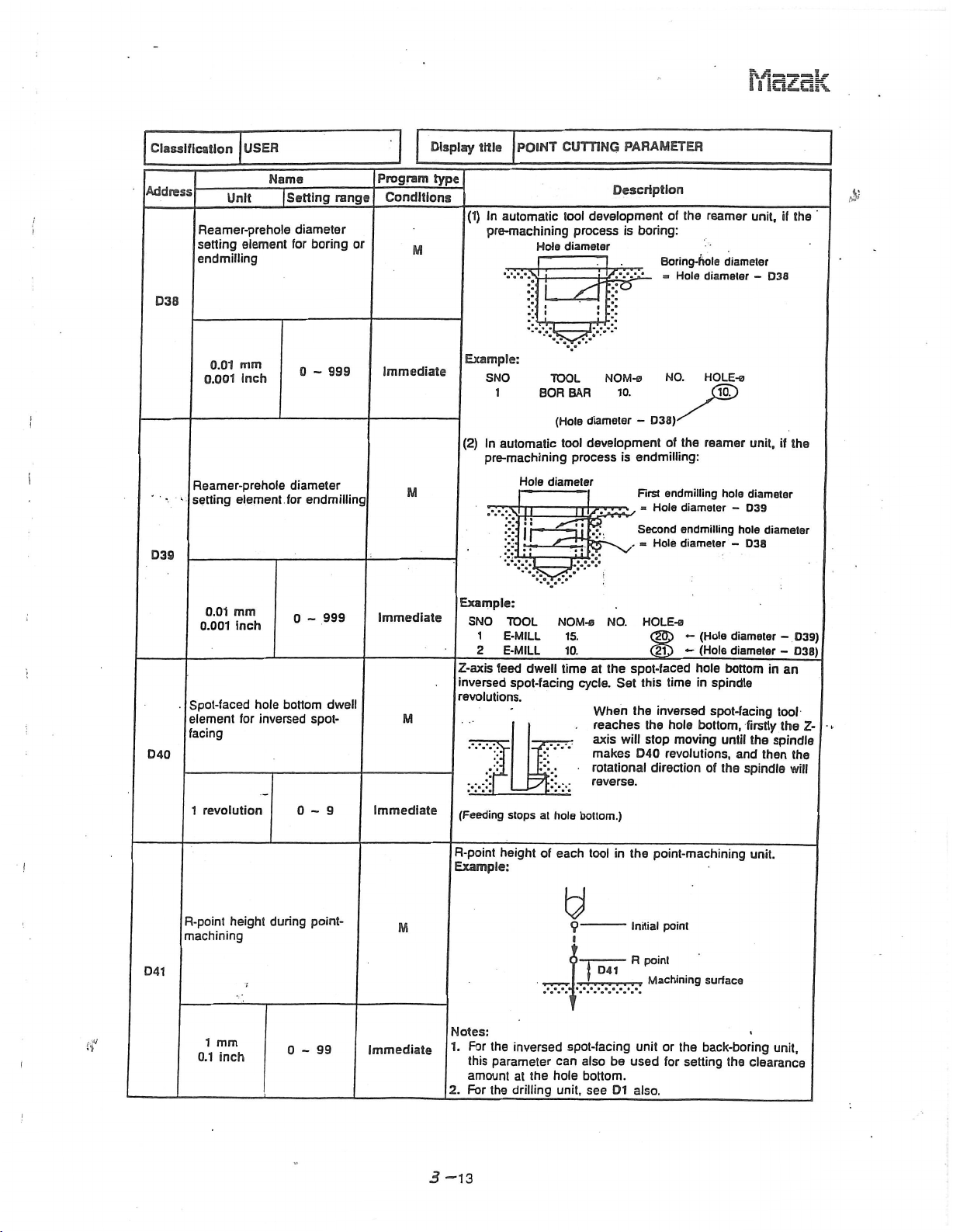
Reamer-prehole
setting
endmilling
D3S
I
D39
Reamer-prehole
setting
element
diameter
endmilling
for
M
title
In
(1)
automatic
pre-machining
Example:
SNO
1
(2)
In
automatic
pre-machining
i
CUTTING
POINT
tool
process
diameter
Hole
I
TOOL
BAR
BOR
(Hole
tool
process
Hole
diameter
mz
PARAMETER
Description
development
diameter
development
l/y.-AL
c
:
NOM-0
10.
boring:
is
-
endmilling:
is
First
Second
«
Soring-hola
-
D38)-
»
Hole
Hole
the
of
Hole
NO.
the
of
endmilling
diameter
endmilling
diameter
reamer
diameter
diameter
HOLE-e
10.
reamer
hole
-
-
unit,
-
unit,
diameter
D39
hole
D38
if
D38
if
the
diameter
$
the
mm
0.01
0.001
inch
999
0
-
immediate
:>
Spot-faced
D40
D41
element
facing
revolution
1
R-point
machining
1
0.1
!
t?
i
mm
inch
for
height
hole
inversed
during
bottom
0-9
0-99
dwell
spot¬
point¬
M
Immediate
M
Immediate
Example:
SNO
TOOL
1
E-MILL
2
E-MILL
Z-axis
feed
inversed
revolutions.
dwell
spot-facing
JUT
For
the
this
parameter
amount
For
the
stops
height
inversed
at
drilling
the
at
hole
of
hole
(Feeding
R-point
Example:
Notes:
1.
2.
NOM-s
15.
10.
at
time
cycle.
bottom.)
tool
each
Q
?
9
spot-facing
can
also
bottom.
unit,
see
NO.
spot-faced
the
Set
When
reaches
axis
will
makes
rotational
reverse.
the
in
D41
be
D1
HOLE-0
ap
>
<
&0
-
this
time
the
inversed
the
hole
stop
moving
revolutions,
D40
direction
point-machining
point
Initial
point
R
Machining
or
unit
the
for
_
setting
used
also.
(Hole
-
(Hole
hole
spindle
in
spot-facing
bottom,
until
of
the
surface
back-boring
diameter
diameter
bottom
firstly
the
and
spindle
the
clearance
unit.
in
tool
spindle
then
unit,
-
-
an
the
D39)
038)
Z-
the
will
3
-13
Page 18

Mazak
Classification
Address
D42
D46
Reamer-prehole
overshoot
D47
0.01
0.001
D48
D90
Unit
mm
inch
USER
Name
|
Setting
machining
Display
Program
range
999
0
-
Conditions
Immediate
type
Invalid
Element
endmilling
the
M
Example:
Invalid
title
reamer
•y.\\
SNO
1
POINT
used
and
unit.
For
drilling
TOOL
DRILL
automatically
to
boring
(Hole
CUTTING
during
Hole
D47
NOM-fl
10.
depth
Description
depth
PARAMETER
set
hole
the
automatic
For
endmilling
NO.
HOLE-a
D47)
+
depth
tool
development
•!•!
!
10.
of
drilling,
depth
|Hole
D47
or
boring
HOLE-DEP
-(S)
I
£
l
of
i
D91
Bit
Binary
digits
eight
M
Immediate
L
_
_
_
_
I
I?
L.M04
dwelled
tapping
_
The
output
tapping
The
returned
tapping
The
during
(endmilling).
__The
true-circle
(chamfering).
.The
as
Execution,
(1:
is
tool
tool
finishing
tool
R-point
D1.
output
at
cycle.
at
cycle.
dwells
cycle.
true-circle
a
path
after
hole
the
dwells
after
the
hole
after
R-point
to
the
tool
is
shortened
processing
height
0:
No
the
bottom
M04
bottom
it
path
processing
cycle
of
the
execution)
tool
has
during
has
during
has
been
during
is
shortened
during
drill
is
been
a
cycle
set
a
a
i
a
if
I
3-
14
Page 19
Mazak
Classification
Address
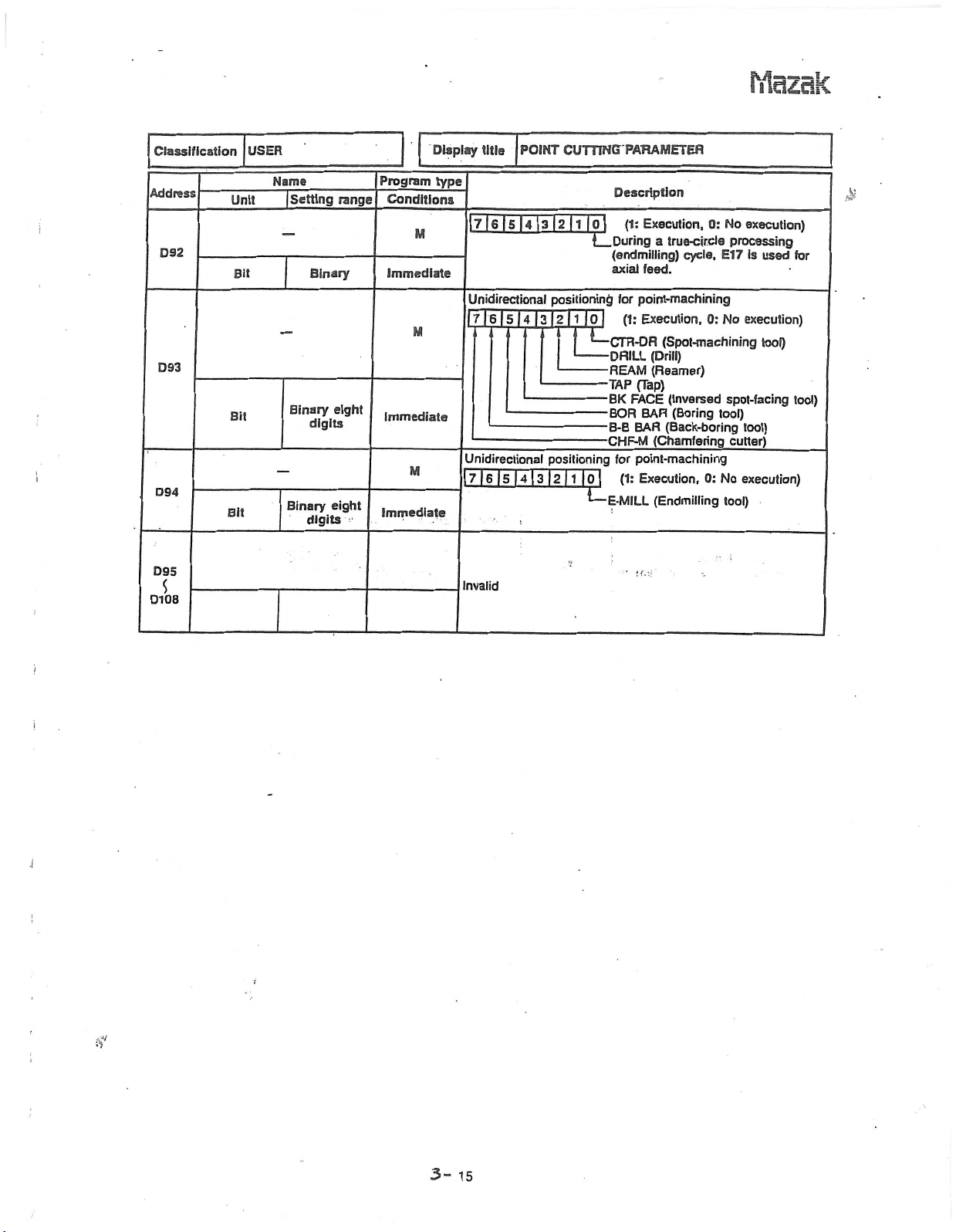
D92
D94
D
95
D108
Unit
Bit
Bit
Bit
USER
Name
|
Setting
Binary
Binary
Binary
digits
digits
range
eight
eight
Program
Conditions
M
Immediate
M
Immediate
M
Immediate
Display
type
|7|6|5l4|3|2|l
Unidirectional
|7|6|5|4|3|2|1
Unidirectional
7
Invalid
title
|6|5|4
POINT
positioning
|2
[3
CUTTING
|0|
L_
positioning
|ol
*
f
—
1
-
|0~l
M
PARAMETER
Description
Execution,
(1:
During
a
(endmilling)
feed.
axial
point-machining
for
Execution,
(1:
Cm
DRILL
REAM
TAP
BK
BOR
B-B
CHF-M
for
E-MILL
(Spot-machining
-DR
(Drill)
(Reamer)
(Tap)
FACE
BAR
(Back-boring
BAR
(Chamfering
point-machining
Execution,
(1:
(Endmilling
'*
r.
:.i
i
0:
true-cir.cle
cycle,
0:
(Inversed
(Boring
0:
No
execution)
processing
is
E17
used
No
execution)
tool)
spot-facing
tool)
tool)
cutter)
No
execution)
tool)
•;
£
for
tool)
!
J
3-
15
Page 20
ffidZik
i
Classification
Address
Closed-pattern
point
setting
El
0.01
Cutting
escape
0.1
Unit
and
element
mm
inch
start
point
USER
escape
point
Name
|Setting
cutting
setting
point
0
-
and
element
range
start
999
Program
Conditions
M
Immediate
M
Display
type
[Applicable
Element
for
Example:
title
Element
for
closed-pattern
Example:
>MM
LINE
•
OUT.
8
Wall
finishing
line-
Tool
diameter/2
Cutting
point
start
Tool
diameter
LSNE/FACE/3-D
set
to
used
the
line-
sfsi
LINE
of
to
g
Cutting
start
IN,
STEP,
set
the
Removal
E1
units]
used
or
face-machining.
eg
£2
Removal
<
CUTTING
Description
cutting
face-machining.
or
•
»
point
CHMF
OUT
POCKET,
cutting
allowance-R
Removal
allowance-R
start
start
PAH
point
.Escape
point
CHMF
and
PCKT
point
allowance-R
and
MT
and
escape
w-
IN
and
escape
El
PCKT
Escape
point
point
VLY
point
i
£
i
l
3?
E2
0.1
0.01
mm
inch
Removal
[Applicable
®
0
999
~
immediate
All
Face-machining
•
units]
line-machining
units
units
other
than
SLOT
FACE
allowance-R
MIL,
TOP
EMIL,
and
Notes:
1:
See
the
E3
2:
Positioning
E9S,
Invalid
but
diagram
of
only
parameter
of
the
at
E2
line-machining
for
escape
E1
point
also.
units.
can
be
selected
using
i
i
*
if
J
“
16
Page 21

Mazak
Classification"
Address
Reference
radial
in
E4
0.1
0.01
E5
Reference
axial
in
USER
Unit
direction
mm
inch
direction
Name
|Setting
allowance
allowance
of
when
have
R
of
below.
OO
E4
x
E4
x
E4
x
E4
x
E4
x
E4
CUTTING
Description
each
roughness
the
been
the
in
parameter,
this
are
calculated
0.7
x
0.7
x
0.7
x
0.7
0,7
X
Display
Program
range
of
0
999
-
Conditions
finish
Immediate
type
M
title
LINE/FACE/3-0
The
reference
automatically
face-machining
The
finish
becomes
other
listed
allowance
the
roughness
in
the
Roughness
0
1
3
4
S
6
7
8
9
table
value
set
units
value
levels
PAR
Finish
allowance
levels
set.
roughness
of
case
and
using
Finish
allowance
0.7
x
0.7
0.7
0.7x0.7x0.7
0,7
X
X
0.7
0.7
the
the
x
R
which
the
of
level
values
expressions
R
0.7
line-
for
is
or
4
all
Invalid
of
finish
The
reference
automatically
face-machining
The
finish
M
becomes
other
listed
allowance
the
roughness
in
the
table
value
set
units
value
of
when
of.
levels
below.
have
Z
this
in
are
each
roughness.
the
been
the
parameter,
calculated
finish
case
allowance
set.
of
levels
roughness
and
the
using
the
Z
which
of
the
level
values
expressions
line-
for
is
or
4
all
E6
E7
0.1
0.01
mm
inch
Roughness
0
5
3
4
5
999
0
-
immediate
6
7
8
9
0.0
E6
E6
E6
E6
EG
E6
x
x
x
x
X
invalid
Finish
0.7
0.7x0.7
0.7x0.7x0.7
x
x
0.7
0.7
0.7
X
0.7
0.7
X
0.7x0.7
allowance
x
0.7
Z
x
0.7
I
tf
I
3-
17
Page 22

frlazak
Classification
Address
Radial
of
E8
Allowance
start
E9
0.01
USER
Unit
interference
chamfering
0.1
mm
inch
0.01
position
0.1
mm
Inch
Name
Setting
cutter
axial-cutting
of
0
clearance
0
-
999
-
range
999
Program
Conditions
M
Immediate
M
Immediate
Display
type
work
Example:
title
The
amount
chamfering
Interferes
Element
axial
direction
ing
tool
has
a
at
UNE/FACE/3-D
of
clearance
with
cutter
/
Interference
used
rapid
to
is
been
distance
set
the
be
to
moved
feedrate.
YA
t
'.•.T.,.w.vX,.v,
CUTTING
Description
that
hole
the
position
started
from
Initial
ES
PAR
ensures
walls
<>
which
in
the
after
initial
the
point
Removal
no
during
the
line-
point
allowance
interference
E8
ilr
mo
or
of
the
face-machining.
I
cutting
feed
face-machin¬
toward
Z
in
the
&
i
.
I
t
i
l
E10
E11
Depth-of-cut-R
element
setting
Endmilling-top,
relief)
10%
Axial
interference
of
chamfering
0.1
mm
inch
0.01
automatic
(Face
Endmilling-
0-9
clearance
cutter
5-40
milling,
M
Immediate
M
Immediate
Element
Radial
SNO
HI
sequence
tool
TOOL
F-MILL
amount
the
Example:
The
chamfering
Interference
to
used
depth-of-cut
NOM-o
1CX1A
of
clearance
automatically
cutter
o
depth
in
NO.
with
FACE
=
APBCHJt
? ?
the
Interferes
set
MIL,
TOP
Nominal
that
hole
diameter
APRCH-Y
ensures
bottom
U=£>
the
10
TYPE
Nominal
radial
EMIL
XSI
diamotcf
no
interference
during
depth-of-cut
or
STEP
E10
><
ZFD
DEM
u
E10
10
chamfering.
oBo
a
o
a'i
of
unit.
W1D-H
TO
I.
(he
of
i
Ell
tKi'
i
i
l
J
if
1
3-18
Page 23

Classification
USER
Mazak
.ÿ
i
'
Display
UNE/FACE/3-D
title
CUTTING
PAH
Address
E12
E13
E14
Unit
interference
Radial
milling
face
of
mm
0.1
inch
0.01
path
Tool
endmilling-top
10%
Depth-of-cut-R
setting
element
milling.
Pocket
milling-hollow)
Pocket
10%
path
Tool
face
(reciprocating
setting
milling
Name
|
Setting
unit
setting
unit
automatic
(Pocket
milling-relief,
element
unit
short)
clearance
0
-
element
1
-
0-9
range
999
9
for
for
Program
Conditions
M
Immediate
M
Immediate
M
Immediate
M
type
The
the
Example:
Element
endmilling-top
Example:
Tool
Element
the
Example:
SNO
m
Element
figure
Example:
amount
tool
and
Escape
o-
o-
Cutting
start
point
used
diameter
used
sequence
tool
depth-of-cut
Radial
TOOL
NOWLo
ZOA
EMILL
used
for
reciprocating-short
clearance
of
figure
the
point
E12
to
set
unit.
E3
x
-
10
automatically
to
in
NO.
APRCH-X
to
set
the
Description
that
during
-
L
path
tool
the
O
POCKET.
Nominal
»
APHCH-Y-
?
path
tool
machining
ensures
face
Defined
internal
Defined
the
set
PCKT
7
external
no
milling.
figure
E12
t
Tool
radial
MT
diameter
10
TYPE
cw
Nomina]
with
contact
to
the
diameter
figure
depth-of-cut
or
PCKT
x
ZFD
GOT
die
roefof
10
to
the
face
-i
figure
E14
OEP-Z
n
E14
defined
milling
between
x
VLY
-WIOÿ
ia
for
_
Etg
10
of
unit.
1?
unit.
&
’
Tool
-
©
diameler
E1S
x
-
10
E15
o
i
10%
9
1
-
immediate
3-
Tool
19
diameter
x
10
Defined
7
figure
Page 24

Mazak
Classification
Address
Peripheral-cutting
override
unit
E16
Axial-cutting
E17
USER
Unit
endmilling-relief
for
feedrate
Name
Setting
I
feedrate
1
-
override
range
20
Program
Conditions
M
Immediate
M
Display
type
Override
endmilling-relief
the
Note:
Valid
Example:
Tool
feedrate
Override
face-machining
moved
Notes:
1.
2.
Example:
title
LINE/FACE/3-D
valueofihe
work.
only
when
sequence
x
value
to
the
Valid
only
Feed
overriding
unit
bit
E16
of
unit
machining
when
idle-cutting
is
of
0
feedrate
the
(excluding
ZFD
is
invalid
u
i
CUTTING
Description
moved
be
to
E91
is
H
at
face
surface
sequence
tool
of
when
feedrate
and
1
which
in
this
PAR
around
bit
milling
an
axial
parameter
7
figure
the
is
which
at
the
is
0.
Tool
feed
tool
of
unit)
is
direction.
G01.
outer
a
to
is
tool
of
form
sequence
rate
or
line-
be
0.
.
.
&
of
I
i
l
i
i
Pocket-machining
width
E18
10%
override
10%
0-9
across-the-
0-9
Immediate
M
Immediate
Tool
sequence,
_
.
w
leedrale
Override
which
equal.
E17
.
*
10
valueofthe
the
pocket-machining
.
£1
Note:
Across-the-width
is
0.
[Applicable
Rough-machining
STEP
units]
tool
overriding
POCKET,
of
diameter
radial
Tool
not
is
PCKT
E9
8
(across-the-width)
depth-of-cut
sequence
valid
MT,
when
PCKT
feedrate
this
Removal
allowance
*
Machining
"•
surface
becomes
parameter
VLY
and
Z
to
g
_
Ei
x
10
i
3“
20
Page 25

Ftick.dk
i
Classification
Address
E19
E20
Wall-cutting
figure
E21
0.01
0.1
Unit
mm
inch
USER
Name
|
Setting
overlap
Program
range
in
closed
0
999
-
Immediate
Display
Conditions
M
i
of
Override
corner
value
overriding
automatic
/
M
type
title
Invalid
The
amount
in
closed-pattern
Example:
Escape
[Applicable
OUT,
LINE
°
Wall
hnishing
•
SLOT
Override
machining
Example:
Tool
LINE/FACE/3-D
overlap
of
point
units)
LINE
of
valueofautomatic
sequence
teed
rate
line-
Defined
IN,
STEP,
or
CHMF
E22
100
CUTTING
Description
of
the
face-machining.
closed
PAR
wall-cutting
pattern
:SE2?5»SS®,
OUT
comer
and
PCKT
overriding
POCKET,
'
!ÿ
-
start
9
jCutting
CHMF
MT,
and
IN
PCKT
in
line-
Tool
feed
end
point
start
VLY
or
sequence
rate
areas
and
face-
E22
Note:
1%
Effective
(upper
corner
E23
I
Effective
(lower
corner
E24
tf
removal
limit)
overriding
1%
removal
limit)
overriding
1%
of
automatic
of
automatic
0-99
allowance
99
1
-
allowance
99
1
-
Immediate
M
Immediate
M
Immediate
Automatic
is
0.
[Applicable
RGT,
LINE
PCKT
MT
The
range
The
automatic
following
[Removal
line-
Tool
diameter
allowance]
Removal
Machining
Line-roughmachining
Face-roughmachining
corner
units]
LINE
and
of
removal
corner
or
E24
x
x
100
allowance
PCKT
overriding
LFT,
face-machining
<
=
is
OUT,
LINE
VLY
allowances
overriding
Removal
allowance
invalid
LINE
(upper
becomes
conditions
<
-
(Radial
(Radial
-
(Radial
when
IN,
and
Tool
diameter
f
Removal
removal
this
parameter
STEP,
POCKET.
lower
valid
when
are
met:
E23
*
100
allowance
allowance)
allowance)
finish
depth-of-cut)
limits).
the
J-
21
Page 26

Classification
USER
Display
LINE/FACE/3-0
title
CUTTING
Mazak
i
PAR
Address
E25
E26
$
£54
Effective
automatic
of
overriding
3-D
cutting-feed
Axial
Unit
r
angle
Name
|Settlng
(upper
corner
1
overriding
range
limit)
Program
Conditions
type
shape
The
The
automatic
following
line-
Shape
angle
corner
face-machining
or
angle
range
g
Description
(upper
overriding
E25
angle
Shape
limit).
becomes
conditions
valid
are
when
met:
the
£
I
\
w
179
-
Immediate
M
Invalid
Feed
overriding
a
3-D
unit.
Example:
for
cutting
Tool
a
work
sequence
rate
feed
an
in
axial
jss.
direction
y
10
using
iH
E55
E56
10%
3-D
Inversion
surface
check
pattern
of
-9
0
curved-
1
0,
Immediate
M
Immediate
High-speed
Note:
overriding
Feed
The
parameter
message
pattern
becomes
0:
No
1:
Alarm
Example:
The
curved
pattern
points
Note:
parameter
This
processing.
is
to
be
points
in
impossible).
alarm
surface
in
is
rough
is
invalid
used
displayed
the
the
invalid
processing
to
select
-Z
defined
of
a
-Z
during
Depth-o(-cut
when
whether
if
the
direction
direction.
Finish
parameter
this
or
curved
(normally,
high-speed
S5
processing
an
not
surface
processing
rough
is
0,
alarm
of
I
a
defined
ES9
I
i
i
i
3-22
Page 27

r£.S
<?M*
P
X
<5-
A\
<v
6
<
o?
/
x
$
VN
X
QJD
c>ÿ
/
‘
Mazak
v—
"XMo-0
CUTTING
to
select
accordance
is
no?
strictly
is
invalid
is
time
becomes
select
to
according
a
of
made
position
the
started
toward
E59
;.j
high-speed
_
(cutting)
to
Description
defined
the
the
type
Element
axial
from
Example:
Material
The
of
curved
Example:
Mis'
L1NE/FACE/3-0
parameter
The
performed
be
pitch
data
The
0:
The
1:
Notes:
This
1.
processing.
The
2.
to
1.
parameter
The
diameter
for
the
0:
Diameter
1:
Diameter
Example:
Diameter
direction
the
in
setting.
pitch
pitch
setting
parameter
operation
compensation
curved
surface
compensation
compensation
compensation
used
to
istobe
point
initial
y
i
s
height
i
$*x*F:**m
Normal-speed
rough
processing
finish
surface.
EGO
processing
with
the
3-D
normal
used
strict
setting
used
set
Work
or
respect
Display
Conditions
M
Immediate
M
M
M
0.1
0.01
USER
Unit
check
position
mm
inch
cutting
Name
|
Setting
of
compensation
axial-cutting
of
0
allowance
cutting
0,
0,
1
999
-
Program
range
1
Immediate
Immediate
Classification
Address
3-D
Severity
pitch
E57
3-D
Tool-diameter
ESS
3-D
Allowance
start
E59
i
3-D
Normal
E60
whether
strictly
observed.
during
long
-whether
made
not
made
Diameter
in
after
work
defined
PAR
or
with
the
observed.
high-speed
if
this
or
to
tool
pattern.
compensation
which
the
tool
a
at
Finish
allowance
pattern
;
I
'
not
processing
tool-sequence
rough
parameter
not
3-D
data
is
the
cutting
has
been
rapid
feedrate.
u
!
processing
in
the
of
EGO
tool-
to
be
n
a
•
not
feed
moved
pattern
direction
the
is
is
set
made
made
in
IE59
£
to
0.1
0.01
mm
inch
999
0
-
Immediate
3-
23
yy
Page 28

Mazak
i
Classification
Address
E61
3-D
Search
cutting
E62
3-D
Pattern
segments
E63
3-D
Pattern
segments
E64
3-D
Radial
area
ESS
0.01
3-D
Axial
area
E66
0.01
3-D
Search
cutting
0.1
0.01
0.1
0.01
check
0.1
cutting
check
mm
0.1
inch
USER
Unit
length
mm
inch
length
mm
Inch
display
display
cutting
mm
inch
Name
|
for
division
(FL
direction)
division
(GL
direction)
allowance
allowance
0
Setting
parallel
for
0
-
right-angle
0
-
0
-
0
-
0
-
999
-
999
999
for
999
S99
999
range
for
Program
Conditions
M
Immediate
M
immediate
M
immediate
M
immediate
M
Immediate
M
Immediate
Display
type
Note:
This
pattern,
from
machined.
The
which
Example:
title
The
length
nest
approximation
Depending
ESI
is
BSZ
is
The
number
curved
surface
surface
Example:
GL
or
parameter
and
the
allowance
has
E66
I
slM'
L1ME/FACE/3-D'
line
short
of
a
point
tool-sequence
on
the
applicable
applicable.
pattern
normal
thus
actual
been
segments
of
is
on
E64
to
is
the
pattern
of
cutting
set
to
the
FL
used
using
for
for
be
PATH
for
pattern
of
?
%
v
I
I
I
I
f
£
il
"
I
CUTTING
Description
segment
tool-path
.for
II-Z-,
or
/A1
_|-1
or
into
which
divided
CHECK
display
displayed
the
curved
work
a
area
the
PAR
which
determines
creation.
selected:
method
or
.
_J-2.
the
defined
display
for
of
along
check
of
display.
E63
a
curved-surface
may
slightly
the
function.
to
wall
surface
u
I
I
I
UJ
rsp
—
ESS
the
be
of
w
Max.
pattern
curved-
FL
differ
the
area
the
ES6
4*
%
1
s
of
a
j
3-24
Page 29

ffidzak
Classification
Address
3-D
Processing
E67
E75
0.01
0.001
3-D
Entire-width
E76
Unit
mm
inch
USER
error
override
Name
|
Setting
tolerance
999
0
-
range
Program
Conditions
M
Immediate
M
Display
type
title
That
processing
surface
9)
of
the
#T
Address
Example:
The
override
depth-of-cut
width
(diameter)
Example:
r
'
I
!
i
i
I
i
UNE/FACE/3-D
tool
i
«
I
1
E67
#T
in
error
which
sequenca
1
E60
value
radial
a
of
2
which
the
pattern
-n
1
,|
i
CUTTING
Description
tolerance
corresponds
3
4
E69
E70
becomes
direction
tool.
f
i
i
i
i
I
f
!
I
PAR
with
E71
respect
to
5
a
#T
6
E72
to
setting
7
E73
__
N,
#T
in
case
valid
becomes
equal
Tool-sequence
j
—
curved-
a
E74
Curved-
surface
pattern
that
to
feed
through
(1
8
the
the
entire
KE76
9
E75
10
I
10%
3-D
cutting
Radial
high-speed
(work
size
appointment)
E77
0.1
mm
0.01
inch
E78
5
(i
E82
allowance
rough
0-9
processing
999
0
-
for
Immediate
M
Immediate
Note:
Entire-width
The
clearance
appointment)
v
Invalid
overriding
of
between
S
''N
o
--
>4<
E77
is
high-speed
the
Defined
not
tool
valid
rough
and
pattern
when
this
processing
figure.
the
Work
/•\\
1
E77
_
parameter
(work
>°<
3><
-“-o
size
is
0.
3-25
Page 30

MdZdk
i
Classification
Address
3-D
Region
during
processing
appointment)
E83
0.01
3-D
Region
during
processing
appointment)
E84
0.1
0.01
Unit
mm
0.1
inch
of
high-speed
mm
inch
USER
Name
|
radial
of
high-speed
(offset
machining
axial
(offset
Setting
machining
rough
0
-
rough
0
9999
-
range
9999
Program
Conditions
M
Immediate
M
Immediate
Display
type
That
which
(offset
Example:
LINE/FACE/3-0
title
That
amount
determines
appointment),
height
Material
distance
determines
appointment)
Curved-surface
CUTTING
Description
curved-surface
a
offset
region
radial
a
from
high-speed
of
direction.
of
the
in
\
\
E83
from
the
regionofhigh-speed
the
in
TIP
E83
pattern
bottom
an
axial
of
direction.
PAR
rough
Region
to
Curved-surface
a
curved-surface
Region
E84
pattern
processing
be
machinod
rough
processing
to
be
machined
Material
which
pattern
pattern
height
(offset
!
£
\
!
I
!
ff
i
i
3
•R
i
i
3-26
Page 31

Mazak
Classification
Address
3-D
Region
during
ESS
ES6
ear.
ES8
E89
processing:
(work
3-D
Region
during
processing:
(work
0.01
3-D
Region
during
processing:
(work
0.01
3-D
Region
during
processing:
(work
0.1
0.01
3-D
•Region
during
processing
(work
0.1
0.01
Unit
0.1
0.01
0.1
0.1
mm
size
mm
inch
USER
Name
radial
of
high-speed
appointment)
size
mm
inch
radial
of
high-speed
size
appointment)
mm
inch
radial
of
high-speed
appointment)
size
mm
inch
of
radial
high-speed
appointment)
size
inch
of
axial
high-speed
appointment)
Setting
|
-X
+X
-Y
0
+Y
'
0
machining
0
range
machining
rough
0
9999
-
machining
rough
0
9999
-
machining
rough
9999
-
machining
rough
9999
-
rough
9999
-
Program
Conditions
Immediate
M
immediate
M
Immediate
M
Immediate
M
immediate
Display
type
That
which
(work
Example:
ftltla
LINE/FACE/3-D
The
factor
processing
£85
—
Y
+
distance
determines
appointment)
size
Region
+
be
to
Z
+x
CUTTING
Description
that
(work
determines
size
the
appointment)
wm
f
E87
from
the
bottom
region
the
machined
an
in
Curved-surface
£85
region
£88
Region
a
of
curved-surface
of
high-speed
axial
direction.
/
PAR
in
to
be
high-speed
of
radial
a
machined
rough
pattern
—
Material
rough
direction.
E8S
Curved-surface
pattern
pattern
processing
height
I
£09
f
E0S
&
E90
Invalid
3
-
27
Page 32

;
hlazak
Classification
Address
Tool-path
endmilling-reliaf
E91
Unit
Bit
USER
pattern
Name
Setting
unit
Binary
selection
eight
digits
range
for
Program
Conditions
M
Immediate
Display
type
title
7
|S|
I
Notes:
1.
If
bit
automatically,
2.
If
bil
selected
3.
Bit
4
cutting.
E9
LINE/FACE/3-D'’CUTnNG
Description
|
3
|
2
it
tool
irrespective
and
bit
valid
0
1
[0
1
l
0:
y
1:
0:
[
1:
1:
JO:
LI:
path
basedoninside
«*
0,
7
irrespective
only
»
4
1
bit
__
m
.1
.
Machining
Machining
Cutting
Cutting
Rapid
surface
Toot
Tool
value
of
fixed
two
for
-
ES
path
path
direction
5
4
1
o,
0
0
1
*
automatically,
becomes
4
bit
m
vu
I
PAR
from
inside
from
outside
f.
direction
direction
feed
+
or
inversed
fined
up
to
the
E9
on
based
basedonoutside
shape
7.
of
bit
of
of
value
more
rounds
point
Initial
•'
intended
inside
is
selected
cutting
of
bit
1st
2nd
to
to
of
outside
inside
1
shape
shape
is
1.
I
cutting
cutting
|7|
5[4
I
5
I
|
4
I
4|
3
3|2|1|0|
|1
3
2
10
1
±-
g
|
|1|0|
4
4
4
0:
1:
1:
I
0:
1:
0:
1:
1:
0:
1:
0:
1:
1:
Machining
Machining
Rapid
surface
Machining
Machining
Cutting
Cutting
Rapid
surface
Machining
Machining
Cutting
Cutting
Rapid
feed
surface
from
from
up
feed
E9
+
from
from
direction
direction
up
feed
E9
+
from
from
direction
direction
up
E9
+
inside
outside
to
the
inside
outside
inversed
fixed
to
the
inside
outside
inversed
fixed
to
the
to
outside
to
intended
to
outside
to
inside
intended
to
outside
to
inside
intended
inside
i
i
i
i
E92
E93
E94
Tool-path
pocket
Bit
Tool-path
pocket
Bit
Tool-path
pocket
milling-hollow
Bit
pattern
milling
unit
Binary
pattern
pattern
selection
Binary
selection
milling-relief
Binary
selection
eight
digits
unit
eight
digits
unit
eight
digits
for
for
for
M
Immediate
m
Immediate
M
Immediate
6
|6|
7
I
7|6|5|
if
I
3-28
Page 33

iYlBZdk
|0
.
bit
CUTTING
Description
|
'For
of
0:
1:
.
'
For
of
0:
1:
.
1:
.
1:
2
-
L.
%
lid
Classltication
Address
Unit
USER
Name
Setting
range
Program
Conditions
Display
type
title
|7|6|S|4|3|2jl
Bit
2
•
L.INE/FACE/3-D
___
bit
1
2
-
tod
_
m
Tool-path
line-machining
I
I
E95
t
pattern
selection
unit
for
M
Approach
Bit
point
3
Approach
Efij*
lU
A
Cutting
point
_
start
bit
3
PAR
2nd
the
cutting:
via
Not
Via
the
the
2nd
cutting:
Escape
escape
No
Rapid
feed
surface
Escape
workpiece
interfere
0
.
1st
2nd
“ÿ“•ÿX-X-X-X'X-X
point
Escape
_ia
ta
1
-
and
approach
the
approach
and
to
the
toward
up
E9
+
position
a
to
and
removal
removal
point
.
subsequent
point
subsequent
Z-axis
the
to
the
where
the
tool
point
Initial
allowance
allowance
point
Initial
1st
allowance
2nd
allowance
rounds
point
rounds
point
initial
Z-axis
intended
not
do
removal
removal
r$
the
Sf
Bit
Binary
digits
eight
Immediate
Note:
Bit
3-29
5
Bit
Removal
is
3
valid
bit
5
0
-
allowance-R
only
E2
Escape
inside/outside
for
point
bit
linear
5
1
-
machining
E2
unit.
s'
Page 34

Mezek
;
Classification
Address
f
E97
f
E98
¥
E99
E108
Tool-path
endmilling-groove
E96
Tool-path
endmilling-top
Cutting
endmiliing-relief,
milling-hollow
Unit
Bit
Bit
B(t
USER
pattern
pattern
method
-
Name
Setting
Binary
unit
Binary
selection
unit
Binary
selection
unit
digits
selection
digits
pocket
digits
range
eight
eight
eight
for
for
for
Program
Conditions
M
Immediate
M
Immediate
M
Immediate
Display
type
title
|7|6|5|4|3|2|1
7|
61
I
7
6
1
I
Invalid
LINE/FACE/3-D
|
3|2jl|0|
4
5l
5|4|
3
I
121
1
CUTTING
Description
|0
'For
.1:
1:
1:
|o
I
L
1:
cutting
of
Not
0:
Via
Rapid
surface
Rapid
surface
The
command
or
the
pocket
2nd
via
the
1st
PAR
the
approach
feed
feed
+
cutting
subsequent
and
approach
up
E9
+
up
E9
value
hollow-machining.
point
point
to
the
intended
to
the
intended
amount
at
endmilling-relief-
rounds
exceed
the
l
i
i
i
~
I
I
I
J
if
i
30
3-
Page 35

frldzek
Display
type
conditions
block
0.001
0.0001
(0.001*)
USER
Unit
constant
compensation
mm
Inch
Name
ISettlng
for
0
-
range
tool-
3-D
99999999
Program
Next
Classification
Address
F1
F10
'
Vector
diameter
F11
I
G73
pecking
of
deephole
in
M•E
Return
drill
cycle
amount
high-speed
in
or
title
Invalid
Machining1"
pattern
:::
::r>
:::
Coordinates
of
program
Note;
F11
,/l2
-
Return
amount
or
in
G73
USER
-
(x*.
J2
+
tool
~4ÿ
y.,
+
of
path
PARAMETER
Description
l
—
/
—
Vector
normal
to
face
Coordinates
center
tool
2*)
parameter
this
K2
if
pecking
in
NO.
of
(x,
drill
1
b
»
X
Xo
y
y»
-
Z
2
-
y.
2)
0.
is
high-speed
+
+
o
+
deep-hole
-La
F11
-Ar
F'11
-L_
F11
JL
2
d
x
—
2
„
A.
2
cycle
re¬
F12
F12
66
or
front
during
Pecking
the
of
amount
preceding
tool
G83
provided
0.001
0.0001
Allowance
stop
feed
or
cycle
mm
inch
amount
in
in
G83
0
-
deep-hole
99999999
rapid-
of
drilling
Next
M
block
E
The
just
cycle
allowance
in
I
3
F13
mm
0.001
inch
0.0001
F14
s
(f
I
F18
0
-
99999999
Next
block
Invalid
FI
4-ii
:
path.
&
for
hole
!??
I
0
A
A
the
during
tool
a
F13
stop
lo
deephole
moving
drilling
|
3-31
Page 36

Classification
USER
Display
title
PARAMETER
USER
NO.
Mazak
!
1
Address
F19
f
F20
Maximum
difference
0.001
0.0001
'>><ÿ
Fixed
1/1000000
Maximum
available
corner
Unit
mm
(0.001°)
value
with
override
Name
Setting
permissible
arc
in
Inch
inside-corner
scaling
of
0
-
automatic
(G62)
0
radius
9999
-
factor
99999999
angle
range
Program
Conditions
M•E
Next
block
E
Next
command
E
type
Maximum
performed
be
radius
agree.
That
fixed
the
case
same
Scaling
The
automatic
valid
when
Pattern
that
\
\
block
r
radius
have
Specified
Y'"'
•
value
that
as
*
center
the
angle
difference
when
been
end
point
End
according
point
\ÿstart
Center
the
of
ho
value
of
that
comer
following
§
F21
Description
that
arc-drawing
the
specified
RgF19
point
R>F19
to
Start
scaling
(using
set
is
G51.
/
Program
pattern
override
using
conditionofthe
Pattern
causes
start
the
in
:
:
point
which
factor
the
Machining
the
angle
spiral
point
command
arc
Spiral1
Alarm
becomes
address
Scaling
pattern
G62
pattern
interpolation
and
end
do
interpolation
valid
P)
the
in
=»
factor
code
becomes
angle
is
to
point
not
in
3,
—
met:
!
£
i
F21
F22
1°
Deceleration
automatic
(G62)
0.001
mm
0.0001
inch
(0.001°)
area
corner
0
0
-
of
overriding
•i
99999999
-
179
Next
command
E
Next
command
Overriding
The
area
in
which
code
occurs.
~
3
32
automatic
corner
overriding
2
F2
Overriding
occurs
using
occurs
here.
the
here.
G62
i
i
!
Page 37

Mazak
Classification
Address
Unit
USER
Nam®
Setting
range
Program
Conditions
Display
type
title
USER
PARAMETER
NO.
Description
1
&
F23
$
invalid
F26
i
value
Fixed
F27
1
Fixed
value
F28
1
F29
Override
corner
valueofautomatic
overriding
(G62)
The
override
G62
code.
E
F
value
F29
x
100
'
automatic
of
corner
overriding
Specified
using
feedrate
the
F
1%
i
Fixed
;
value
0-100
Next
command
Note:
The
automatic
parameter
is
comer
0.
overriding
is
invalid
when
this
F30
88
Fixed
value
F31
85
i
Fixed
value
F32
65
Fixed
value
F33
89
!?
1
i
33
3-
Page 38

Classification
USER
Display
title
PARAMETER
USER
NO.
Mazak
1
Address
F34
F35
F36
'
F37
F38
Fixed
Fixed
Fixed
Fixed
Fixed
Unit
value
value
value
value
value
Name
Setting
67
87
90
86
66
range
Program
j
Conditions
type
Description
!
•if
F39
F40
F41
Fixed
Fixed
value
1
Invalid
value
1
i
i
!
3-34
Page 39

Classification
USER
Display
title
USER
PARAMETER
NO.
Mazak
1
Program
range
After
After
movement
After
movement
Unit
mm
inch
mm
inch
speed
Name
area
area
0
f
Setting
r
99999999
0
-
d
99999999
-
0-120000
i
i
i
1
t
I
i
l
*
f
Address
F42
F43
F44
Deceleration
0.001
0.0001
Deceleration
0.001
0.0001
Measuring
i
1
1
mm/min
inch/min
Conditions
E
stop
movement
E
stop
E
stop
type
of
of
of
Distance
speed
and
This
dataisused
format
G37
Range
This
data
lormaL
G37
Measuring
This
data
formaL
G37
Standard
between
(r)
the
Z_
(d)
where
used
is
_
R
Z
speed
is
used
_R_D_
Z
measuring
when
_F_
Rr
D
the
when
_
Dd
(()
when
setting:
starting
the
point
argument
;
too)
should
argument
_
;
F
argument
Ff;
1
60000
—
2362
f
—
Description
(Mint
R
is
stop
is
D
is
omitted
F
is
mm/min
inch/min
movement
of
omitted
commanded.
omitted
in
in
in
G37
G37
G37
measuring
at
command
command
command
(G37)
(G37)
(G37)
I
F45
1
F66
integration
Tool-lile
during
EIA/1SO
execution
F67
i
'
r
display
program
0.1
•
M
E
Immediate
Invalid
This
display
during
0:
1:
parameter
is
to
EIA/ISO
Only
the
Both
the
display
be
TOOL
TOOL
are
is
used
lor
used
program
LIFE
LIFE
for
used
specify
to
integration
execution.
INDEX
INDEX
integration.
whether
tool
ol
display
display
or
not
operation
is
used
and
the
the
for
TOOL
TOOL
time
DATA
existing
integration.
DATA
tf
i
34-1
-
Page 40

Classification
USER
Display
title
USER
PARAMETER
NO.
Mazak
1
Address
Fixed
Unit
value
Name
|Settlng
range
Program
Conditions
type
Description
&
!
F68
0
This
F69
F70
EIA/ISO
method
program
restart
0,
parameter
EIA/ISO
available:
0:
1:
The
subjected
block
counted
The
E
can
1
Immediate
the
block
counted
Invalid
Tool
priority
0:
Identical-tool
1:
Multiple-machining
Example:
is
program
whole
to
number
from
subprogram
specified.
be
corresponding
number,
from
and
Multiple-machining
Machining
F71
order
control
t
M
F71
0
=
/
r
to
used
restarting
program,
this
multiple-machining
priority
o
/
processing.
and
the
including
and
beginning
the
two
of
select
position.
including
number
beginning
setting
After
program,
number
function
function
workpieces
the
Set
of
part
the
set
of
part.
is
is
method
Two
the
times
desired
the
times
priority
executed
executed
methods
subprograms,
sequence
the
of
repetition
the
of
main
restart
work
sequence
the
repetition
of
_
selection
first.
using
a
m
-
of
specifying
program.
number
first.
spot
drill.
1
the
are
is
number,
as
position
of
number,
as
I
i
i
ZU
6
F72
F73
F74
F75
M
time
S
time
T
time
code
0.01
code
0.01
code
0.01
study
sec.
execution
study
sec.
execution
study
sec.
execution
0
0-255
time
for
0-10000
time
for
0
10000
-
time
for
10000
-
Immediate
M
Immediate
•
M
E
Immediate
•
M
E
Immediate
Invalid
E
The
each
The
each
The
each
tool-path
time
tool-path
time
tool-path
time
check
code
check
code
check
code
time
is
time
is
time
is
output.
output.
output.
a
M
S
a
T
a
study
study
study
time
time
time
that
that
that
is
accumulated
is
accumulated
is
accumulated
-
!
)
;
3-
35
Page 41

Classification
Address
B
study
F76
code
USER
Unit
execution
Name
Setting
time
lor
range
time
Program
Conditions
•
M
Display
type
E
title
The
code
tool-path
output.
is
USER
check
PARAMETER
Description
study
time
NO.
time
1
that
is
accumulated
MaZdk
each
time
a
B
;
£
*
F77
F81
F82
F83
sec.
0.01
1
erasing
Total
programs
ol
0-10000
0,1
i?
Immediate
•
M
E
Immediate
Invalid
0:
Erasing
Total
1:
you
If
number
(Standard
0.
invalid
want
mark
of
erasing
to
setting)
programs
programs
ol
protect
by
program
other
programs
management
than
(Format)
with
protected
8000
function
(Program
ones
number
mark
and
(parameter
management
9000
H91),
function)
set
if
3-35-1
Page 42

)
J
Mazak
i
NO.
into
of
1
account
programs.
ElA
for
the
i
current-position
1.
1
i
Classification
Address
*
F84
Tool
during
Unit
tip
USER
position
ElA
Name
Setting
display
program
execution
0
-
range
255
Program
j
Conditions
Immediate
E
Display
type
1:
title
Tool
counter
USER
offset
PARAMETER
data
is
during
execution
Description
taken
FB5
F90
F91
5
M
\o
v
D
ro-
crP'
Binary
Bit
eight
digits
power-on
At
Invalid
7|6|5|4|3|2|
E
1|0|
|_
In
mal
0:
1:
Note:
Coordinate
program
0:
1:
.
0:
{
1:
"
In
point:
0:
1:
.
Note:
0:
{
1:
0:
1:
response
point:
moves
Tool
moves
Tool
Valid
Invalid
Valid
Metric
Inch
response
moves
Tool
increments.
Tool
moves
Valid
interpolation
GOO
non-interpolation
G00
Stroke
inside
Stroke
outside
to
only
system
move
to
in
in
only
move
by
1/1.
10/1.
by
when
0.001
1
when
check
check
command
bit
shift
command
mm
(1
mm
parameter
before
5
using
(0.0001
inch)
before
without
Q
0
a
MA2ATROL
without
inch)
increments.
M10
movement
movement
deci¬
decimal
10
-
i
i
\
3
f
1
.
.it
i
if
i
f
3-36
Page 43

Mazak
Classification
Address
F92
F93
Bit
Unit
Bit
4
o
USER
Name
o\
4
Setting
;0°
VO
Binary
Binary
digits
i
digits
eight
sight
range
Program
Conditions
power-on
At
M
power-on
At
M
•
E
E
Display
Hyps
7|6|S|4|3l2l
Jills
|7|6|5|4|3|2|
it
USER
1[Q|
-
__
_
-
ifol
-
'
-
H
'
'
.1:
'
.
'
.
PARAMETER
Description
power-on
at
Modal
or
0:
G17
G18
1:
powar-on
at
T
Modal
G17orG18
0:
G19
1:
value
Fixed
"
Tool-length
Program
0:
Z-axis
1:
.
"
Tool-diameter
start
0:
1:
.
'
Tool-diameter
Interference
0:
1:
'
Fixed-cycle
0:
1:
.
‘
Tool
program
0:
1:
.
Modal
0:
1:
Modal
0:
1:
Feedrala
0:
1:
Middle
0:
1:
User
block
0:
Single-block
(For
1:
Single-block
Fixed
fixed
upfcancsi
Type
A
Type
B
stop
Alarm
path
Tool
overcutting.
Plane
selection
Z-axis
fixed
diameter
offset
Tool
Tool
data
power-on
at
(Feedinminutes)
G94
(Feedinrevolutions)
G95
power-on
at
(Incremental-value
G91
(Absolute-value
G90
length
Tool
EIA/ISO
during
Specified
Rapid
feedrate
point
through
Return
point
Return
directly
operation
macro
state
operation)
value
[0]
NO.
1
or
G19
or
|0j
compensation
command
compensation
type
compensation
check
occure
changed
is
holedriiling
using
compensation
fixed
valid
or
or
fool
of
data
machine
feedrate
reference-point
during
middle
reference
to
instruction
stop
does
stop
occurs.
reset
at
reset
at
(G43
axis
prevent
to
to
axis
G17,
reset
at
reset
at
command)
command)
becomes
lock
point
not
G44)
or
(G41orG42)
(G41orG42)
ovsrcutting.
ensure
no
G18orG19.
an
using
valid
return
to
reference
poinf
in
single-
occur.
(For
test)
£
axis
EIA/ISO
with
if
3=
37
Page 44

Mazak
;
!
Classification
Address
F94
\
F95
\
Bit
Unit
\\
Bit
&
USER
cA
tÿ
0
Name
cP
O
Binary
Setting
O
,0
Binary
P
digits
digits
eight
range
eight
Program
Conditions
M
power-on
At
M
power-on
At
•
Display
E
-
E
tiUe
type
|7|6|5|4|3|2|Tj0|
7|6|5|4|3|2|1|01
USER
4
u
4
‘
1
—
(
‘
.
"
.
t
.
'
1:
.
’
Manual-pulse
with
0:
1:
.
"With
0:
1:
PARAMETER
Description
Movement
eycie
0:
1:
.
0:
1:
'
Tool
0:
’
1:
.
Modal
0:
1:
Tool
0:
1:
Spare-tool
program
Natural
0:
Order
1:
Incomplete
0:
Complete
1:
Fixed
Interrupt
Invalid
0:
Valid
1:
Handling
Handled
0:
Handled
1:
Fixed
GOO
run
Rapid
0:
Feedrate
invalid
Valid
Coordinate
Coordinate
resetting
to
rapdo
Depends
Fixed
External
External
Offsetting
Offsetting
G01
GOO
Assignment
INDEX
Pocket
(positioning)
reset
reset
rapid
at
deceleration
deceleration
offsetting
length
power-on
at
(Linear
(Positioning)
command
display
number
selection
order
least
of
synchronous
value
[1]
function
interrupt
of
equally
equallytosubprogram
value
[0|
feedrate
for
interrupt
key
key
system
system
was
NO.
1
hole-drilling
modal
on
feedrate
is
canceled.
performed.
is
or
interpolation)
method
group
of
assignment
method
pocket
of
tool
synchronous
using
macroprogram
to
command
dry
run
corresponding
that
_
done
position
state
(GOO)
signal
signal
during
at
reset
using
number
number
operation
tapping
user
interrupt
amount
had
(GOO
valid
invalid
G28/G30
T
codes
on
for
EIA/ISO
time
tapping
macro
call.
feedrate
cancellation
been
fixed-
in
G01).
or
execution
TOOL
first
cycle
cycle
instruction
call.
for
dry
G54
to
used
until
5
$
i
;
LIFE
i
t
if
F96
5
F108
Invalid
i
i
i
3
38
-
Page 45

Msk.dK
CMT
Unit
baud
USER
rale
Name
Setting
0-7
Program
range
At
Classification
Address
I
G1
a-
G2
'
S
type
Conditions
M
E
°
I/O
startup
Display
title
CMT
(Parameter
Invalid
baud
USER
rate
for
Setting
0
1
2
3
4
5
6
7
RS-232C
PARAMETER
interface
2
NO.
Description
initialization)
rate
Baud
19200
9600
4800
2400
1200
600
300
110
G8
!
76543210
loading
i
•
M
E
I
G9
Binary
digits
eight
At
startup
I/O
Bit
Forced
DNC)
and
0:
When
/
agreement,
When
1:
agreement,
s
Superscription
and
CMT
/
:
When
0
number,
When
:
1
number,
of
loading
forced
loading
forced
of
PTP)
receiving
an
alarm
receiving
superscription
the
conditions
conditions
program
toof
program
a
shall
program
a
data
loading
loading
data
be
(Common
are
not
is
nol
are
not
is
performed.
(Common
of
the
given.
of
the
shall
be
to
CMT
in
performed.
in
to
same
work
same
work
made.
*
(I/O
superscription)
$
I
:
J-38-1
s
Page 46

MdZBk
"1
Classification
Address
Printer
G10
Number
lines
G11
title
number
the
line
line
baud
Setting
start
USER
PARAMETER
rate
RS-232C
for
0
1
2
3
4
5
6
7
lines
of
and
end
Idle
X;
Printout;;X
Idle
feed
feed
through
printing.
of
NO.
Description
interface
rate
Baud
19200
9600
4800
2400
1200
600
300
110
which
Paper
Printing
Printing
End
2
initialization)
-
paper
printer
setting
start
end
idle
feed
of
is
position
$
i
i
i
i
to
be
fed
i
i
Unit
USER
Name
|Settlng
Program
range
Display
type
Conditions
Printer
(Parameter
•
M
I/O
E
startup
The
baud
rate
0-7
At
at
of
printer
paper
feed
M
E
G11
line
1
0
255
-
At
I/O
startup
G11
I
‘
if
I
3-39
Page 47

Mazsk
Classification
Address
Unit
USER
Name
|
Setting
Program
range
Display
Conditions
s
type
title
The
printed
when
USER
maximum
out
on
printing
PARAMETER
Description
number
total
paper.
printer
program
a
with
NO.
of
This
a
2
lines
parameter
length
per
of
page
more
that
becomes
than
can
£
be
valid
one
page.
per
lines
of
printer
of
paper
0-255
At
I/O
•
M
startup
E
Invalid
Baud
rate
(Parameter
G12
G12
line
line
for
for
paper
RS-232C
reader/puncher
tape
interface
initialization)
Fold
lines
G12
G13
G1B
Total
page
number
line
1
G19
G20
G21
rate
Baud
reader/puncher
Number
tape
Type
reader/puncher
of
reader/puncher
of
parity
for
stop
paper
for
bits
1
paper
0-7
0,1
tape
for
-
paper
3
tape
At
At
At
I/O
I/O
I/O
E
startup
E
startup
'
E
startup
Number
(Parameter
Type
of
(Parameter
Note:
This
parameter
Setting
1
z)
C
3
4
5
6
7
stop
of
for
Setting
1
2
£32
parity
for
Setting
Co;
1
bits
RS-232C
paper
for
RS-232C
is
valid
for
No.
only
Baud
2400
1200
paper
interface
of
tape
reader/puncher
interface
Type
of
Even
Odd
when
rate
9600
4800
600
300
110
tape
initialization)
stop
bits
1
1.5
2
initialization)
parity
G22
reader/puncher
is
1.
3“
40
Page 48

Classification
USER
Display
title
USER
PARAMETER
NO.
Mazak
i
2
Address
G22
G23
G24
G25
Unit
check
Parity
reader/puncher
Number
tape
Fixed
Fixed
of
reader/puncher
value
value
Name
of
data
|
Setting
paper
bits
0-3
0,1
for
1
0
range
tape
papei
Program
Conditions
I/O
At
At
I/O
type
E
startup
E
startup
Parity
check
(Parameter
Note:
parameter
this
If
or
odd
parity
Number
(Parameter
Setting
for
Setting
iAl
1
of
data
for
0
1
2
OJ.
paper
of
RS-232C
is
tobeset
is
bits
RS-232C
tape
set
for
Description
reader/puncher
interface
Parity
invalid
Valid
(valid),
to
1
using
paper
interface
No.
of
data
8'
initialization)
check
then
the
tape
initialization)
bits
5
6
7
select
parameter.
G21
reader/puncher
whether
_
£
i
-even.
>
I
i
i
f*
G26
G27
G28
G29
Fixed
value
Output
of
punching
code
Fixed
value
Paper
tape
handshaking
during
CR
0,
reader/puncher
method
1
-
0
ISO
1
0
parameter
E
At
startup
I/O
E
startup
I/O
At
3
This
placed
purjcjiing.
No
0
l?
Placement
This
parameter
to
control
tape
and
Setting
1
A
3
v,
J)
in
is
of
of
is
state
control
used
LF
CR
used
of
front
placement
the
reader/puncher.
Complies
No
Complies
to
(separation
of
CR
select
to
data
with
device
with
control
specify
whether
of
the
transfer
Description
connection
code
between
blocks)
method
PCI
or
not
CR
during
ISO
of
handshaking
the
NC
RTS/CTS.
through
to
is
code
.system
DC4.
be
V;
t
V
i
i
i
3-
41
Page 49

Classification
USER
Display
title
USER
PARAMETER
NO.
2
Address
G30
G31
Unit
tape
Paper
code
DC
“
"code
"
code
for
for
[
reader/puncher
“
]
reader/puncher
Name
|Setting
reader/puncher
parity
tape
paper
for
EIA
0
-
paper
tape
for
EIA
0,1
255
range
Program
Conditions
I/O
At
At
I/O
E
startup
E
startup
E
type
This
to
is
Setting
Note:
parameter
This
parameter
This
reading
tape
reader/puncher
Set
an
Example:
n
(0
27)+(1
*
76
This
parameter
reading
tape
reader/puncher
Set
an
Example:
parameter
assigned
be
0
No
Assignment
punching
or
eight-digit
O
v
X2*)+(0X2s)+(0
Set
value
is
or
punching
eight-digit
Description
specify
is
is
is
to
used
theDCcode
to
Parity
assignment
only
valid
set
to
used
__
character
the
using
binary
number
__
—
p
O
f
1
X
2*)+(\
to
the
using
set
character
EIA.
number
used
binary
9
when
a
EIA.
°
f
x23)
hole-drilling
a
whether
to
G29
hole-drilling
code
in
o
l
+
code
decimal
in
output.
be
DC3
a
O
is
'["
decimal
o
xgÿ+fO
0
“
3.
’
J
code
or
o
o
pattern
onto
form.
pattern
onto
form.
not
x
2')+(0x
a
a
a
parity
o
o
for
paper
for
paper
£
bit
2°)
G32
G33
#ÿ
"
“
code
reader/puncher
for
0
paper
for
-
EIA
255
tape
At
\
I/O
startup
E
x
27)+(0
(0
t
=
parameter
This
reading
tape
reader/puncher
Set
an
Example:
v
x
2s)
+
Set
value
or
punching
eight-digit
•
x
(0
is
binary
•
p
2s)+(0
used
the
using
p
p
o
x
24)+(1
set
to
character
EIA.
number
“
•
O
X23)+(1
hole-drilling
a
code
in
decimal
1
•
X
“
n
2z)
+
#
form.
X
(0
pattern
"
onto
2’)+(1
for
a
l
X2°)
paper
p
\<9\
0-255
if
At
I/O
startup
t
(6
x
27)
X26)+.(1
x
109
(1
+
Set
value
2S)+
x
(0
2ÿ)+(1
i
X23)+(1
X
22)+(Q
X
2,)+(t
*2°)
3~
42
Page 50

Classification
Address
G34
'
V
'.T
G35
Unit
"
“
*
reader/puncher
D
code’
reader/puncher
USER
code
Name
for
for
|
Setting
paper
lor
paper
for
0
EIA
EIA
-
tape
tape
255
range
Program
Conditions
'V-
\l
I/O
At
E
Display
type
E
startup
tills
This
parameter
reading
tape
reader/puncher
Set
an
Example;
x
(0
27)+(1
This
parameter
reading
tape
reader/puncher
Set
an
Example;
USER
or
punching
eight-digit
0
X2ÿ+(1
Set
value
or
punching
eight-digit
O
•
PARAMETER
Description
set
used
the
using
binary
X2*)+(1
used
the
using
binary
0
•
to
character
EIA.
number
0
XÿJ+O
to
set
character
EIA.
number
a
9
•
•
o
is
090
is
2
NO.
hole-drilling
a
code
in
decimal
V-
n
xÿ+fOxÿ+O
hole-drilling
a
code
decimal
in
Q
11
Mazsk
pattern
<*
“
form.
—-Pjyjccd
pattern
"
«
“
form.
~{|Elcode
lor
a
onto
«2,)+(0a2°)
for
paper
onto
a
paper
1
l
!
£
1
t
I
;
l
a?
G36
"
“
:
code
reader/puncher
for
paper
for
0
255
-
tape
EIA
0-255
At
At
startup
I/O
E
-AC
I/O
startup
x
(0
27)+(1
91
-
!
-
This
parameter
reading
tape
reader/puncher
Set
an
Example:
x
27)+(1
(0
70
-
a
is
binary
used
1
the
using
o
x2*)+(1
to
set
character
EIA.
number
*
a
x2V(0*2*)+(1
hole-drilling
a
code
in
decimal
•
n
aaÿ+fOxÿ+fl
Set
value
or
punching
eight-digit
f;
X2S)+(0X25)+(0X24)+(0X2;S)+(1
Set
value
K2’)-*-(1
pattern
*
;
“
onto
form.
-»f||eode
X22)+(1
x2')+(0x2°)
a
X2°)
for
paper
i
I
3~
43
Page 51

filSZclk
Classification
Address
“
(
reader/puncher
G37
t
r
-
"ÿ)
reader/puncher
G38
Unit
"
code
’’-code
USER
Name
for
for
|
Setting
paper
for
-paper
for
0
EIA
tape
EIA
-
tape
range
255
Program
Conditions
E
1/0
startup
At
E
Display
type
title
parameter
This
reading
tape
reader/puncher
Set
an
Example:
USER
punching
or
eight-digit
O
(0*Z7)+(0K2«)+(0X25)+(1
26
-
Set
value
parameter
This
reading
tape
Set
Example:
or
punching
reader/puncher
an
eight-digit
P
PARAMETER
Description
to
the
using
0
set
character
number
9®
is
O
used
binary
-1
X2«)+(1
to
p
the
using
»
•
set
character
EIA.
number
©
is
used
binary
•
NO.
a
EIA.
9
—
Q
o
xÿ+fOxÿ+ll
hole-drilling
a
P
2
hole-drilling
code
decimal
in
“
I
t
“
)
code
decimal
in
n
pattern
"
(
onto-
form.
x2')+(0x2°)
pattern
"
onto
form.
a
code
a
lor
paper
for
paper
G39
G40
Rewind
code
reader
Feed-section
paper
onto
tape
for
DC
0-255
paper
0
-
code
puncher
0-3
tape
255
output
"
At
At
At
I/O
I/O
I/O
•O
startup
E
o
startup
E
startup
x
27)+(1
(0
74
-
The
tape
tape
in
operation
Set
Example:
(°
X27)+(0
30
—
Select
to
the
and
end
<
Note:
parameter
This
*
X26)+(0X25)+(0X24)+(1
Set
value
paper-tape
an
reader.
run
is
eight-digit
X
Set
whether
feed
of
Feed
DC2
Setting
V
1
2
3
This
mode
performed
7
ooosaaeo
26)+(0
value
or
sections
paper
EOR
DC4
Neither
Only
Only
Both
is
rewind
cods
or
binary
6
X
25)+(1
not
which
tape
DC2
DC4
DC2
valid
n
command
output
is
when
a
parameter
with
number
4
5
3
X24)+(1
DC2
and
will
punching.
(Significant
information)
Description
DC2
nor
is
not
not
is
and
only
when
x2*)+(0x2*)+(t
code
either
paper-tape
decimal
in
0
2
1
X2V(1
DC4
codes
generated
be
EOR
DC4
is
_
output.
output.
DC4
are
G29
output.
that
when
load
G48
Bit
Code
1
xSÿ+fl
DC2
output.
2.
is
x2')+(0x2°)
is
output
M30
or
set
form.
x2')+(0x2°)
are
to
the
at
Feed
onto
is
executed
compare.
to
1.
be
output
beginning
DC4
a
3-44
Page 52

Classification
USER
Display
title
USER
PARAMETER
NO.
ftlazsk
i
2
Address
Number
section
puncher
G41
1
Paper
reply
G42
Paper
output
parity-V
G43
Numberofcharacters
space
and
puncher
G44
character
1
Unit
for
character
tape
waiting
sec.
0.1
tape
selection
check
Bit
between
program
Name
|
Setting
of
characters
paper
0
reader/puncher
time
0
puncher
and
Binary
O-number
paper
for
0
-
tape
65535
-
65535
-
EIA/ISO
digits
in
65535
range
in
eight
the
tape
feed
Program
Conditions
I/O
At
I/O
At
I/O
At
I/O
At
E
startup
E
startup
E
startup
E
vc
startup
type
.
The
O-number
The
numberofcharacters
punched
G41
Feed
at
characters
<
Tape
setting
The
waiting
puncher
An
7|6|5|4|3|2|1
(
during
alarm
occurs
O
total
numberofcharactersthat
and
1
O
2
beginning,
the
EOH
position
time
paper
program
4
3
for
if
this
1
SP
Description
in
and
(Significant
information)
replies
tape
time
j
0
0:
q
1:
'0:
1:
section.
SP
G44
NULL
end
from
the
reading
elapses
Paper
Paper
parity-V
No
reading
tape
Parity-V
reading
i
SP
characters
(feed)
of
EOR
paper
or
following
tape
tape
check
are
SP
that
tape.
paper
G41
characters.
Feed
End
tape
punching.
punching
punching
check
during
punched
CR
are
I
punching
of
reader
the
final
in
in
during
paper
out
Program
section
to
be
ISO
EIA
paper
between
<
or
reply.
code
code
tape
$
!
l
i
l
i
The
total
Number
space
paper
G45
Program-name
G46
Program
tape
0
G47
Presence/absence
tape
G48
if
1
character
reader
(or:)
reader
of
between
tape
end
code
characters
programs
puncher
0-65535
tape
input/oulpul
code
_
of
rewind
in
1
0.
paper
for
0,
1
paper
function
0,
1
the
for
At
At
At
At
I/O
I/O
I/O
I/O
startup
ME
startup
E
startup
E
startup
programs
paper
-MO
Select
invalid
This
code
paper
A
1-
C
the
paper
function
output
opcompare
Ti:
numberofcharacters
when
tape.
CR
2
Program
-
program
whether
paper
during
Program
0:
Program
1:
parameter
0
(or:)
is
tape
containing,
Code
0
(or:)
_
)
Code
0
(or:)
parameter
tape
reader
present),
onto
the
operation.
function
Rewind
Rewind
function
more
name
name
is
to
that
reader
than
SP
SP
G45
characters
name
tape
reading/punching.
tape
input/oulpul
tape
input/oulpul
to
used
as
be
set
more
set
not
is
as
set
is
used
is
rewind
a
has
the
then
the
at
absent
present
one
tape
specify
the
than
as
the
to
code
that
program
SP
CR
inpul/oulpul
is
made
made
is
whether
program
one
program
the
program
specify
function.
of
parameter
completion
are
punched
are
0
-
is
invalid.
valid.
end
program
end
whether
If
of
punched
12
Program
be
to
or
not
code
is
end
code.
or
1
is
G39
paper
a
out
3
4
made
character
when
read.
code.
not
(rewind
set
will
tape
between
onto
3
valid
_
the
be
load
l
l
i
or
l
l
(
(
(
t
(
s
l
I
i
*
!
i
'
i
3-
45
\
l
Page 53

fYickdk
Unit
all
reader
Bit
funclion
ASCII
USER
enable
punched
end
end
Name
Setting
or
tape
(M)
code
Binary
ol
code
program
Hexadecimal
disable
0,1
lor
digits
DC
number
range
paper
eight
Program
of
At
At
At
Classification
Address
1
t
All-loading
M2
G49
Program
tape
G50
Program
MAZATROL
conlrol
G51
1
*
GS3
type
Conditions
E
I/O
start
E
I/O
startup
M
I/O
startup
Display
title
The
onto
ba
to
0:
1:
parameter
The
M99
76543210
U
paper
For
program
code.
example,
For
end:
-
-i
USER
parameter
which
the
disabled.
AN-loading
All-loading
are
to
ba
,
i
tape
of
end
when
r
—
Character
Set
value
PARAMETER
to
select
used
program
M2
disabled
enabled
is
that
used
program
as
set
the
{
A
I
M99
-
M02
-M30
reader/puncher,
MAZATROL
character
a
siring
NO.
Description
whether
(seen
has
specify
to
0:
Set
Not
1:
set
program
string
ri
-
G51
45
end
as
set
character
a
ol
E
2
all-punched
whether
program
by
all-loading
or
codes
lor
end,
program
as
string
hexadecimals
output
is
END
-
G52
N
4E
ol
is
not
paper
end)
-
the
to
MQ2,
output
to
paper
ba
tape
ol
G53
D
44
enabled
M30
reading.
to
ASCII
the
$
tape
or
and
the
program
G54
Invalid
(MAZATROL
program
DC
conlrol)
3=
45-1
Page 54

Classification
USER
Display
title
PARAMETER
USER
NO.
Mazak
i
2
Address
GS5
G5S
G57
G58
Baud
Number
Type
Parity
Unit
rate
parity
of
check
I
{
t
I
range
3
Program
Conditions
At
I/O
At
I/O
At
I/O
At
Name
Setting
I
DNC
for
0-7
stop
of
bits
in
DNC
1
-
DNC
of
0,
1
of
DNC
1
0,
M
I/O
M
M
M
startup
•
E
startup
E
startup
•
E
startup
E
type
Type
(Parameter
Note:
This
Parity
(Parameter
Note:
If
parity
j
Baud
rate
(Parameter
Number
(Parameter
Setting
of
parity
Setting
parameter
check
Setting
this
parameter
using
for
for
Setting
0
1
2
3
4
5
6
7
stop
of
for
1
2
3
for
0
1
of
for
0
1
the
DNC.
RS-232C
•
bits
RS-232C
of
DNC.
RS-232C
is
valid
DNC.
RS-232C
is
set
parameter.
G57
in
DNC.
No.
Type
only
Parity
to
•
interface
interface
interface
1
Description
interface
rate
Baud
19200
9600
4800
2400
1200
600
300
110
stop
of
1
1.5
2
initialization)
parity
of
Even
Odd
when
initialization)
check
Invalid
Valid
(valid),
initialization)
j
initialization)
bits
G58
is
1.
then
select
even
or
£
odd
i
(?
46
3~
Page 55

Classification
USER
Display
title
USER
PARAMETER
NO.
Mazak
2
Address
G59
G60
G90
G91
Unit
Numberofdata
Number
retries
transfer
of
during
.
Name
|
Setting
transmission
NC
DNC
bits
0-3
file
in
range
DNC
Program
Conditions
•
M
I/O
startup
At
•
M
E
E
type
Number
(Parameter
Invalid
This
*
system
system
G99
“HOST
parameter
code
parameter.
of
Setting
or
TEXT
the
in
within
:
data
for
0
1
2
3
RS-232C
is
case
the
1
---
Description
in
DNC.
bits
is
used
to
be
that
waiting
|
interface
No.
to
set
repeatedly
the
time
NC
--
TEXT
data
of
5
6
7
8
the
@
code
which
initialization)
bits
number
of
transmitted
is
not
sent
has
been
Retransmitted
received.
times
from
set
$
that
the
to
host
a
the
host
using
the
@
if
not
is
*
G92
G93
Once
Number
retries
transfer
Once
Number
reception
command
Once
of
during
of
NC
retries
message
0-255
NC
reception
DNC
0
transmission/
during
0
file
255
-
DNC
transfer
255
-
At
At
At
I/O
I/O
I/O
M
startup
M
startup
startup
An
to
the
This
@
code
the
not
using
E
-HOST
TEXT-
An
alarm
to
the
This
transmission/reception
E
repeated
This
parameters
are
interchanged
interchanged
@
EOT
alarm
number
parameter
is
case
received
the
occurs
to
that
within
G100
of
be
the
1
transmission
if
the
times
is
used
repeatedly
EOT
code
waiting
the
parameter.
--
|
l
set
to
---
i
@
if
occurs
number
parameter
in
parameter
G91
of
the
in
times
is
case
has
and
in
the
transmission
the
set
used
of
that
almost
G92,
the
case
to
command
it
case
of
with
set
the
transmitted
or
TEXT
time
with
set
the
is
not
same
the
except
of
G93
G91
this
number
initialized
is
this
number
messages
correctly
that
and
operation
parameter,
of
to
a
from
which
has
not
received.
operation
parameter.
of
performed.
meaning
command
and
files
G92.
times
host
the
if
is
times
as
are
is
repeated
_
that
system
host
system
been
EOT
or
repeated
_
that
is
to
be
that
messages
up
the
in
is
set
TEXT
up
of
3-47
Page 56

Classification
Address
Unit
USER
Name
|
Setting
range
Program
Conditions
Display
type
title
USER
PARAMETER
Description
NO.
fflazak
i
2
I
&
G94
G97
G98
.G99
$
@
transmission
Bit
waiting
sec.
0.1
time
Binary
during
1
digits
255
-
eight
DNC
At
At
I/O
I/O
M
startup
•
M
startup
i
Invalid
>
|7|6|5|4l3|2|l
•
E
0
1
J
'
—
_
|
_
_
-
The
NC
~
~
HOST
waiting
@
of
HOST
---
f
@
@
description
the
waiting
NC
of
*
reception
E
Note:
See
The
reception
from
time
or
time
1
TEXT
1
from
the
parameter
of
from
r
I
--
Valid,
(1:
I
program
After
tor
made
program.
Details
DNC
Loading
same
registered
impossible.
The
LOCK/ENABLE
All
smaller
the
transmission
host
TEXT
transmission
from
-
the
an
of
displayed.
are
of
work
functionofthe
programs
than
of
start
system.
NC-
EOT
G91.
the
host
NC
Invalid)
0:
reception,
work
alarm
programs
number
program
switch
having
No.
9000
program
of
@
of
system.
number
occurring
having
as
that
in
NC
PROGRAM
is
work
are
reception.
or
*
TEXT.to
G99
G99
or
EOT
a
search
of
that
in
the
of
the
becomes
released.
numbers
erased
to
is
at
J.
V
(
(
t,
i
i,
*
DNC
G100
«
/TEXT
transmission
sec.
0.1
waiting
time
1
-
during
255
At
I/O
•
Wi
startup
E
Note:
See
48
S-
---
TEXT
f
EOT
TEXT
description
the
of
1
@
parameter
@
©
G92.
G100
IGIOO
i
l.
(
r
j
(
I
I;
f
(
l
Page 57

Classification
USER
Display
title
USER
PARAMETER
NO.
Mazsk
2
Address
EOT
transmission
G101
0.1
Unit
waiting
sec.
Name
[Setting
during
time
1
255
-
!
G102
G103
NC
of
NC
I
0.1
0.1
stop
reset
sec.
time
sec.
time
after
after
reception
0-255
digital-out
0
255
-
range
DNC
Program
Conditions
I/O
At
EM
I/O
At
M
I/O
At
M
startup
E
startup
E
startup
type
E
The
NC
EOT
from
HOST-
-
TEXT-
EOT
Note:
See
the
The
NC
transmission
-HOST--,
f
!
Code
been
The
command
command.
*
set
time
is
waiting
the
host
i
description
stop
time
of
*.
transmitted'
with
G102
from
the
to
the
Description
from
system.
transmission
NC
--
time
)
@
I
i
T
I
of
from
i
I
I
I
parameter
reception
)
0,
NC
---
host
to
the
elapses
moment
moment
following
the
the
NC
—
G92.
ofIfrom
-
system
receives
NC
internally
@
of
the
if
reception
resets
to
G101
G102
the
the
reception
system
host
time
that
of
I.
digital-out
this
&
of
to
has
.
For
NC
NC
to
or
TEXT.
HOST---,
f
@
transmission
stop
time
@
of
from
transmission
r-NC-
I
from
the
host
of
G104
G104
NC
stop
time
from
reception
M
The
reception
•
system
E
EOT
r~i
0.01
sec.
I
0-255
At
I/O
startup
i
i
EOT
i
i
G104
NC
For
The
reception
the
transmission
--HOST--
NC
host
reception
stop
system
TEXT-
EOT
time
of
or
•
of
NC
r-
l~7
@
-
@
from
TEXT
to
@.
—
t
from
G104
G104
if
3-
49
Page 58

fil3Zak
Classification
Address
G10S
>.V;
s-'--
G106
G107
'
i.fC'J.
USER
Unit
DNC
command
message
sec.
0.1
machine
DNC
NC
transmission
(From
DNC
transmission)
Name
|
waiting
;numbec;i.
reception
Setting
reply
time
1
-
-0-255
stop
255
time
to
range
of
Program
Conditions
M•E
I/O
At
M
I/O
At
M
Display
startup
•
E
startup
E
-
type
title
The
NC
message
from
the
Command
reply
messages
The
numbers
manage
are
that
The
NC
system
--HOST
TEXT
PARAMETER
USER
time
waiting
EOT
to
system.
host
-HOST-
r
TEXT-
to
on
specific
stop
to
be
the
host
to
time
transmission
1
---
NO.
2
Description
of
from
reception
-i
transmission
command
of
~
NC
r
—
command
reply
-
-
1
TEXT
@
assigned
system
the
from
i
to
the
machines
reception
of*of
NC--
various
the
tool
being
of
data,
EOT
next
machines
parameters
used.
from
message.
----
@
@
message
Command
messages
G105
in
order
the
host
i
3
to
etc.
i
«1
G108
sec.
0.01
NC
transmission
DNC
(From
transmission)
sec.
0.01
0-255
stop
transmission
0
-
time
255
EOT
startup
I/O
At
@
The
system
of
to
At
I/O
•
M
startup
E
stop
NC
to
—HOST
@
f
@
©
i
time
from
transmission
transmission
1
---
l
9
of
I
---
TEXT
of
NC-
EOT
the
of
next
-
to
EOT
message.
G103
G1Q7
the
host
I
i
J“50
Page 59

I
frfazak
3
Display
title
type
Unit
USER
Name
Setting
range
Program
Conditions
Classification
i
Address
USER
PARAMETER
NO.
$
Description
H1
I
Invalid
H90
76543210
.
i
>
Program
f
H91
(
management
Bit
Binary
digits
funclion
eight
At
Q
M
power
E
on
i
TL
Program
Edit
number
number
management
inhibition
Inhibition
inhibition
mark)
inhibition
mark)
(9000
(8000
number
(9000
number
(8000
(Program
function
mark)
number
mark
number
management
mark)
arrd
mark
9000
and
9000
funclion)
H92
1
H108
I
l
Invalid
;
(
{'ÿ
:
i
J
i
i
3-51
Page 60

frlazak
Classification
Address
Shift
positioning
11
0.0001
Upper
soft-limit
12
0.001
0.0001
Unit
amount
0.001
(0.001°)
(plus
(0.001°)
USER
mm
inch
mm
inch
Name
(Setting
unidirectional
of
(G60)
0-
direction)
+99999999
0-
range
±99999999
user
Program
Conditions
M
stop
After
movement
•
M
stop
After
movement
Display
type
E
of
E
of
title
r.
The
amount
position
machining
11
<
11
>
Example:
Shift
C-
The
parameter
to
order
Set
the
Example:
M8
(Y-axis)
M9
(Y-axis)
USER
and
during
or
during
:
0
Positioning
0
:
Positioning
amount
II
~V
used
prevent
coordintae
T~"
PARAMETER
Description
direction
o(
unidirectional
execution
minus
in
plus
in
setting
Final
to
define
values
interference
the
of
machine
XXXÿ
'Machining
NO.
4
Irom
shift
positioning
G60.
of
direction
direction
+y
Machine
position
machine
the
machine
(X-axis)
working
the
of
x
+
with
coordinate
zone,'
final
setting
point¬
the
coordinate
working
the
work
Machine
I
coordinate
system
7
1
2
system
zone
or
jigs.
system.
+x
-
(X-axis)
I
&
1
i
i
in
13
I4
S
110
Lower
soft-limit
0.001
0.0001
(0.001°)
(minus
mm
inch
direction)
.
0-
±99999999
user
•
M
stop
After
movement
E
(X-axis)
of
If
the
will
Notes:
1.
These
2.
These
machine
occur
is
and
the
parameters
parameters
likely
machine
are
are
overstep
to
valid
invalid
M9
will
only
Manufacturer
working
its
stop.
when
I2
if
=*
13.
bit
_
M8
(X-axis)
soft-limit
zone,
of
114
2
an
is
alarm
0.
Invalid
i
i
)
3~52
Page 61

Mnzak
i
Conditions
E
stop
movement
0
M
E
Display
type
of
title
Set
Uie
axis
in
operation)
Invalid
76543210
USER
PARAMETER
center
of
coordinate
Upon
0:
(
1:
Upon
0:
'
v
1:
rolaty
the
machine
•tL_
workpiece
a
execution
Memory-type
Watchdog-type
manual
Memory-type
(At
zero-point
Watchdog-type
Rotary
0.001
0.0001
Unit
center
USER
mm
inch
Name
a
of
0
Setting
workpiece
±99999999
-
Program
range
After
Classification
Address
i
111
i
i
112
113
NO.
Description
at
system.
ol
zero-point
power-on,
return)
A
table
a
(Valid
.
G28
zero-point
zero-point
zero-point
however,
zero-point
angle
0°
of
in
only
manual
(Dynamic
(reference-point
return
compensation)
return
return
operation:
return
watchdog-type
return
lor
4?
each
return):
Bit
Binary
digits
eight
After
movement
stop
ib
Removal
{
of
of
(Not
No
0:
(Removed)
1:
Yes
control
removed)
axes
if
3-
52-1
V
Page 62

Classification
USER
Display
Utlo
USER
PARAMETER
NO.
I
hlBZcsk
4
Address
114
US
116
Unit
Bit
Name
|Settlng
Binary
digits
range
eight
Program
Conditions'
M
stop
After
movement
type
E
of
|7|6|5|4i3|2|l
Invalid
|0
'Mirror
u
.1:
'
.1:
'Tool-tip
0:
.1:
'Direction
above
0:
.1:
Description
machine
0;
User
0:
during
or
boring)
with
image
zero-point
Invalid
Valid
relief
alter
execution
required
the
of
limits
relief
software
Valid
Invalid
point-machining
Required
Not
Plus
Minus
respect
spindle
G75,
of
(boring
(I2,
to
the
13)
orientation
GTS,
or
mentioned
G86
back-
I
l
(
i
i
i
j
J"
!
!
1
53
Page 63

Mazak
1
Classification
Address
G37
K72
MACHINE
Unit
skip
condition
Bit
Name
Setting
Binary
digits
range
eight
Program
Conditions
E
After
stop
movement
Display
type
of
title
7
6
5
4
Standard
MACH
3
2)1
setting:
CONSTANT
jo|
-X17D
X17F
Fixed
(1:
Touch
Decelerating
Skip
7E
value
PAR
NO.
Description
Valid
sensor
signal
00100000
2
Invalid)
0:
skip
signal
measuring
of
signal
o(
measuring
£
table
labia
(G37)
i
1
if
!
3-53-1
Page 64

Mazak
!
Classification
Address
Stylus
sensor
L1
0.0001
0.00001
Stylus
sensor
L2
MACHINE
Name
mm
Inch
Setting
0-
Unit
eccentricity
(X-component)
eccentricity
(Y-componentJ
range)
touch
of
±99999999
touch
of
Program
Conditions
M
power-on
At
M
Display
type
title
The
respect
CONSTANT
MACH
eccentricity
to
of
the
center
the
__
Z
+
_
t
centedino
Y
+
LV
1—
-
+x
'
Description
stylus
the
of
Touch
Stylus
Stylus
$s
PAR
of
spindle.
sensor
Spindle
the
NO.
3
touch
centerline
sensor
J
L2
with
i
&
i
i
I
•f
0.0001
0.00001
mm
inch
0-199999999
power-on
At
Note:
These
data
measurement
are
automatically
performed
is
on
set
the
when
MMS
calibration
unit.
!
J
3“54
Page 65

Mazak
Display
type
M
power-on
M
Unit
of
(X-component)
0.0001
of
(Y-component)
MACHINE
Name
Setting
|
stylus
ball
mm
0-
Inch
stylus
ball
range
of
touch
±99999999
touch
of
Program
Conditions
At
Classification
Address
i
1
Radius
sensor
L3
0.00001
Radius
sensor
L4
The
title
true
MACH
radius
Z
+
t
Y
+
[
CONSTANT
Description
of
value
the
Touch
Q
X
+
X
+
PAH
stylus
sensor
J
NO.
Stylus
ball
3
ball
£
touch
the
of
sensor.
::
IA
2
!
'
'('rtf'1!
Note:
These
data
measurement
are
automatically
performed
is
x
U
2
set
when
MMS
calibration
unit.
on
the
0.0001
0.00001
mm
inch
0-
±99999999
H*
!
At
:;i
-cl
power-on
-e:
'
if
3*55
Page 66

Classification
Address
Z-axis
memory
L5
0.0001
0.00001
MACHINE
Unit
stroke
(TEACH
mm
inch
Name
|
Setting
for
0-
range
tip
position
function)
±99999999
Program
Conditions
M•E
Immediate
Display
type
The
(or
is
title
distance
the
She
in
(H-type
MACH
reference
machine
Spindle
Machine
point
zero
Table
machine)
CONSTANT
the
from
block
zero-point
'
r
T
PAR
Description
spindle
the
on
position.
Pallet
|
1
NO.
endface
pallet)
|
P
l
(V-type
3
the
to
existing
L5
Reference
block
machine)
Mazak
table
surface
when
the
Z-axis
Machine
zero
point
Spindle
_
LI
...
I
£
!
1
i
i
S
L8
i
16
L7
-
Tool-breakage
««tA
•
distance
'
0.00001
Tool
mode
Skipping
MMS.
0.0001
0.00001
0.0001
breakage
for
for
mm
Inch
TBR.
stroke
mm
inch
.judgment...
-
TBR
0-
±99999999
restoration
1-3
limit
0-
±99999999
for
M
Immediate
M
Immediate
M
Immediate
The
minimum
to
be
a
(registered
measured
is
judged
parameter
execution
1.
Single-block
Machining
,2.
Single-block
3.
broken
breakage
If
been
tool
The
performed
of
can
The
maximum
measurement
An
alarm
come
into
tool
detection
tool
broken.
for
after
of
the
be
restarted
skipping
with
message
contact
displacement
one
as
function.
length
during
selecting
breakage
tool
tool
stop.
restarts
stop
the
will
with
result
a
data)
detecting
the
breakage
from
occurs
from
the
movement
MMS
appear
the
workpiece
-
the
the
in
unit.
by
of
(tool
type
has
detection
next
a
next
if
the
which
execution
length
operation)
of
restoration
been
detected
process.
state
where
process.
distance
touch
within
the
tool
of
the
data
a
function.
machining
for
the
sensor
this
distance.
that
L6,
as
has
is
tool
to
judged
has
then
be
a
result
not
the
l
i
fF
i
j
I
3-56
Page 67

Fi1ck.dk
*
Classification
Address
LS1
LS7
Classification
Address
Rotational
Unit
command
Tool
Rewriting
automatic
Unit
MACHINE
Name
system
to
tool
data
operation
MACHINE
Name
.
Setting
center
of
Setting
during
the
table
by
0.1
0.1
range
MDI
range
Program
Conditions
Immediate
Immediate
Program
Conditions
•
M
M
E
E
Display
typs
Display
type
title
Tool
lime
0:
1:
Data
rewriting
0:
Invalid
Valid
1:
title
Set
for
machine
machine.
MACH
command
tool)
Command
Command
ol
tools
other
during
MACH
each
axis
coordinate
CONSTANT
system
in
pocket
of
group
than
number
a
of
automatic
CONSTANT
position
the
system.
Description
operation
MDI
number
tool
on
operation
PAR
Description
the
of
Also,
PAR
the
with
NO.
rotational
set
NO.
spindle
an
those
3
(Tool
shall
EIA/ISO
8
center
positions
on
spindle
the
(MDI
capable
be
program.
(Rewriting
the
of
(or
tool
of
table
each
and
neict
command)
ol
data)
tod
in
the
SS
*
i
0.001
0.0001
mm
inch
0
-
±99999999
At
power
on
(Dynamic
compensation)
I
\
I
t?
I
I
3-57
 Loading...