

Page 1
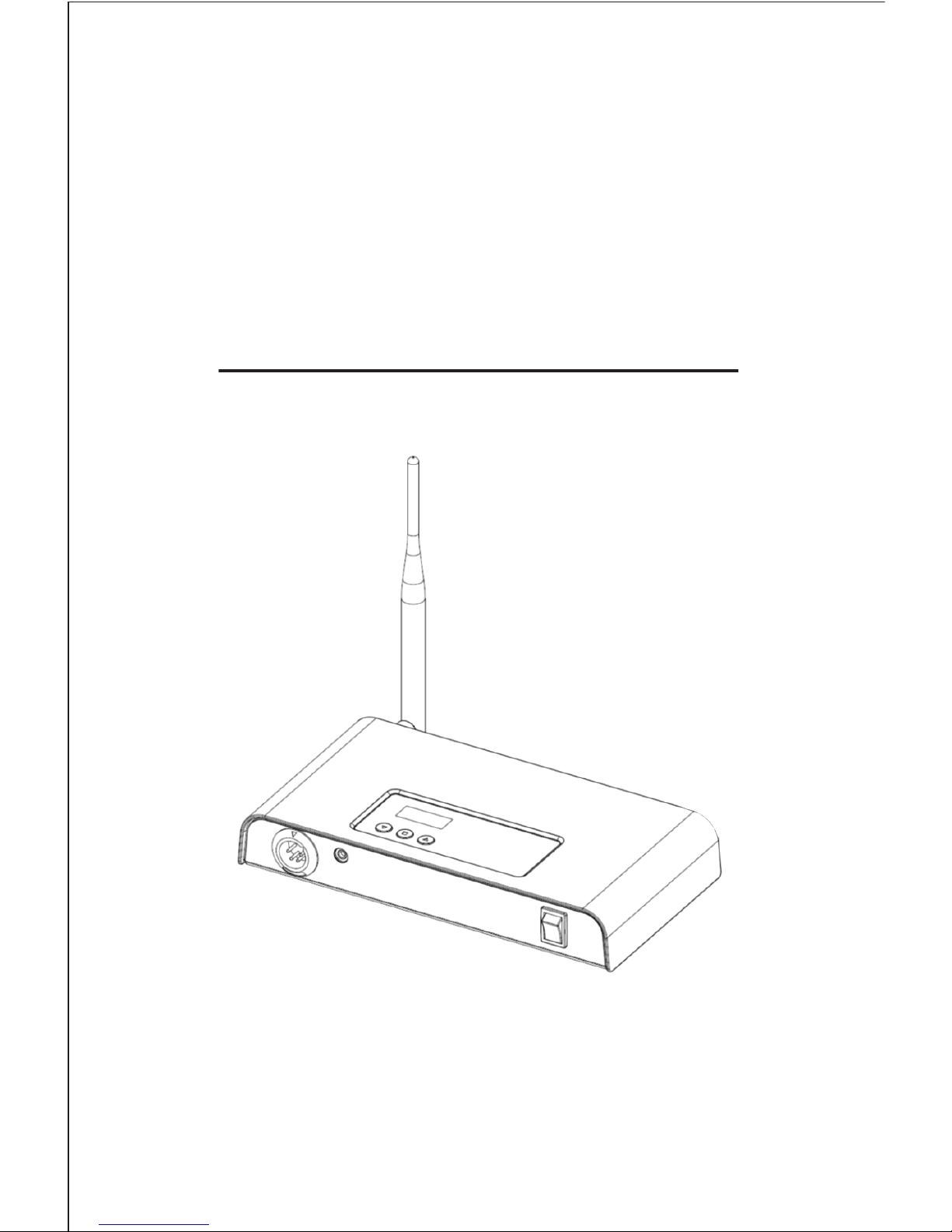
MULTICOM STATIONARY 2.4G
USER'S MANUAL
Page 2

1. General Information
1.1 Introduction
The "Multicom Stationary 2.4G" is designed by using the most advanced
Multiplex communication technology.
It serves user-friendly features and extremely convenient to operate
including a crystal clear sound quality and also long distance
communication coverage.
It gives the operation as a central broad cast station to the unlimited
number of listeners who carry the MTT-R Receiver devices with them
and also provides a communication in full duplex with up to two other
users who carry the MTT-T Multicom devices.
It is recommendable you read the user's manual thoroughly to enjoy
its maximized performance and features this station has to oer.
1.2 Main Features
* Audio publishing to the unlimited number of people who carry the
MTT-R Receiver
* Multiplex communication with up to two other users who carry the
MTT-T Multicom devices
* Long distance communication coverage over 400m typically
* Crystal clear sound quality
* 39 dierent Group selection
* Audio output HI/Low selection
* Audio volume control with 9 steps
* Side tone On/O selection
* Direct microphone sensitivity control with 5 steps
* Convenient dual external power supply source either USB plug for the
purpose of its portable using by connection Mobile phone
Power bank into it or DC 5.0V adapter via AC input
Page 3
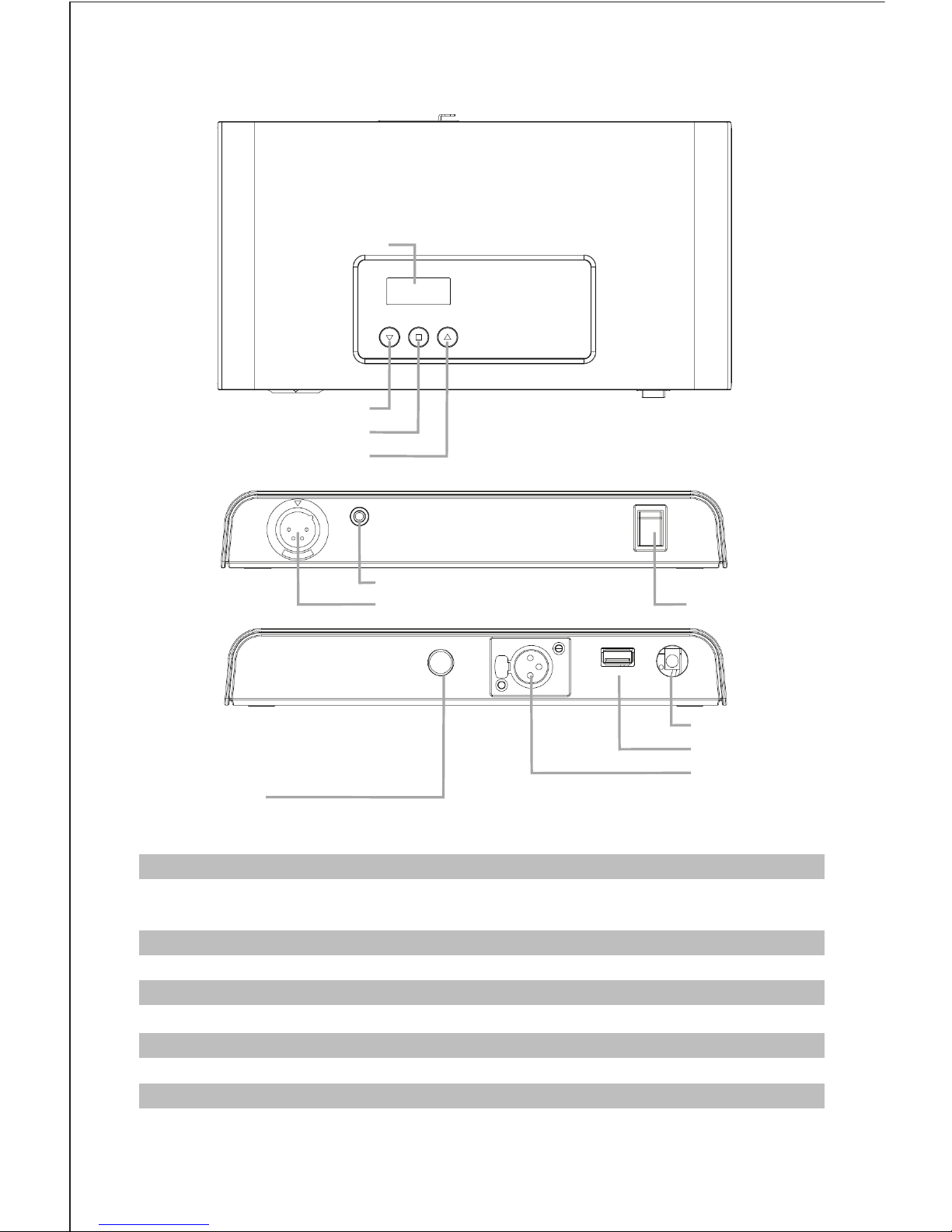
2. Controls and Indicators
Power S.W
Mode Button
Up Button
Down Button
EAR/MIC
XLR-4PINs
Antenna Jack
USB
55 JACK
XLR-3PINs
Upward : Power Turn ON / Downward : Power Turn OFF
Selection of Group Number, Device ID, Side Tone On/O, Mute Mode,
Microphone Sensitivity level and Audio Output Loud
Control to be Up the level in the selected mode
Control to be Down the level in the selected mode
3.5mm External Headset Boom Microphone Jack(EHR-01)
XLR Headset Jack
Long diversity Antenna Jack
USB Jack. compatible with Power Bank for mobile phones
55 Jack Audio Output
XLR Jack Audio Output
UP Button
Down Button
Mode Button
55 Jack
XLR-3PINs
Antenna Jack
USB
XLR-4PINs
(Desk top Mic. IN)
(Audio IN)
Power S.W
Ear / MIC
LCD
Page 4
3. How to use
3.1 Power On/O
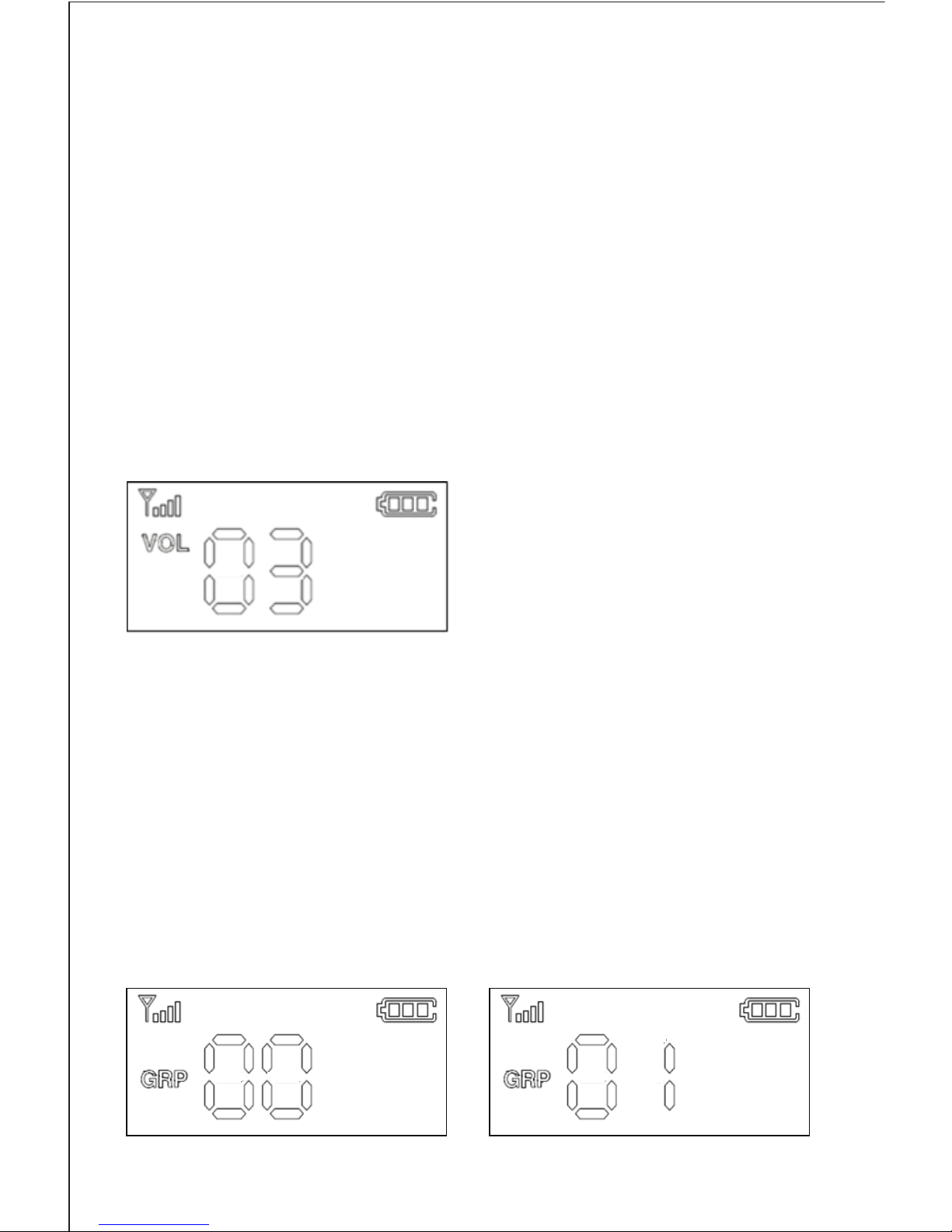
Press the "Power S.W" switch to the upward to turn the stationary power on.
The LCD display is on and shows the default volume level with "VOL 03".
If you pressed the "Power S.W" to the downward, the stationary power is
turned o.
3.2 Volume Up / Down
It gives you to adjust the hearing volume level with 9 steps as per you
prefer. Press "▲" button to control volume up and "▼" button for
volume down after turn the device power on.
It is available to adjust the volume level 0~9 from low to high.
Note; The default volume level is 3 and the volume level returns to 3
all the times whenever you power switch turned o and on.
Show the selected Group Number "00" Show the selected Group Number "01"
3.3 Group selection
Press and hold the "Mode" button longer than 3 seconds after turn the
device power on. The "GRP" symbol on the LCD is blinking.
Select the Group number 0~39 as you desire by press "▲" or "▼" button
and then release all the buttons longer than 5 seconds to x it.
Every radio needs to have a same Group number to communicate
each other in a group.
Page 5
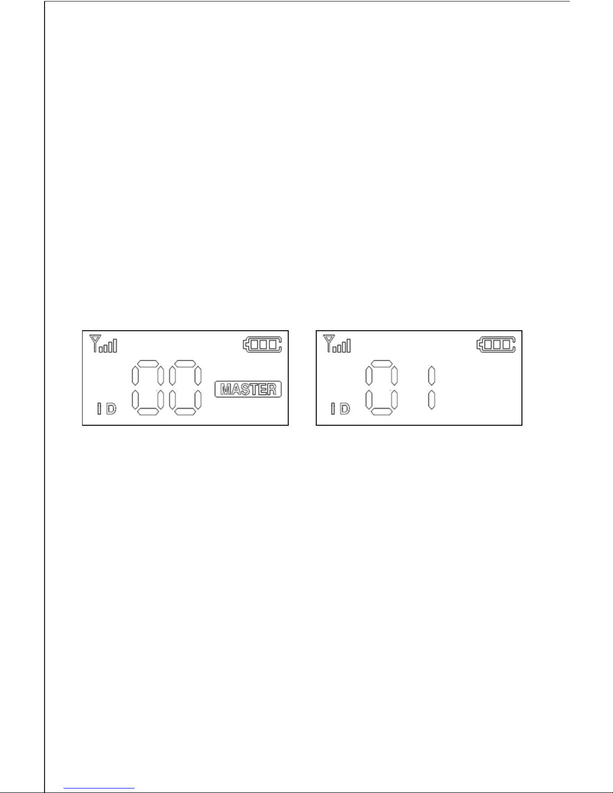
Display for the Master Display example for the Slave
3.4 ID selection
In a group, every Stationary needs to have each dierent ID per Stationary
from "00" to "99". The ID "00" becomes a master device in a group and
every group needs to have a master device with ID "00" per group without
alternative. The "MASTER" is displaying on the LCD as soon as the ID "00"
is set.
Press and hold the "Mode" button longer than 3 seconds after turn the
device power on. The "GRP" symbol on the LCD is blinking.
And press the "Mode" button one more time instantly.
The "ID" symbol on the LCD is blinking.
Select each dierent ID number per Stationary from "00" to "99" in a group
by press "▲" or "▼" button and then release all the buttons longer than
5 seconds to x it.
3.5 Audio Output mode High / Low
It serves you to choose higher audio output or lower beside of Volume
Up / Down. The higher audio output is eective when you listen to the
device at the heavy noise place. Press and hold the "Mode" button longer
than 3 seconds after turn the device power on.
The "GRP" is blinking on the LCD. Press the "Mode" button 6 times instantly.
Select either "UH" for higher audio output or "UL" for lower audio output
by press "▲" or "▼" button and then release all the buttons longer than
5 seconds to x it.
If you have any other Multicom who want to communicate with
Stationary in full duplex, you need to set the group number as the same
group number as the Stationary has and also set the dierent ID number
than the Stationary set.
For the listener who has the MTT-R, it is only required to set the same
group number as the Stationary has regardless its ID.
Page 6
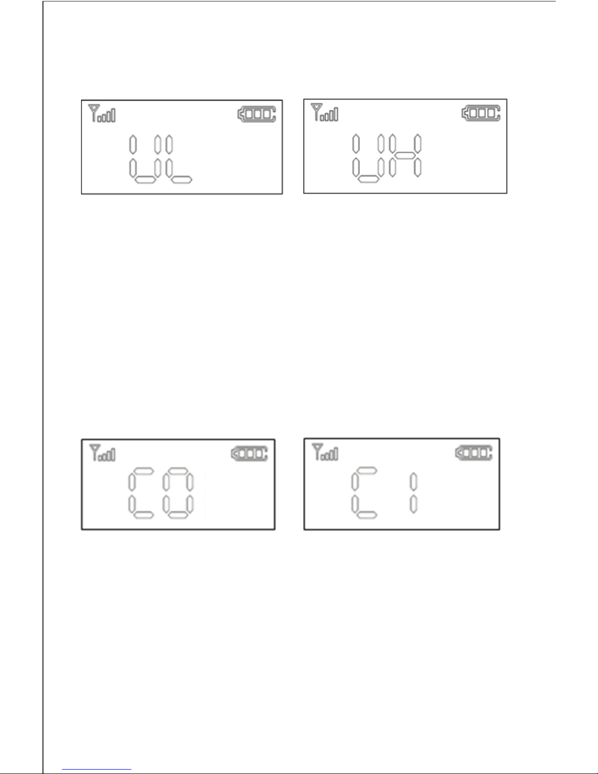
Normal Audio Output mode Loud Audio Output mode
Note;
1) The "C 1" is the lowest microphone sensitivity level and "C 5" is the highest.
2) Its default setting is "C 1".
It is available to select the microphone sensitivity up to 5 steps according
to the environment you have. Press and hold the "Mode" button longer
than 3 seconds after turn the device power on.
The "GRP" is blinking on the LCD. Press the "Mode" button 5 times instantly.
Select the microphone sensitivity level 1 ~ 5 as per you desire by press "▲"
or "▼" button and then release all the buttons longer than 5 seconds to x it.
3.7 Portable using
It is available to use the Stationary as a portable device rather than
the xed station. Please connect the Power bank for Mobile phone into
the USB port of Stationary.
After that, place the stationary wherever you prefer
Note;
1) Its default setting is "UL".
2) There might be a kind of white noise creation when you set the audio
output at "UH". Hence, it is recommendable to set the audio output at
"UL" except using the device at the heavy noise surround place.
Page 7

4. Specifications
ITEM SPECIFICATION
Radio Frequency Type ISM 2405MHz ~ 2477MHz
Type Wireless Microphone/Receiver Unit
Radio Interface ISM 2.4GHz: FSK Modulation with Frequency Hopping
Voice Codec 16bit/8KHz
Tx Max. Output Power 10dBm
RX Sensitivity -95dBm
Voice Latency <35ms
Num. of Frequency Channel 145CH
Operation Hopping 16CH
Channel Spacing 0.5MHz
Data Rate 0.5Mbps
Freq. Bandwidth 2MHz
Power Supply Output Voltage: DC 5.0V
Antenna Type Dipole Antenna (Reverse SMA type)
Antenna Gain 5.0dBi
Power Consumption Avg. 180mA
Distance Range(LOS) 200M
Frequency response 50Hz ~ 4KHz
▶ The antenna is not standard type, that is special reverse-type.
So the using antenna can’t be replace by user easily.
Page 8
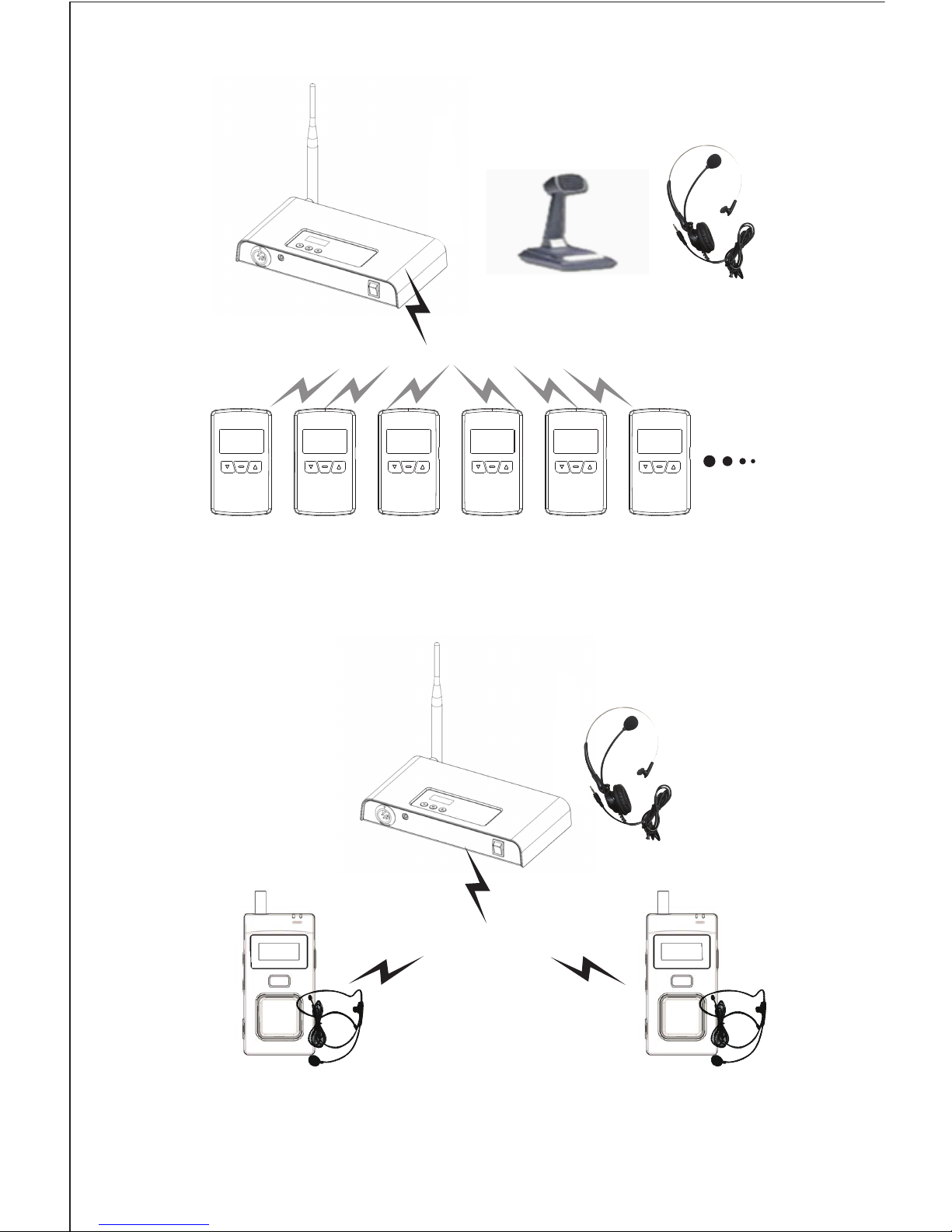
5. How to install
5.1 General Publishing
5.2 Full duplex communication with up to two other
MTT-T devices
Notice) It is required to tune the same group number only between
Stationary and MTT-R Listening device regardless its ID number.
Notice)
It is required to tune the same group number between Stationary and two
other MTT-T devices.
Also, the two other MTT-T devices should have each dierent ID per device except
the ID "00" of Stationary owned.
100~ 400m distance
Stationary
MTT-T 1
Unlimited Listeners with MTT-R
Speaking only or Speaking and Listening
100~ 400m distance
MTT-T 2
Page 9
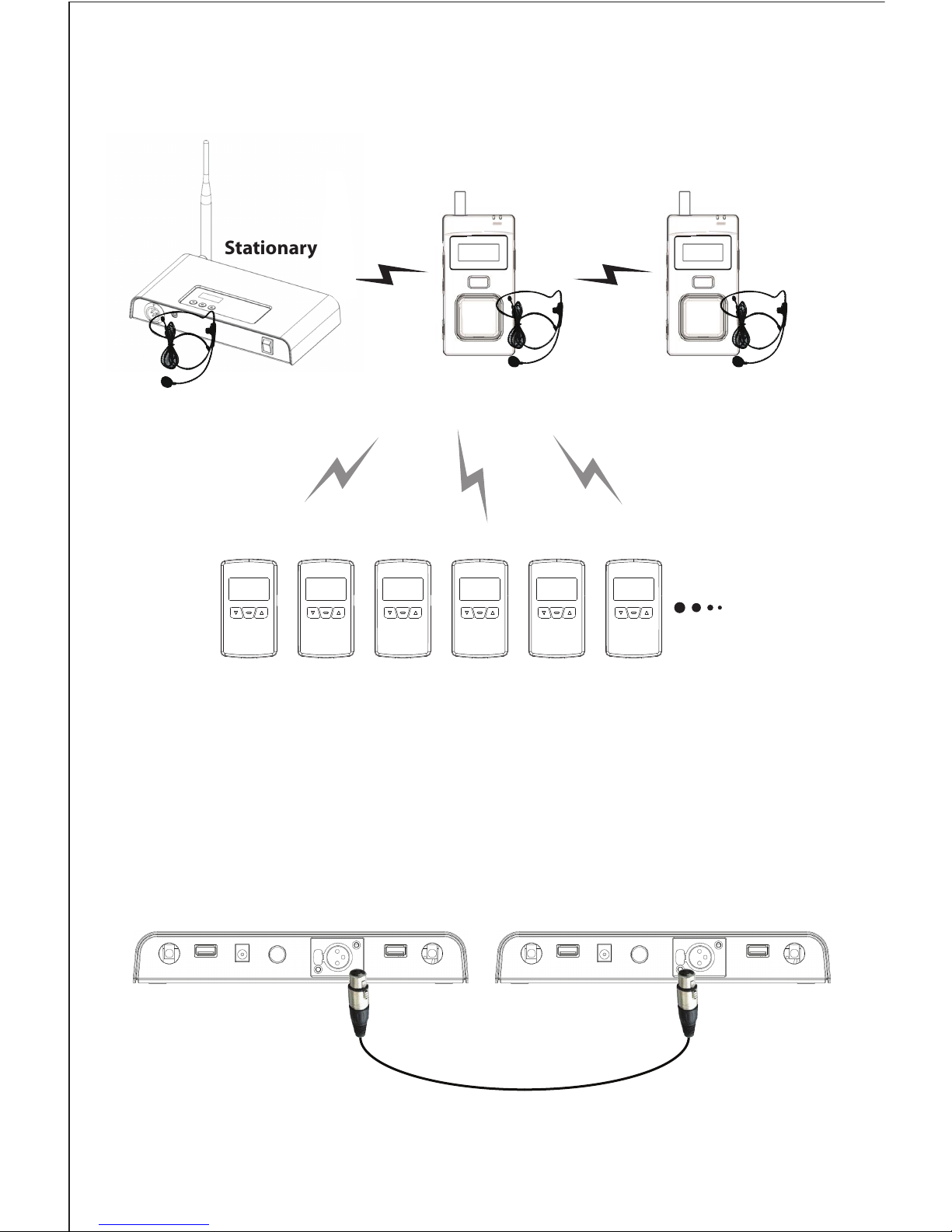
Stationary
Notice;
It is required to keep a distance longer than 10m at least between Stationary
and Stationary. Otherwise, it might cause the interference each other and
the drop of performance on both stationeries.
5.4 Line repeat communication between Stationary
and Stationary
It is available to repeat the communication in one Stationary to the other
Stationary by cable connection between two stationeries.
Please connect to two XLR 3 port of Stationeries by using "XLR Repeater
only cable".
5.3 Full duplex communication and general publishing
Unlimited number of Listeners with MTT-R
Full Duplex communications between Stationary, MTT-T1 and MTT-T2
Listening all the talking between Stationary, MTT-T1 and MTT-T2
MTT-T 1 MTT-T 2
Page 10

FCC Information to User
This equipment has been tested and found to comply with the limits for a Class B digital device,
pursuant to Part 15 of the FCC Rules. These limits are designed to provide reasonable
protection against harmful interference in a residential installation. This equipment generates,
uses and can radiate radio frequency energy and, if not installed and used in accordance with
the instructions, may cause harmful interference to radio communications. However, there is no
guarantee that interference will not occur in a particular installation. If this equipment does
cause harmful interference to radio or television reception, which can be determined by turning
the equipment off and on, the user is encouraged to try to correct the interference by one of the
following measures:
• Reorient or relocate the receiving antenna.
• Increase the separation between the equipment and receiver.
• Connect the equipment into an outlet on a circuit different from that to which the receiver is
con-nected.
• Consult the dealer or an experienced radio/TV technician for help.
Caution
Modifications not expressly approved by the party responsible for compliance could void the
user’s authority to operate the equipment.
FCC Compliance Information : This device complies with Part 15 of the FCC Rules.
Operation is subject to the following two conditions: (1) This device may not cause harmful
interference, and (2) this device must accept any interference received, including interference
that may cause undesired operation
IMPORTANT NOTE:
FCC RF Radiation Exposure Statement:
This equipment complies with FCC RF radiation exposure limits set forth for an uncontrolled
environment.
The antennas used for this transmitter must be installed to provide a separation distance of at
least 20Cm from all persons and must not be co-located or operating in conjunction with any
other antenna or transmitter .
Page 11
1) Read these instructions.
2) Keep these instructions.
3) Heed all warnings.
4) Follow all instructions.
5) Do not use this equipment near water .
6) Do not using near any heat sources such as radiators, heat resisters, stove, or other
equipment that produce heat.
European CE notice to users and product statements
This product is CE marked according to the provisions of the R&TTE
Directive(1999/5/EC). Hereby, Maytel Co., Ltd declares that this product is
in compliance with the essential requirements and other relevant
provisions of Directive 1999/5/EC.
For further information, please contact http://
www.maytel.com
Maytel Co., Ltd
#417 Doosan Venture Digm 126-1, Pyeongchon-dong, Dongan-gu, Anyang-si,
Gyeonggi-do, Republic of Korea
Tel: +82-31-478-5508
Fax: +82-31-440-9331
URL: www.maytel.com
Page 12

CONTACT INFORMATION
Manufacturer Address #417 Doosan Venture Digm 126-1, Pyeongchon-dong, Dongan-gu, Anyang-si,
Gyeonggi-do, Republic of Korea
To locate in-country MAYTEL CO., LTD., distributors of the Multicom Stationary 2.4G (MTT Stationary T-1)
please refer to the MAYTEL CO., LTD. Website http:// www.maytel.com
These distributor(s) represent local contacts for this product.
CORPORATE HEADQUARTERS:
MAYTEL CO., LTD.
#417 Doosan Venture Digm 126-1, Pyeongchon-dong, Dongan-gu, Anyang-si, Gyeonggi-do, Republic of Korea
Tel: +82-31-478-5508
Fax: +82-31-440-9331
Web: http:// www.maytel.com
This device complies with Industry Canada license-exempt RSS standard(s).
Operation is Subject to the following two condition: (1) this device may not cause interference
,and (2) this device must accept any interference, including interference that may cause undesired
operation of the device.
Page 13

EUROPEAN UNION “DECLARATION OF CONFORMITY”
DECLARATION OF CONFORMITY
MAYTEL CO., LTD.
#417 Doosan Venture Digm 126-1, Pyeongchon-dong, Dongan-gu, Anyang-si, Gyeong gi-do, Republic of Korea
declare under our sole responsibility that the product(s)
Multicom Stationary 2.4G (MTT Stationary T-1) – MS-11 2.4G
to which this declaration relate(s) is in conformance with the following standards:
EN 301 489-1 V1.9.2:2011
EN 301 489-17 V2.2.1:2012
EN 60950-1:2006/A2:2013
EN 300 328 V1.9.1:2015
following the provisions of the 1999/5/EC Directives.
 Loading...