

Page 1

Maytech Waterproof Remote Control User Manual_20191012 by Eric and Eileen
Mayte MTSKR1905WF Waterproof Remote Control
User Manual V2.0
1. Functions:
1.1 It’s the first full waterproof remote in the industry and works well in water, especially for electric
surfboards;
1.2 It’s the first wireless charging remote control in the industry;
1.3 With OLED display, easy to view throttle and battery voltage;
1.4 Standard PWM signal output, can be used in electric surfboards, electric skateboards, rc cars, rc boats,
rc airplanes, robotics, etc;
1.5 It supports motor RPM detection by motor phase wire or hall sensor wire;
1.6 It supports VESC communication protocol. Datas in VESC can be obtained and displayed through the
UART port;
1.7 It has one 30V 3A Relay mechanical switch and one 20V 2A transistor electronics switch for esk8 lights,
esurf water pump using, etc.
2. Configuration:
Remote(Transmitter):
IP rating: IP67
Triggers: Throttle trigger and Brake trigger(ESK8 mode: Throttle and Brake; Esurf mode: Throttle and Cruise
speed control, No Brake)
Sensor Type: Non-contact Hall sensor
CPU: STM8
Display: 128x64 OLED, yellow and blue screen
Battery: 3.7V/420maH
Full-charged working time: more than 2 hours
Charge interface: QI standard wireless charging interface
Transmission distance: Air 10M; Water 1M
Receiver:
Power supply: 5V OR 3.7V, automatic switch
Throttle signal output: 1-2ms 50Hz PWM 5V Max
Voltage detection range: 5-80V ±5%
Hall/Motor phase wire RPM detection range: 0-80000 ERPM
Relay switch max current: 3A
Transistor switch max current: 2A
VESC communication protocol Baudrate: 115200bps
1/17
Page 2
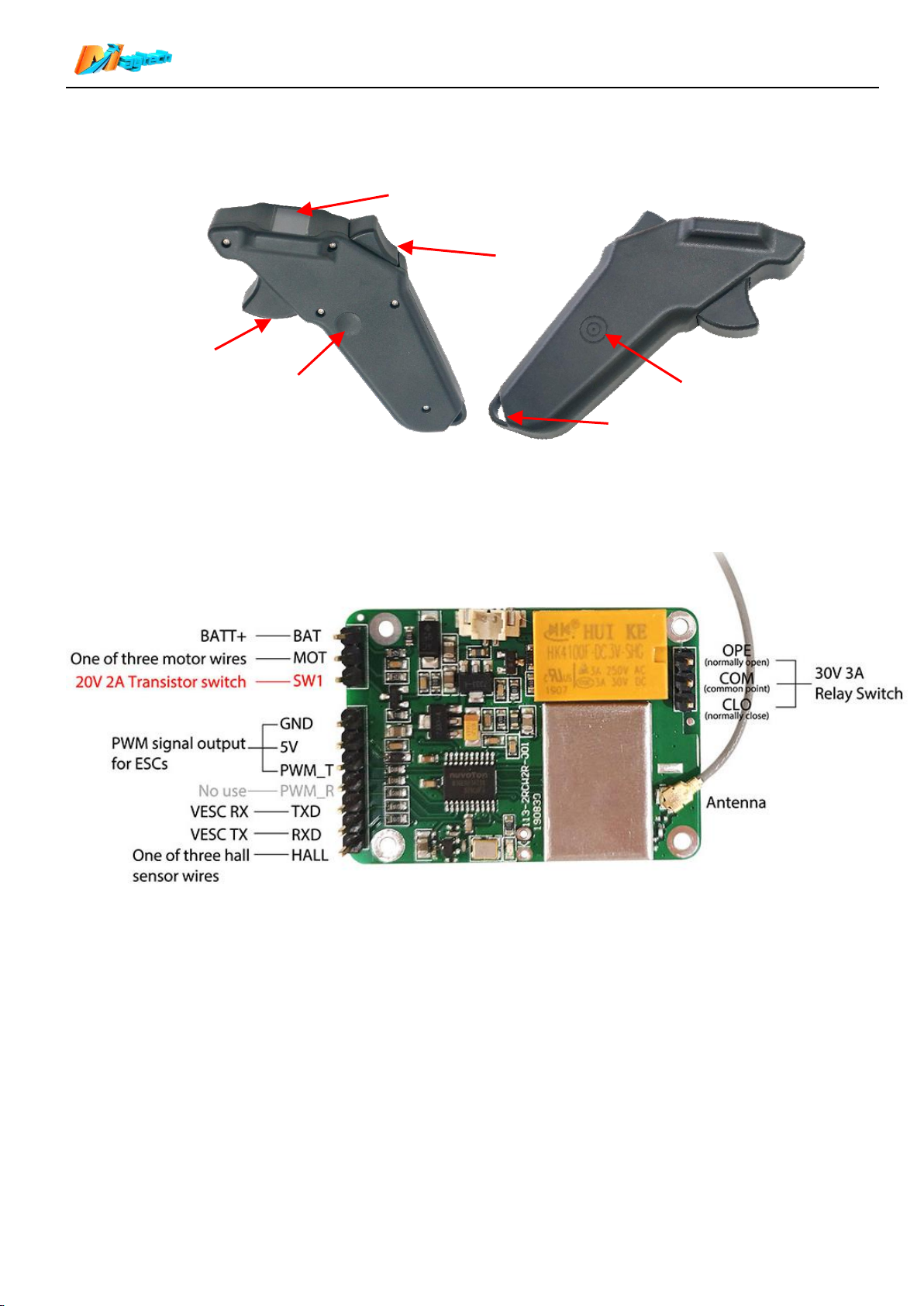
3. Remote (transmitter) appearance:
Function button
Charging point
Throttle trigger
Display screen
Brake trigger
Hole for wristband
4. Receiver appearance
Maytech Waterproof Remote Control User Manual_20191012 by Eric and Eileen
5. Receiver wiring instruction
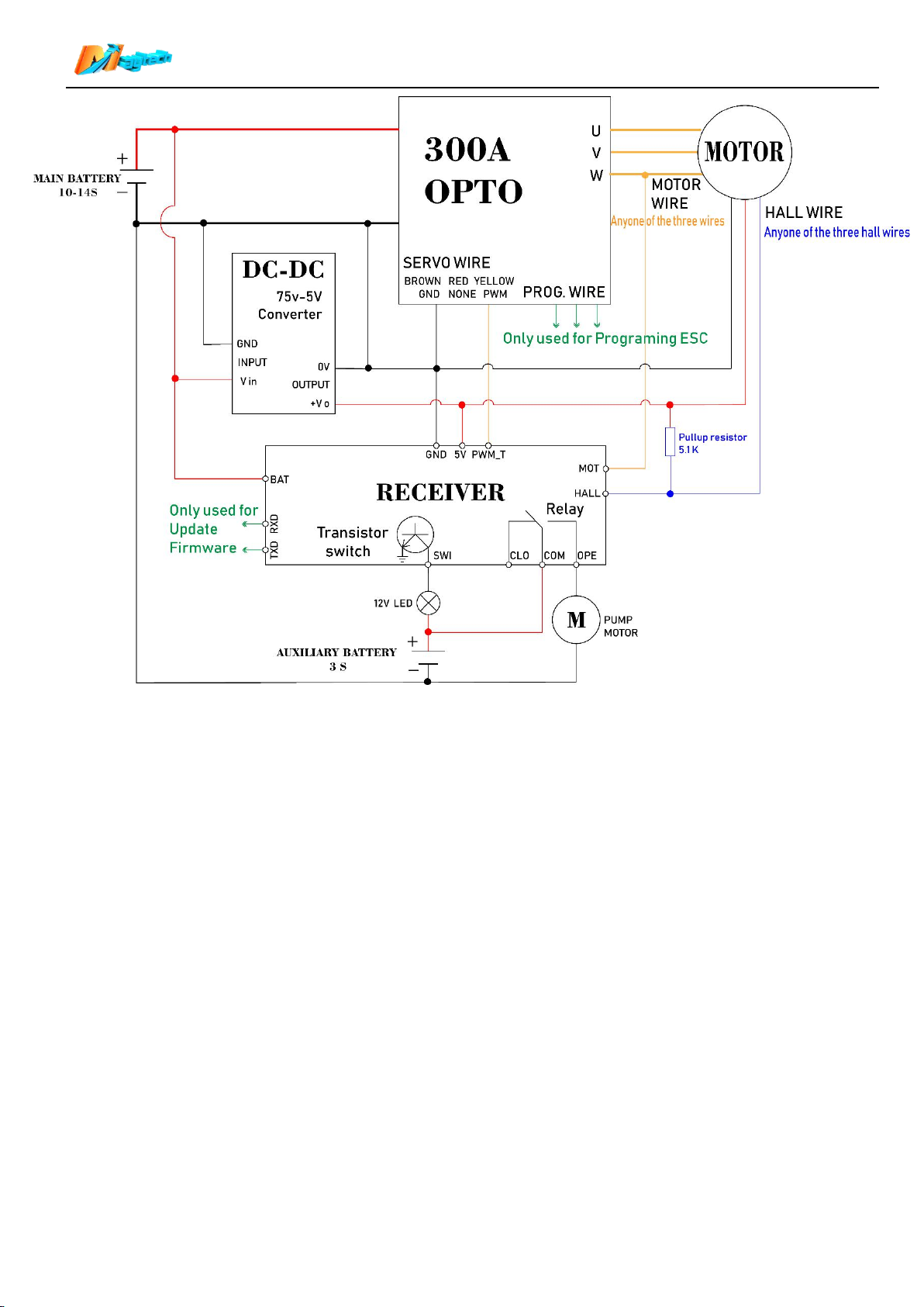
5.1 Receiver and Maytech MTSF300A-OPTO ESC wiring diagram (other ESCs can refer to
this.)
5.1.1 Note: When use hall sensor to detect motor RPM:
~If your don’t use motor hall sensor to ESC hall sensor and just use it for detecting motor RPM,
please connect one 5.1K pull-up resistor between one hall wire and +5V wire. Otherwise, hall signal
will not be detected by receiver.
~ If you use hall sensor with ESC for motor spinning, then you don’t need to connect the pull-up
resistor for motor RPM detection.
2/17
Page 3
Maytech Waterproof Remote Control User Manual_20191012 by Eric and Eileen
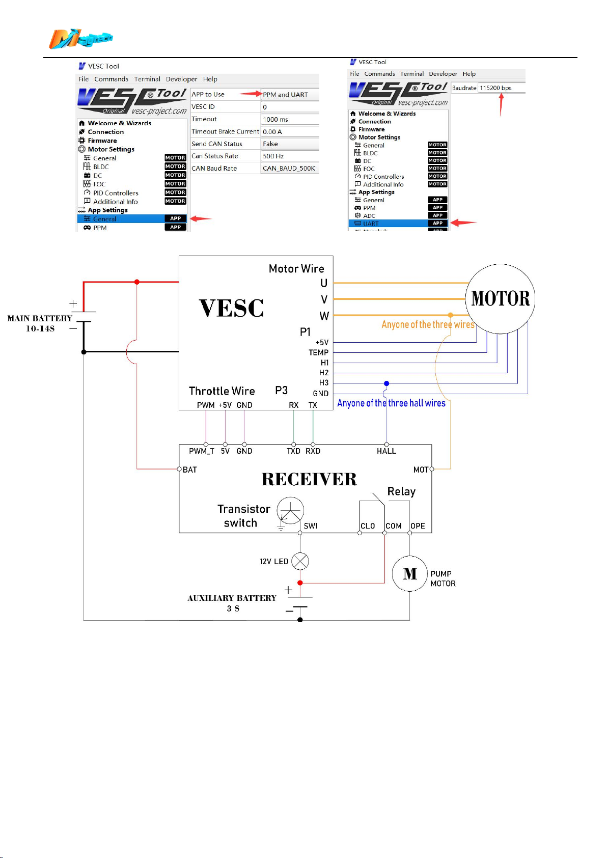
5.2 Receiver and Maytech ESCs based on Benjamin VESC wiring diagram:
5.2.1 If connect Motor hall sensor to Maytech VESC based controllers or VESCs, VESC internal pull-up
resistor will be used, so this application does not need an external pull-up resistor.
5.2.2 Cross connection of Receiver TXD/RXD and VESC RX/TX:
Receiver’s TXD>> VESC RX;
Receiver RXD>> VESC TX.
5.2.3 VESC supports UARR and PWM(PPM) throttle control. When use with Maytech waterproof remote,
you can select UART/PPM/PPM and UART three control options, and select corresponding control
in remote (“6. Speed source” and “11. VESC Thr”). We recommend to use PPM and UART control:
PPM to control throttle and UART to read voltage/current/ temperature/speed/etc. Please refer to
Item “16.2” and “16.5”in this manual.
5.2.4 Please set “Baudrate” to “115200 bps” in VESC_TOOL.
3/17
Page 4
Maytech Waterproof Remote Control User Manual_20191012 by Eric and Eileen
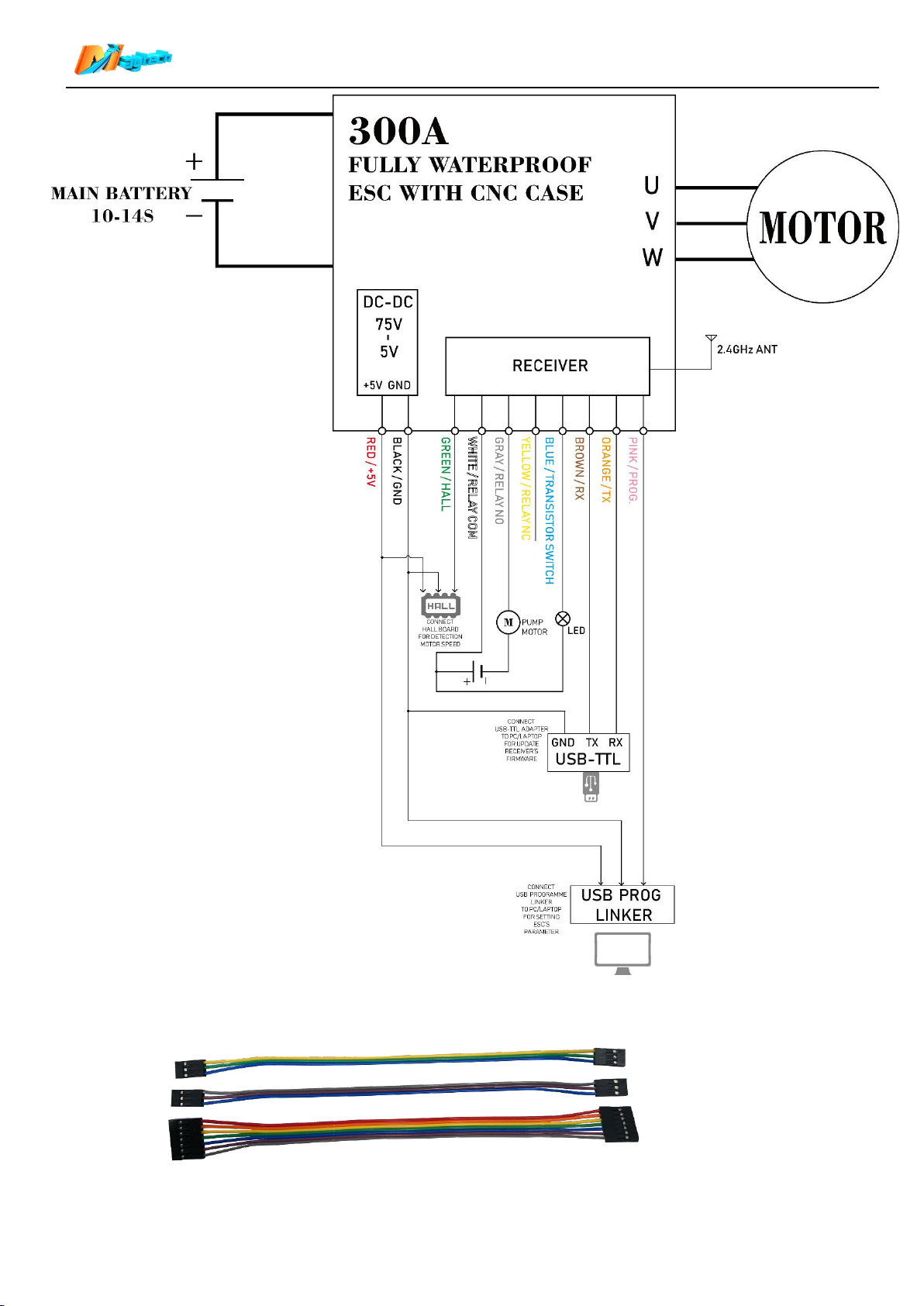
5.3 Maytech MTSF300A-OPTO-WP fully waterproof ESC with built-in UBEC and Receiver
wiring
:
5.3.1 To achieve the simplest external wiring, this ESC has integrated the voltage sampling of the main
battery, motor phase wire RPM measurement, hall sensor RPM measurement with pull-up resistor,
and DC-DC module(UBEC). You only need to connect the ESC 10 signal wires accordingly.
5.3.2 The 10 signal wires derived from the ESC have the functions of upgrading the firmware of the
receiver, adjusting ESC parameters, two switches, hall RPM detction, etc. If you don't need these
functions, these wires can be disconnected. But please keep the wires ends dry.
4/17
Page 5
Maytech Waterproof Remote Control User Manual_20191012 by Eric and Eileen
5.4 Receiver accessories
5.4.1 DuPont Cables:One 7pin 20cm;two 3pin 20cm. (color may be different for different batch.)
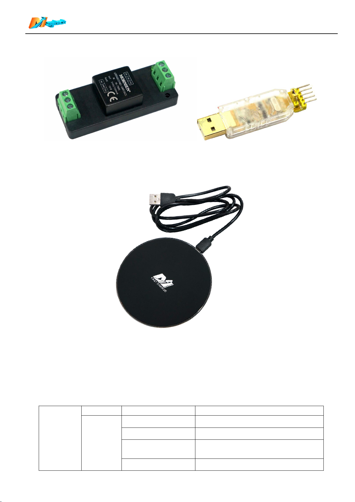
5.4.2 DC-DC module (BEC/UBEC), Input: DC 18-75V Output: DC 5V, 1200ma. It can convert main battery
voltage to 5V output for receiver. If your ESC doesn’t have built-in 5V power supply, you will need
this module for receiver (this module needs to be purchased separately).
5/17
Page 6
Maytech Waterproof Remote Control User Manual_20191012 by Eric and Eileen
Function
Button
Operation
Current display
Next display after the operation
Long press
OFF
Long press 3S to switch on the remote
Main interface
Long press 3S to switch off the remote
Main menu or
Sub-menu
Enter the sub-menu/ Data Setting Interface
Pairing interface
Quit Pairing process
5.4.3 USB-TTL module is used to update receiver firmware. If you need this module, please purchase it
separately.
6. Wireless charger
To ensure the waterproof effect, the remote(transmitter) only supports wireless chargers which meet QI
standard. The charger in the kit is shown in the figure below. Charging time is no more than one hour.
7. Switch on/off:
【 Switch on 】 When remote is off, long press the function button 1s, screen displays Maytech logo and
firmware version to switch on the remote.
【Switch off】When remote is on, long press the function button 1.5s, screen displays POWER OFF to switch
off the remote.
8. Function button operating instructions:
6/17
Page 7
Maytech Waterproof Remote Control User Manual_20191012 by Eric and Eileen
Calibration interface
Quit Calibration process
Wheel diameter/Gear
ratio date setting
interface
Select One hundred / Ten / One / Decimal
place
Short press
one time
Main interface
Switch data display on main interface
Main menu and
sub-menu
Switch options in the menu
Data input interface
Data plus one
Short press
two time
Main interface
Relay switch suction and release
Short press
three time
Main interface
Transistor switch ON and OFF
Operation
The other trigger
position
Current display
Throttle output
Press throttle
trigger
Brake trigger at
original position
Main interface
Output corresponding throttle signal
Press brake
trigger
Throttle trigger at
original position
Main interface
No throttle signal output
Throttle trigger not
at original position
Main interface of
ESK8 mode
Receiver outputs brake signal. The braking
force is determined by the position of the
brake trigger.
Throttle trigger
at 10%-100%
throttle position
Main interface of
ESURF mode
After 3 seconds, it enters the cruise speed
control mode, and the throttle keeps its
original output after release. The cruise
control will be cancelled when the brake
trigger is pressed again to the end or the
throttle trigger exceeds the cruise throttle
value.
Mode
Speed
Conversion formula
Esk8
Skateboard speed (KM/H)
ERPM/Motor Poles/Gear Ratio*60*3.14*Wheel Dia/1000000
Skateboard speed (MPH)
ERPM/Motor Poles/Gear Ratio*60*3.14*Wheel
Dia/1000000*0.6214
Esurf
Esurfboard propeller RPM (RPM)
ERPM/Motor Poles/Gear Ratio
9. Trottle and brake triggers operating instructions:
10. Speed source:
Speed sginal is detected by motor phase wire or hall sensor wire or VESC. Please select 【Speed Source】
in remote manual Item6 and make sure hardware is connected correct and well. The original acquisition
speed signal is the electrical speed of the motor (ERPM). Then remote will convert it to RPM or Speed and
display.
11. Distance:
11.1 This function only works in Esk8 mode for electric skateboard.
7/17
Page 8

Maytech Waterproof Remote Control User Manual_20191012 by Eric and Eileen
11.2 When【Speed Source】is set to【Motor Wire】or【Hall Sensor】, the distance is the accumulation of the
product of speed and time per 0.1 second.
11.3 When【Speed Source】is set to【VESC】, remote and receiver will read VESC’s ABS data by UART port
and calculate it to distance and display.
12. Main battery voltage display:
12.1 This function works in both Esk8 and Esurf modes.
12.2 When【Speed Source】is set to【VESC】, it will obtain VESC voltage information by UART port;
Otherwise, voltage information is obtained by BAT port on receiver PCB.
12.3 Please make sure receiver GND and your main battery GND are connected(common ground).
12.4 If receiver is not connected to main battery or VESC UART port, remote will not display anything about
main battery.
12.5 If receiver gets voltage information, remote will show voltage in bars according to preset 【 Batt. Type】
and 【Batt. Ser Num】.
Under the voltage bar on remote screen, it’s marked 【xx Batt.】. “xx” means current 【Batt. Ser Num】value,
please check if it’s same as your battery specification.
If 【 Batt. Type】or 【Batt. Ser Num】is set different from your battery’s actual value, voltage display will be
incorrect. Please make sure correct settings of both.
If voltage bars only have 2 or less left, the bars and 【xx Batt. 】words on screen will flash to remind you
charge your battery.
13. Voltage, Current, Temperature display:
13.1 When【Speed Source】is set to【VESC】, Remote and receiver will obtain voltage/current/temperature
information by VESC UART port. The function automatically takes effect after correct connection and settings
with VESC. You can press the Function Button to turn over the main interface data to view these data. Please
refer to “Item 5.2” in this manual.
13.2 It works for both Esk8 and Esurf modes when use with VESC.
13.3 VESC has temperature sensitive resistor on PCB. It can measure VESC’s temperature. But motor
temperature display needs:
13.3.1 Motor has built-in 10K NTC thermistor and it’s connected to the Temperature pin of hall sensor
connector.
13.3.2 In VESC_TOO, Beta Value for Motor Thermistor is set to 3950K.
14. Relay and Transistor switches using instructions:
14.1 Both switches work in Esk8 and Esurf modes.
14.2 When relay switch is in original position(no display of【1】in Screen Main interface) , COM(common point)
and CLO(normally close) are connected.
14.3 When relay switch is moved (display of 【 1 】 in Screen Main interface) , COM(common point) and
OPE(normally open) are connected.
14.4 Max current of relay switch contacts is 3A. Recommend use this switch for water pump or main lighting
system.
14.5 When Transistor switch is turned on, the load circuit will be connected to the GND terminal. Max current
2A. Recommend to use it for indicator LED.
14.6 When transistor switch is on (display of【2】 in Screen Main interface), transistor switch source will be
connected to GND and turn on LED. When it’s off(no display of【2】in Screen Main interface), LED is off.
14.7 Recommend 5-12V voltage for the transistor switch. Voltage over 20V will burn the transistor.
14.8 Transistor switch pin SWI is closed to BAT pin and MOT pin. Please make sure no electrical contact
between them. Or it will burn transistor.
8/17
Page 9
Maytech Waterproof Remote Control User Manual_20191012 by Eric and Eileen
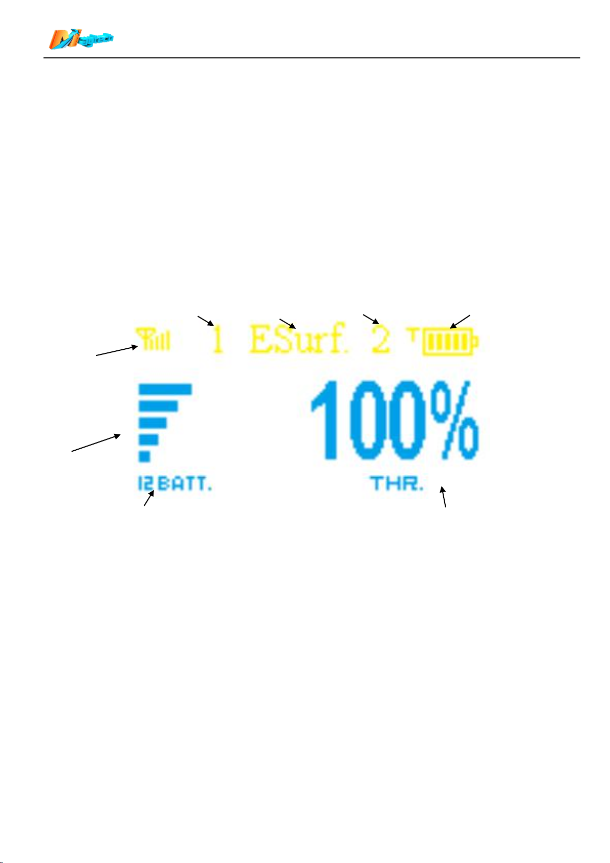
Signal strength
Remote BATT voltage
Main battery voltage
Control mode
Main BATT. Num
Throttle signal percentage
Relay switch
Transistor switch
14.9 When controlling the LED by relay switch and transistor switch, you should consider whether there is a
current limiting resistance inside the LED. If it is not, please connect one current limiting resistance outside,
or it will burn the LED.
15. VESC throttle control type
15.1 When use VESC and UART for throttle output, VESC will automatically identity your remote throttle
settings. It has two modes:
15.2 【Current Mode】take motor current as control target. When release the trigger, it will free slide and has
no danger. For normally electric skateboards and surfboards, recommend this mode.
15.3 【Duty Cycle】take motor RPM as control target and motor RPM will increase as throttle increase and
decrease with throttle decrease. When release the trigger and it will instantly brake down to zero and throw
people off because of inertia. This mode is only suitable for differential control similar to tank operation.
16. Display:
16.1 Throttle percentage (Main interface after remote switch-on):
16.1.1 【 Signal strength 】 Signal strength between remote and receiver. Recommend that the direct
distance between them is no more than 10 meters in air and no more than 1 meter in water.
16.1.2【Remote BATT voltage】The voltage percentage of the remote built-in lithium battery.
【BATT. Num】Main Batt. Series Number.
16.1.3 【Main battery voltage 】The voltage is measured by receiver or obtained by VESC. The receiver
reports the main battery voltage to the remote, which displays the power ratio of the main battery
according to the preset number of battery. If your main battery electricity is used up, the bars and
【xx Batt.】words on screen will flash to remind you charge your battery.
Attention:
When speed source is not set to VESC, If receiver is not connected to main battery, remote will not
display anything about main battery;
When speed source is set to VESC, it will obtain VESC voltage information automatically.
16.1.4 【Control mode】ESK8-Electric skateboard mode,ESurf-Electric surfboard mode.
ESK8: Neutral position, PWM output 1500 microsecond;
Press throttle trigger, PWM output range 1500-2000 microsecond;
Press brake trigger, PWM output range 1500-1000 microsecond;
9/17
Page 10
Maytech Waterproof Remote Control User Manual_20191012 by Eric and Eileen
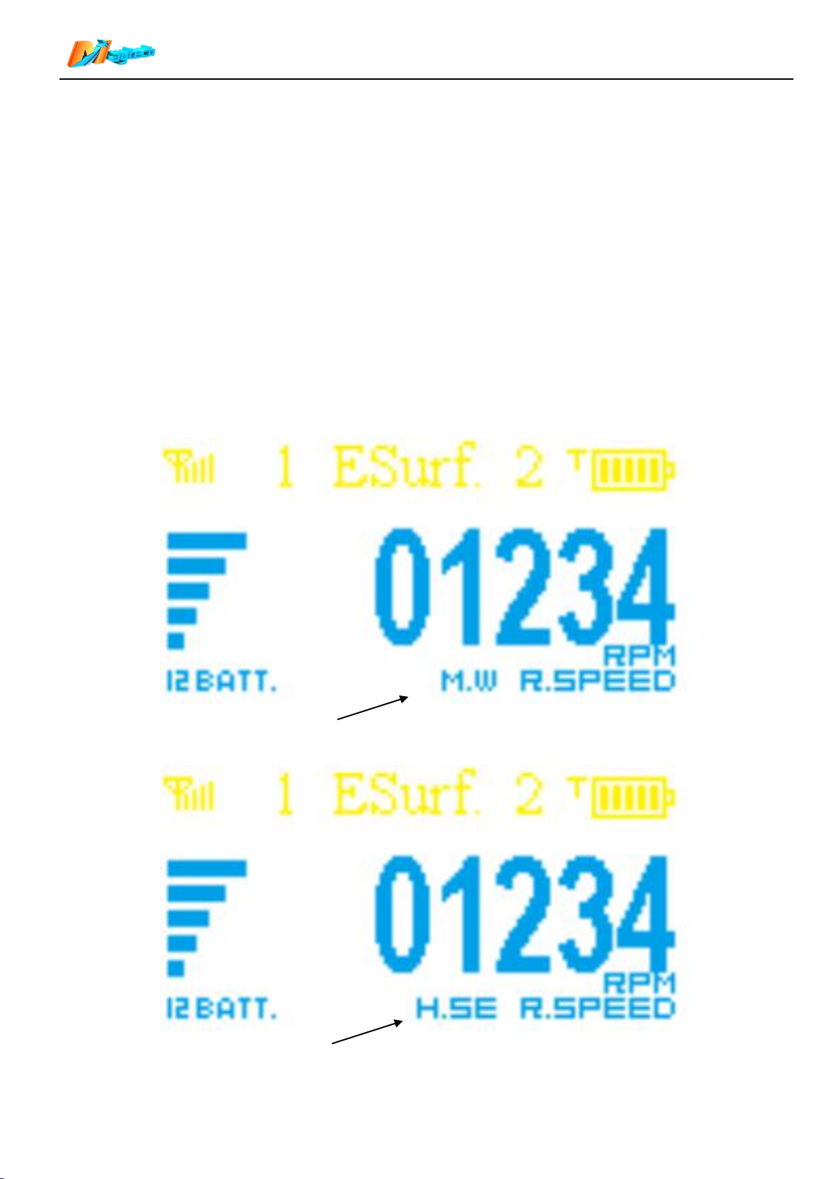
Motor RPM is detected by one Motor phase wire.
Motor RPM is detected by one hall sensor wire.
Press two triggers together, the brake trigger gets priority output.
ESurf: Neutral position, PWM output 1000 microsecond;
Press throttle trigger, PWM output range 1000-2000 microsecond;
When Throttle trigger is at 10%-100% throttle position, long press brake trigger enter cruise
speed control mode(please refer to “Item 9” in this manual) .
16.1.5 【Throttle signal percentage】Value of the current output PWM signal percentage. In ESK8 mode,
display range is ±100%; in ESurf mode, display range is 0-100%.
When VESC Thr is set to None, receiver’s PWM_T output PWM signal as throttle signal.
When VESC Thr is set to Current/Duty Cycle, receiver’s TXD/RXD output signal to VESC RX/TX as
throttle signal .
16.1.6 【Relay switch】Refer to “Item 8” in this manual.
16.1.7 【Transistor switch】Refer to “Item 8” in this manual.
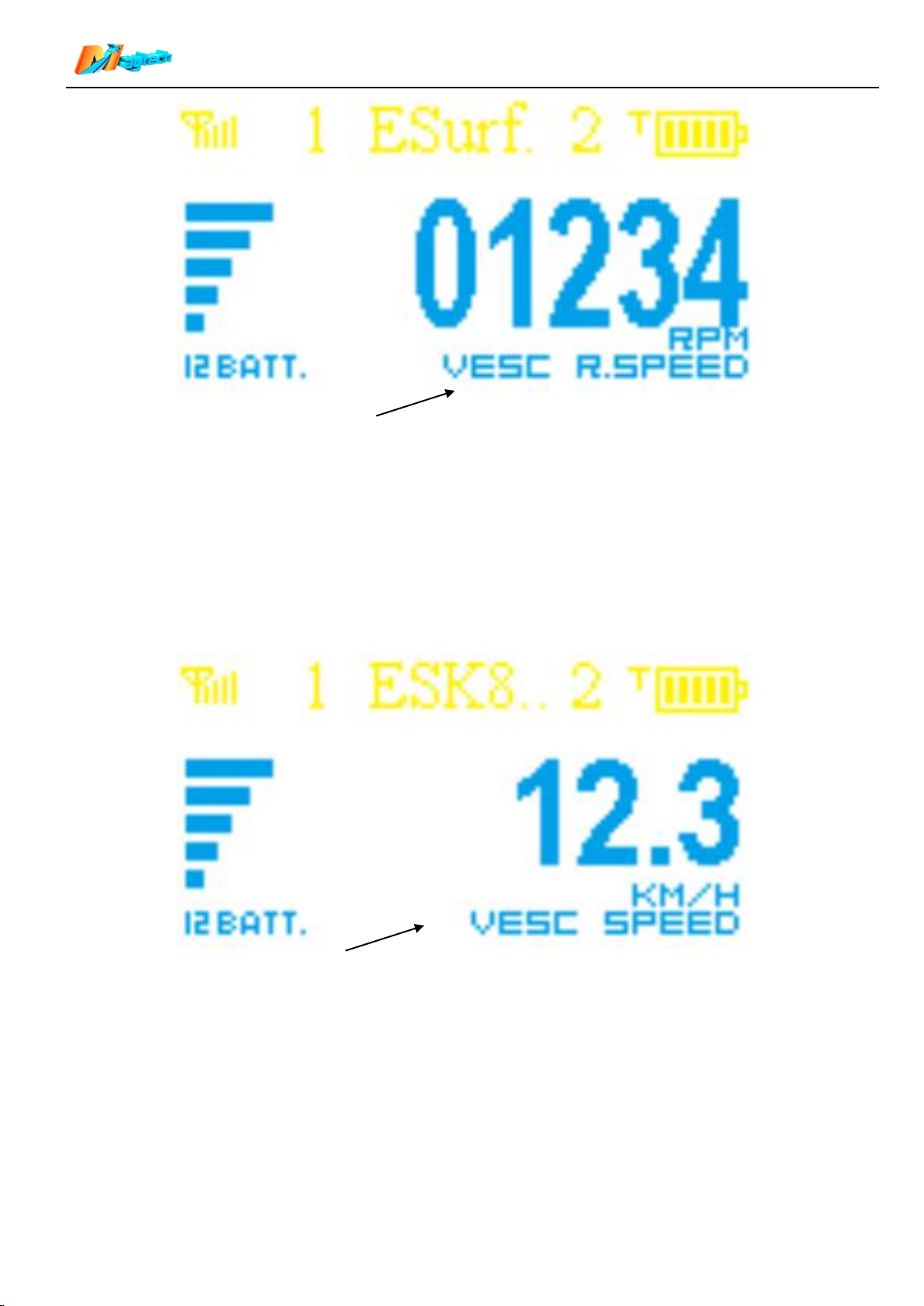
16.2 Esurf mode Motor RPM display:
In Esurf mode, after selecting suitable Speed Source, when screen displays main interface, short press
Function Button, it will change to Motor RPM interface. For different Speed Source, text in the lower right
corner is different.
10/17
Page 11
Maytech Waterproof Remote Control User Manual_20191012 by Eric and Eileen
Motor RPM is obtained by VESC.
Speed is obtained by VESC and showed in KM/H.
16.3 Esk8 mode Speed and Distance display:
16.3.1 In Esurf mode, it only has the motor RPM interface of real time RPM of propeller. It can’t display
speed and distance.
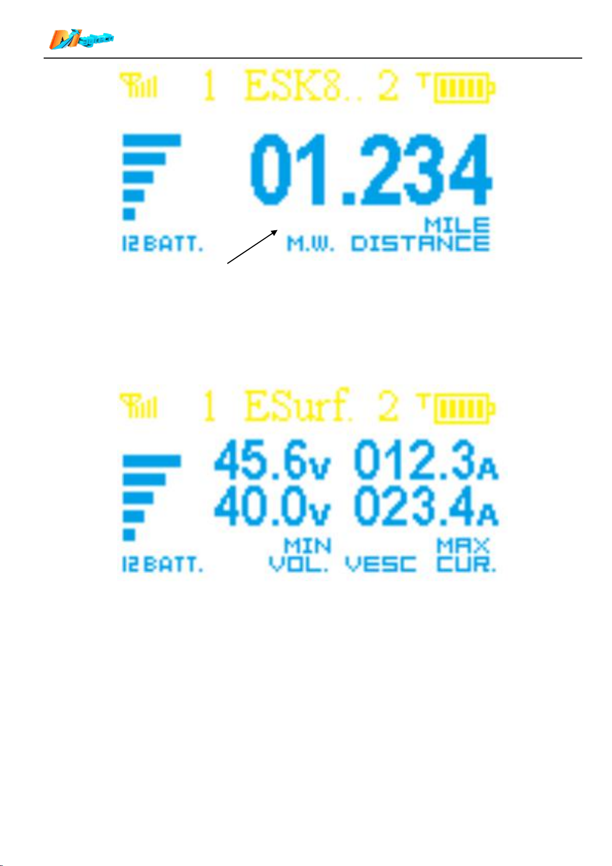
16.3.2 In Esk8 mode, after selecting suitable Speed Source, when screen displays main interface, short
press Function Button, it will change to Speed interface, press again, it will change to Distance
interface.
16.3.3 You can set the unit Km&KM/H or Mile&MPH for Speed&Distance.
16.3.4 For different Speed Source, text in the lower right corner is different.
11/17
Page 12
Maytech Waterproof Remote Control User Manual_20191012 by Eric and Eileen
Distance is calculated based on RPM detected by one motor phase wire and
showed in Mile.
16.4 Voltage and Current display:
For both Esurf and Esk8 modes, the interface must be displayed after selecting【VESC】in【Speed Source】.
Data is obtained from the VESC via the UART port. The voltage shows the current value and the minimum
value after running. The current shows the current value and the maximum value after running.
16.5 VESC temperature and motor temperature display
For both Esurf and Esk8 modes, the interface must be displayed after selecting【VESC】in【Speed Source】.
Data is obtained from the VESC via the UART port. It shows the current value and the minimum value after
running.
12/17
Page 13
Maytech Waterproof Remote Control User Manual_20191012 by Eric and Eileen
1
Thr. Mode
Control mode
【Select options in Main
Menu】
Short press function button,
jump to the next option;
Long press function button,
select current option
and enter sub-menu.
2
Batt. Type
Main battery type
3
Batt. Ser Num
Main battery Series Number
4
Pair
Pair remote and receiver
5
Calibration
Remote throttle calibration
6
Speed Source
Speed source
7
Motor Poles
Motor pole pairs
8
Wheel Dia.
Wheel diameter
9
Gear Ratio
=Wheel pulley/motor pulley
10
Dist. Unit
Distance and Speed unit
11
VESC Thr.
VESC throttle control type
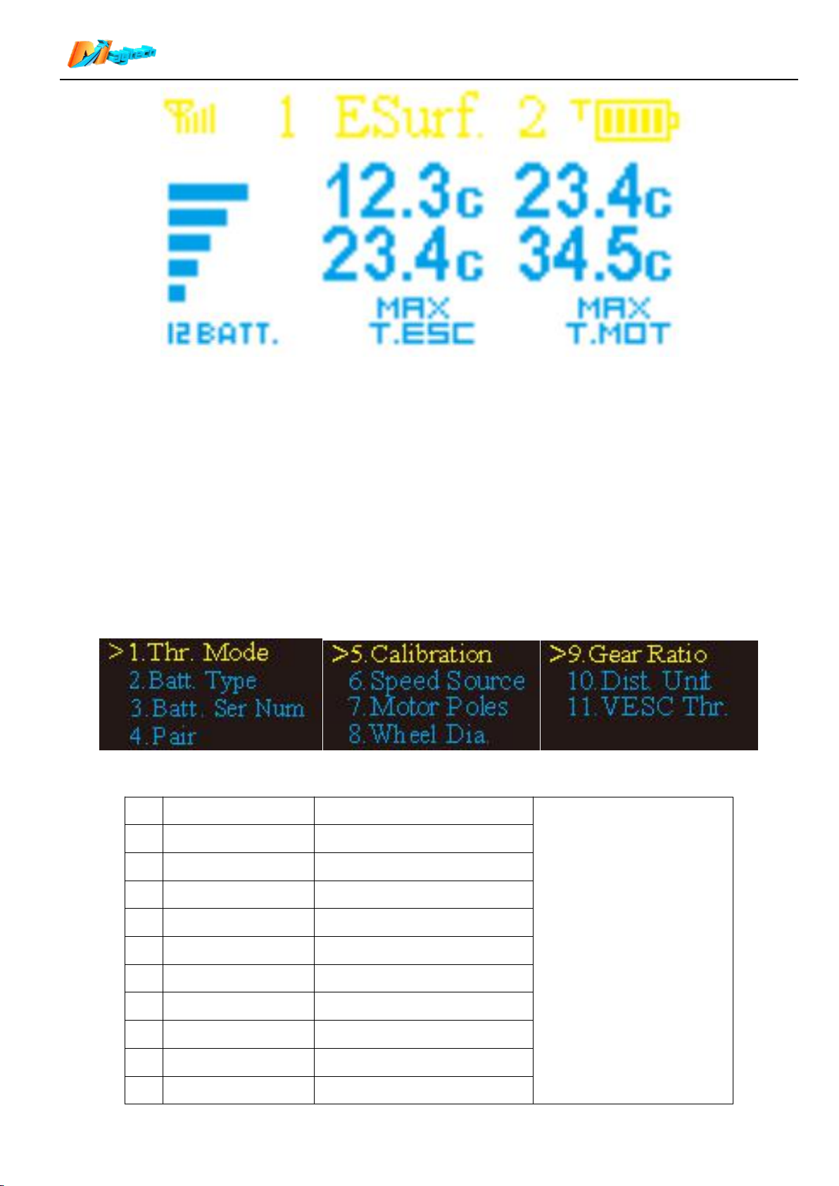
17. Entry and Exit Main Menu
【Entry Main Menu】Hold brake trigger to the end and press Function button.
【Exit Main Menu】When the parameters are edited, press the brake to the end, exit from the sub-menu to
the main menu, and then press again to exit from the main menu to the main interface. Special case: when
set “Calibration”, trigger will be occupied, please long press function button to exit from Calibration sub-menu
to main menu.
18. Main Menu Description
Main Menu has 11 options, with specific parameters in the sub-menu under each option:
13/17
Page 14
Maytech Waterproof Remote Control User Manual_20191012 by Eric and Eileen
19. Sub-Menu Description
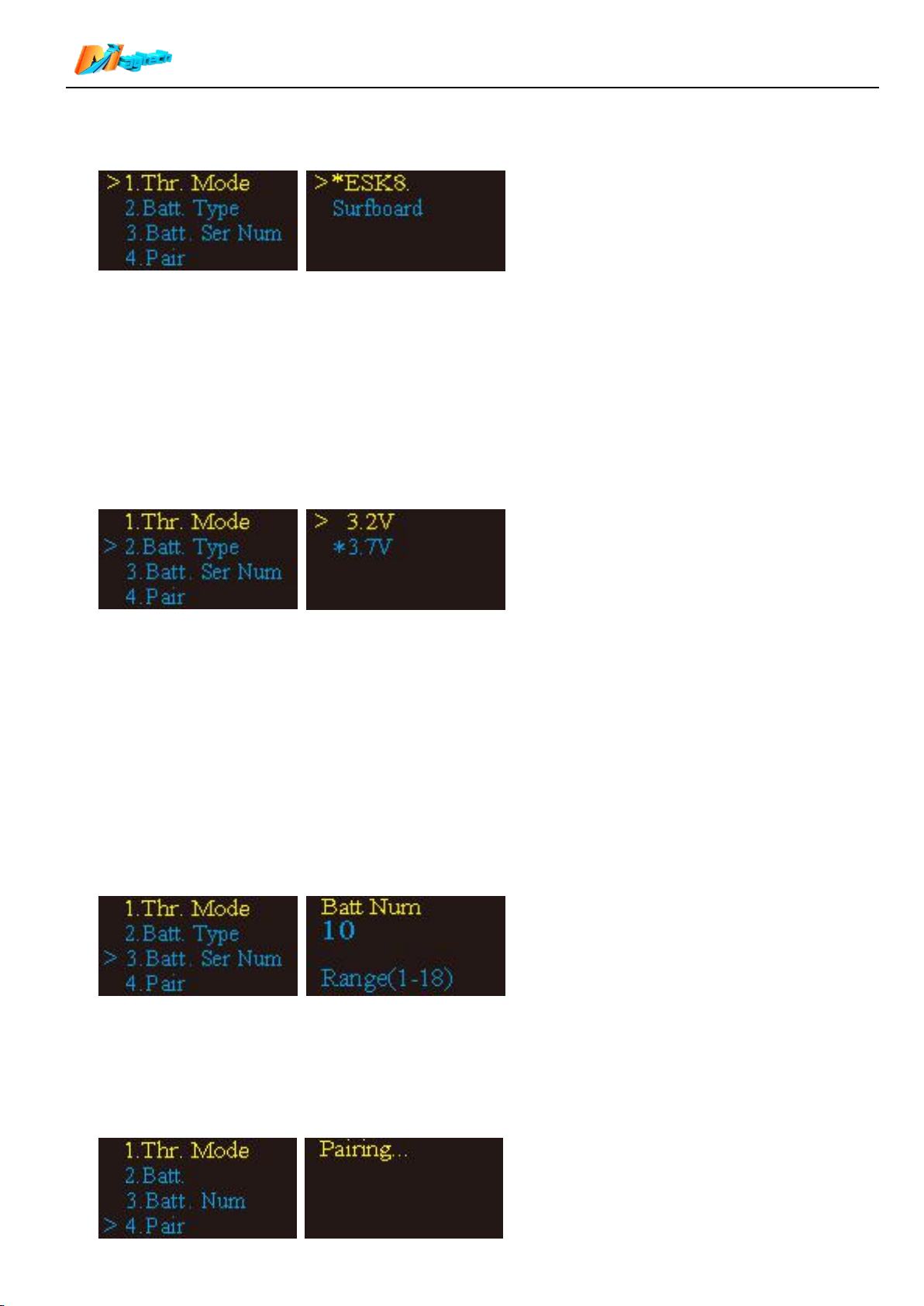
19.1 Thr. Mode
Select 【>1.Thr. Mode】and long press function button for 1 second to enter Sub-menu.
【ESK8.】Electric skateboard mode
【Surfboard】Electric surfboard mode
Please refer to “Item 16. Display” to check the two modes details:
Short press function button to select control mode. Mode with * is current mode, Mode with >is selected
mode. Long press function button to move * to the mode you wanted. After setting, press brake trigger back to
main menu.
Default: Surfboard.
19.2 Batt. Type
Select 【>2.Batt.】and long press function button for 1 second to enter Sub-menu.
【3.2V】Lithium-ion ferrous phosphate batteries; 3.2 V per cell.
【3.7V】Lithium ion or lithium polymer batteries; 3.7 V per cell.
The full voltage of the main battery can be obtained by matching this parameter with “3. Batt. Num”.
According to the collected actual voltage , it will calculate the percentage of power, display it on the top of the
home screen.
Short press function button to select control mode. Mode with * is current mode, Mode with >is selected mode.
Long press function button to move * to the mode you wanted. After setting, press brake trigger back to main
menu.
Default: 3.7 V
19.3 Batt. Ser Num
Select 【>3.Bat.Num】and long press function button for 1 second to enter Sub-menu.
Press function button to add Battery number. Max number is 18.
Press brake trigger to save number and return to main menu.
Default: 10
19.4 Pair
14/17
Page 15
Maytech Waterproof Remote Control User Manual_20191012 by Eric and Eileen
1. If remote and receiver are paired successfully before, then no need to pair them again.
2. If remote and receiver does not get paired before, please pair them according to below steps:
1) Turn off receiver.
2) Select 【 >4.Pair】 and long press function button for 1 second to enter pair status. When screen shows
【Paring…】, turn on receiver and it will auto-pair with remote control in 0.5 second. Red led lights steady.
Pairing competed. Remote screen will automatically return to main menu.
If auto-pairing time is over 1 second and screen still shows【Pairing…】, pairing fails and it needs to turn off
and turn on receiver again to pair them. If you don’t want to continue the pairing process, long press function
button to exit to main menu.
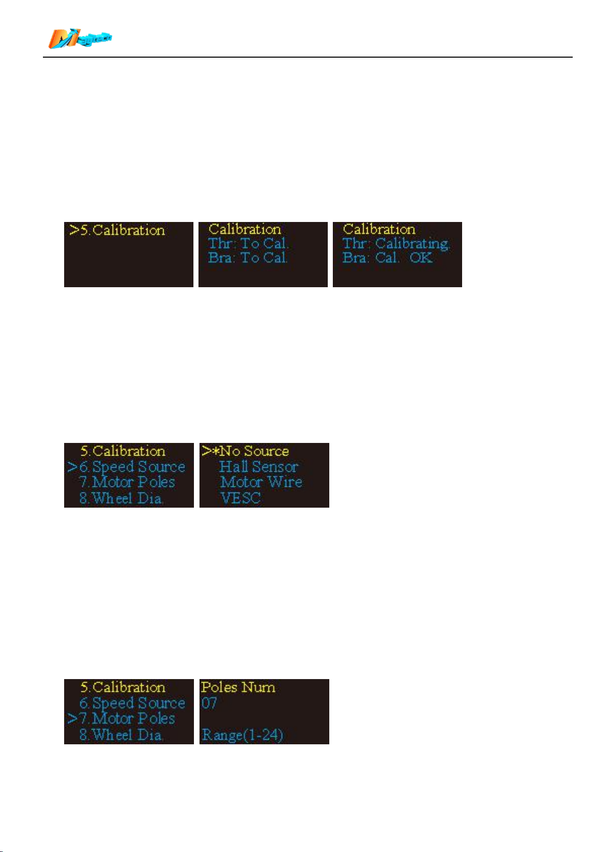
19.5 Calibration
Due to environmental changes during use, remote calibration may be out of proportion to the output of PWM
signal. Then it needs to do calibration.
Select 【 >5.Calibration 】 and long press function button for 1 second to enter Sub-menu. Once enter
calibration, it must need to be finished. If don’t continue calibration and exit, remote and receiver will stop
working together.
Press throttle trigger to top and loose it. Then press brake trigger to top and loose. When press trigger, the
screen will prompt【Calibrating】 and 【 Cal. OK】.
After both two are【 Cal. OK】, long press function button to return to main menu and save the results.
19.6 Speed Source
This is an important parameter. If you want to show RPM or Speed&Distance in Esurf or Esk8 mode, please
select suitable speed source in here.
Select 【>6.Speed Source】and long press function button for 1 second to enter Sub-menu.
【No Source】No speed source, remote screen will not display any information of RPM/Distance/Voltage/
Current/Temperature.
【Hall Sensor】The motor ERPM is detected by the state change of the Hall sensor.
【Motor Wire】The motor ERPM is detected by the motor phase wire back electromotive force.
【VESC】Read all kinds of valid data from VESC through UART port.
Default: No Source.
19.7 Motor Poles (Motor pole pairs)
Be sure to note that the “Poles” here are actually Pole Pairs! This data is used to calculate motor speed(or
RPM) based on motor ERPM, please refer to “Item 10”.
Press function button to add pole pairs number. Max number is 24.
Press brake trigger to save number and return to main menu.
15/17
Page 16
Maytech Waterproof Remote Control User Manual_20191012 by Eric and Eileen
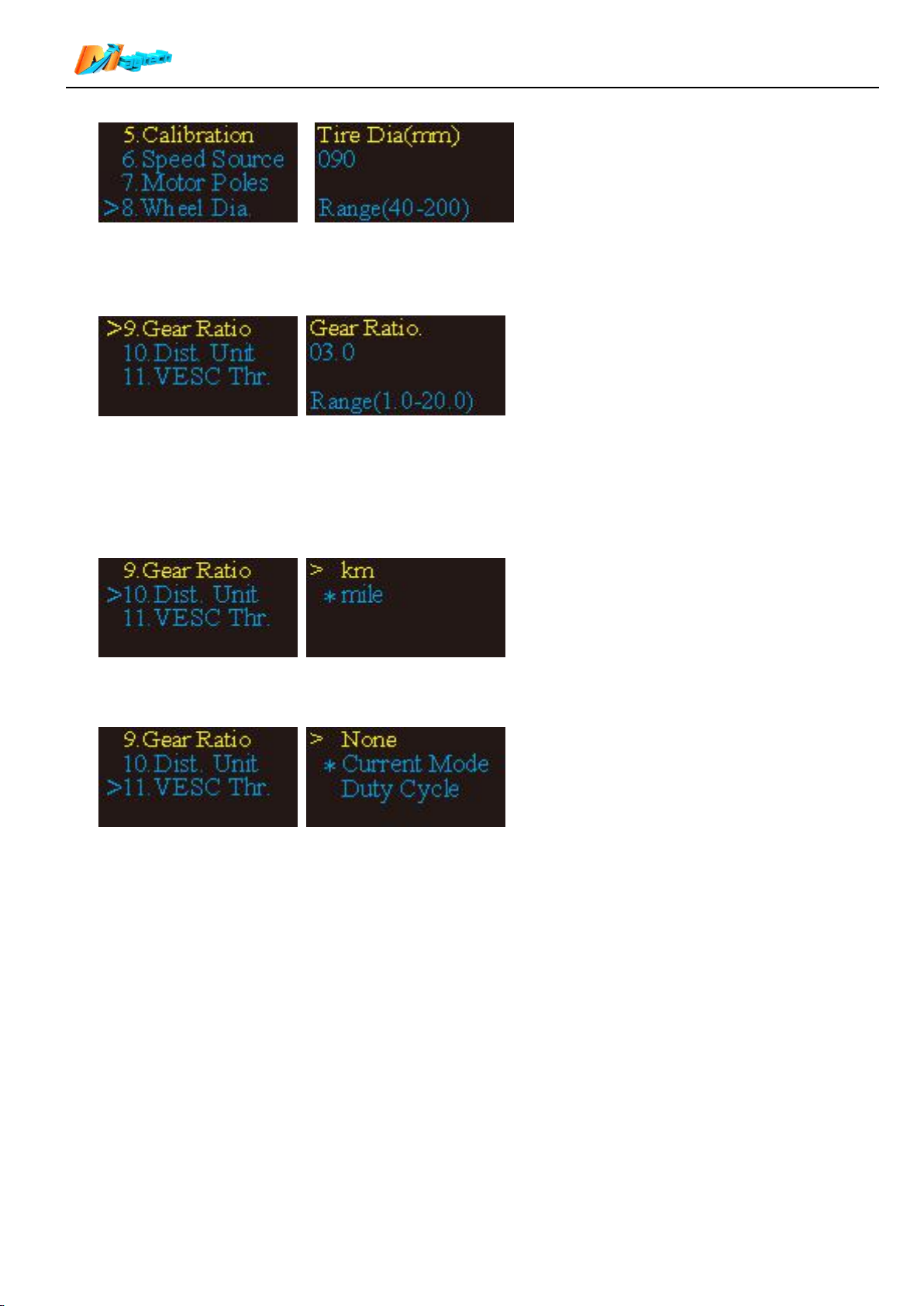
19.8 Wheel Dia
This data is only valid in Esk8 mode. It’s to calculate speed and distance. Please refer to “Item 10”.
Long Press function button to select digit; Short press function button to add number.
Press brake trigger to save number and return to main menu. 19.9 Gear Ratio
Gear Ratio=Motor RPM÷Propeller or Wheel RPM. It’s to calculate speed and distance. Please refer to “Item
10”.
Long Press function button to select digit; Short press function button to add number.
Press brake trigger to save number and return to main menu.
19.10 Dist. Uni
Available units: km and mile. After selecting, speed unit will change to KM/H and MPH correspondingly.
19.11 VESC Thr.
19.11.1 If select Current mode or Duty cycle mode, it will automaitcally open UART port communication.
After connecting hardware, please set following 2 parameters in VESC_TOOL:
APP Setting>>General>>APP to USE>>UART / PWM and UART;
APP Setting>>UART>>Baudrate 115200 bps
19.11.2 Current mode throttle of the VESC is controlled by the motor current. To get good throttle linearity,
the maximum current must be set in VESC_TOOL to match the maximum current actually needed.
Too low maximum current will cause too low speed even with top throttle and the maximum power of
the motor will not be reached. Too high maximum current will cause motor getting max speed with
50% throttle. 50%-100% throttle has no effect.
19.11.3 The benefit of the Current Mode is when release throttle, the motor is free to coast without risk, so
this is the common throttle mode for skateboards and surfboards.
19.11.4 In the Duty Cycle mode, the VESC takes the speed of the motor as the control target. When the
throttle is released to the initial position, the motor will stop immediately. It is possible to throw
people off skateboards or surfboards. This mode is only available for differential-controlled robotic
carts.
20. Charging
16/17
Page 17
Maytech Waterproof Remote Control User Manual_20191012 by Eric and Eileen
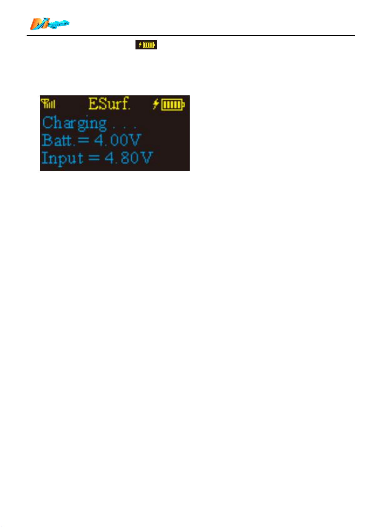
When remote battery icon has 2 or less bars, it needs to charge the remote. Please keep
remote dry when charging.
Connect wireless charger to power, put remote Charging Point right on the wireless charger; it will
automatically charge after 2 seconds.
Remote screen will show charger input voltage “Input” and current battery voltage “Batt.”.
When remote battery gets to 4.2V, it will stop charging automatically.The screen displays voltage data all
the time and will not shut down automatically. Please don’t put remote on charger for longtime after
full-charged!
Charging without supervision is prohibited!
When the remote control is not used, please charge it once a month, otherwise the battery life will be
shortened or even scrapped due to long-term power loss.
20. Firmware update (to be updated)
17/17
 Loading...