

Maytag Services ACE5302, P1331307M, UACE5302, P1331308M, DS30E2 Service Manual
...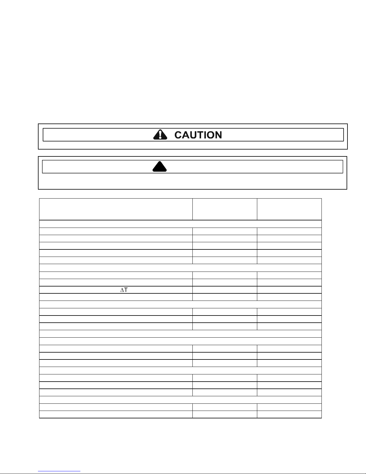
International Commercial Microwave—Technical Information
230 V, 50 Hz Models
ACE5302 P1331307M UACE5302 P1331308M
DS30E2 P1331309M UDS30E2 P1331310M
UCA2000NT2 P1331311M
• Due to possibility of personal injury or property damage, always contact an authorized technician for servicing or
repair of this unit.
• Refer to Service Manual RS5320016 for installation, operating, testing, troubleshooting, and disassembly
instruction.
All safety information must be followed as provided in Service Manual RS5320016.
!
To avoid the risk of electrical shock, personal injury or death; disconnect power to oven and discharge capacitor
before servicing, unless testing requires power.
Models ACE5302
Power Source
Voltage AC 230 VAC 230 VAC
Amperage (Single Unit) 16 A 13 A
Frequency 50 Hz 50 Hz
Single Phase, 3 wire grounded X X
Plug CEE 7/7 Schuko BS1363A
Power Output − Microwave
Nominal microwave energy (IEC705) 1000 Watts 1000 Watts
Traditional test method 900 Watts 900 Watts
Minimum temperature rise (∆T) 18ºF / 10ºC 18ºF / 10ºC
Operating Frequency 2450 MHz 2450 MHz
Power Consumption
Microwave only 1800 Watts 1800 Watts
Convection only 2700 Watts 2200 Watts
Combination 3400 Watts 3000 Watts
Dimensions
Cabinet (in / cm)
Width 49 cm (19 1/4") 49 cm (19 1/4")
Height 46 cm (18 1/4") 46 cm (18 1/4")
Depth 67 cm (26 1/4") 67 cm (26 1/4")
Oven Interior (in / cm)
Width 33 cm (13") 33 cm (13")
Height 27 cm (10 1/2") 27 cm (10 1/2")
Depth 38 cm (15") 38 cm (15")
Weight
Crated 46 kg. (102 lbs.) 46 kg. (102 lbs.)
Uncrated 43 kg. (95 lbs.) 43 kg. (95 lbs.)
WARNING
DS30E2
UACE5302
UDS30E2
UCA2000NT2
March 2005 1 16025975
©2005 Maytag Services

Component Testing Procedures
!
WARNING
To avoid risk of electrical shock, personal injury or death; disconnect power to oven and discharge capacitor
before servicing, unless testing requires power.
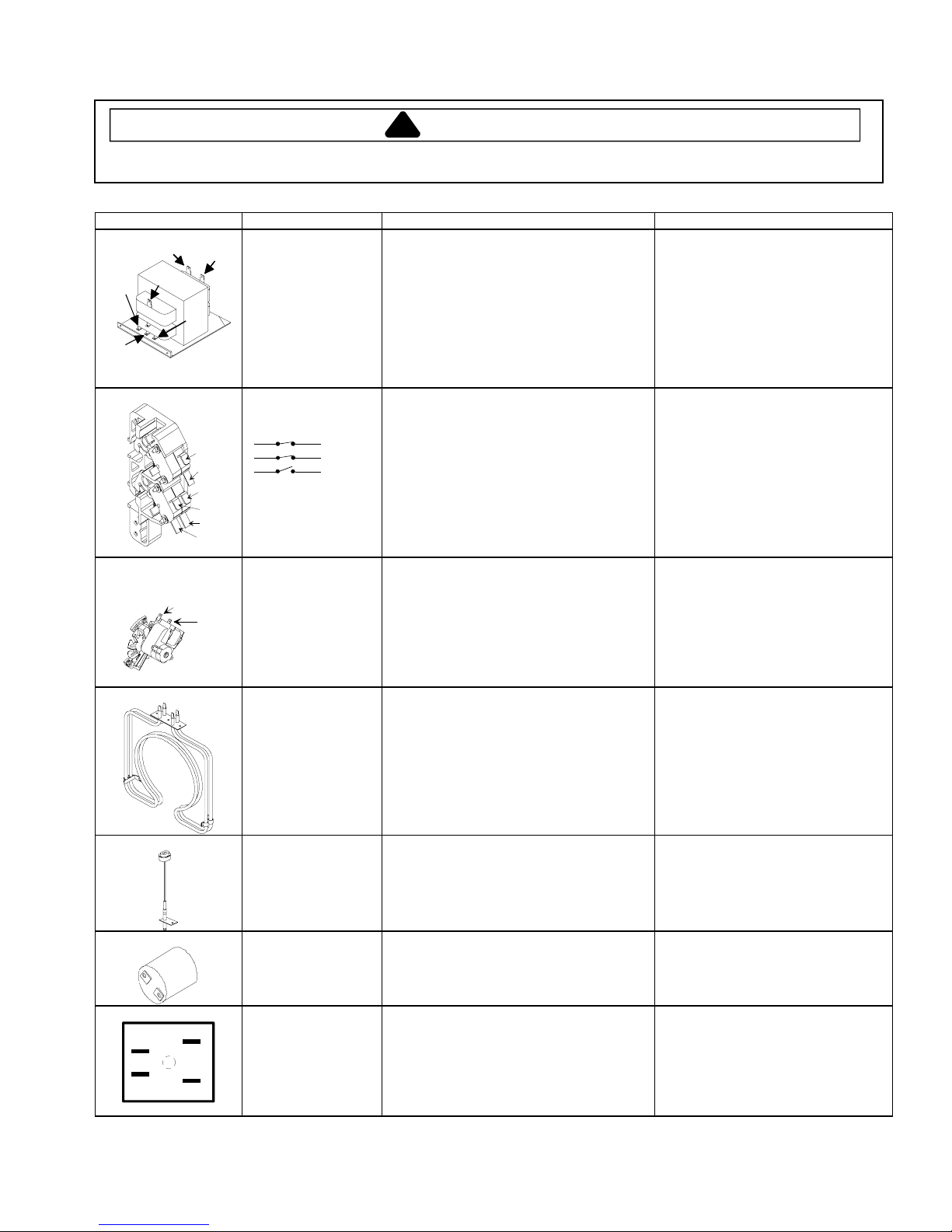
Illustration Component Test Results
MT2
MT1 GATE
Triac 1 (top) is for front element
Triac 2 (middle) is for rear element
Triac 3 (bottom) is for microwave
Thermal cutout Disconnect all wires from TCO.
Diode
Triac Disconnect wires to triac.
Capacitor
Snubber assembly Disconnect wires to snubber.
Magnetron
Microwave blower
motor
Measure resistance across terminals.
Control TCO..........................................
Fan TCO...............................................
Magnetron TCO ....................................
Heater Box Limiter ................................
Discharge Capacitor
Remove diode lead from capacitor and
connect ohmmeter.
Reverse leads for second test.
Measure resistance from:
MT1 to MT2 ..........................................
MT1 to Gate..........................................
MT2 to Gate..........................................
All terminals to ground ..........................
Measure voltage from:
MT1 to Gate
Discharge Capacitor
Remove wires from capacitor terminals and
connect ohmmeter, set on highest
resistance scale to terminals.
Also check between each terminal and
capacitor case.
Measure resistance across terminals.
Discharge Capacitor
Remove wires from magnetron and connect
ohmmeter to terminals. Also check
between each terminal and ground.
Remove all wires from motor.
Measure resistance across coil.
Open at 300°F (149°C) and
closed at 257°F (125°C)
Open at 125°F (52°C) and
closed at 160°F (71°C )
Open at 235°F (113°C) and
closed at 150°F (66°C)
Open at 351°F (177°C) and
closed at or below 18°F (-8°C)
Infinite resistance should be measured
in one direction and 50KΩ or more in
the opposite direction.
NOTE: Ohmmeter must contain a
battery of 6 volts minimum.
Caution - Do not operate oven with
wire to terminal MT2 removed.
Infinite
Approximately 15 Ω, then reverse
meter leads 30 Ω
Infinite
Infinite
0.8 VAC when energized. If no
voltage, check H.V. board and wiring.
Between Terminals: Meter should
momentarily deflect towards zero then
return to over 5 MΩ. If no deflection
occurs, or if continuous deflection
occurs, replace capacitor.
Terminal to Case: Infinite resistance
Infinite
Between Terminals: Less than 1 Ω
Each terminal to ground measures
Infinite resistance.
Note: This test is not conclusive. If
oven does not heat and all other
components test good replace the
magnetron and retest.
Approximately 30 Ω
16025975 March 2005
2
©2005 Maytag Services
Component Testing Procedures
4
!
WARNING
To avoid risk of electrical shock, personal injury or death; disconnect power to oven and discharge capacitor
before servicing, unless testing requires power.
Illustration Component Test Results
< 1.5 Ω
< 1.5 Ω
Infinite
Infinite
< 1 Ω
Approximately 70 Ω
Infinite
Infinite
Indicates continuity
Indicates continuity
Indicates continuity
Infinite
Approximately 20 Ω
COM
220
6
4
230
7
8
2
3
5
A
Transformer
5
Interlock switch
Door Closed
2
4
7
Convection blower
motor
Secondary
3
Primary
5
Monitor
8
Discharge Capacitor
Remove all wires from terminals.
Measure resistance from:
230 to COM
208 to COM
230 to Ground
208 to Ground
Terminal 5 to 6
Terminal 4 to Ground
Disconnect wires to switch.
With door open measure resistance from:
Terminal 2 to 3
Terminal 4 to 5
Terminal 7 to 8
With door closed measure resistance from:
Terminal 2 to 3
Terminal 4 to 5
Terminal 7 to 8
Remove wires from motor.
Measure resistance across
terminals A and B.
B
Blue
IN OUT
Brown
Blue
Brown
Heating element
assembly
Resistance thermal
device (RTD)
Lamp receptacle Test continuity of receptacle terminals. Indicates continuity with bulb
Line filter
Disconnect wires from terminals.
Measure resistance across heating
element.
Front element 1200 W ......................
Rear element 1500 W ......................
Front element 1100 W ......................
Rear element 1100 W ......................
Temperature
0°C (32°F)...................................................
177°C (350°F) .............................................
Disconnect wire from terminals.
Measure resistance of the following
terminals:
Blue to Blue............................................
Brown to Brown......................................
Indicates continuity
44 Ω
35 Ω
48 Ω
48 Ω
Resistance
1000 Ω
1654 Ω
screwed in.
< 1 Ω
< 1 Ω
March 2005 16025975
©2005 Maytag Services
3
Component Testing Procedures
!
WARNING
To avoid risk of electrical shock, personal injury or death; disconnect power to oven and discharge capacitor
before servicing, unless testing requires power.
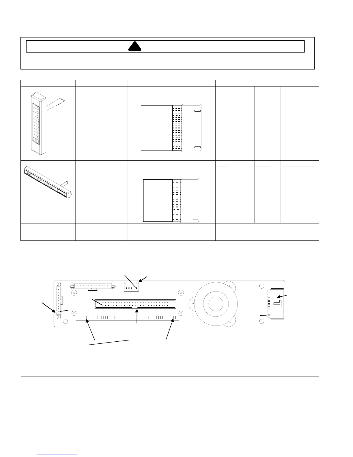
Illustration Component Test Results
Side touch panel
Top touch panel
Continuity is indicated as 100 Ω and
below.
1
Continuity is indicated as 100 Ω and
below.
Pad
1
2
3
4
5
6
7
8
9
0
Start
Stop/Reset
Pad
Preheat
Time Entry
Temp Entry
Power Level
Stage
Program Save
Hidden Pad
Trace
3 & 5
3 & 6
3 & 7
3 & 8
3 & 9
4 & 5
4 & 6
4 & 7
4 & 8
4 & 9
5 & 6
6 & 9
Trace
3 & 4
5 & 7
7 & 8
5 & 8
5 & 9
6 & 7
8 & 9
Measurement
Continuity
Continuity
Continuity
Continuity
Continuity
Continuity
Continuity
Continuity
Continuity
Continuity
Continuity
Continuity
Measurement
Continuity
Continuity
Continuity
Continuity
Continuity
Continuity
Continuity
1
Wire harness High voltage board
to display module
harness
Display board
Test continuity of wires. Indicates continuity
Interlock
Pin 1
Connector
Side
Touch
Panel
Pin 1
Pin 1
Connector
J5
3.5 VAC should be indicated whenever the oven is plugged into a power supply.
If voltage is present and no display is indicated, replace display board.
If no voltage is present, check wire harness connections and H.V. board.
16025975 March 2005
J1
H.V. board
Connector
Top
J6
J4
Pin 1
Touch
Panel
Connector
4
©2005 Maytag Services
Component Testing Procedures
!
WARNING
To avoid risk of electrical shock, personal injury or death; disconnect power to oven and discharge capacitor
before servicing, unless testing requires power.
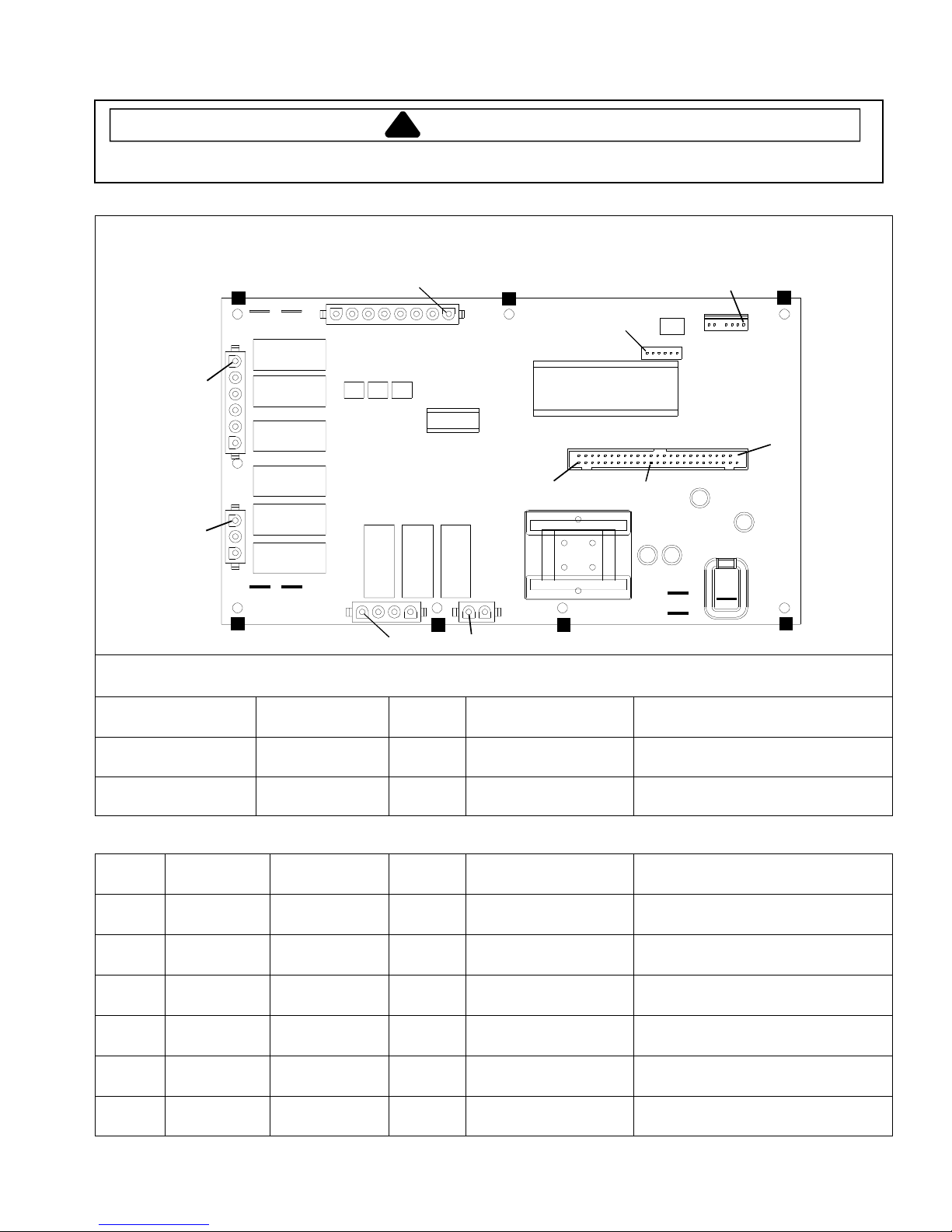
H.V. board
Pin 1
Pin 1
Clip
J4
J3
E6
E7
Pin 1
J7
Clip
Pin 50
J5
Pin 1
Pin 28
J6
Pin 1
Clip
J8
Pin 1
Clip
E5
E4
J2
Pin 1
Clip
Pin 1
J1
E3
E2
Clip
E1
Clip
In straight convection mode, both elements operate simultaneously.
In combination mode, the rear element will operate simultaneously with either the microwave or front element.
Function Test Set-Up Meter
Probe Placement Results
Setting
Input to H.V. board At H.V. board Volts J1 pin 1 (Black wire)
Line voltage
& J1 pin 2 (Red wire)
Output to display
board
Disconnect
J5 connector
Volts J5 pin 28 &
J5 pin 50
- 24 VDC
Relay Function Test Set-Up Meter
Probe Placement Results
Setting
K1 Cooling fan Disconnect
J2 connector
K2 Convection
motor
Disconnect
J2 connector
K3 Cavity light Disconnect
J2 connector
K4 Heater A
(front)
Disconnect
J3 connector
K7 Microwave Disconnect
J4 connector
K9 Heater B
(rear)
Disconnect
J4 connector
Ohms J1 pin 1 (Black wire)
& J2 pin 4
Ohms J1 pin 1 (Black wire)
& J2 pin 3
Ohms J2 pin 1 &
J2 pin 2
Test mode 5 off – no continuity
Test mode 5 on – < 1 Ω
Test mode 4 off – no continuity
Test mode 4 on – < 1 Ω
Test mode 6 off – no continuity
Test mode 6 on – < 1 Ω
Ohms E4 & J3 pin 3 Test mode 2 off – no continuity
Test mode 2 on – < 1 Ω
Ohms J4 pin 4 &
J4 pin 5
Test mode 3 off – no continuity
Test mode 3 on – < 1 Ω
Ohms E6 & J4 pin 1 Test mode 1 off – no continuity
Test mode 1 on – < 1 Ω
March 2005 16025975
©2005 Maytag Services
5
 Loading...