

Maytag Services AMV4204AAB, AMV4204AAQ, MMV4205AAB, AMV4204AAW, MMV4205AAW Technical Information
...
Domestic Microwave⎯Technical Information
Over-The-Range Convection Microwave Models
AMV4204AAB/W/Q MMV4205AAB/W/Q/S
• Due to possibility of personal injury or property damage, always contact an authorized technician for servicing or
repair of this unit.
• Refer to Service Manual 16023056 for detailed installation, operating, testing, troubleshooting, and disassembly
instructions.
CAUTION
!
All safety information must be followed as provided in Service Manual 16023056.
!
To avoid risk of electrical shock, personal injury or death; disconnect power to oven before servicing, unless
testing requires power.
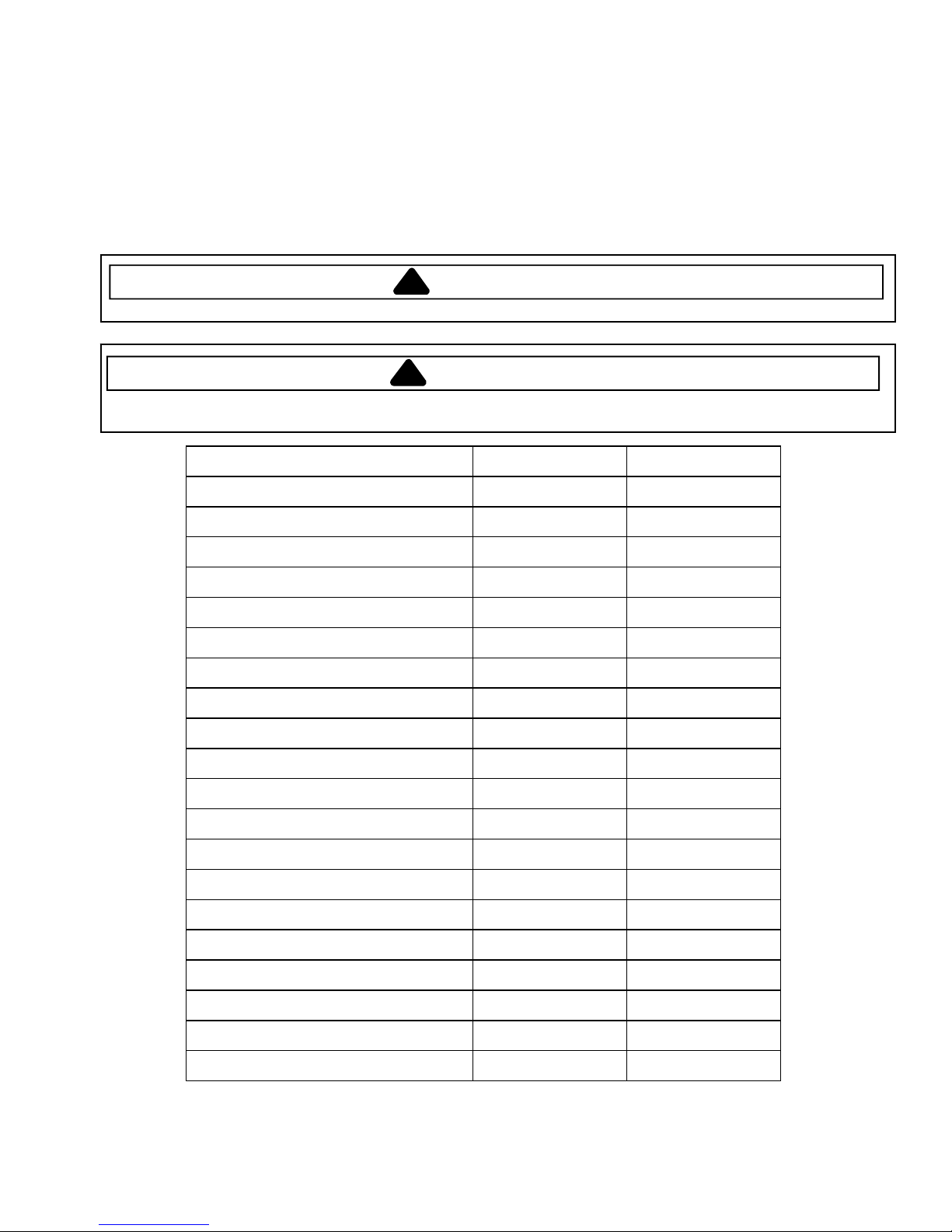
Power Source AMV4204AA* MMV4205AA*
Voltage AC 120 VAC 120 VAC
Amperage 20 A 20 A
Frequency 60 Hz 60 Hz
Single Phase, 3 wire grounded Yes Yes
Power Output
Nominal microwave energy (IEC705) 1150 Watts 1150 Watts
Operating frequency 2450 MHz 2450 MHz
Power Consumption
Microwave, lamp and vent fan 1700 Watts 1700 Watts
Dimensions, Exterior (Cabinet)
Width 29 15/16" 76 cm 29 15/16" 76 cm
Height 16 7/16" 42 cm 16 7/16" 42 cm
WARNING
Depth 15 3/8" 39 cm 15 3/8" 39 cm
Dimensions, Interior (Cavity)
Width 23 1/2" 60 cm 23 1/2" 60 cm
Height 10 3/16 " 26 cm 10 3/16 " 26 cm
Depth 14 1/2" 37 cm 14 1/2" 37 cm
Weight (approx.)
Uncrated 60 lbs 28 kg 60 lbs 28 kg
Crated 68 lbs 30 kg 68 lbs 30 kg
June 2005 16026270
©2005 Maytag Services
1
Component Testing Procedures
!
WARNING
To avoid risk of electrical shock, personal injury or death; disconnect power to oven before servicing, unless
testing requires power.
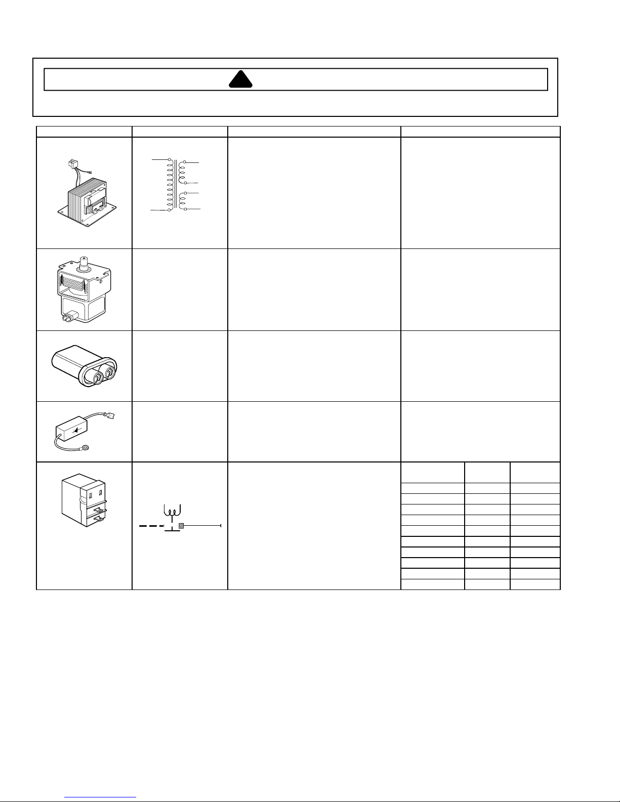
Illustration Component Test Procedure Results
High voltage
transformer
120 V
Primary
0 V
Magnetron
High Voltage
Capacitor
High Voltage Diode
Secondary
Filament
Relay 7
Discharge Capacitor
Disconnect connector and measure
continuity with meter on R x 1 scale:
Secondary ......................................
Filament..........................................
Primary (High & Low)......................
(Measure at room temperature, or 70° F/
22°C)
Measure continuity with meter on “High”
scale: Primary winding to ground ..............
Filament winding to ground .............
Discharge Capacitor
Remove wires from magnetron and
connect ohmmeter to terminals. Also
check between each terminal and ground.
Discharge Capacitor
Remove wires from capacitor terminals
and connect ohmmeter, set on highest
resistance scale to terminals.
Also check between each terminal and
capacitor case.
Discharge Capacitor
Remove diode lead from capacitor and
connect ohmmeter.
Reverse leads for second test.
Disconnect the leads. Place water in the
oven and select power levels 1 through
10. Check continuity between the
terminals of the relays.
Approximately 50-120 Ω
Less than 1 Ω
Less than 1 Ω
Infinite Ω
Infinite Ω
Between Terminals: Less than 1 Ω
Each terminal to ground: Infinite
resistance.
Note: This test is not conclusive. If
oven does not heat and all other
components test good replace the
magnetron and retest.
Between Terminals: Meter should
momentarily indicate several ohms,
then return to infinity. If no deflection
occurs, or if continuous deflection
occurs, replace capacitor.
Terminal to Case: Infinite resistance
Infinite resistance should be measured
in one direction and continuity in the
opposite direction.
NOTE: Ohmmeter must contain a
battery of 6 volts minimum.
Power Level
1 4 sec 18 sec
2 6 sec 16 sec
3 8 sec 14 sec
4 10 sec 12 sec
5 12 sec 10 sec
6 14 sec 8 sec
7 16 sec 6 sec
8 18 sec 4 sec
9 20 sec 2 sec
10 22 sec 0 sec
Cycle On
(Continuity)
Cycle Off
(Open)
16026270 June 2005
©2005 Maytag Services
2
Component Testing Procedures
!
WARNING
To avoid risk of electrical shock, personal injury or death; disconnect power to oven before servicing, unless
testing requires power.
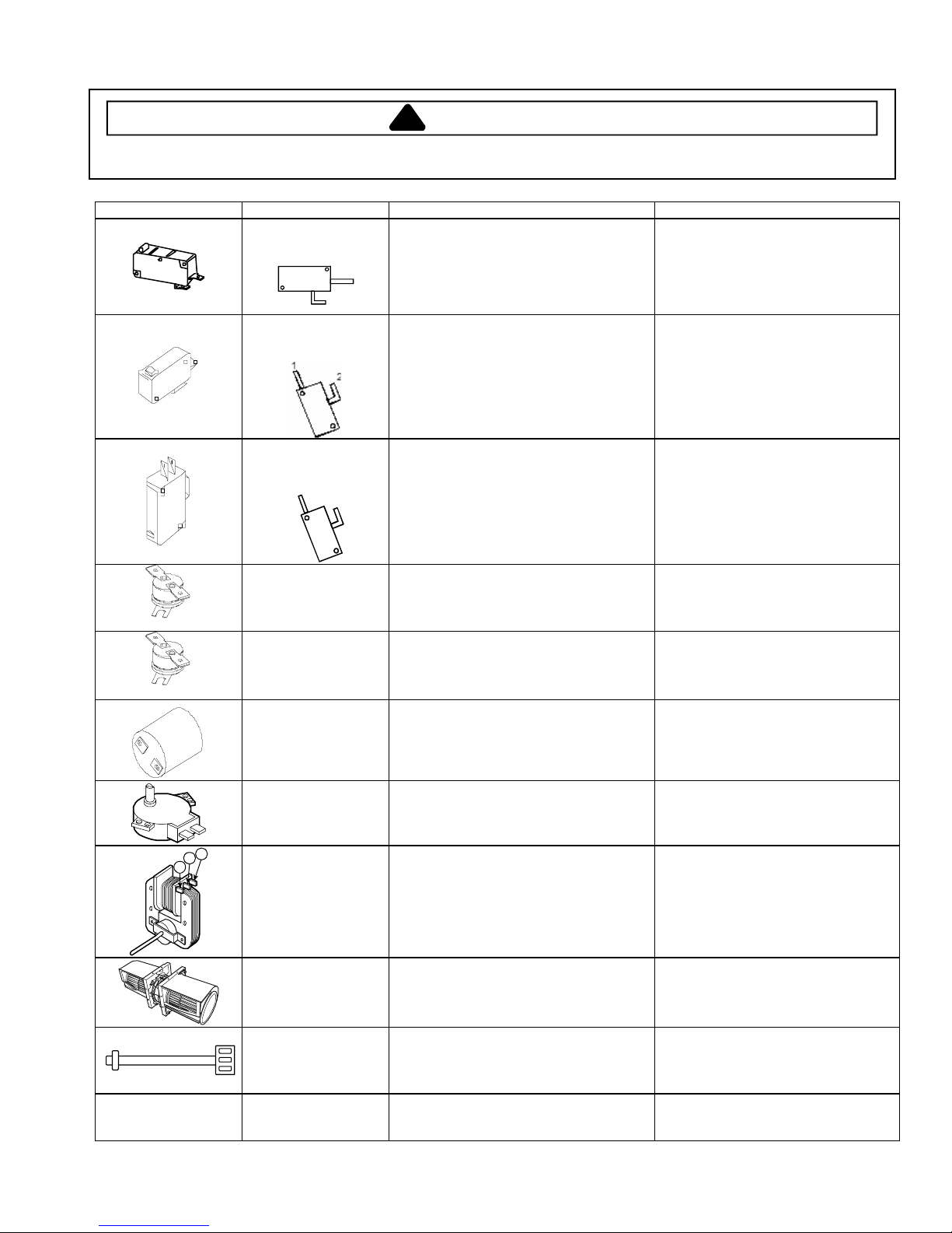
Illustration Component Test Procedure Results
Primary Interlock
Switch Test
(Top Switch)
Measure resistance between
terminals 1 and 2:
Door Open...................................................
1
Door Closed.................................................
Open
Continuity
2
Secondary Interlock
Switch Test
(Bottom Switch)
Measure resistance between
terminals 1 and 2:
Door Open...................................................
Door Closed.................................................
Open
Continuity
Interlock Monitor
Switch Test
(Middle Switch)
Magnetron Thermal
Cut-Out (Thermostat)
Oven Thermal CutOut (Thermostat)
Lamp receptacle Test continuity of receptacle terminals......... Indicates continuity if bulb is good and
1
2
Measure resistance between
terminals 1 and 2:
Door Open...................................................
Door Closed.................................................
Disconnect all wires from TCO.
Measure resistance across terminals.
Magnetron TCO ...........................................
Disconnect all wires from TCO.
Measure resistance across terminals.
Oven TCO....................................................
Continuity
Open
Open at 302°F (150°C) and closed at
32°F (0°C)
Open at 230°F (110°C)
Closed at 0°F (32°C)
installed.
Turntable Drive Motor
(Synchronous motor)
A
B
C
Fan motor Remove all wires from motor.
Ventilation Motor Remove all wires
Refer to Parts Manual
for proper power cord
part number.
Thermistor Remove connector from circuit board.
Power cord Measure resistance of wires ........................ Continuity on each wire.
June 2005 16026270
©2005 Maytag Services
Measure voltage across terminals ...............
Measure resistance across terminals...........
Measure resistance .....................................
Measure resistance across terminals...........
Measure resistance across pins 1 & 3.........
3
Approximately 120 VAC
Approximately 2-4 Ω
(All measurements approximate)
Across terminals A & C: 35-50 Ω
Across terminals A & B: 5-15 Ω
Infinite or several, motor is defective.
High Speed: Approximately 49-69 Ω
Low Speed: Approximately 97-117 Ω
Approximately 250-360 KΩ (70°F,
20°C ± 35°F, 2°C)
Verify polarity and grounding.

Component Testing Procedures
!
WARNING
To avoid risk of electrical shock, personal injury or death; disconnect power to oven before servicing, unless
testing requires power.
Illustration Component Test Procedure Results
FTP Connector
TOP
Touch Pad/Control
Panel
Model AMV4204A**
1
2
3
4
5
6
7
8
9
10
11
12
13
Removal of Touch
Pad/Control Panel is
required to perform test.
Check for continuity.
When touched: Less than
400
Ω
When not touched: More
than 1 mega
Ω
Pad
1
2
3
4
5
6
7
8
9
0
Popcorn
Baked Potato
Beverage
Cook
Reheat
Poultry
Soften
Melt
Auto Defrost
Time Defrost
Rapid Defrost
Clock
Cook Time
Control Setup
Power Level
Add 30 Sec.
Hold Warm
Stop/Clear
Enter/Start
Custom Program
Kitchen Timer
Light Timer
Vent Hi/Lo/Off
Turntable On/Off
Light Hi/Lo/Off
Trace
8 & 1
8 & 2
8 & 3
8 & 4
8 & 5
8 & 6
8 & 7
13 & 5
13 & 6
13 & 7
11 & 1
9 & 6
9 & 7
11 & 2
11 & 3
10 & 4
10 & 6
10 & 7
11 & 4
11 & 6
11 & 7
12 & 5
9 & 2
12 & 1
13 & 1
11 & 5
12 & 2
13 & 3
13 & 4
9 & 3
12 & 4
9 & 5
10 & 1
12 & 3
10 & 3
Measurement
Continuity
Continuity
Continuity
Continuity
Continuity
Continuity
Continuity
Continuity
Continuity
Continuity
Continuity
Continuity
Continuity
Continuity
Continuity
Continuity
Continuity
Continuity
Continuity
Continuity
Continuity
Continuity
Continuity
Continuity
Continuity
Continuity
Continuity
Continuity
Continuity
Continuity
Continuity
Continuity
Continuity
Continuity
Continuity
16026270 June 2005
©2005 Maytag Services
4

Component Testing Procedures
!
WARNING
To avoid risk of electrical shock, personal injury or death; disconnect power to oven before servicing, unless
testing requires power.
Illustration Component Test Procedure Results
FTP Connector
TOP
Touch Pad/Control
Panel
Model MMV4205A**
1
2
3
4
5
6
7
8
9
10
11
12
13
Removal of Touch
Pad/Control Panel is
required to perform test.
Check for continuity.
When touched: Less than
400
Ω
When not touched: More
than 1 mega
Ω
Pad
1
2
3
4
5
6
7
8
9
0
Popcorn
Baked Potato
Beverage
Cook
Reheat
Poultry
Soften
Melt
Auto Defrost
Time Defrost
Rapid Defrost
Clock
Cook Time
Control Setup
Power Level
Add 30 Sec.
Hold Warm
Stop/Clear
Enter/Start
Custom Program
Kitchen Timer
Light Timer
Vent Hi/Lo/Off
Vent Auto Time Set
Turntable On/Off
Light Hi/Lo/Off
Trace
8 & 1
8 & 2
8 & 3
8 & 4
8 & 5
8 & 6
8 & 7
13 & 5
13 & 6
13 & 7
11 & 1
9 & 6
9 & 7
11 & 2
11 & 3
10 & 4
10 & 6
10 & 7
11 & 4
11 & 6
11 & 7
12 & 5
9 & 2
12 & 1
13 & 1
11 & 5
12 & 2
13 & 3
13 & 4
9 & 3
12 & 4
9 & 5
10 & 1
10 & 5
12 & 3
10 & 3
Measurement
Continuity
Continuity
Continuity
Continuity
Continuity
Continuity
Continuity
Continuity
Continuity
Continuity
Continuity
Continuity
Continuity
Continuity
Continuity
Continuity
Continuity
Continuity
Continuity
Continuity
Continuity
Continuity
Continuity
Continuity
Continuity
Continuity
Continuity
Continuity
Continuity
Continuity
Continuity
Continuity
Continuity
Continuity
Continuity
Continuity
June 2005 16026270
©2005 Maytag Services
5

Component Testing Procedures
!
To avoid risk of electrical shock, personal injury or death; disconnect power to oven before servicing, unless
testing requires power.
WARNING
Power Test (Traditional Test Method)
Test equipment required is Amana power test kit R0157397 (Fahrenheit), or
Menumaster power test kit M95D5 (Celsius).
1. Fill the plastic container to the 1000 ml. line with cool tap water.
2. Using the thermometer; stir the water, measure, and record the water temperature.
Initial water temperature should be approximately 60°F (16°C).
3. Place container on the center of the oven shelf and heat the water for
33 seconds for ovens with more than 1550 watts or 63 seconds for ovens with less than 1550 watts.
NOTE: Use a watch second hand, not the oven timer.
4. Stir the water, measure and record the temperature of the water after heating time is complete.
5. Subtract the starting water temperature (Step 2), from the ending water temperature (Step 4) to obtain the
temperature rise (∆T).
6. See the Traditional Power Test Temperature Chart below.
NOTES: •The IEC-705 test method requires precision measurements and equipment. It is not practical to perform
the IEC test in the field. To convert the traditional power test results to the approximate IEC-705 rating,
take the traditional power test results and add 100 watts per magnetron for the unit being tested.
Example: 1050 ⎯ watts output using the traditional power test
+ 100
1150 ⎯ Approximate IEC-705 results
•Always perform power test three times for accuracy, changing the water after each test is performed.
•Variation or errors in the test procedure will cause a variance in the temperature rise. Additional power
tests should be made if temperature rise appears marginal.
•Low line voltage will cause lower temperature rise.
⎯ watts (1 magnetron X 100 watts)
Traditional Power Test Temperature Chart
SIXTY-THREE (63) SECONDS run time chart for units less than 1550 Watts cooking power
Fahrenheit Celsius
∆T Cooking ∆T Cooking ∆T Cooking ∆T Cooking
(°F) Power Output (°F) Power Output (°C) Power Output (°C) Power Output
16 620 23 891 7 490 15 1050
17 659 24 930 8 560 16 1120
18 697 25 969 9 630 17 1190
19 736 26 1007 10 700 18 1260
20 775 27 1046 11 770 19 1330
21 814 28 1085 12 840 20 1400
22 852 29 1124 13 910 21 1470
14 980 22 1540
16026270 June 2005
©2005 Maytag Services
6

Wiring Diagram and Schematic
!
WARNING
To avoid risk of electrical shock, personal injury or death; disconnect power to oven before servicing, unless
testing requires power.
WH
YL
YL
WH
BK
BN
BK
WH
WH
CAPACITOR
H.V.DIODE
MAGNETRON
BN
RD
H.V.
H.V.
F
FA
AMV4204AAB/W/Q, MMV4205AAB/W/Q/S Schematic Diagram, Series 10
June 2005 16026270
©2005 Maytag Services
7

Wiring Diagram and Schematic
!
To avoid risk of electrical shock, personal injury or death; disconnect power to oven before servicing, unless
testing requires power.
WARNING
WARNING
POWER MUST BE DISCONNECTED
BEFORE SERVICING THIS APPLIANCE
AMV4204AAB/W/Q Schematic Diagram, Series 11
16026270 June 2005
©2005 Maytag Services
8

Wiring Diagram and Schematic
!
To avoid risk of electrical shock, personal injury or death; disconnect power to oven before servicing, unless
testing requires power.
WARNING
WARNING
POWER MUST BE DISCONNECTED
BEFORE SERVICING THIS APPLIANCE
MMV4205AAB/W/Q/S Schematic Diagram, Series 11
June 2005 16026270
©2005 Maytag Services
9
 Loading...