

Maytag Services MDE5500A, MDE6800A Service Manual
27" Domestic Dryer
⎯⎯
⎯Technical Information
⎯⎯
MDE5500A*, MDE6800A*
• Due to possibility of personal injury or property damage, always contact an authorized technician for servicing or
repair of this unit.
• Refer to Service Manual 160231 10 for detailed installation, operating, testing, troubleshooting, and disassembly
instructions.
CAUTION
!
All safety information must be followed as provided in Service Manual 160231 10.
!
T o avoid risk of electrical shock, personal injury or death; disconnect power to dryer before servicing, unless
testing requires power.
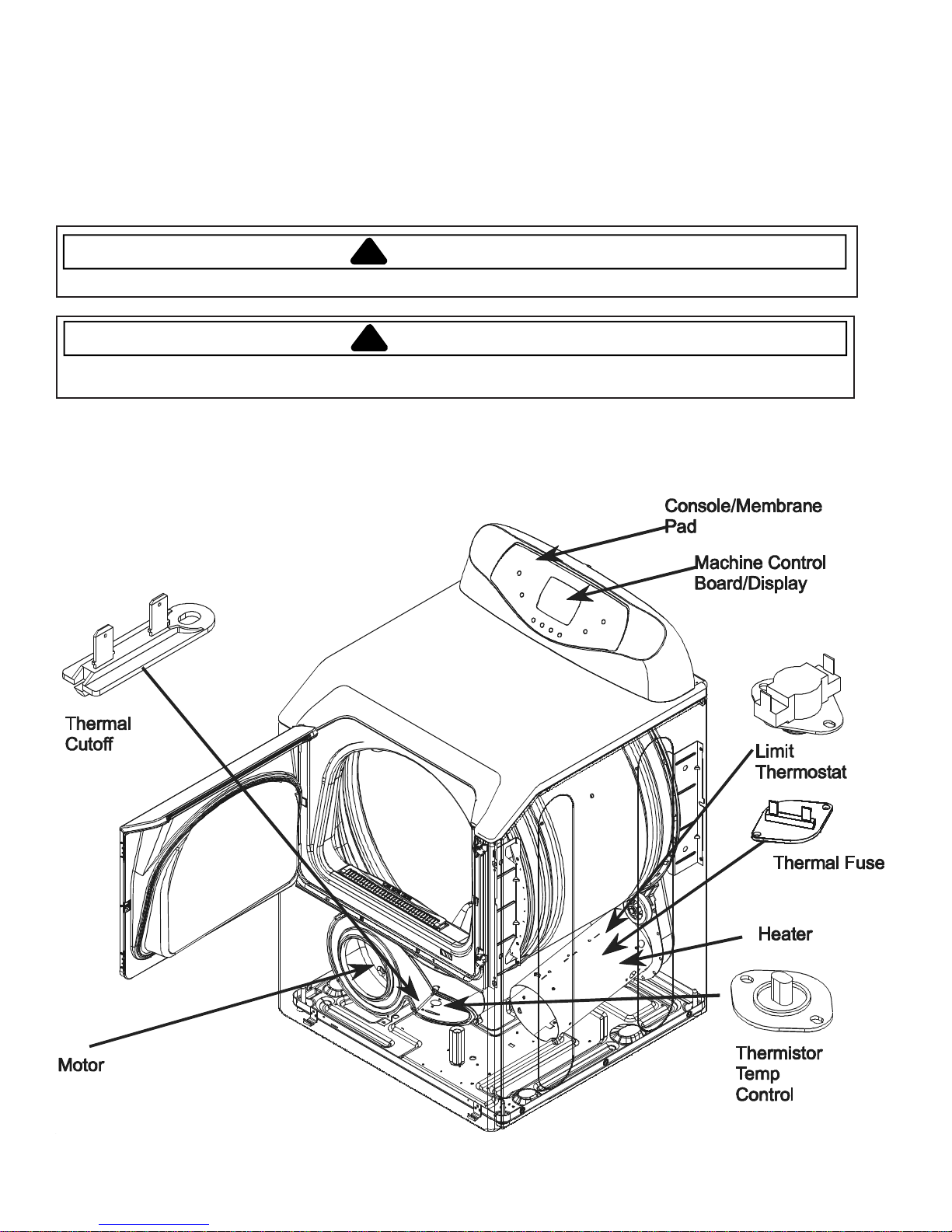
Maytag LED Electric Dryer
WARNING
September 2006 1 16027056
©2006 Maytag Services
Troubleshooting Procedures
g
!
WARNING
T o avoid risk of electrical shock, personal injury or death; disconnect power to dryer before servicing, unless
testing requires power.
Maytag Dryer MDE6800A, MDE5500B
• Due to po ssibility of per sonal injury or property damage, always contact an authorized technician for servicing
or repair of this unit.
Will Not Run
Will not start or run:
• All wires are hooked up to their corresponding
terminals.
• Dryer is plugged in.
• Blown fuse or circuit breaker.
• Door switch functional...door closed.
• Start/Pause switch functional.
• Control Board operational.
• Drive motor functional.
• Blown thermal fuse.
Motor ru ns/ tumbler will no t t urn:
• Belt off or broken/damaged.
• Idler tension spring too weak or stretched.
• Idler pulley jammed or stuck.
Runs a few minutes and then stops:
• Lint buildup around drive motor.
• Low voltage present.
• Blower impeller blocked in blower
housing.
• Drive motor - start switch contacts stuck closed.
Blows fuses or trips circuit breaker:
• The amperage readings are at 240 volts. One line
will be 24 amps and the other line will be 21 amps .
The neutral line will be at 3 amps. If the above
amperages are present, then the house wiring,
fuse box or circuit breaker should be suspect.
• Shorted heating element to housing.
• Incorrect wiring or a wire shorting to ground.
• Drive motor winding shorting to ground.
Will Not Dry
Will not heat (motor runs):
• Open heating element.
• Hi-Limit trips easily or is open.
• Regulating thermostat trips easily or is open.
• Membrane switch open.
• Drive motor centrifugal start switch not allowing
voltage to gas valve or heating element.
Improper drying/clothes wrinkled/ rough
texture/long dry time:
• Lint filter is not clean.
• Restriction in exhaust.
• Outside exhaust hood damper door stuck closed.
• Exhaust too long, too many elbows, flex ductwork
installed.
• Poor makeup air available for the dryer.
• Incorrect tumbler speed. Tumbler belt slipping.
• Blower impeller bound; check for foreign material
in blower area.
• Customer overloading dryer.
• Check clothing labels for fabric content and cycle
selected.
• Clothes too wet due to insufficient spin out by
washer.
Will Not Shu t Off
Short in Sensor Circuit.
Check Membrane Pad.
Check Electronic Control Board.
Troubleshooting the electronic
control cir c uit:
• Check for m iswiring of the electrical connector at
the electronic control board.
• Does not shut off, then the problem is in the
electronic control unit. Disconnect the sensor wire
from the sensor bar. If the dryer runs for about 20
minutes, then shuts down or the timer advances,
then the electronic control unit is good and the
problem lies in the sensor bar.
• Check sensor for continuity. If found, replace
sensor bar or clean with alcohol. Some fabric
softener sheets w ill coat the sensor bars.
Noisy and/Or Vibration
• Thumping Check for loose tumbler baffle, rear
tumbler roller(s) worn or misaligned, out-of-round
tumbler or high weld seam on tumbler.
• Ticking Check for loose wire harness or object
caught in blower wheel area.
• Scraping Check for front or rear bulkhead felt seal
out of position or worn tumbler front bearings.
• Roaring Check for blower wheel rubbing on blower
housing or bad motor bearings.
• Popping or squealing sound. Check for a sticky
or frayed belt.
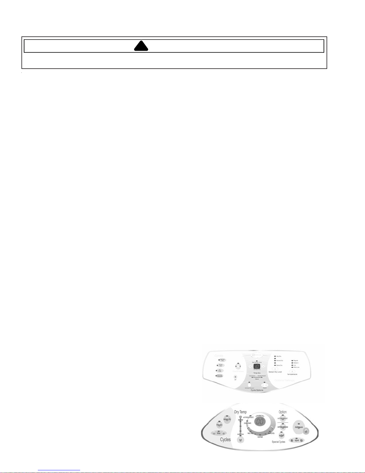
Control Configuration
This Trouble Shooting guide illustrates how the
software works with the 13 and 15 key membrane
switches. The section on Accessing Diagnostic Codes
includes instruction for use with older control boards.
13 Key Membrane
15 Key Membrane
16027056 2 September 2006
©2006 Maytag Services
Troubleshooting Procedures
T o avoid risk of electrical shock, personal injury or death; disconnect power to dryer before servicing, unless
testing requires power.
Service Mode
This mo de provides Service Personnel the ability to
verify the operation of the dryer.
The Service Mode can be implemen ted in the middle of
any dry cycle. While in the Ser v ice Mode, the
Technician ca n start special diagnostic t ests such as a
System Check Mode, Membra ne Pad Check, Display
Software versio n number and display diagnostic/help
code listings.
and
Time (^)
- 13
- 13 Key Membrane.
- 15 Key
Test/Function
Display list of
diagnostic codes.
To sequence thru
the diagnostic
and help codes.
Display revision
number
View current
cycle temperature
in Celsius
Start or pause
cycle running but
remain in
diagnostic mode.
Enter Service Mode:
Press
Air Fluff
or
Air Fluff
keys for 3 sec onds, or until a beep is heard . The
machine will now be in Se rvice Mode and “d” will be
displayed.
Exit Service Mode
Press the OFF key to exit Service Mode or repeat the
Air Fluff and Time (+) sequence.
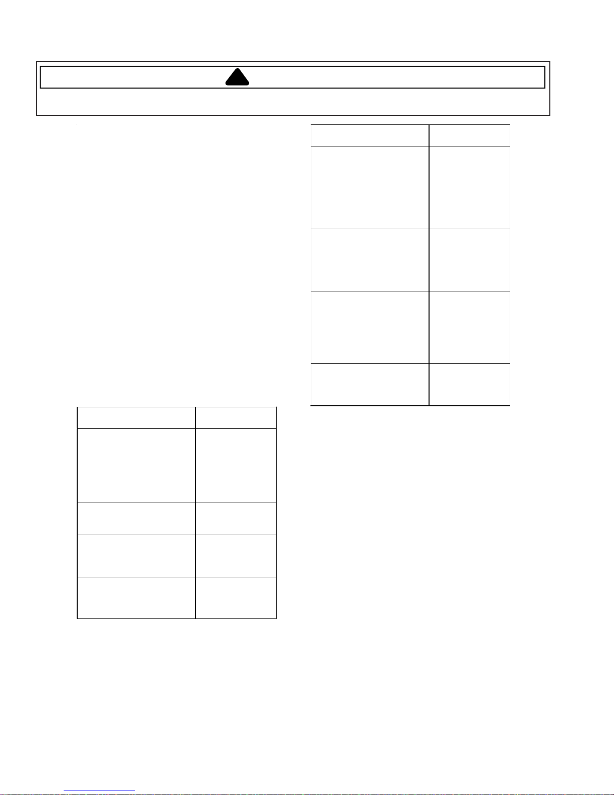
Diagnostic Tests
The following ta ble lists the various tests available while
in the Service Mode, which can be accessed by
pressing the following keys:
Key Press Special
Wrinkle release
Then press
Temperature (^) - 13 Key
or
Dry Temp (^) - 15 Key
Time (v) - 13 Key
or
Time (-) - 15 Key
Sensor Dry Level (^)
Key
or
Very Dry (<) - 15 Key
Start/Pause
System Check Mode
While in Service Mode, pressing the
Air Fluff and Signal (+) - 13 Ke y Membrane
or
Air Fluff and Signal (+) - 15 Ke y Membrane
keys for 3 sec onds, will put the dryer into the System
Check m ode and "SC" will display. The following table
lists the various functions based on the keys being
pressed.
System Check Mode Table
and
Time (+)
September 2006 3 16027056
©2006 Maytag Services
!
Membrane.
WARNING
Key Pressed: Function
Sensor Dry
Start/Pause
Temperature (^)
or
Dry Temp (^)
Sensor Dry Level (^) - 13
Key
or
Very Dry (<) - 15 Key
Performed
Enable sensor
dry circuit (sense
dry LED) when
short circui t is
detected acros s
the sensor bars
the normal dr y
LED will turn on.
Cycles the motor
relay on/off.
When the motor
is running the
start/pause LED
is on.
- 13 Key
- 15 Key
Membrane Pad Check
The membrane check turns all the embedded LED’s on.
All the LED’s can the n be toggled off by pressing t he
key associated with the LED.
While in
Air Fluff and Sensor Dry - 13 Key
or
Air Fluff and Sensor Dry - 15 Key
keys for 2 sec onds, will start a Memb rane Pad Switch
Test. To exit the test at any point, pres s the same keys
again for 2 seconds or press the OFF key to exit
Service Mode.
System Check
If motor is
running, cycles
the heater/gas
valve on/off.
When the heater
is regular temp
LED is on.
View current
cycle temperature
in Celsius.
Mode, pressing the
 Loading...