

Page 1
INSTALLATION
INSTRUCTIONS
CommerCial StaCked WaSher/dryer
GaS or eleCtriC
INSTRUCTIONS
D’INSTALLATION
laveuSe/SéCheuSe SuperpoSéeS
à uSaGe CommerCial
à Gaz ou éleCtrique
INSTRUCCIONES
DE INSTALACIÓN
lavadora/SeCadora ComerCialeS
TABLE OF CONTENTS
Page
Stacked Washer/Dryer Safety
Tools & Parts
Alternate Parts and Accessories ........ 6
Dimensions/Clearances
Stacked Washer/Gas Dryer
Installation Requirements
Stacked Washer/Electric Dryer
Installation Requirements
Dryer Venting Requirements
Dryer Gas Supply Requirements
Installing Stacked Washer/Dryer
Washer Drain System
Electric Dryer Electrical
Connections
Leveling
Reversing Dryer Door Swing
Stacked Washer/Dryer
Maintenance Instructions
If You Need Assistance
Electronic Control Setup
Instructions
Warranty
W10335465B
........................................ 5
........................ 22
....................................... 23
............................................... 27
........................................ 33
............................................. 39
............. 2
...................... 7
................... 8
................. 11
............ 15
...... 18
...... 19
............. 29
.................. 31
...................... 32
apiladaS a GaS o eléCtriCaS
TABLE DES MATIÈRES
Page
Sécurité de la laveuse/sécheuse
superposées
Outils et pièces
Pièces supplémentaires
et accessoires
Dimensions/Distances
de dégagement
Exigences d’installation pour
la laveuse/sécheuse à gaz
superposées
Exigences d’installation pour la
laveuse/sécheuse électriques
superposées
Exigences concernant
l’évacuation de la sécheuse
Spécications de l’alimentation
en gaz de la sécheuse
Installation de la laveuse/sécheuse
superposées
Système d’évacuation
de la laveuse
Raccordements de la sécheuse
électrique
Nivellement
Inversion du sens d’ouverture
de la porte de la sécheuse ................. 68
Instructions d’entretien de la
laveuse/sécheuse superposées
Si vous avez besoin d’assistance
Instructions de réglage du tableau
de commande électronique
Garantie
....................................... 40
.................................. 43
.................................... 44
.................................. 45
....................................... 46
..................................... 49
............. 54
....................... 57
...................................... 58
....................................... 61
........................................... 62
......................................... 66
....... 70
..... 71
.............. 72
.............................................. 79
www.maytagcommerciallaundry.com
ÍNDICE
Página
Seguridad de la lavadora/
secadora apiladas
Herramientas y piezas
Piezas y accesorios adicionales ...... 84
Dimensiones y espacios libres
Requisitos de instalación de la
lavadora/secadora a gas apiladas
Requisitos de instalación de la
lavadora/secadora eléctricas
apiladas
Requisitos de ventilación
de la secadora
Requisitos del suministro
de gas de la secadora
Instalación de la lavadora/
secadora apiladas
Sistema de desagüe
de la lavadora
Conexiones eléctricas
de la secadora eléctrica
Nivelación
Cómo invertir el cierre
de la puerta de la secadora
Instrucciones de mantenimiento
de la lavadora/secadora apiladas
Si necesita ayuda
Instrucciones de programación
del control electrónico
Garantía
.............................................. 89
.......................................... 106
............................................ 120
.............................. 80
....................... 83
......... 85
... 86
................................... 94
....................... 97
.............................. 98
................................... 101
................. 102
............. 108
... 110
............................. 111
.................... 112
Page 2
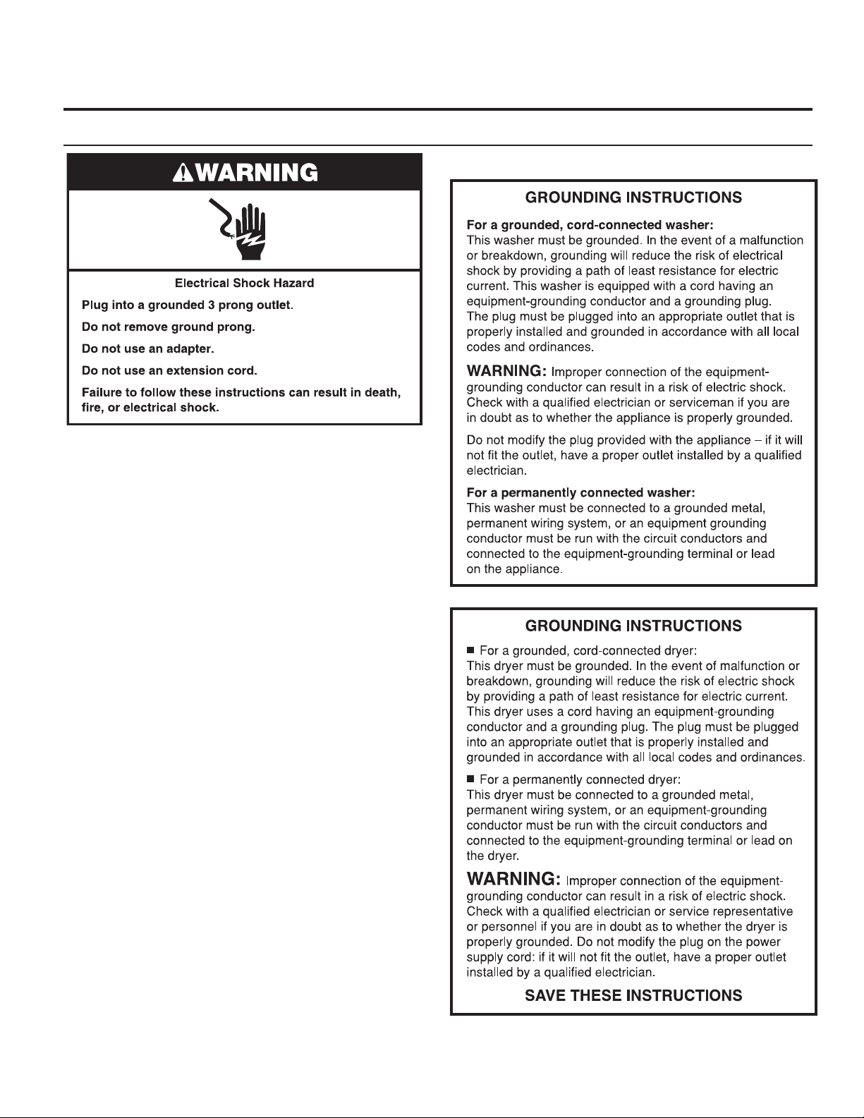
STACKED WASHER/DRYER SAFETY
n It is recommended that the owner post, in a prominent location, instructions for the customer’s use in the event the customer
smells gas. This information should be obtained from your gas supplier.
n Post the following warning in a prominent location.
2
Page 3
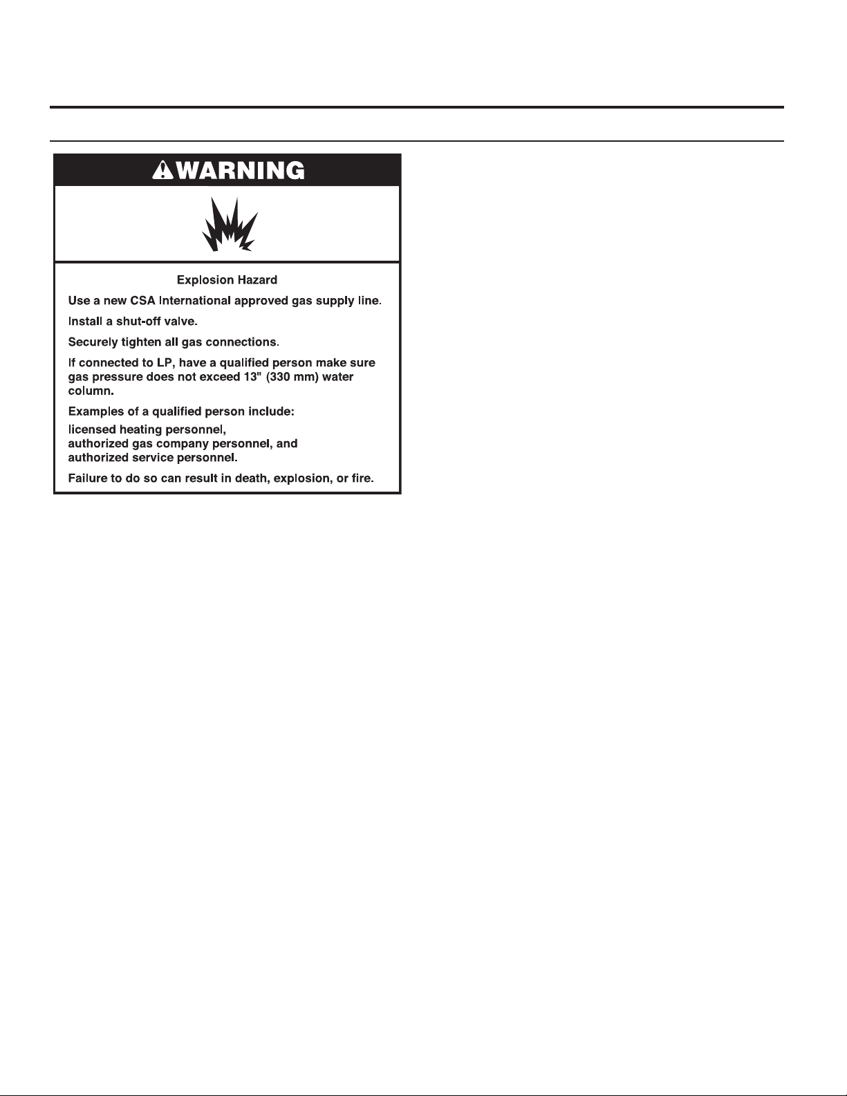
STACKED WASHER/DRYER SAFETY
3
Page 4
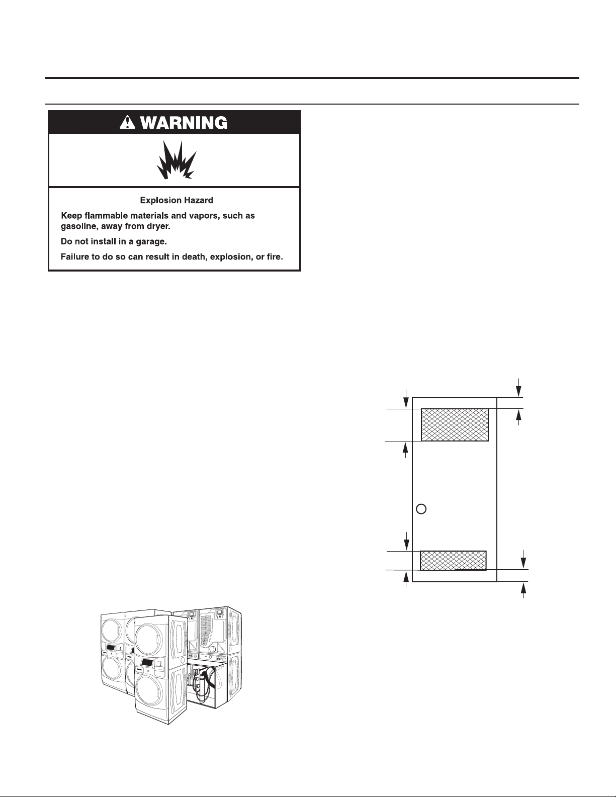
STACKED WASHER/DRYER SAFETY
4
Page 5
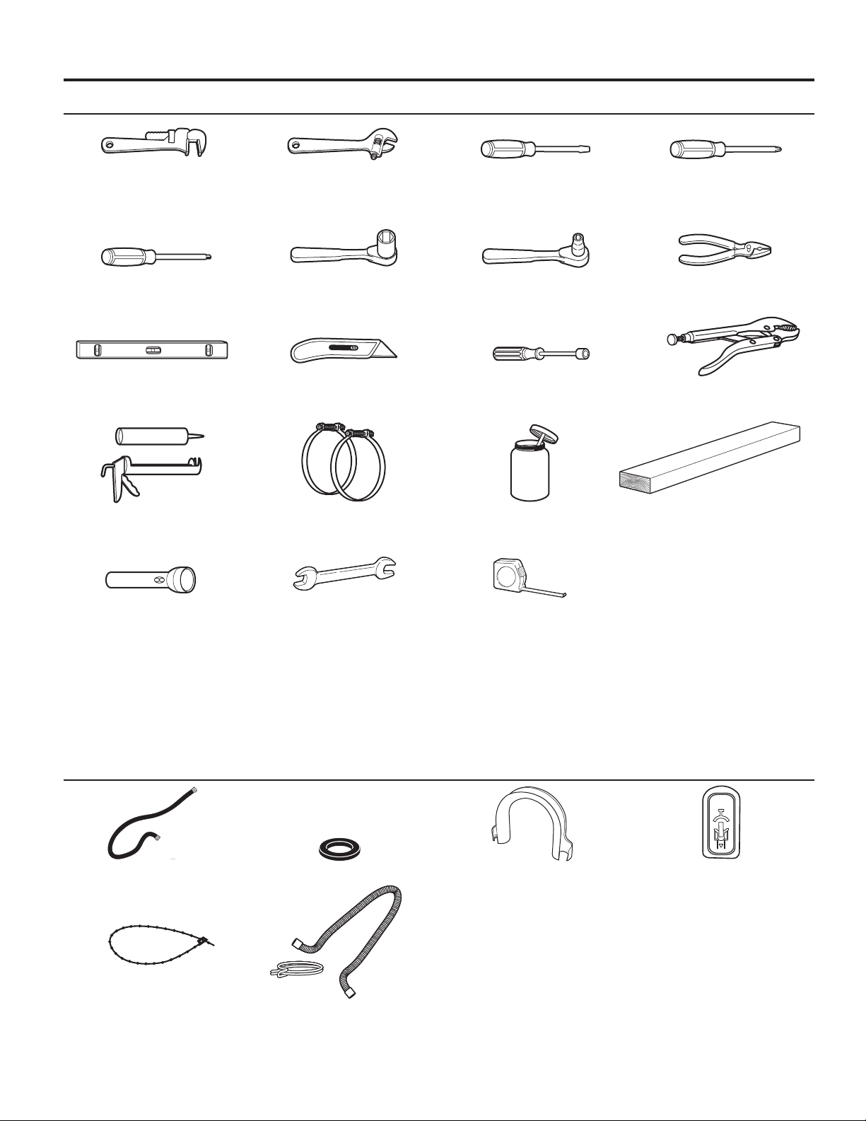
TOOLS & PARTS
Tools Needed:
8" (203 mm) 8" (203 mm) or 10" (254 mm) at-blade screwdriver phillips screwdriver
or 10" (254 mm) adjustable wrench
pipe wrench that opens to 1" (25 mm)
Torx®† T-20 security 1" (25 mm) hex-head 5⁄16" socket wrench pliers
screwdriver or bit socket wrench (that open to 19/16" [39 mm])
level utility knife 1/4" (6 mm) nut driver locking pliers
caulk gun and caulk vent clamps pipe-joint compound 27" (686 mm) wood block
(for installing new exhaust vent) suitable for gas type
ashlight (optional) 1/2" (13 mm) and 9/16" ruler or measuring tape
(14 mm) open-end wrenches
Parts Supplied:
water inlet hoses (2) inlet hose washers (4) U-shaped hose form transit bolt hole plug (4)
beaded tie strap
drain hose/clamp
†® TORX is a registered trademark of Saturn Fasteners, Inc.
5
Page 6
ALTERNATE PARTS AND ACCESSORIES
Alternate Parts
Your installation may require additional parts. If you are
interested in purchasing one of the items listed here, call
the toll-free number in the “If You Need Assistance” section.
If You Have You Will Need to Buy
Overhead sewer Standard 20 gal. (76 L) 39"
1" (25 mm) standpipe 2" (51 mm) diameter to 1" (25 mm)
Drain hose too Extension Drain Hose Part
short Number 285863
Connector Kit Part Number 285835
Lint clogged drain Drain Protector Part Number 367031
Connector Kit Part Number 285835
Floor drain system Siphon break, Part Number 285834
Water faucets 2 longer water ll hoses:
beyond reach 6 ft. (1.8 m) 90° bend hose
of ll hoses Part Number 76314
10 ft. (3.0 m) Part Number 350008
(990 mm) tall drain tub or utility
sink, sump pump and connectors
(available from local plumbing
suppliers)
diameter Standpipe Adapter
Part Number 3363920
Connector Kit Part Number 285835
Connector Kit (x2) Part Number
285835
Extension Drain Hose Part
Number 285863
Accessories
Enhance your washer/dryer with these premium accessories.
For more high-quality items or to order,
call 1-800-901-2042, or visit us at
www.maytag.com/accessories.
In Canada call: 1-800-807-6777 or visit us at
Part Number Accessory
8212526 Washer drip tray, ts under all
31682 All-purpose appliance cleaner
1903WH Laundry supply storage cart
279818 3-way dryer venting kit
285834 Siphon break kit
www.whirlpoolparts.ca.
6
Page 7
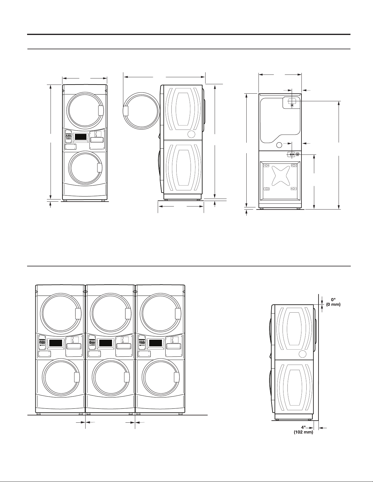
DIMENSIONS/CLEARANCES
(25 mm)
Dimensions
Front View Side View Back View
74"
(1880 mm)
1"
(25 mm)
27"
(686 mm)
51"
(1295 mm)
1
/2
29.5 "
(751 mm)
74"
(1880 mm)
1"
(25 mm)
74"
(1880 mm)
1"
27"
(686 mm)
1
6
2
/
(165 mm)
1
6
/4"
(159 mm)
36"
(914 mm)
"
69"
(1753 mm)
Clearances
Side Clearances Back/Top Clearances
0"
(0 mm)
0"
(0 mm)
7
Page 8
STACKED WASHER/GAS DRYER INSTALLATION
REQUIREMENTS
Stacked Washer/Gas Dryer Location
Stacked washer/gas dryer installation clearances
n The location must be large enough to allow the washer
and dryer doors to be fully opened.
n
Additional spacing should be considered for ease of
installation and servicing. The doors open more than 180°.
The washer door is not reversible.
n
Additional clearances might be required for wall, door, and
oor moldings.
n
Additional spacing of 1" (25 mm) on all sides of the washer/
dryer is recommended to reduce noise transfer.
n Companion appliance spacing should also be considered.
When installing a gas dryer:
IMPORTANT: Observe all governing codes and ordinances.
n
Selecting the proper location for your washer/dryer improves
performance and minimizes noise and possible washer “walk.”
Your washer/dryer can be installed in a basement, laundry room,
or recessed area. See “Drain System.”
Companion appliance location requirements should also be
considered.
IMPORTANT: Do not install or store the washer/dryer where
it will be exposed to the weather. Do not store or operate the
washer/dryer in temperatures at or below 32°F (0°C). Some
water can remain in the washer and can cause damage in low
temperatures. Proper installation is your responsibility.
You will need:
n A water heater set to deliver 120°F (49°C) water to the
washer.
n
A grounded electrical outlet located within 6 ft. (1.8 m) of
where the power cord is attached to the back of the washer.
See “Electrical Requirements.”
n
Hot and cold water faucets located within 4 ft. (1.2 m) of the
hot and cold water ll valves, and water pressure of 20–100
psi (137.9–689.6 kPa).
n
A level oor with a maximum slope of 1" (25 mm) under
entire washer/dryer. Installing the washer/dryer on soft oor
surfaces, such as carpets or surfaces with foam backing,
is not recommended.
n
A sturdy and solid oor to support the washer/dryer with
a total weight (water and load) of 450 lbs (204 kg).
n
A oor drain under the bulkhead. Prefabricated bulkheads
with electrical outlets, water inlet lines, and drain facilities
should be used only where local codes permit.
Check code requirements: Some codes limit or do not
permit installation of clothes dryers in garages, closets,
or sleeping quarters. Contact your local building inspector.
n
Make sure that lower edges of the cabinet, plus the back and
bottom sides of the washer, are free of obstructions to permit
adequate clearance of air openings for combustion air. See
“Recessed Area and Closet Installation Instructions” below
for minimum spacing requirements.
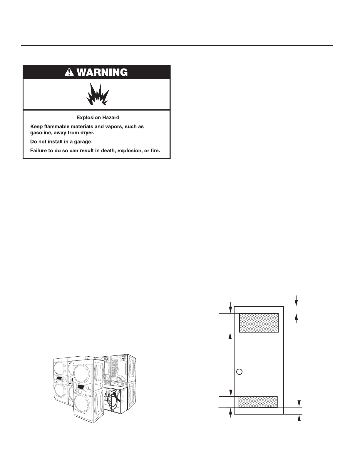
Recessed Area and Closet Installation Instructions
This washer/dryer may be installed in a recessed area or closet.
For recessed area and closet installations, minimum clearances
can be found on the warning label on the rear of the dryer or in
“Dimensions/Clearances.”
The installation spacing is in inches and is the minimum
allowable. Additional spacing should be considered for ease
of installation, servicing, and compliance with local codes and
ordinances.
If closet door is installed, the minimum unobstructed air
opening in the top and bottom is required. Louvered doors
with equivalent air openings are acceptable.
The dryer must be exhausted outdoors.
2
48 in.
(310 cm2)
Front
View
Closet
door
3"
(76 mm)
3"
2
24 in.
(155 cm2)
(76 mm)
8
Page 9
STACKED WASHER/GAS DRYER INSTALLATION
Stacked Washer/Gas Dryer Electrical Requirements
IMPORTANT: The washer/dryer must be electrically grounded
in accordance with local codes and ordinances or, in the
absence of local codes, with the National Electrical Code,
ANSI/NFPA 70, latest edition, or Canadian Electrical Code, CSA
C22.1. If codes permit and a separate ground wire is used, it is
recommended that a qualied electrical installer determine
that the ground path is adequate.
A copy of the above code standards can be obtained from:
National Fire Protection Association
One Batterymarch Park, Quincy, MA 02269
n
Do not ground to a gas pipe.
n Do not have a fuse in the neutral or ground circuit.
n A 120 volt, 60 Hz, AC only, 15- or 20-amp, fused electrical
circuit is required. A time-delay fuse or circuit breaker is also
recommended. It is recommended that a separate circuit
serving only this washer/dryer be provided.
n
This washer/dryer is equipped with a power supply cord
having a 3-prong grounding plug.
n
To minimize the possibility of shock, the cord must be
plugged into a mating, 3 prong, grounding-type outlet,
grounded in accordance with local codes and ordinances.
If a mating outlet is not available, it is the personal
responsibility and obligation of the customer to have the
properly grounded outlet installed by a qualied electrician.
n
If codes permit and a separate ground wire is used, it is
recommended that a qualied electrician determine that the
ground path is adequate.
n
Check with a qualied electrician if you are not sure the
washer/dryer is properly grounded.
CSA International
8501 East Pleasant Valley Road
Cleveland, Ohio 44131-5575
REQUIREMENTS
Stacked Washer/Gas Dryer Grounding
9
Page 10
STACKED WASHER/GAS DRYER INSTALLATION
REQUIREMENTS
Stacked Washer/Gas Dryer Gas Supply
IMPORTANT: Observe all governing codes and ordinances.
This installation must conform with all local codes and
ordinances. In the absence of local codes, installation must
conform with American National Standard, National Fuel Gas
Code ANSI Z223.1/NFPA 54 or CAN/CSA B149.
A copy of the above code standards can be obtained from:
National Fire Protection Association
One Batterymarch Park, Quincy, MA 02269
The design of this washer/dryer has been certied by CSA
International for use at altitudes up to 10,000 feet (3048 m)
above sea level at the B.T.U. rating indicated on the model/
serial plate. Burner input adjustments are not required when
the washer/dryer is operated up to this elevation.
When installed above 10,000 feet (3048 m), a four percent
(4%) reduction of the burner B.T.U. rating shown on the model/
serial plate is required for each 1,000 foot (305 m) increase in
elevation. For assistance when converting to other gas types
and/or installing above 10,000 feet (3048 m) elevation, contact
your local service company.
CSA International
8501 East Pleasant Valley Road
Cleveland, Ohio 44131-5575
10
Page 11
STACKED WASHER/ELECTRIC DRYER INSTALLATION
REQUIREMENTS
Stacked Washer/Electric Dryer Location
Stacked washer/electric dryer installation clearances
n The location must be large enough to allow the washer and
dryer doors to be fully opened.
n
Additional spacing should be considered for ease of
installation and servicing. The doors open more than 180°.
The washer door is not reversible.
n
Additional clearances might be required for wall, door, and
oor moldings.
n
Additional spacing of 1" (25 mm) on all sides of the washer/
dryer is recommended to reduce noise transfer.
Companion appliance spacing should also be considered.
n
Recessed Area and Closet Installation Instructions
This washer/dryer may be installed in a recessed area or closet.
For recessed area and closet installations, minimum clearances
Selecting the proper location for your washer/dryer improves
performance and minimizes noise and possible washer “walk.”
Your washer/dryer can be installed in a basement, laundry room,
or recessed area. See “Drain System.”
Companion appliance location requirements should also be
considered.
IMPORTANT: Do not install or store the washer/dryer where
it will be exposed to the weather. Do not store or operate the
washer/dryer in temperatures at or below 32°F (0°C). Some
water can remain in the washer and can cause damage in low
temperatures. Proper installation is your responsibility.
You will need:
n A water heater set to deliver 120°F (49°C) water to the
washer.
n
A grounded electrical outlet located within 6 ft. (1.8 m) of
where the power cord is attached to the back of the washer.
See “Electrical Requirements.”
n
Hot and cold water faucets located within 4 ft. (1.2 m)
of the hot and cold water ll valves, and water pressure
of 20–100 psi (137.9–689.6 kPa).
n
A level oor with a maximum slope of 1" (25 mm) under
entire washer/dryer. Installing the washer/dryer on soft oor
surfaces, such as carpets or surfaces with foam backing,
is not recommended.
n
A sturdy and solid oor to support the washer/dryer with
a total weight (water and load) of 450 lbs (204 kg).
n
A oor drain under the bulkhead. Prefabricated bulkheads
with electrical outlets, water inlet lines, and drain facilities
should be used only where local codes permit.
can be found on the warning label on the rear of the dryer.
The installation spacing is in inches and is the minimum
allowable. Additional spacing should be considered for ease
of installation, servicing, and compliance with local codes and
ordinances.
If closet door is installed, the minimum unobstructed air
opening in the top and bottom is required. Louvered doors
with equivalent air openings are acceptable.
The dryer must be exhausted outdoors.
2
48 in.
(310 cm2)
Front
View
2
24 in.
(155 cm2)
Closet
door
3"
(76 mm)
3"
(76 mm)
11
Page 12
STACKED WASHER/ELECTRIC DRYER INSTALLATION
REQUIREMENTS
Stacked Washer/Electric Dryer Electrical
Requirements
Stacked Washer/Electric Dryer GroundingWasher Electrical Requirements
n Do not have a fuse in the neutral or ground circuit.
n This washer/dryer is equipped with a power supply cord
having a 3 prong grounding plug.
n
To minimize the possibility of shock, the cord must be
plugged into a mating, 3 prong, grounding-type outlet,
grounded in accordance with local codes and ordinances.
If a mating outlet is not available, it is the personal
responsibility and obligation of the customer to have the
properly grounded outlet installed by a qualied electrician.
n
If codes permit and a separate ground wire is used, it is
recommended that a qualied electrician determine that
the ground path is adequate.
n
Check with a qualied electrician if you are not sure the
washer is properly grounded.
12
Page 13

STACKED WASHER/ELECTRIC DRYER INSTALLATION
REQUIREMENTS
Dryer Electrical Requirements
It is your responsibility:
n To contact a qualied electrical installer.
n To be sure that the electrical connection is adequate and in
conformance with the National Electrical Code, ANSI/NFPA
70-latest edition and all local codes and ordinances.
The National Electrical Code requires a 4-wire power supply
connection for homes built after 1996, dryer circuits involved
in remodeling after 1996, and all mobile home installations.
A copy of the above code standards can be obtained from:
National Fire Protection Association, One Batterymarch
Park, Quincy, MA 02269.
n
To supply the required 3 or 4 wire, single phase, 240 volt, 60
Hz., AC only electrical supply (or 3 or 4 wire, 120/208 volt
electrical supply, if specied on the serial/rating plate) on a
separate 30-amp circuit, fused on both sides of the line. A
time delay fuse or circuit breaker is recommended. Connect
to an individual branch circuit. Do not have a fuse in the
neutral or grounding circuit.
n
Do not use an extension cord.
n If codes permit and a separate ground wire is used, it is
recommended that a qualied electrician determine that the
ground path is adequate.
Electric Dryer Power Supply Cord
Electrical Connection
To properly install your dryer, you must determine the type
of electrical connection you will be using and follow the
instructions provided for it here.
n
This dryer is manufactured ready to install with a 3-wire
electrical supply connection. The neutral ground conductor
is permanently connected to the neutral conductor (white
wire) within the dryer. If the dryer is installed with a 4-wire
electrical supply connection, the neutral ground conductor
must be removed from the external ground connector (green
screw), and secured under the neutral terminal (center or
white wire) of the terminal block. When the neutral ground
conductor is secured under the neutral terminal (center
or white wire) of the terminal block, the dryer cabinet is
isolated from the neutral conductor.
n
If local codes do not permit the connection of a neutral
ground wire to the neutral wire, see “Optional 3-wire
connection” section.
n
A 4-wire power supply connection must be
used when the appliance is installed in a location where
grounding through the neutral conductor is prohibited.
Grounding through the neutral is prohibited for (1)
new branch-circuit installations, (2) mobile homes, (3)
recreational vehicles, and (4) areas where local codes
prohibit grounding through the neutral conductor.
If using a power supply cord:
Use a UL listed power supply cord kit marked for use with
clothes dryers. The kit should contain:
n
A UL listed 30-amp power supply cord, rated 240 volt
minimum. The cord should be type SRD or SRDT and be at
least 4 ft. (1.22 m) long. The wires that connect to the dryer
must end in ring terminals or “U” shaped spade terminals
with upturned ends.
A UL listed strain relief.
n
If your outlet looks like this:
Then choose a 4-wire power supply cord with ring
or spade terminals and UL listed strain relief. The
4-wire power supply cord, at least 4 ft. (1.22 m)
long, must have four 10-gauge copper wires and
match a 4-wire receptacle of NEMA Type 14-30R.
4-wire
receptacle
(14-30R)
The ground wire (ground conductor) may be either
green or bare. The neutral conductor must be
identied by a white cover.
If your outlet looks like this:
Then choose a 3-wire power supply cord with ring
or spade terminals and UL listed strain relief. The
3-wire power supply cord, at least 4 ft. (1.22 m)
long, must have three 10-gauge copper wires and
match a 3-wire receptacle of NEMA Type 10-30R.
3-wire
receptacle
(10-30R)
13
Page 14

STACKED WASHER/ELECTRIC DRYER INSTALLATION
REQUIREMENTS
Dryer Direct Wire
If connecting by direct wire:
Power supply cable must match power supply (4-wire or 3-wire)
and be:
n
Flexible armored cable or nonmetallic sheathed copper
cable (with ground wire), covered with exible metallic
conduit. All current-carrying wires must be insulated.
n
10-gauge solid copper wire (do not use aluminum).
n At least 5 ft. (1.52 m) long.
14
Page 15

DRYER VENTING REQUIREMENTS
Elbows:
■ 45° elbows provide better airow than 90° elbows.
WARNING: To reduce the risk of re, this dryer MUST BE
EXHAUSTED OUTDOORS.
IMPORTANT: Observe all governing codes and ordinances.
Dryer exhaust must not be connected into any gas vent,
chimney, wall, ceiling, attic, crawlspace, or a concealed space
of a building. Only rigid or exible metal vent shall be used for
exhausting.
4"
(102 mm)
Good
Better
Clamps:
■ Use clamps to seal all joints.
■ Exhaust vent must not be connected or secured with
screws or other fastening devices that extend into interior
of duct and catch lint. Do not use duct tape.
4" (102 mm) heavy, metal exhaust vent
■ Only a 4" (102 mm) heavy, metal exhaust vent and clamps
may be used.
■ Do not use plastic or metal foil vent.
Rigid metal vent:
■ Recommended for best drying performance and to avoid
crushing and kinking.
Flexible metal vent: (Acceptable only if accessible to
clean)
■ Must be fully extended and supported in nal dryer location.
■ Remove excess to avoid sagging and kinking that may
result in reduced airow and poor performance.
■ Do not install in enclosed walls, ceilings, or oors.
■ The total length should not exceed 7
NOTE: If using an existing vent system, clean lint from entire
length of the system and make sure exhaust hood is not
plugged with lint. Replace plastic or metal foil vents with rigid
metal or exible metal vents. Review “Vent System Chart” and
if necessary, modify existing vent system to achieve best drying
performance.
3
⁄4 ft. (2.4 m).
15
Page 16

DRYER VENTING REQUIREMENTS
Vent Hoods
4" (102 mm) Diameter Exhaust Hoods
box hood louvered hood angled hood
Vent System Length
Maximum Vent Length/Vent Connection
Exhaust hood must be at least 12" (305 mm) from the ground
or any object that may be in the path of the exhaust (such as
owers, rocks, bushes, or snow).
12" min.
(305 mm)
Maximum length of vent system depends upon the type of vent
used, number of elbows, and type of exhaust hood.
Vent System Chart (Rigid Metal Vent)
No. of Box and Angled
90˚ Turns Louvered Hood Hood
0 135 ft. (41.2 m) 129 ft. (39.3 m)
1 125 ft. (38.1 m) 119 ft. (36.3 m)
2 115 ft. (35.1 m) 109 ft. (33.2 m)
3 106 ft. (32.3 m) 100 ft. (30.5 m)
4 98 ft. (29.9 m) 92 ft. (28.0 m)
For vent systems not covered by the vent specication chart,
see your parts distributor.
Provision must be made for enough air for combustion and
ventilation. (Check governing codes and ordinances.) See
“Recessed Area and Closet Installation Instructions” in the
“Stacked Washer/Gas Dryer Location” and “Stacked Washer/
Electric Dryer Location” sections.
A 4" (102 mm) outlet hood is preferred. However, a 2
(64 mm) outlet exhaust hood may be used. A 2
outlet creates greater back pressure than other hood types.
For permanent installation, a stationary vent system is required.
1
⁄2"
1
⁄2" (64 mm)
Connect Vent
1. If connecting to existing vent, make sure the vent is clean.
3. Tighten hose clamp with Phillips screwdriver.
4. Make sure the vent is secured to exhaust hood with
a 4" (102 mm) clamp.
5.
Move dryer into nal position. Do not crush or kink vent.
Make sure dryer is level.
2. Using a 4" (102 mm) clamp, connect vent to exhaust outlet
in dryer.
NOTE: Do not remove vent collar.
Vent collar
16
Page 17

DRYER VENTING REQUIREMENTS
If an Exhaust Hood Cannot be Used
The outside end of main vent should have a sweep elbow
directed downward.
12" min.
(305 mm)*
* Minimum clearance above
any accumulation of snow,
ice, or debris such as leaves
If main vent travels vertically through the roof, rather than
through wall, install a 180° sweep elbow on end of vent at least
2 ft. (610 mm) above surface of roof.
The opening in wall or roof shall have a diameter 1⁄2" (13 mm)
larger than vent diameter. Vent should be centered in opening.
Do not install screening over end of vent for best performance.
24" min.
(610 mm)
Multiple Dryer Venting
A main vent can be used for venting a group of dryers. The
main vent should be sized to remove 200 CFM of air per dryer.
Large-capacity lint screens of proper design may be used in
main vent if checked and cleaned frequently. The room where
the dryers are located should have make-up air equal to or
greater than CFM of all the dryers in the room.
Each vent should enter the main vent at an angle pointing in
the direction of the airow. Vents entering from the opposite
side should be staggered to reduce the exhausted air from
interfering with the other vents.
Back-draft Damper Kit, Part No. 3391910, is available from
your distributor and should be installed in the vent of each
dryer to keep exhausted air from returning into dryers and to
keep exhaust in balance within main vent. Unobstructed return
air openings are required.
30˚ max.
air ow
The maximum angle of each vent entering the main vent should
be no more than 30°.
17
Page 18

DRYER GAS SUPPLY REQUIREMENTS
Type of Gas
This dryer is equipped for use with natural gas. It is designcertied by CSA International for LP (propane and butane)
gases with appropriate conversion. No attempt shall be made
to convert dryer from gas specied on serial/rating plate for use
with a different gas without consulting the serving gas supplier.
Conversion must be done by a qualied service technician.
Gas conversion kit part numbers are listed on gas valve burner
base.
Gas Supply Line
Recommended Method
Flexible Metal Appliance Connector
Provide a gas supply line of 1⁄2" (13 mm) rigid (IPS) pipe to
dryer location. Pipe joint compounds that resist action of LP
gas must be used. Do not use TEFLON
piping or tubing size can be 1⁄2" (13 mm) minimum. Usually, LP
gas suppliers determine size and materials used in the system.
®†
tape. With LP gas,
Gas Supply Pressure Testing
A 1/8" (3 mm) NPT minimum plugged tapping, accessible for
gauge testing, must be installed immediately downstream of
the installed shut-off valve to the dryer (as shown above). The
dryer must be disconnected from the gas supply piping system
during any pressure testing of the system at test pressures in
excess of 1/2" psig (352 kg/m
2
).
Alternate Method
It is recommended that a new exible stainless steel gas line,
design-certied by CSA International, be used for connecting
the dryer to the gas supply line. (The gas pipe which extends
through the lower rear of the dryer is provided with 3⁄8"
(10 mm) male pipe thread.)
NOTE: Do not kink or damage the exible stainless steel gas
line when moving the door.
Rigid Pipe Connection
The rigid pipe connection requires a combination of pipe ttings
to obtain an in-line connection to dryer.
The gas supply may also be connected using 3⁄ 8" (10 mm)
approved copper or aluminum tubing. If the total length of
the supply line is more than 20 ft. (6.1 m), larger tubing will
be required.
If using natural gas, do not use copper tubing. Pipe joint
compounds that resist action of type of gas supplied must
be used.
Shut-off valve required
The supply line must be equipped with a manual shut-off
valve installed within 6 ft. (1.8 m) of dryer in accordance
with National Fuel Gas Code, ANSI Z223.1. This valve should
be located in same room as dryer. It should be in a location
that allows ease of opening and closing. Do not block access
to shut-off valve. In Canada, an individual manual shut-off
valve must be installed in accordance with the B149 installation
codes CAN/CGA B149.1 and CAN/CGA B149.2.
18
†®TEFLON is a registered trademark of E.I. Du Pont De Nemours and Company.
Page 19

INSTALLING STACKED WASHER/DRYER
Remove Transport System
NOTE: Slide washer/dryer onto cardboard or hardboard before
moving to avoid damaging oor covering.
IMPORTANT: Position the washer/dryer so that the rear of
the washer is within approximately 3 ft. (900 mm) of its nal
location.
There are 4 shipping bolts in the rear panel of the washer that
support the suspension system during transportation. These
bolts also retain the power cord inside the washer until the
bolts are removed.
1.
Keep the washer/dryer in the upright position while removing
the shipping bolts.
2.
Using a 1/2" (13 mm) wrench, loosen each of the bolts.
4. Models with separate washer power cords: Push the power
cord plug into the opening on the right side of the rear panel
and pull the power cord through the opening on the left side
of the rear panel and close holes with the attached cap. Do
not pull plug end of power cord through the right side hole.
NOTE: To avoid damage to internal washer parts or the
power cord, if the cord does not pull out of the washer rear
panel easily, do not force it. Remove the washer rear panel
and guide the power cord around the obstruction and out
the hole on the left side of the rear panel.
3. Once the bolt is loose, move it to the center of the hole
and completely pull out the bolt, including the plastic spacer
covering the bolt. Once all 4 bolts are removed, discard the
bolts and spacers.
5.
Close the bolt holes with the 4 transport bolt hole plugs.
IMPORTANT: If the washer/dryer is to be transported, call
your product distributor or installer. To avoid suspension and
structural damage, your washer/dryer must be properly set up
for relocation by a trained professional.
19
Page 20

INSTALLING STACKED WASHER/DRYER
Connect Inlet Hoses
Insert new hose washers (supplied) into each end of the inlet
hoses. Firmly seat the washers in the couplings.
Connect Inlet Hoses to Washer
1. Attach the cold water hose to the washer’s cold water inlet
valve. Screw on coupling by hand until it is seated on the
washer.
washer
coupling
Connect Inlet Hoses to Water Faucets
Make sure the washer drum is empty.
1. Attach a hose to the hot water faucet. Screw on coupling
by hand until it is seated on the washer.
2. Attach a hose to the cold water faucet. Screw on coupling
by hand until it is seated on the washer.
3.
Using pliers, tighten the couplings with an additional
two-thirds turn.
2. Attach the hot water hose to the washer’s hot water inlet
valve. Screw on coupling by hand until it is seated on the
washer.
3. Using pliers, tighten the couplings with an additional
two-thirds turn.
NOTE: Do not overtighten. Damage to the valve can result.
4. Turn on the water faucets completely and check for leaks.
NOTE: Do not overtighten or use tape or sealants on the valve.
Damage to the valves can result.
Clear Water Lines
n Run water through both faucets and inlet hoses, into a
laundry tub, drainpipe, or bucket, to get rid of particles
in the water lines that might clog the inlet valve screens.
n
Check the temperature of the water to make sure that the
hot water hose is connected to the hot water faucet and that
the cold water hose is connected to the cold water faucet.
20
NOTE: Replace inlet hoses after 5 years of use to reduce the
risk of hose failure. Record hose installation or replacement
dates on the hoses for future reference.
Periodically inspect and replace hoses if bulges, kinks, cuts,
wear, or leaks are found.
Page 21

INSTALLING STACKED WASHER/DRYER
Route Drain Hose
Proper routing of the drain hose avoids damage to your oor
due to water leakage. Read and follow these instructions.
Remove drain hose from the washer drum
1. Using locking pliers, squeeze hose clamp tabs together and
insert over the end of the drain hose.
2. Slide the drain hose onto the washer connection.
3. Once the drain hose is in place, release the pliers.
4. The washer drain system can be installed using a oor drain,
wall standpipe, oor standpipe, or laundry tub.
Laundry tub drain or standpipe drain
Connect the drain hose form to the corrugated drain hose.
Snap either end of the drain hose form to the
drain hose at the point where the corrugation
begins.
Secure Drain Hose
1. Drape the power cord over the washer top.
2. Move the washer to its nal location.
3. Place the drain hose
in the laundry tub or
standpipe as shown.
4. Secure the drain hose using
the supplied beaded tie
strap.
41/2"
(114 mm)
41/2"
(114 mm)
Bend drain hose over drain hose form and
snap into place.
NOTE: Hose must not extend more than 1"
(25 mm) past the end of the U bend.
To keep drain water from going back into the washer:
n Do not straighten the drain hose, do not force excess drain
hose into standpipe. Hose should be secure, but loose
enough to provide a gap for air.
n
Do not lay excess hose on the bottom of the laundry tub.
Floor drain
You may need additional parts. See “Alternate Parts.”
5. If the washer faucets and the
drain standpipe are recessed, put
the hooked end of the drain hose
in the standpipe as shown.
NOTES:
n
Do not force excess drain hose
back into the rear of the washer.
n
To avoid siphoning, do not
seal the drain hose into the
standpipe.
21
Page 22

WASHER DRAIN SYSTEM
The washer can be installed using the standpipe drain system
(oor or wall), the laundry tub drain system, or the oor drain
system.
Standpipe drain system – wall or oor
The standpipe drain requires a minimum diameter standpipe of
2" (50 mm). The minimum carry-away capacity can be no less
than 10 gal. (38 L) per minute
.
Wall
The top of the standpipe must be at least 30" (762 mm) high
and no higher than 96" (2.4 m) from the bottom of the washer.
Floor
Laundry tub drain system
The laundry tub needs a minimum 20 gal. (76 L) capacity.
The top of the laundry tub must be at least 30" (762 mm)
above the oor.
30
"
(762 mm)
Floor drain system
The oor drain system requires a siphon break that may be
purchased separately.
The siphon break (Part Number 285834) must be a minimum of
28" (710 mm) from the bottom of the washer. Additional hoses
might be needed.
30
" min.
(762 mm)
Syphonbreak
28
"
(710 mm)
22
Page 23

ELECTRIC DRYER ELECTRICAL CONNECTIONS
Strain Relief
Remove Terminal Block Cover
Power Supply Cord Strain Relief
1. Insert strain relief.
2. Insert power cord into strain relief.
Strain Relief
Direct Wire Strain Relief
1. Insert strain relief. 2. Insert conduit into strain relief and tighten clamp.
23
Page 24

ELECTRIC DRYER ELECTRICAL CONNECTIONS
Connection Options
Power Cord
Direct Wire
4-wire receptacle (NEMA Type 14-30R)
3-wire receptacle (NEMA Type 10-30R)
4-wire direct
3-wire direct
Connecting 4-Wire Connection: Power Supply Cord
IMPORTANT: A 4-wire connection is required for mobile
homes and where local codes do not permit the use of 3-wire
connections.
1"
(25 mm)
5"
(127 mm)
3"
(89 mm)
Standard Power Supply Cord Connectors
Flanged spade connector Ring Connector
Connecting Ground and Neutral Wires
1. Remove center terminal block screw and the ground wire
by removing the external ground connector screw.
Connect ground and neutral wire to center terminal block.
2.
Connecting Direct Wire Ground
3. Connect ground wire (green or bare) with external ground
connector screw.
Connecting Remaining Wires
4. Connect remaining wires with outer terminal block screws.
24
Page 25

ELECTRIC DRYER ELECTRICAL CONNECTIONS
Connecting 3-Wire Connection: Power Supply Cord
Standard Power Cord Connectors
Flanged spade connector Ring Connector
Connecting Neutral Wire
1. Loosen or remove center terminal block screw.
2. Connect neutral wire to center terminal block.
3. Connect remaining wires with outer terminal block screws.
Connecting 4-Wire Connection: Direct Wire
IMPORTANT: A 4-wire connection is required for mobile
homes and where local codes do not permit the use of 3-wire
connections.
Direct wire cable must have 5 ft. (1.52 m) of extra length so
dryer can be moved if needed.
Strip 5" (127 mm) of outer covering from end of cable,
leaving bare ground wire at 5" (127 mm). Cut 1
3 remaining wires. Strip insulation back 1" (25 mm). Shape
ends of wires into a hook shape.
1
⁄2" (38 mm) from
Connecting Ground and Neutral Wires
1. Remove center terminal block screw and the ground wire
by removing the external ground connector screw.
25
Page 26

ELECTRIC DRYER ELECTRICAL CONNECTIONS
Connecting 4-Wire Connection: Direct Wire
Connecting Ground and Neutral Wires (cont.)
Connecting Remaining Wires
2. Connect ground and neutral wire to center terminal block.
Connecting Direct Wire Ground
3. Connect ground wire (green or bare) with external ground
connector screw.
4. Connect remaining wires to outer terminal block.
Connecting 3-Wire Connection: Direct Wire
Use where local codes permit connecting
cabinet-ground conductor to neutral wire.
Direct wire cable must have 5 ft. (1.52 m) of extra length so
dryer can be moved if needed.
1
Strip 3
⁄2" (89 mm) of outer covering from end of cable. Strip
insulation back 1" (25 mm). If using 3-wire cable with ground
wire, cut bare wire even with outer covering. Shape ends of
wires into a hook shape.
Connecting Neutral Wire
1. Loosen or remove center terminal block screw.
2. Connect neutral wire to center terminal block.
3. Connect remaining wires to outer terminal block.
26
Page 27

ELECTRIC DRYER ELECTRICAL CONNECTIONS
Connecting 3-Wire Connection: Optional
Use for direct wire or power supply cord where local codes
do not permit connecting cabinet-ground conductor to
neutral wire.
Connecting Neutral Wire
1. Remove center terminal block screw. Also remove neutral
ground wire by removing external ground conductor screw.
2.
Connect neutral wire and neutral wire of power supply cord/
cable to center terminal block.
3. Connect remaining wires to outer terminal block.
4. Connect a separate copper ground wire from the external
ground conductor to an adequate ground.
Leveling Stacked Washer/Dryer
Leveling your washer/dryer properly reduces excess noise and
vibration.
1. Remove cardboard from beneath washer/dryer. Place a level
on top edges of washer/dryer, checking each side and front.
If not level, tip washer/dryer and adjust feet up or down as
shown in Steps 3 and 4, repeating as necessary.
LEVELING
Not Level LEVEL Not Level
27
Page 28

LEVELING
Leveling Stacked Washer/Dryer (cont.)
2. Grip washer/dryer from top and rock back and forth,
making sure all four feet are rmly on oor. Repeat, rocking
washer/dryer from side to side. If washer/dryer rocks, go
to Step 3 and adjust leveling feet. If all four feet are in rm
contact with oor, go to Step 4.
3. If washer/dryer is not level, use a 9/16" or 14 mm openend
or adjustable wrench to turn jam nuts clockwise (as viewed
from above) on feet until they are about 1/2" (13 mm)
from the washer/dryer cabinet. Then turn the leveling foot
counterclockwise to lower
the washer/dryer or clockwise
Complete Installation
1. Check the electrical requirements. Be sure that you have the
correct electrical supply and the recommended grounding
method. See “Electrical Requirements.”
2. Check that all parts are now installed. If there is an extra part,
go back through the steps.
3. Check that you have all of your tools.
4. Dispose of/recycle all packaging materials.
5. Check that the water faucets are on.
6. Check for leaks around faucets and inlet hoses.
to raise the washer/dryer. Recheck levelness of washer/dryer
and that all four feet are rmly in contact with the oor. Repeat
as needed.
HELPFUL TIP: You may want to prop up front of washer/
dryer about 4" (102 mm) with a wood block or similar object
that will support weight of washer/dryer.
Jam nut
4. When washer/dryer is level and all four feet are rmly
in contact with the oor, use a 9/16" or 14 mm open-end
or adjustable wrench to turn jam nuts counterclockwise
(as viewed from above) on leveling feet tightly against
washer/dryer cabinet.
HELPFUL TIP: You may want to prop washer/dryer with
wooden block.
8. To test and to clean your washer, measure 1/2 the detergent
manufacturer’s recommended amount of High Efciency (HE)
detergent for a medium-size load. Pour the detergent into the
detergent dispenser. Select any cycle and allow the washer
to complete one whole cycle.
9. Check dryer operation. Using a full heat cycle, let the dryer
run for at least ve minutes. Dryer will stop when time is
used up.
NOTE: Dryer door must be closed for dryer to operate. When
door is open, dryer stops, but timer continues to run. To restart
dryer, close door and push cycle button.
If the burner does not ignite and you can feel no heat inside
the dryer, shut off dryer for ve minutes. Check that all supply
valve controls are in “ON” position and that the electrical cord
is plugged in. Repeat ve-minute test.
7. Plug into a grounded outlet, or connect power.
28
Page 29

REVERSING DRYER DOOR SWING
NOTE: Dryer only. Washer door is not reversible.
Remove the Door Assembly
1. Place a towel or soft cloth on top of dryer or work space to
avoid scratching of the surface.
2.
Remove 3 of the 4 screws that hold the door hinge on the
front panel of the dryer. Partially loosen the remaining screw
with keyhole opening and lift the door off the screw.
4. Lift the inner door assembly off outer door assembly.
5. Rotate outer door 180°.
Lay the door assembly on a previously prepared at surface
3.
with the inside (inner door assembly) facing up, and remove
6 phillips-head screws to release outer door assembly from
inner door assembly.
NOTE: It is important that you remove only 6 indicated screws.
Reverse Hinge
1. Use a small at-blade screwdriver to remove 2 plug strips
from the inner door. Slide the head of the screwdriver under
the plugs, without scratching inner door surface, and lift up
strip.
2. Remove the 4 screws that attach to inner door hinge.
29
Page 30

REVERSING DRYER DOOR SWING
3. Move hinge to other side. Reinstall 4 screws.
4. Reinstall plug strips on opposite side of the inner door.
Reverse the strike
1. Use a small at-blade screwdriver to remove plug strip from
the dryer door opening. Slide the head of the screwdriver
under the plugs, without scratching dryer surface, and lift
up strip.
2.
Remove the strike using a Phillips screwdriver.
5. Check for ngerprints on the glass. Clean if necessary.
Replace the Door Assembly
1. Place the inner door assembly inside the outer door
assembly.
Reassemble the inner and outer door assemblies with the
2.
6 screws.
3. Insert strike on the opposite side.
Reinstall the door
1. Partially insert the third screw from the top; then slide the
hinge onto this screw while hooking the hinge into the front
panel hole. Reattach door to dryer front panel with the
remaining three screws.
30
2.
Check for ngerprints on the glass. Clean if necessary.
3. Close door and check that it latches securely.
Page 31

STACKED WASHER/DRYER MAINTENANCE INSTRUCTIONS
Washer
Cleaning the Door Seal/Bellow
To clean washer interior:
1. Open the washer door and remove any clothing or items
from the washer.
2. Inspect inner glass door. If debris is present, wipe it off using
a damp cloth.
3. Inspect the colored seal/bellow between the door opening
and the basket for stained areas. Pull back the seal/bellow
to inspect all areas under the seal/bellow and to check for
foreign objects.
Seal/bellow
4. If stained areas are found, wipe down these areas of the
seal/bellow:
a)
Mix a dilute solution, using 3/4 cup (177 mL) of liquid
chlorine bleach, and 1 gal. (3.8 L) of warm tap water.
b) Wipe the seal/bellow area with the dilute solution, using
a damp cloth.
c) Let stand 5 minutes.
d)
Wipe down area thoroughly with a dry cloth and let the
washer interior air dry with door open.
IMPORTANT:
1. Open the washer door and remove any clothing or items
from the washer.
2. Use liquid chlorine bleach:
Open the dispenser drawer and immediately add 2/3
cup (160 mL) of liquid chlorine bleach to the bleach
compartment.
NOTE: Do not add any detergent. Use of more than 2/3 cup
(160 mL) of bleach will cause product damage over time.
3. Close the washer door and the dispenser drawer.
4. To start the Washer Cleanout cycle, rst enter “Service
Mode.” Then press and hold the lower-right (QUICK CYCLE)
button for 2 seconds. With the entire display ashing, press
the center-right (BRIGHTS) button.
To exit out of the service mode and activate the clean wash
cycle, push the BRIGHTS button, then turn the key.
NOTE: The door will lock, the basket will rotate 1/2 turn,
then the door will unlock and lock again, then the Washer
Cleanout Cycle will continue.
n
The washer will not ll, but the basket will rotate while
the washer runs a short sensing cycle. This will take
approximately 3 minutes.
5. The cycle will determine whether clothing or other items are
in the washer.
a) If no items are detected in the washer, it will proceed to
Step 7.
b) If any items are detected in the washer, “F-34” will be
displayed. Then the door will unlock.
n
Wear rubber gloves when cleaning for prolonged periods.
n Refer to the bleach manufacturer’s instructions for proper
use.
Maintenance Instructions:
This washer has a special cycle that uses higher water volumes
in combination with liquid chlorine bleach to thoroughly clean
the inside of the washer.
NOTES:
n
Read these instructions completely before beginning the
cleaning process.
n
If necessary, the cleaning cycle may be interrupted by
pressing the lower-right (QUICK CYCLE) button twice.
However, this will not immediately stop the cycle. The
washer will continue with several rinse and drain steps to
ensure that all remaining bleach is rinsed from the washer.
n
Enter the service mode and then press and hold the
lower-right (QUICK CYCLE) button to cancel the failure
code.
Then repeat steps 1, 3, and 4 to start the cycle again.
6. Once the cycle has begun, allow the cycle to complete.
7. After the cycle is complete, leave the door open slightly to
allow for better ventilation and drying of washer interior.
31
Page 32

STACKED WASHER/DRYER MAINTENANCE INSTRUCTIONS
Washer
Always do the following to maintain washer
freshness:
n Use only HE High Efciency detergent.
n Leave the door slightly open after each cycle to allow for
better ventilation and drying of washer interior.
n Clean the washer monthly using the Washer Maintenance
Procedure, using 2/3 cup (160 mL) of liquid chlorine bleach.
n If the procedure does not sufciently improve the washer
freshness, please evaluate your installation and usage
conditions for other causes.
Cleaning the exterior
Use a soft damp cloth or sponge to wipe up any spills.
Occasionally wipe the outside of your washer to keep it looking
new. Use mild soap and water. Do not use abrasive products.
Cleaning the dispenser drawer
The dispenser drawer is removable for easy cleaning.
1. Unlock the dispenser drawer for removal by inserting
a at-blade screwdriver into the catch release. Remove
the dispenser drawer.
2. Remove the inserts (the siphon from the softener and bleach
compartments).
3. Wash the parts under running water.
NOTE: Do not wash components in the dishwasher.
4. Replace the inserts and return the dispenser to the drawer.
Water inlet hoses
Dryer
Maintenance instructions:
• Clean lint screen before and after each cycle.
• Removing accumulated lint:
From inside the dryer cabinet:
Lint should be removed every 2
years or more often, depending
on dryer usage. Cleaning should
be done by a qualied person.
From the exhaust vent:
Lint should be removed every 2
years, or more often, depending
on dryer usage.
• Keep area around dryer clear and free from combustible
materials, gasoline and other ammable vapors and liquids.
• Keep dryer area clear and free from items that would
obstruct the ow of combustion and ventilation air.
If dryer does not operate, check the following:
• Electrical supply is connected.
• Circuit breaker is not tripped or house fuse is
not blown.
• Door is closed. Listen closely to hear the door switch
activate.
• Cycle selection button has been pushed rmly.
• For gas dryers, check that gas supply shut-off
valves are set in open position.
Replace the inlet hoses after 5 years of use to reduce the risk
of hose failure. Periodically inspect and replace inlet hoses if
bulges, kinks, cuts, wear, or leaks are found.
When replacing your inlet hoses, record the date of
replacement.
IF YOU NEED ASSISTANCE
Contact your authorized Maytag® Commercial Laundry distributor. To locate your authorized Maytag® Commercial Laundry
distributor, or for web inquiries, visit www.MaytagCommercialLaundry.com.
If you cannot locate your distributor, the Commercial Laundry Support Center will answer any questions about operating or
maintaining your washer/dryer not covered in the “Installation Instructions.”
Just dial 1-800 NO BELTS (1-800-662-3587) — the call is toll free.
When you call, you will need the washer/dryer model numbers and serial numbers. Both numbers can be found on the serial-rating
plate located in the dryer door well.
32
Page 33

ELECTRONIC CONTROL SETUP INSTRUCTIONS
WHITES
PERM.
PRESS
COLORS
DELICATES
AND KNITS
BRIGHTS
QUICK
CYCLE
WASHER
Washer control
NOTE: After the washer/dryer has been installed and plugged
in, the display will show “0 MINUTES” on the washer and dryer
portions of the display. After the washer and dryer doors have
been opened and closed, the display will show the price for
each machine. On washer/dryers set for free cycles, the display
sections will ash “SELECT CYCLE.”
1.
PD Models: Insert coins until “SELECT CYCLE” ashes on
the display portion of the washer or dryer that is to be run.
PR Models: A debit card is required rather than coins.
Generation 1 or 2 debit card systems may be used; but
when the Generation 2 debit system is used, the controls
will automatically be set to Enhanced Debit mode (J. Ed).
In Enhanced Debit mode, the card balance will also display
when a debit card is inserted into the reader.
2.
Door must be closed on the desired washer/dryer before
cycle selection is made.
3.
Press the fabric setting button for the washer/dryer cycle
desired. After the cycle is started, the time will display and
count down.
DRYER
WHITES
& COLORS
PERM.
PRESS
Dryer control
DELICATES
General Washer/Dryer User Information
SCROLLING “OUT OF ORDER” MESSAGE, FOLLOWED BY A
FAILURE OR DIAGNOSTIC CODE, SHOWING IN DISPLAY –
condition indicates the washer/dryer is inoperative. Diagnostic
codes being displayed on the upper portion of the display
pertain to the dryer section, and diagnostic codes displayed
on the lower portion of the display apply to the washer section.
Diagnostic codes displayed on both the upper and lower
portions of the display pertain to the control system of both
the washer and dryer.
“0 MINUTES” SHOWING IN DISPLAY – This indicates the
cycle is complete and the washer/dryer cannot be operated.
Coins dropped or debit inputs during this condition will be
stored in escrow but cannot be used until normal operation is
restored by opening and closing the door. If a door switch has
failed, causing “0 MINUTES” to remain in the display after the
door is opened and closed, it must be replaced before normal
operation can be restored.
COLD START (Initial rst use) – Washer/dryer is programmed
at the factory as follows:
This
4.
If a cycle is interrupted by opening the door or power loss,
“RESELECT CYCLE” will ash in the display. To restart the
washer/dryer, close door and reselect desired cycle.
NOTE: When set for free vend operation an ongoing dryer cycle
will cancel if the door is opened.
Washer 11-minute wash period
$1.75 wash price (PD models)
$0.00 wash price (PR models)
3 rinses (extra rinse not enabled)
Dryer 5 minutes per quarter for PD models
45 minutes dry time for PR models
$1.50 dry price (xed cycle with top off – PD
Models)
$0.00 dry price (xed cycle – PR Models)
33
Page 34

ELECTRONIC CONTROL SETUP INSTRUCTIONS
WARM START (after power failure) – A few seconds after
power is restored, if a cycle was in progress at the time of the
power failure, “RESELECT CYCLE” will ash in the display,
indicating the need for a key press to restart washer or dryer.
WASHER DOOR LOCK – Prior to beginning a cycle, there is a
door lock routine of lock/unlock/relock, then cycle begins. The
door will remain locked until the end of a cycle or approximately
2 minutes after a power interruption.
PRICING – After the door is opened and then closed following
the completion of a cycle, the display indicates the cycle
price (unless set for free operation, where the display will ash
“SELECT CYCLE”). As coins are dropped or debit inputs arrive,
the display will change to lead the user through the initiation of
a cycle.
There are four (4) types of dryer pricing:
Fixed “Vend” Pricing
A dryer setup for “Fixed Cycle” operation can only accept
additional time accumulated by increments equal to the length
of a complete dry cycle. A maximum of 99 minutes may be
purchased; no additional credit is given for coins dropped
with 99 minutes in the display.
Accumulator Pricing
If the price is set to one coin 1, then accumulator pricing
is in effect. Cycle time can be purchased one coin at a time
(PD models) up to the maximum time of 99 minutes.
DEBIT CARD READY – This washer/dryer is debit card
ready. It will accept a variety of debit card systems, but does
NOT come with a debit card reader. Refer to the debit card
reader manufacturer for proper washer/dryer setup. In models
converted to a Generation 1 debit card system, debit pulses
represent the equivalent of one coin (coin 1).
Control Set-up Procedures
IMPORTANT: Read all instructions before operating.
PD/PR Models: Insert service switch key and turn
counterclockwise.
PR Models: Once a Generation 2 debit card reader is installed
(according to the reader manufacturer’s instructions), the
set-up modes can only be changed by inserting a set-up
card (supplied by the reader manufacturer) into the card slot.
Inserting the service switch key and turning will only allow
access to the service mode.
The washer/dryer is now in the set-up mode. The lower fabric
setting buttons and the lower portion of the display are used
to set up the digital control for the washer. The upper three
fabric setting buttons and the upper portion of the display
are used to set up the controls for the dryer.
The display can contain 4 numbers and/or letters
and a decimal point on both the top and bottom display
portions. These are used to indicate the set-up codes and
related code values available for use in programming the
washer/dryer.
Fixed Cycle With Top Off Pricing
A dryer set to offer “Top Off” capability will allow time to be
added to an existing dry cycle in increments equal to the
number of minutes of dry time per quarter (coin 1), up to 99
minutes, regardless of the cost required to start the dryer. No
credit is given for coins or debit inputs entered when the control
is displaying 99 minutes.
PR Models: In Enhanced Debit Mode, the top off price can be
set independently (see VALUE OF COIN 2), and the top off time
is calculated according to the following equation:
top off time = x full cycle length
top off price
full cycle price
Penny increment offset is not applied to top off purchases.
FREE CYCLES – This is established by setting the cycle price
to zero. When this happens, “SELECT CYCLE” will appear
rather than a cycle price. Any cycle started as a free cycle
will automatically terminate when the door is opened.
How to Use the Buttons to Program the Controls
1. The lower-left (PERM. PRESS) button is used to adjust the
values associated with washer set-up codes and the upperleft (WHITES & COLORS) button is for the dryer. Pressing
the button will change the value by increments. Rapid
adjustment is possible by holding the button down.
2.
The lower-middle (DELICATES AND KNITS) button will
advance through the set-up codes. Pressing the button will
advance both the washer and dryer to the next available
set-up code. Some set-up codes are washer- or dryerspecic and will not be displayed on both the washer and
dryer portions of the display. Holding down the lower-middle
(DELICATES AND KNITS) button will automatically advance
through the set-up codes at a rate faster than 1 per second.
3.
The lower-right (QUICK CYCLE) button is used to select or
deselect washer options; upper-right (DELICATES) is used for
dryer option selection or deselection.
34
Page 35

ELECTRONIC CONTROL SETUP INSTRUCTIONS
Start Operating Set-up
Washer/dryers are preset at the factory and do not require any
programming. However, if you want to change the settings,
follow the “Set-Up Codes” guide.
The code at the beginning of each segment is the factory default
setting for the PD Models and is the same for the PR Models
unless noted otherwise.
The set-up code is indicated by the one or two left-hand
characters. The set-up code value is indicated by the two
or three right-hand characters.
Set-Up Codes
Code Explanation
6 07 REGULAR CYCLE PRICE (WASHER)
6 07 Represents the number of quarters (coin 1) to start
the washer; may adjust from 0–39. (See VALUE OF
COIN 1.) Advance from 0–39 by pressing the lowerleft (PERM. PRESS) button. Factory default of 7
quarters = $1.75.
6 00 PR MODELS ONLY: Factory default of 6 00,
• Press the lower-middle (DELICATES AND KNITS)
606 REGULAR CYCLE PRICE (DRYER)
606 Represents the number of quarters (coin 1) needed
600
PR MODELS: Factory default of 6 00, or 0 quarters.
7 11 WASH LENGTH (WASHER)
7 11 This is the number of minutes for WASH. Washer
705 REGULAR DRY TIME (DRYER)
PD MODELS: Represents the number of minutes
705
745 PR MODELS: Represents the cycle length for free
or 0 quarters.
button once to advance to next code.
to start the dryer; may adjust from 0–39 (See
VALUE OF COIN 1). Advance from 0–39 by pressing
the upper-left (WHITES & COLORS) button. Factory
default of 6 quarters = $1.50.
• Press the lower-middle (DELICATES AND KNITS)
button once to advance to next code.
comes from the factory preset with 11 minutes.
Choose from 9–17 minutes by pressing the
lower-left (PERM. PRESS) button.
• Press the lower-middle (DELICATES AND KNITS)
button once to advance to next code.
per quarter (coin 1).
Factory default of 5 minutes per coin.
Example: 6 quarters x 5 minutes = 30 minutes.
By pressing the upper-left (WHITES & COLORS)
button, value adjusts from 1–99 minutes.
cycles. As example: “7 45” = 45 minutes.
• Press the lower-middle (DELICATES AND KNITS)
button once to advance to next code.
Code Explanation
8 00 ADDITIONAL RINSE OPTION (WASHER)
This option is either NOT SELECTED “00” or
SELECTED “ar.”
8 00 Not Selected “00.”
8 Ar Selected “ar.” Cannot be combined with the Super
Cycle rinse option.
• Press the lower-right (QUICK CYCLE) button
once to change this selection.
• Press the lower-middle (DELICATES AND KNITS)
button once to advance to next code.
800 TYPE OF DRYER PRICING (DRYER)
Fixed Cycle with Top Off. For detailed description,
800
8FC
PR MODELS ONLY: Factory default of FC. Fixed
9 00 CYCLE COUNTER OPTION
9 00 Not Selected “00.”
9 0C Selected “0C” and not able to be deselected.
• Press the lower-right (QUICK CYCLE) button
• Press the lower-middle (DELICATES AND KNITS)
If cycle counter (9 0C) is selected, the following is true:
1 00 Cycles in HUNDREDS 1 02 = 200
2 00 Cycles in ONES 2 25 = 25
TOTAL CYCLES = 225
This is “VIEW ONLY” and cannot be cleared.
• Press the lower-middle (DELICATES AND KNITS) button once
to advance to next code.
see “General Washer/Dryer User Information.”
Cycle. For detailed description, see “General
Washer/Dryer User Information.” Use the upperright (DELICATES) button to change this selection.
• Press the lower-middle (DELICATES AND KNITS)
button once to advance to next code.
This option is either NOT SELECTED “00” or
SELECTED “0C.”
3 consecutive times to select “0C.” Once
selected “0C” it cannot be deselected.
button once to advance to next code.
35
Page 36

ELECTRONIC CONTROL SETUP INSTRUCTIONS
Code Explanation
1. 00 MONEY COUNTER OPTION
This option is either NOT SELECTED “00” or
SELECTED “0C.”
1. 00 Not Selected “00.”
1. 0C Selected “0C.”
• Press the lower-right (QUICK CYCLE) button
3 consecutive times to select “0C” and 3
consecutive times to deselect (Not Selected
“00”). Counter resets by going from “OFF”
to “ON.”
1. C0 Selected “C0” and not able to be deselected.
• To select “C0” and not able to be deselected,
rst select “0C,” then within 2 seconds, press the
lower-middle (DELICATES AND KNITS) button
twice, the lower-left (PERM. PRESS) button
once, and exit set-up mode.
• Press the lower-middle (DELICATES AND KNITS)
button once to advance to next code.
2. 00 SPECIAL PRICING OPTIONS
This option is either NOT SELECTED “00” or
SELECTED “SP.”
2. 00 Not Selected “00,” and next available code will be
A.00
2. SP Selected “SP.”
• Press the lower-right (QUICK CYCLE) button
once to change this selection.
If SPECIAL PRICING OPTION is selected, there is access to
codes “3.XX” through “9.XX.”
•Press the lower-middle (DELICATES AND KNITS)
button once to advance to next code.
If money counter (1.0C or 1.C0) is selected, the following is
true:
3 00 Dollars in HUNDREDS 3 01 = $100.00
4 00 Dollars in ONES 4 68 = $ 68.00
5 00 Number of CENTS 5 75 = $ 00.75
TOTAL = $168.75
OPTIONS 3.XX – 9.XX TO USE IF SPECIAL PRICING
IS SELECTED
Code Explanation
3. 07 SPECIAL CYCLE PRICE (WASHER)
3. 07 Represents the number of quarters (coin 1) to start
the washer; may adjust from 0–39. (See VALUE OF
COIN 1.)
• Advance from 0–39 by pressing the lower-left
3. 00 PR MODELS ONLY: Factory default of 0 quarters.
• Press the lower-middle (DELICATES AND KNITS)
3.06 SPECIAL CYCLE PRICE (DRYER)
3.06 Represents the number of quarters (coin 1)
• Advance from 0–39 by pressing the upper-left
3.00
PR MODELS: Factory default of 0 quarters.
• Press the lower-middle (DELICATES AND KNITS)
SPECIAL DRY TIME (DRYER)
4.05
PD MODELS: Represents the number of minutes
4.05
• Factory default of 5 minutes per coin.
• By pressing the upper-left (WHITES & COLORS)
4.45
PR MODELS: Represents the xed cycle time
• Press the lower-middle (DELICATES AND KNITS)
5. 00 TIME-OF-DAY CLOCK, MINUTES
5. 00 This is the TIME-OF-DAY CLOCK, minute setting;
• Press the lower-middle (DELICATES AND KNITS)
6. 00 TIME-OF-DAY CLOCK, HOURS
NOTE: Uses military time or 24 hr. clock.
6. 00 This is the TIME-OF-DAY CLOCK, hour setting;
• Press the lower-middle (DELICATES AND KNITS)
(PERM. PRESS) button. Factory default of 7
quarters = $1.75
button once to advance to next code.
to start the dryer; may adjust from 0–39.
(See VALUE OF COIN 1).
(WHITES & COLORS) button. Factory default
of 6 quarters = $1.50.
button once to advance to next code.
per quarter (coin 1).
Example: 6 quarters x 5 minutes = 30 minutes.
button, the value can be adjusted from 1–99
minutes.
in minutes. Example: “4 45” = 45 minutes.
button once to advance to next code.
select 0–59 minutes by pressing the lower-left
(PERM. PRESS) button.
button once to advance to next code.
select 0–23 hours by pressing the lower-left
(PERM. PRESS) button.
button once to advance to next code.
36
Page 37

ELECTRONIC CONTROL SETUP INSTRUCTIONS
Code Explanation
7. 00 SPECIAL PRICE START HOUR
7. 00 This is the start hour; 0–23 hours.
• Select START HOUR by pressing the
• Press the lower-middle (DELICATES AND
8. 00 SPECIAL PRICE STOP HOUR
NOTE: Uses military time or 24 hr. clock.
8. 00 This is the stop hour; 0–23 hours.
• Select STOP HOUR by pressing the
• Press the lower-middle (DELICATES AND
9. 10 SPECIAL PRICE DAY
9. 10 This represents the day of the week and whether
When exiting set-up code “9,” the display must show the
current day of week:
• Press the lower-middle (DELICATES AND
A. 00 VAULT VIEWING OPTION
This option is either NOT SELECTED “00” or
A. 00 Not Selected “00.”
A. SC Selected “SC.”
• Press the lower-right (QUICK CYCLE) button
• Press the lower-middle (DELICATES AND
NOTE: Uses military time or 24 hr. clock.
lower-left (PERM. PRESS) button.
KNITS) button once to advance to next code.
lower-left (PERM. PRESS) button.
KNITS) button once to advance to next code.
special pricing is selected for that day. A number
followed by “0” indicates no selection that
particular day (9.10). A number followed by an “S”
indicates selected for that day (9.1S). To change
the value of “0” and “S,” use the lower-right
(QUICK CYCLE) button. Days of the week (1–7) are
selected by pressing the lower-left (PERM. PRESS)
button.
DISPLAY DAY OF WEEK CODE (selected)
10 Day 1=Sunday 1S
20 Day 2=Monday 2S
30 Day 3=Tuesday 3S
40 Day 4=Wednesday 4S
50 Day 5=Thursday 5S
60 Day 6=Friday 6S
70 Day 7=Saturday 7S
KNITS) button once to advance to next code.
SELECTED “SC.”
once to change this selection. When selected,
the money and/or cycle counts will be viewable
(if counter option(s) is selected) when the coin
box is removed.
KNITS) button once to advance to next code.
Code Explanation
b. 05 VALUE OF COIN 1
b. 05 This represents the value of coin 1 in number
of nickels: 05 = $0.25.
• By pressing the lower-left (PERM. PRESS)
button, there is an option of 1–199 nickels.
• Press the lower-middle (DELICATES AND
KNITS) button once to advance to next code.
C. 20 VALUE OF COIN 2/VALUE OF DRYER
TOP OFF
C. 20 This represents the value of coin 2 in number
of nickels: 20 = $1.00.
C. 05 PR MODELS: Factory default of $0.25.
For models using Enhanced Debit, this eld
represents the value of top off in nickels.
• By pressing the lower-left (PERM. PRESS)
button, there is an option of 1–199 nickels.
• Press the lower-middle (DELICATES AND
KNITS) button once to advance to next code.
E. 00 ADD COINS OPTION
This option is either NOT SELECTED “00” or
SELECTED “AC.” This option causes the customer
display to show the number of coins (coin 1) to
enter, rather than the dollars-and-cents amount.
The number in the display changes as the coins
are accepted.
E. 00 Not Selected “00.”
E. AC Selected “AC.”
• Press the lower-right (QUICK CYCLE) button
3 consecutive times to change this selection.
• Press the lower-middle (DELICATES AND
KNITS) button once to advance to next code.
F. 00 ENHANCED PRICING OPTION (WASHER)
F. 00 Not Selected “00.”
F. CP Cycle-Based pricing enabled. This option
allows conguration of different prices for cold,
warm, and hot water wash cycles.
F. SU Super Cycle pricing enabled. This option allows
customers to upgrade cycles by depositing
extra money. Set-up codes “H.” and “h.” will
be displayed only when this option is enabled.
• Press the lower-right (QUICK CYCLE) button
to change this selection.
• Press the lower-middle (DELICATES AND
KNITS) button once to advance to next code.
37
Page 38

ELECTRONIC CONTROL SETUP INSTRUCTIONS
Code Explanation
H. 01 SUPER CYCLE UPGRADE PRICE (WASHER)
H. 01 This represents the number of coin 1 required to
• Advance from 0–39 by pressing the
• Press the lower-middle (DELICATES AND
. 01 SUPER CYCLE TYPE (WASHER)
h
( Skipped unless Super Cycle pricing is enabled.)
h. 01 This represents the Super Cycle upgrade option.
J. Cd
J. Cd Both coin and debit selected. Press the lower-right
J. C_ Coins selected, debit disabled. Press the lower-
J._d PR models: Factory default to J._d. Debit Card
J. Ed Enhanced Debit is self-selected when a Generation
L. 00 PRICE SUPPRESSION OPTION
This option causes the customer display to show
L. 00 Not Selected “00.”
L. PS Selected “PS.”
• Press the lower-right (QUICK CYCLE) button
• Press the lower-middle (DELICATES AND
n. CE CLEAR ESCROW OPTION
n. 00 Not Selected “00.”
n. CE Selected “CE.”
• Press the lower-right (QUICK CYCLE) button
• Press the lower-middle (DELICATES AND
(Skipped unless Super Cycle pricing is enabled.)
upgrade a base cycle to a super cycle.
lower-left (PERM. PRESS) button.
KNITS) button once to advance to next code.
• Press the lower-left (PERM. PRESS) button
to step through upgrade options 1 through
3 as follows:
01 – enhanced wash, extra 3 minutes
of wash tumble in addition to the
programmed wash time.
02 – extra rinse for all cycles.
03 – both 01 and 02.
• Press the lower-middle (DELICATES AND
KNITS) button once to advance to next code.
PAYMENT MODE (COIN/DEBIT OPTION)
(QUICK CYCLE) button 3 consecutive times to
change this selection.
right (QUICK CYCLE) button 3 consecutive times
to change this selection.
selected, coins disabled. Press the lower-right
(QUICK CYCLE) button 3 consecutive times to
change this selection.
2 card reader is installed in the washer/dryer.
The Ed option cannot be manually selected or
deselected.
• Press the lower-middle (DELICATES AND
KNITS) button once to advance to next code.
“ADD” or “AVAILABLE” rather than the amount of
money to add. (Used mainly in debit installations.)
once to change this selection.
KNITS) button once to advance to next code.
When selected, money held in escrow for 30
minutes without further escrow or cycle activity will
be cleared.
once to change this selection.
KNITS) button once to advance to next code.
Code Explanation
r. 800 TOP SPIN SPEED RPM (WASHER)
r. 800 This can be selected from the following spin
speeds: 600 rpm, 750 rpm, 800 rpm, 1000
(displays as 999) rpm.
• Step between speeds by pressing the lower-left
(PERM. PRESS) button. Factory default of 800
rpm.
• Press the lower-middle (DELICATES AND
KNITS) button once to advance to next code.
U. 00 PENNY INCREMENT OFFSET (WASHER)
U. 00 This represents the penny increment price offset
used in Generation 2 (Enhanced Debit) PR models.
Choose from 0–4 pennies by pressing the lowerleft (PERM. PRESS) button.
• Press the lower-middle (DELICATES AND
KNITS) button once to advance to next code.
PENNY INCREMENT OFFSET (DRYER)
U.00
This represents the penny increment price offset
U.00
• Press the lower-middle (DELICATES AND KNITS)
A1. 00 PREWASH LENGTH (WASHER)
A1. 00 This is the number of minutes of PREWASH.
• Press the lower-middle (DELICATES AND
A2. 03
A2. 03 This is the number of minutes of nal high
speed spin. Choose from 03–08 minutes by
pressing the lower-left (PERM. PRESS) button.
• Press the lower-middle (DELICATES AND
END of SET-UP PROCEDURES.
EXIT FROM SET-UP MODE
PD Models: Turn service switch key clockwise and remove it.
PR Models: Remove manual set-up card.
used in Generation 2 (Enhanced Debit) PR models.
Choose from 0–4 pennies by pressing the upperleft (WHITES & COLORS) button.
button once to advance to next code.
Choose 00 to disable the prewash or select
between 2 and 7 minutes by pressing the lower-left
(PERM. PRESS) button.
KNITS) button once to advance to next code.
FINAL SPIN LENGTH (WASHER)
KNITS) button once to advance to next code.
38
Page 39

For more information and pricing, contact:
100 Melrose Avenue
Cherry Hill, NJ 08003
www.equipmentmarketers.net
Phone: 800.223.1376
Fax: 856.428.5477
maytag@equipmentmarketers.net
MAYTAG® COMMERCIAL SINGLE-LOAD AND VENDED
MULTI-LOAD WASHER AND DRYER
WARRANTY
LIMITED WARRANTY ON PARTS
For the first five years from the date of purchase, when this commercial appliance is installed, maintained and operated according to the
instructions attached to or furnished with the product, Maytag brand of Whirlpool Corporation (thereafter “Maytag”) will pay for factory
specified parts or original equipment manufacturer parts to correct defects in materials or workmanship. Proof of original purchase date
is required to obtain service under this warranty.
ITEMS MAYTAG WILL NOT PAY FOR
1. All other costs including labor, transportation, or custom duties.
2. Service calls to correct the installation of your commercial appliance, to instruct you how to use your commercial appliance, to
replace or repair fuses, or to correct external wiring or plumbing.
3. Repairs when your commercial appliance is used for other than normal, commercial use.
4. Damage resulting from improper handling of product during delivery, theft, accident, alteration, misuse, abuse, fire, flood, acts of
God, improper installation, installation not in accordance with local electrical or plumbing codes, or use of products not approved
by Maytag.
5. Pickup and Delivery. This commercial appliance is designed to be repaired on location.
6. Repairs to parts or systems resulting from unauthorized modifications made to the commercial appliance.
7. The removal and reinstallation of your commercial appliance if it is installed in an inaccessible location or is not installed in
accordance with published installation instructions.
8. Chemical damage is excluded from all warranty coverage.
9. Changes to the building, room, or location needed in order to make the commercial appliance operate correctly.
10. Repairs made by a non-Whirlpool authorized service technician.
DISCLAIMER OF IMPLIED WARRANTIES; LIMITATIONS OF REMEDIES
CUSTOMER'S SOLE AND EXCLUSIVE REMEDY UNDER THIS LIMITED WARRANTY SHALL BE PRODUCT REPAIR AS PROVIDED
HEREIN. IMPLIED WARRANTIES, INCLUDING WARRANTIES OF MERCHANTABILITY OR FITNESS FOR A PARTICULAR PURPOSE,
ARE LIMITED TO ONE YEAR OR THE SHORTEST PERIOD ALLOWED BY LAW. WHIRLPOOL SHALL NOT BE LIABLE FOR
INCIDENTAL OR CONSEQUENTIAL DAMAGES. SOME STATES AND PROVINCES DO NOT ALLOW THE EXCLUSION OR LIMITATION
OF INCIDENTAL OR CONSEQUENTIAL DAMAGES, OR LIMITATIONS ON THE DURATION OF IMPLIED WARRANTIES OF
MERCHANTABILITY OR FITNESS, SO THESE EXCLUSIONS OR LIMITATIONS MAY NOT APPLY TO YOU. THIS WARRANTY GIVES
YOU SPECIFIC LEGAL RIGHTS AND YOU MAY ALSO HAVE OTHER RIGHTS, WHICH VARY FROM STATE TO STATE OR PROVINCE
TO PROVINCE.
If you need service, please contact your authorized Maytag® Commercial Laundry distributor. To locate your authorized Maytag®
Commercial Laundry distributor, or for web inquiries, visit www.MaytagCommercialLaundry.com.
3/10
For written correspondence:
®
Maytag
Commercial Laundry Service Department
2000 M-63 North
Benton Harbor, Michigan 49022 USA
39
 Loading...