DETAILED PLANNING DIMENSION
1 of 8
ELECTRICAL REQUIREMENTS
WARNING: To reduce the risk of fire, electric shock, or injury to persons, read the IMPORTANT SAFETY INSTRUCTIONS and INSTALLATION INSTRUCTIONS, located in your appliance's Owner's Manual, before installing and operating this appliance.
|
Electrical Requirements |
|
|
|
|
Model# |
|
UMV1170L |
|
|
|
Amperage Rating |
|
15 - 20 A |
|
|
|
Operating Voltage |
|
120 V |
|
|
|
Operating Frequency |
|
60 Hz |
|
|
|
NOTE: A time-delay fuse or dedicated circuit is recommended. Do not use an extension cord.
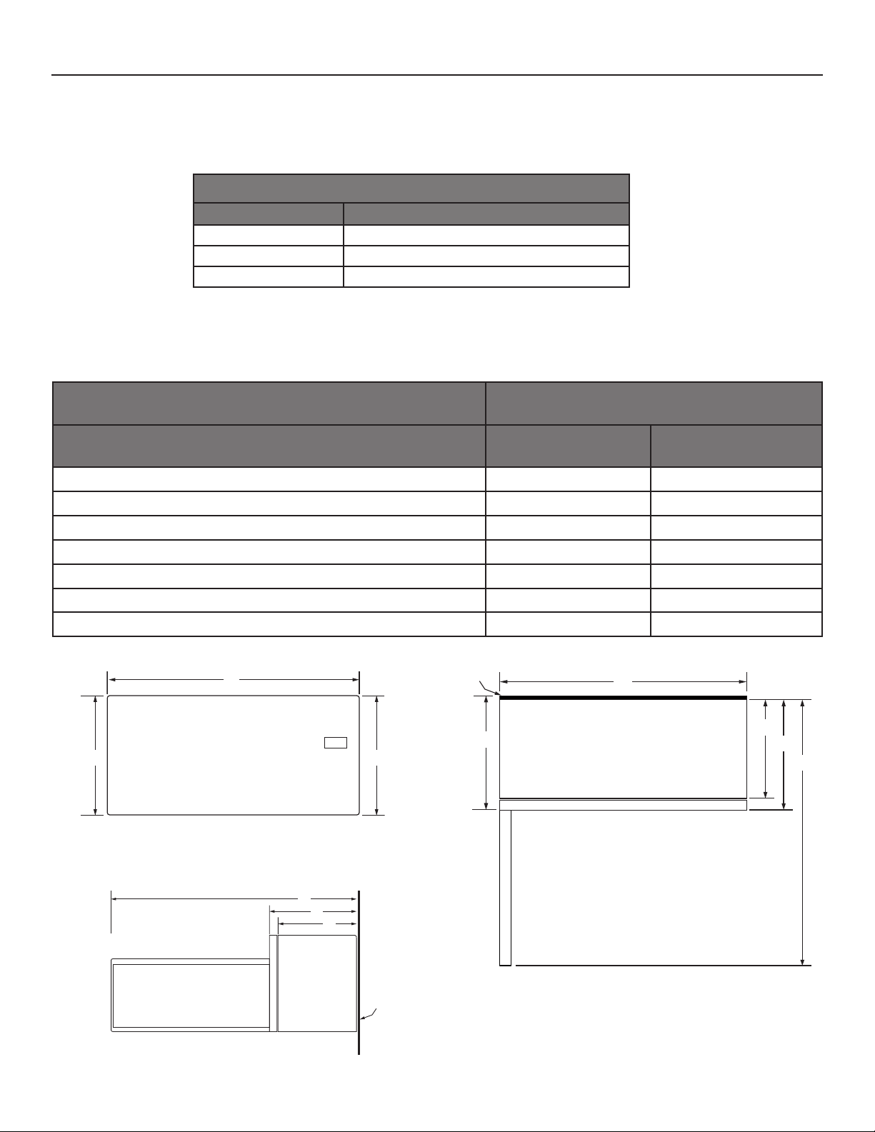
PRODUCT DIMENSIONS
Model# |
|
|
|
|
|
|
|
|
|
|
|
|
|
|
|
|
|
UMV1170L |
||||||||||||||||||||||
|
|
|
|
|
|
|
|
|
|
|
|
|
|
|
|
|
|
|
|
|
|
|
|
|
|
|
|
|
|
|
|
|
|
|
|
|
|
|
|
|
Unit of Measurement |
|
|
|
|
|
|
|
|
|
|
|
|
|
|
|
|
in |
|
|
cm |
||||||||||||||||||||
|
|
|
|
|
|
|
|
|
|
|
|
|
|
|
|
|
|
|
|
|
|
|
|
|
|
|
|
|
|
|
|
|
|
|
|
|
|
|
|
|
Overall width (A) |
|
|
|
|
|
|
|
|
|
|
|
30 |
|
|
76 |
|
|
|
|
|
|
|
|
|
|
|||||||||||||||
|
|
|
|
|
|
|
|
|
|
|
|
|
|
|
|
|
|
|
|
|
|
|
|
|
|
|
|
|
|
|
|
|
|
|
|
|
|
|
|
|
Overall height (B) |
|
|
|
|
|
|
|
|
|
|
|
|
|
|
|
|
171∕8 |
|
|
43.5 |
|
|
|
|
|
|
|
|
|
|||||||||||
Height of the door (C) |
|
|
|
|
|
|
|
|
|
|
|
|
|
|
|
|
123∕4 |
|
|
32.3 |
|
|
|
|
|
|
|
|
|
|||||||||||
Depth without door (D) |
|
|
|
|
|
|
|
|
|
|
|
|
|
|
|
|
141∕8 |
|
|
35.9 |
|
|
|
|
|
|
|
|
|
|||||||||||
Depth with door (E) |
|
|
|
|
|
|
|
|
|
|
|
|
|
|
|
|
151∕2 |
|
|
39.3 |
|
|
|
|
|
|
|
|
|
|||||||||||
Depth with door open 90° (F) |
|
|
|
|
|
|
|
|
|
|
|
|
|
|
|
|
393∕8 |
|
|
100 |
|
|
|
|
|
|
|
|
|
|||||||||||
Depth with Bump Out Kit (G) |
|
|
|
|
|
|
|
|
|
|
|
16 |
|
|
40.6 |
|
|
|
|
|
|
|
|
|
||||||||||||||||
|
|
|
|
|
|
|
|
|
|
|
|
|
|
|
|
|
|
|
|
|
|
|
|
|
|
|
|
|
|
|
|
|
|
|
|
|
|
|
|
|
|
|
|
|
|
|
|
|
|
|
|
|
|
|
|
|
|
Bump out |
|
|
|
|
|
|
|
|
|
|
|
|
|
|
|
|
|||||||
|
|
|
|
|
|
|
|
A |
|
|
|
|
|
|
|
|
Kit |
|
|
A |
|
|
|
|
|
|
|
|
|
|
|
|||||||||
|
|
|
|
|
|
|
|
|
|
|
|
|
|
|
|
|
|
|
|
|
|
|
|
|
|
|
|
|
|
|
|
|
|
|
|
|
|
|
|
|
|
|
|
|
|
|
|
|
|
|
|
|
|
|
|
|
|
|
|
|
|
|
|
|
|
|
|
|
|
|
|
|
|
|
|
|
|
|
|
|
|
|
|
|
|
|
|
|
|
|
|
|
|
|
|
|
|
|
|
|
|
|
|
|
|
|
|
|
|
|
|
|
|
|
|
|
|
|
|
|
|
|
|
|
|
|
|
|
|
|
|
|
|
|
|
|
|
|
|
|
|
|
|
|
|
|
|
|
|
|
|
|
|
|
|
D |
|
|
|
|
|
||
|
|
|
|
|
|
|
|
|
|
|
|
|
|
|
|
|
|
|
|
G |
|
|
|
|
|
|
|
|
|
|
|
|
|
|
|
|
||||
|
|
|
|
|
|
|
|
|
|
|
|
|
|
|
|
|
|
|
|
|
|
|
|
|
|
|
|
|
|
|
|
|
|
|
|
|||||
|
|
|
|
|
|
|
|
|
|
|
|
|
|
|
|
|
|
|
|
|
|
|
|
|
|
|
E |
|
|
|
||||||||||
|
|
|
|
|
|
|
|
|
|
|
|
|
|
|
|
|
|
|
|
|
|
|
|
|
|
|
|
|
|
|
|
|
|
|
|
|
||||
|
|
C |
|
|
|
|
|
|
|
|
|
|
B |
|
|
|
|
|
|
|
|
|
|
|
|
|
|
|
|
|
|
|
|
|
|
F |
|
|||
|
|
|
|
|
|
|
|
|
|
|
|
|
|
|
|
|
|
|
|
|
|
|
|
|
|
|
|
|
|
|
|
|
|
|
|
|
|
|
||
|
|
|
|
|
|
|
|
|
|
|
|
|
|
|
|
|
|
|
|
|
|
|
|
|
|
|
|
|
|
|
|
|
|
|
|
|
|
|
|
|
|
|
|
|
|
|
|
|
|
|
|
|
|
|
|
|
|
|
|
|
|
|
|
|
|
|
|
|
|
|
|
|
|
|
|
|
|
|
|
|
|
|
|
|
|
|
|
|
|
|
|
|
|
|
|
|
|
|
|
|
|
|
|
|
|
|
|
|
|
|
|
|
|
|
|
|
|
|
|
|
|
|
|
|
|
|
|
|
|
|
|
|
|
|
|
|
|
|
|
|
|
|
|
|
|
|
|
|
|
|
|
|
|
|
|
|
|
|
|
|
|
|
|
|
|
|
|
|
|
|
|
|
|
|
|
|
|
|
|
|
|
|
|
|
|
|
|
|
|
|
|
|
|
|
|
|
|
|
|
|
|
|
|
|
FRONT VIEW
F
E
D
Back of |
TOP VIEW |
Cabinet |
|
SIDE VIEW
W11521615A
DETAILED PLANNING DIMENSION
2 of 8
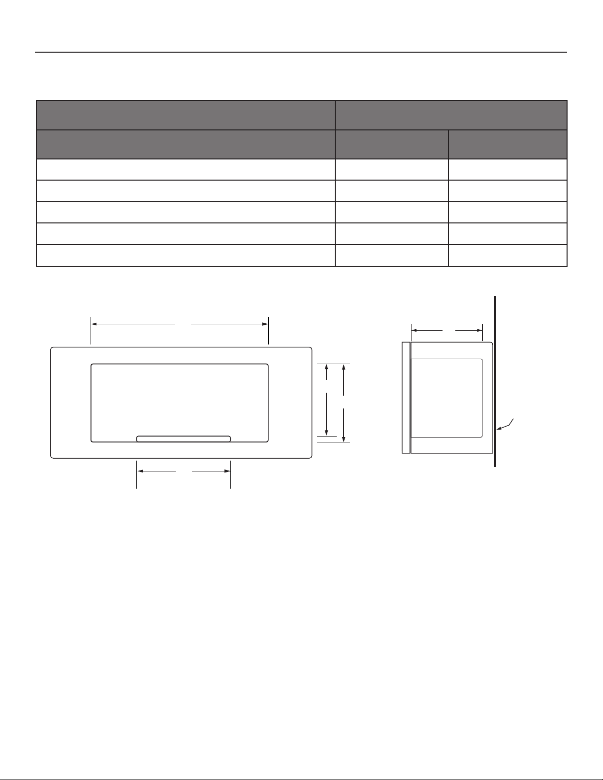
MICROWAVE INTERIOR CAVITY DIMENSIONS
Model# |
|
UMV1170L |
|
|
|
|
|
Unit of Measurement |
in |
|
cm |
|
|
|
|
Cavity height (J) |
91∕2 |
|
24.2 |
|
|
|
|
Cavity height including highest point of the turntable (K) |
99∕16 |
|
24.3 |
|
|
|
|
Cavity width (L) |
211∕8 |
|
53.7 |
|
|
|
|
Cavity depth (M) |
14 |
|
35.6 |
|
|
|
|
Turntable diameter (N) |
12 |
|
30.5 |
|
|
|
|
L |
M |
|
K
J
N
Back of
Cabinet
CAVITY INTERIOR FRONT VIEW |
CAVITY INTERIOR SIDE VIEW |
DETAILED PLANNING DIMENSION
3 of 8
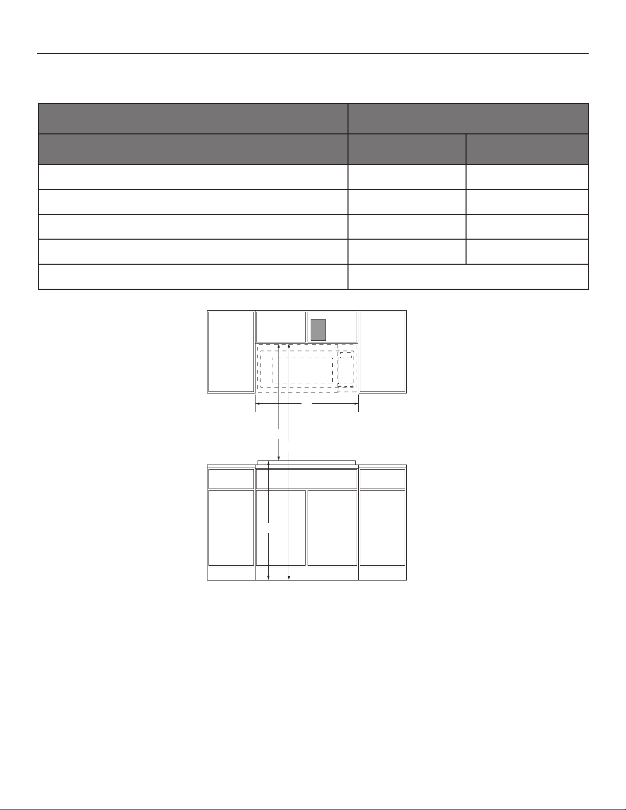
OPENING/CLEARANCE DIMENSIONS
Model# |
|
UMV1170L |
|
|
|
|
|
Opening/Clearance Measurement |
in |
|
cm |
|
|
|
|
Minimum width of cabinet opening (A) |
30 |
|
76.2 |
|
|
|
|
Typical height from cooking surface to floor based on 36" countertops (B) |
36 |
|
91.4 |
|
|
|
|
Typical height from top of cabinet to cooking surface based on 36" |
30 |
|
76.2 |
countertops (C) |
|
||
|
|
|
|
|
|
|
|
Minimum height from floor to top of cabinet opening (B+C=D) (D) |
66 |
|
167.6 |
|
|
|
|
Recommended electrical connection location (E) |
|
See below schematic |
|
|
|
|
|
E |
A |
C |
D |
B |
FRONT VIEW
LOCATION REQUIREMENTS
Support structure must be able to support 150 lb (68 kg) including microwave oven and upper cabinet including contents. Mounting plate must attach to a minimum of one 2" x 4" (5.1 cm x 10.2 cm) wall stud.
Mounting distance between a fixed wall on the higed-side of the door and the microwave oven is 1/2" (1.3 cm)
VENTING REQUIREMENTS
The microwave oven is factory set for recirculating ventilation.
To vent through the roof or wall, refer to installation instructions for further information.