

DETAILED PLANNING DIMENSION
Back of
Bump out
Ki
ELECTRICAL REQUIREMENTS
WARNING: To reduce the risk of re, electric shock, or injury to persons, read the IMPORTANT SAFETY INSTRUCTIONS and
INSTALLATION INSTRUCTIONS, located in your appliance's Owner's Manual, before installing and operating this appliance.
Electrical Requirements
Model# UMV1170L
Amperage Rating 15 - 20 A
Operating Voltage 120 V
Operating Frequency 60 Hz
NOTE: A time-delay fuse or dedicated circuit is recommended. Do not use an extension cord.
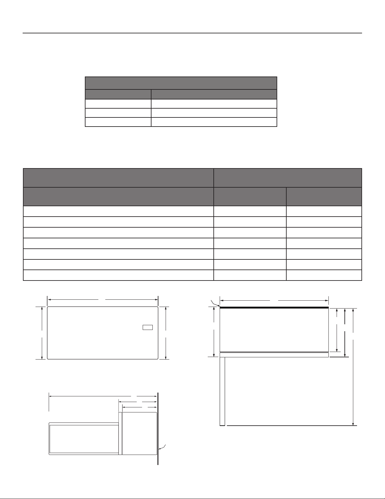
PRODUCT DIMENSIONS
Model# UMV1170L
Unit of Measurement in cm
1 of 8
Overall width (A) 30 76
Overall height (B) 171∕
Height of the door (C) 123∕
Depth without door (D) 141∕
Depth with door (E) 151∕
Depth with door open 90° (F) 393∕
8
4
8
2
8
43.5
32.3
35.9
39.3
100
Depth with Bump Out Kit (G) 16 40.6
A
t
A
G
BC
FRONT VIEW
D
E
F
SIDE VIEW
F
E
D
Cabinet
TOP VIEW
W11521615A
DETAILED PLANNING DIMENSION
Back of
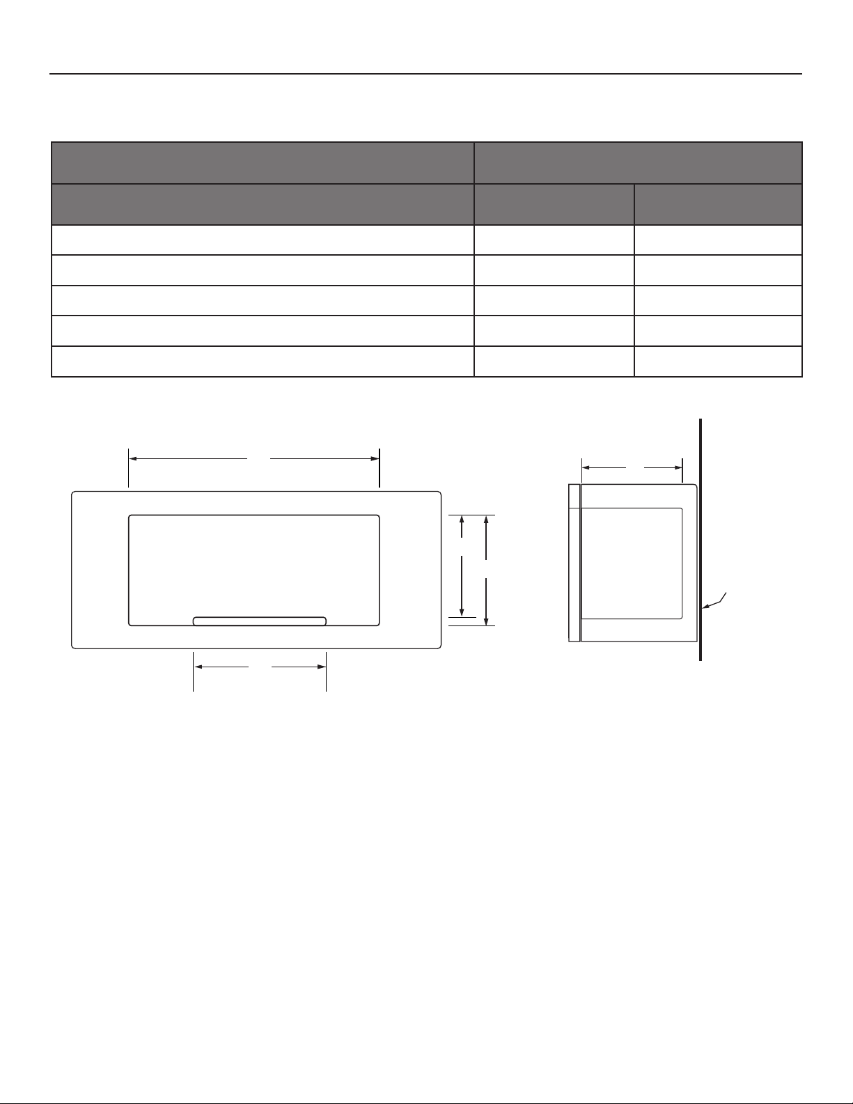
MICROWAVE INTERIOR CAVITY DIMENSIONS
Model# UMV1170L
Unit of Measurement in cm
2 of 8
Cavity height (J) 91∕
Cavity height including highest point of the turntable (K) 99∕
Cavity width (L) 211∕
Cavity depth (M) 14 35.6
Turntable diameter (N) 12 30.5
L
2
16
8
24.2
24.3
53.7
M
K
J
Cabinet
N
CAVITY INTERIOR FRONT VIEW
CAVITY INTERIOR SIDE VIEW
DETAILED PLANNING DIMENSION
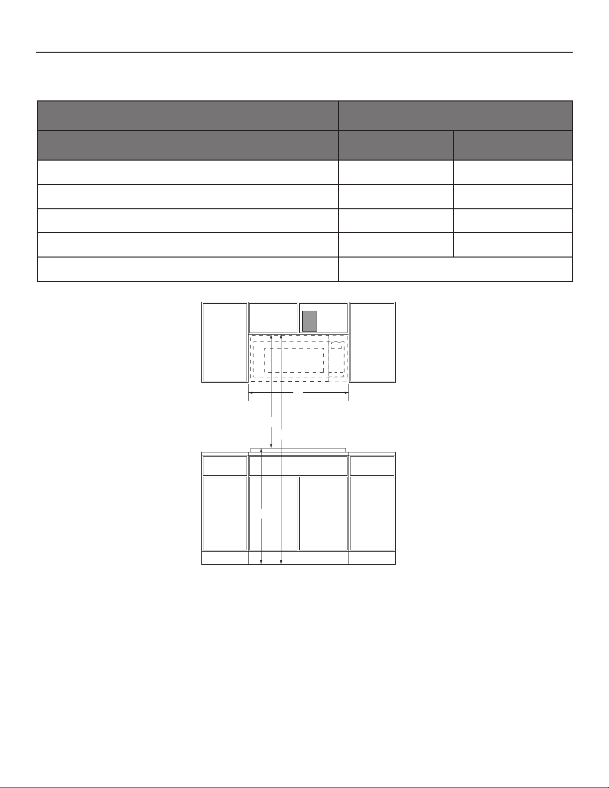
OPENING/CLEARANCE DIMENSIONS
Model# UMV1170L
Opening/Clearance Measurement in cm
Minimum width of cabinet opening (A) 30 76.2
Typical height from cooking surface to oor based on 36" countertops (B) 36 91.4
3 of 8
Typical height from top of cabinet to cooking surface based on 36"
countertops (C)
Minimum height from oor to top of cabinet opening (B+C=D) (D) 66 167.6
Recommended electrical connection location (E) See below schematic
E
A
C
D
30 76.2
B
FRONT VIEW
LOCATION REQUIREMENTS
Support structure must be able to support 150 lb (68 kg) including microwave oven and upper cabinet including contents.
Mounting plate must attach to a minimum of one 2" x 4" (5.1 cm x 10.2 cm) wall stud.
Mounting distance between a xed wall on the higed-side of the door and the microwave oven is 1/2" (1.3 cm)
VENTING REQUIREMENTS
The microwave oven is factory set for recirculating ventilation.
To vent through the roof or wall, refer to installation instructions for further information.

DETAILED PLANNING DIMENSION
12"
DEPTH
14"
e
t
14"
DEPTH
15"
Bump Out Mounting Plate
OPENING/CLEARANCE DIMENSIONS
Model# UMV1170L
Opening/Clearance Measurement in cm
Depth of upper cabinet (minimum - maximum) *(F) 12-15 30.5-38.1
Can this product be installed ush?
Flush refers to the appliance not protruding past the cabinet depth. (Y/N)
* This microwave oven is factory set for 12" - 14" depth of upper cabinet, install with the provided mouting plate.
For 15" depth of upper cabinet, install with the optional bump out mounting kit W11185746, the bump out mounting kit is not
provided, but can be purchased from Whirlpool.
N
4 of 8
Side
Cabinet
F
SIDE VIEW
Mounting Plat
Side
Cabinet
F
SIDE VIEW
Bump out
mounting ki
Mounting Plate
IMPORTANT: Dimensional specications are provided for planning purposes only.
Do not make any cutouts based on this information. Refer to the Installation Guide before selecting cabinetry, verifying electrical/gas
connections, making cutouts or beginning installation.
All Whirlpool® appliances are appropriately UL, CUL or CSA approved.

DIMENSIÓN DE PLANIFICACIÓN EN DETALLE
Parte posterior
Kit de montaje
sobresalient
5 de 8
REQUISITOS ELÉCTRICOS
ADVERTENCIA: A n de reducir el riesgo de incendio, choque eléctrico o lesiones personales, lea las INSTRUCCIONES IMPORTANTES
DE SEGURIDAD Y LAS INSTRUCCIONES DE INSTALACIÓN, que se encuentran en el Manual del propietario, antes de instalar y usar el
electrodoméstico.
Requisitos eléctricos
N.° de modelo UMV1170L
Índice de amperaje 15 - 20 A
Voltaje de funcionamiento 120 V
Frecuencia de funcionamiento 60 Hz
NOTA: Se recomienda un fusible retardador o un disyuntor dedicado. No use un cable de extensión.
DIMENSIONES DEL PRODUCTO
N.° de modelo UMV1170L
Unidad de medida pul cm
Ancho total (A) 30 76
Altura total (B) 171∕
Altura de la puerta (C) 123∕
Profundidad sin puerta (D) 141∕
Profundidad con puerta (E) 151∕
Profundidad con puerta abierta a 90° (F) 393∕
Profundidad sin kit de montaje sobresaliente (G) 16 40,6
A
VISTA FRONTAL
8
4
8
2
8
e
A
43,5
32,3
35,9
39,3
100
D
BC
G
E
F
F
E
D
VISTA LATERAL
del gabinete
VISTA SUPERIOR

DIMENSIÓN DE PLANIFICACIÓN EN DETALLE
Parte posterior
DIMENSIONES DE LA CAVIDAD INTERIOR DEL MICROONDAS
N.° de modelo UMV1170L
Unidad de medida pul cm
6 de 8
Altura de la cavidad (J) 91∕
Altura de la cavidad desde el punto más alto de la bandeja giratoria (K) 99∕
Ancho de la cavidad (L) 211∕
Profundidad de la cavidad (M) 14 35,6
Diámetro de la bandeja giratoria (N) 12 30,5
L
2
16
8
24,2
24,3
53,7
M
K
J
del gabinete
N
VISTA FRONTAL DE LA CAVIDAD INTERIOR
VISTA LATERAL DE LA CAVIDAD INTERIOR

DIMENSIÓN DE PLANIFICACIÓN EN DETALLE
MEDIDAS DE ABERTURA/ESPACIO
N.° de modelo UMV1170L
Medidas de la abertura/espacio pul cm
Ancho mínimo de la apertura del gabinete (A) 30 76,2
7 de 8
Altura típica desde la supercie de cocción hasta el piso según mostradores
de 36" (B)
Altura típica desde la parte superior del gabinete hasta la supercie de cocción
según mostradores de 36" (C)
Altura mínima desde al piso hasta la parte superior de la abertura del gabinete
(B+C=D) (D)
Ubicación recomendada para la conexión eléctrica (E) Consulte el esquema que aparece a continuación
E
A
C
D
36 91,4
30 76,2
66 167,6
B
VISTA FRONTAL
REQUISITOS DE UBICACIÓN
La estructura de soporte debe poder sostener un peso de 150 libras (68kg) incluido el peso del horno de microondas, el gabinete y sus contenidos.
La placa de montaje debe jarse como mínimo a una viga de pared de 2" x 4" (5,1cm x 10,2cm).
La distancia de montaje entre una pared ja del lado de la puerta con bisagras y el horno de microondas es de 1/2" (1,3 cm)
REQUISITOS DE VENTILACIÓN
El horno de microondas está congurado de fábrica en ventilación recirculante.
Para obtener más información para instalar la ventilación en la pared o en el techo, consulte las instrucciones de instalación.

DIMENSIÓN DE PLANIFICACIÓN EN DETALLE
12" ≤ PROFUNDIDAD ≤ 14"
Placa de montaje
14" ≤ PROFUNDIDAD ≤ 15"
Placa de montaje
sobresaliente
8 de 8
MEDIDAS DE ABERTURA/ESPACIO
N.° de modelo UMV1170L
Medidas de la abertura/espacio pul cm
Profundidad del gabinete superior (mín. - máx.)* (F) 12-15 30,5-38,1
¿Este producto se puede instalar al ras?
Al ras signica que el electrodoméstico no sobresale del gabinete. (S/N)
* Este horno de microondas está congurado de fábrica para un gabinete superior de 12" - 14" de profundidad, instalar con la placa
de montaje proporcionada.
Para gabinetes superiores de 15" de profundidad, instalar con el kit de montaje sobresaliente opcional W11185746. No se incluye el kit
de montaje sobresaliente, pero puede adquirirse en Whirlpool.
N
Gabinete
lateral
F
VISTA LATERAL
Gabinete
lateral
Kit de montaje
sobresaliente
F
VISTA LATERAL
Placa de montaje
IMPORTANTE: Las especicaciones de medidas son solo para nes de planicación.
No realice ningún corte basado en esta información. Consulte la Guía de instalación antes de la selección de gabinetes, vericar las
conexiones eléctricas/de gas, realizar cortes o iniciar la instalación.
Todos los electrodomésticos Whirlpool® poseen la homologación UL, CUL o CSA pertinente.
©2021 All rights reserved.
W11521615A
Todos los derechos reservados.
04/
21
 Loading...