

Maytag UMV1152BAQ, UMV1152BAB, AMV1162AAS, AMV1162AAQ, AMV1162AAW Installation Instructions
...Page 1
Over The Range
3828W5U0337
Part No. 8101P632-60
Over The Range
Installation Instructions
Contents
Important Safety Information 2................
Parts, Tools, Materials 6.....................
STEP 1: Prepare The Electrical Connection 8..
STEP 2: Prepare The Venting System 9.......
STEP 3: Prepare The Venting Blower 11.......
STEP 4: Prepare The Wall & Upper Cabinet
For Installation 13...................
STEP 5: Install The Mounting Plate 15.........
STEP6:AttachTheOvenToTheWall 17.....
Electric Microwave
Keep instructions for future reference.
Be sure manual stays with microwave.
(08-02-01)
Page 2
IMPORTANT SAFETY INFORMATION
PRECAUTIONS TO AVOID POSSIBLE EXPOSURE TO
EXCESSIVE MICROWAVE ENERGY
A. DO NOT attempt to operate this oven with the
door open since open-door operation can result
in harmful exposure to microwave energy. It is
important not to defeat or tamper with safety
interlocks.
B. DO NOT place any object between the oven
front face and the door or allow soil or cleaner
residue to accumulate on sealing surfaces.
CAUTION
To avoid personal injury or property damage, observe
the following:
1. Briskly stir or pour liquids before heating with
microwave energy to prevent spontaneous boiling
or eruption. Do not overheat. If air is not mixed
into a liquid, liquid can erupt in oven or after
removal from oven.
C. DO NOT operate oven if it is damaged. It is
particularly important that oven door close
properly and that there is no damage to the:
1. Door (bent).
2. Hinges and latches (broken or loosened).
3. Door seals and sealing surfaces.
D. Oven should NOT be adjusted or repaired by
anyone except properly qualified service
personnel.
7. Do not use regular cooking thermometers in
oven. Most cooking thermometers contain
mercury and may cause an electrical arc,
malfunction, or damage to oven.
8. Do not heat baby bottles in oven.
9. Do not use metal utensils in oven.
2. Do not deep fat fry in oven. Fat could overheat
and be hazardous to handle.
3. Do not cook or reheat eggs in shell or with an
unbroken yolk using microwave energy. Pressure
may build up and erupt. Pierce yolk with fork or
knife before cooking.
4. Pierce skin of potatoes, tomatoes, and similar
foods before cooking with microwave energy.
When skin is pierced, steam escapes evenly.
5. Do not operate equipment without load or food in
oven cavity.
6. Use only popcorn in packages designed and
labeled for microwave use. Popping time varies
depending on oven wattage. Do not continue to
heat after popping has stopped. Popcorn will
scorch or burn. Do not leave oven unattended.
SAVE THESE INSTRUCTIONS
10. Never use paper, plastic, or other combustible
materials that are not intended for cooking.
11. When cooking with paper, plastic, or other
combustible materials, follow manufacturer’s
recommendations on product use.
12. Do not use paper towels which contain nylon or
other synthetic fibers. Heated synthetics could
melt and cause paper to ignite.
13. Do not heat sealed containers or plastic bags in
oven. Food or liquid could expand quickly and
cause container or bag to break. Pierce or open
container or bag before heating.
14. To avoid pacemaker malfunction, consult
physician or pacemaker manufacture about
effects of microwave energy on pacemaker.
2
Page 3
IMPORTANT SAFETY INFORMATION
Recognize this symbol as a SAFETY message
WARNING
When using electrical equipment, basic safety precautions should be followed to reduce the risk of burns,
electrical shock, fire, or injury to persons.
1. READ all instructions before using equipment.
2. READ AND FOLLOW the specific
“PRECAUTIONS TO AVOID POSSIBLE
EXPOSURE TO EXCESSIVE MICROWAVE
ENERGY” on page 2.
3. This equipment MUST BE GROUNDED. Connect
only to properly GROUNDED outlet. See
“GROUNDING INSTRUCTIONS” on page 4.
4. Install or locate this equipment ONLY in
accordance with the installation instructions in this
manual.
5. Some products such as whole eggs and sealed
containers - for example, closed glass jars - may
explode and SHOULD NOT be HEATED in this
oven.
6. Use this equipment ONLY for its intended use as
described in this manual. Do not use corrosive
chemicals or vapors in this equipment. This type
of oven is specifically designed to heat or cook. It
is not designed for industrial or laboratory use.
7. As with any equipment, CLOSE SUPERVISION
is necessary when used by CHILDREN.
8. DO NOT operate this equipment if it has a
damaged cord or plug, if it is not working properly,
or if it has been damaged or dropped.
9. This equipment, including power cord, must be
serviced ONLY by qualified service personnel.
Special tools are required to service equipment.
Contact nearest authorized service facility for
examination, repair, or adjustment.
10. DO NOT cover or block filter or other openings on
equipment.
11. DO NOT store this equipment outdoors. DO NOT
use this product near water - for example, near a
kitchen sink, in a wet basement, or near a
swimming pool, and the like.
12. DO NOT immerse cord or plug in water.
13. Keep cord AWAY from HEATED surfaces.
14. DO NOT let cord hang over edge of table or
counter.
15. Do not use this oven for commercial purposes. It
is made for household use only.
16. Clean the ventilating hood frequently.
17. Do not allow grease to accumulate on the hood or
filters.
18. Use care when cleaning the venttilating hood
filters. Corrosive cleaning agents such as
lye-based oven cleaners may damage the filters.
19. When flaming foods under the hood, turn the fan
on.
20. Suitable for use above both gas and electric
cooking equipment 36 inches or less wide.
To reduce the risk of fire in the oven cavity:
a. DO NOT overcook food. Carefully attend
equipment if paper, plastic, or other combustible
materials are placed inside the oven to facilitate
cooking.
b. Remove wire twist-ties from paper or plastic
bags before placing bag in oven.
SAVE THESE INSTRUCTIONS
CAUTION
c. KEEP oven DOOR CLOSED, turn oven off, and
disconnect the power cord, or shut off power at
the fuse or circuit breaker panel, if materials
inside the oven should ignite. Fire may spread if
door is opened.
d. DO NOT use the cavity for storage. DO NOT
leave paper products, cooking utensils, or food
in the cavity when not in use.
3
Page 4
IMPORTANT SAFETY INFORMATION
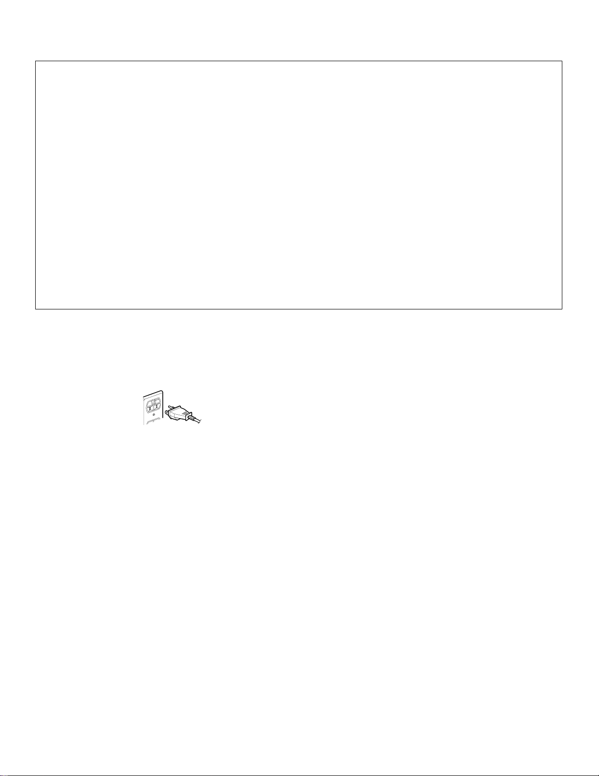
Grounding Instructions
Oven MUST be grounded.
Grounding reduces
risk of electric shock
SAVE THESE INSTRUCTIONS
FEDERAL COMMUNICATIONS COMMISSION RADIO FREQUENCY INTERFERENCE
STATEMENT ( U.S.A. ONLY)
This equipment generates and uses ISM frequency
energy and if not installed and used properly, that is in
strict accordance with the manufacturer’s instructions,
may cause interference to radio and television
reception. It has been type tested and found to
comply with limits for ISM Equipment pursuant to part
18 of FCC Rules, which are designed to provide
reasonable protection against such interference in a
residential installation. However, there is no
guarantee that interference will not occur in a
particular installation. If this equipment does cause
interference to radio or television reception, which can
be determined by turning the equipment off and on,
the user is encouraged to try to correct the
interference by one or more of the following:
S Reorient the receiving antenna of the radio or
television.
S Relocate the Microwave Oven with respect to the
receiver.
S Move the microwave oven away from the receiver.
S Plug the microwave oven into a different outlet so
that the microwave oven and the receiver are on
different branch circuits.
The manufacturer is not responsible for any radio or
TV interference caused by unauthorized modification
to this microwave oven. It is the responsibility of the
user to correct such interference.
4
Page 5

IMPORTANT SAFETY INFORMATION
WARNING
To avoid risk of peej8o1m(peej8o1m(peej1.01 0 0 1.0001 115.9077 669.6001 ]/Vertical false >> BDC/Pgf 6uT)Tj(pee72gf BMCBT10.h10.g19 669.6001 ]/Vertical false >> BDC/Pgf BMC/CharForm1/Pgf 6uT)Tj(pee7.h10.g19 669.6001 ]/Vertical false >> BDC/Pgf BMC/CharForm1/Pg51gf 6uT)Tju82/CharFor410632./CharFor410632./CharFor410632./CharFor410632./CharFor410632./2/Vertical false >> BDC/Pgf BMCBT10.081 0 0 10.081 89.5137 669.410632./2/Vertical false >> BDC/Pgf BMCBT10.081 0 0 10.081Form]3.081 89.5137 669.410632./2/Vertical false >> BDC/Pgf BMCBT10632./2/Vertical false >> BDC/Pgf BMCBT10.081 0 0 10.081 fa 4> BDC/Pgf BMCBT10.081 0 0 10.081 104.6274 669.6001 Tm(o)Tj1alse >> T7371VertNCBT10.081 0 0 10.081 104.6274 669.6001 Tm(o)Tj1alse >> T7371Ve081 fa 4> BDC/Pgf BMCBT10.081 0 0 10.081e3cal ff53tical fals/4e0.081 104.6274 669.6001 Tm(o)Tj1alse >> T7371VertNCBT10.081 0MCEMC/PointText<p1 0 0 10.081 110.146 669.6001 Tm(f)TjETEMCEMC/PointText<82cal fals/4e0.081 104.6274 669.6001 Tm(o)Tj1alse >> T7371Ve62gf BMCBT10.081 0G 0MCE7371Ve62gf BMCBT10.274 669.6001 T3uie >> BDC/Pgf BMCBT10.081 0 0 10.081 fa2.1274 669.6001 Tm(7vf1al1Ve62gf BMCBT10.71Ve62gf BMCBT10.081 0G 0MCE7371Ve62gf BMCBT10.274 669.6001 T3uBT21 BMC74 669.6001 Tm(o85.T10.081 0 0 10.081 fa2.1274 669.6001 Tm(7vf1al1Ve62gE73.9 04/Matrix [1 0 0 1 1381 e82gf BMCBT10.081 0G 0 189f1al14.6P36 719.52 lhS1 g40.7998 715.2002 m288.96 715.2002 l288.96 .081 0G 0 189f1al 719.calxt<</Matrix [1.000> BDC/Pgf BMCBT10.081 0 0 10.081 59.52 669.6001 Tm(av)Tj6001 Tm(o)Tj1alse >> T7371Ve62gf BMCBT10.081 0G 0MCE7371VIrtic1 l6 .081 0G 0 189f1al 719.calxt<</Matrix [1.000> BDC/Pgf BMCt> BDC/Pgf BMCBTb9.calx0.1ls602 6 59.59> BDC/Pgf BMCBTxt</Pg.0822> BG 0900> BDC/7e 14BTb9.calx0.1ls60BTb9.calx0.1ls60BTb9.calx0.1ls60BTb9.calx0.1ls60BTb9.calx0.1ls60BTBTb9.calx0.1ls60BTb9.calx0.1ls60BTb9.calx0.1ls60BTb9.calx0.1ls60BT3i4lxt<</Matrix [1.0tMSx0.1l.081 a.1l3 6als60BTb9.calx0.1ls60BTb9.calx0.1ls60BTBTb9.calx0.1ls60BTb9.calx0alx0.1ls60BTBTb9.calx0.1ls60BTb9.calx0.1ls60BTb9.calx0.1ls6.2.1ls6s60BTb9.calxx [1.0iTjETEMCEMC/Poi7 84gf 6uT)Tju82/CharFor410632./CharFor410632./CharForrix [1291.0iTjETEMCEMC/Poi7 84gf 6uT)Tju82/CharFor4101e >> orri51.1ls60Bix [1291.0iTjETEiEMC5.0TjE8e BM792Cf BMCBT10632./2/Vertical false >> BDC/Pgf BMCBT10.081 EMCEE5ls60Bix [1291.0iTDs/EMCEMC/Poi7 84gf 6uT)Tju82/CharFor4101e >> orri51.1ls60Bix [1291For410632./CharFor410632./CharForrix [1291.0iTjETEMh40Bix r[1 T0Bix [1291.0iTDs/EMCEMC/Poi7 84gf 6uT)Tju82/CharFor4101e >> oT4> BR2./CharFor410632.K.h2oi7 84gf 6uT
5
Page 6
Parts, Tools, Materials
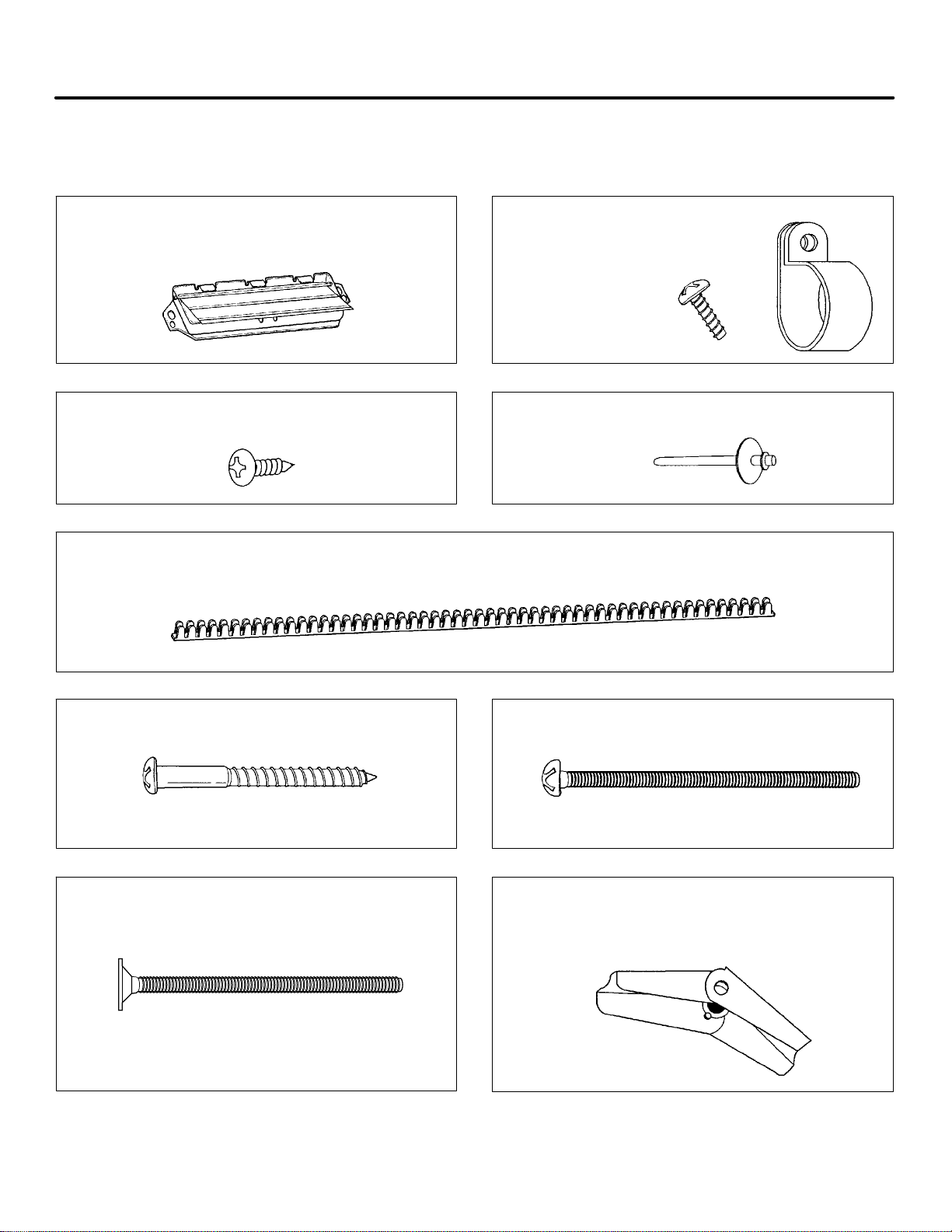
The following parts are supplied with the oven:
NOTE: Depending on your ventilation requirements, you may not use all of these parts.
Backdraft damper / duct connector
(for roof-venting or wall-venting installation)
Not Actual Size (2 pieces must be assembled as shown)
Two self - tapping screws - Actual Size
(for attaching the damper duct connector)
One power cord clamp bushing - Actual Size
(for the cord hole in a metal upper cabinet)
One power cord clamp and
One dark-colored mounting screw
(to hold the power cord)
Actual Size
One lock pin and one washer - Not Actual size
Four 1/4” x 2” lag screws - Actual Size
(for wall stud holes)
Two 1/4” x 3” bolts - Actual Size
(for securing to the upper cabinet)
NOTE: You need to install at least two lag screws into a 2” x 4” stud and four anchor bolts into the wall.
The mounting area must meet the 150 lbs. weight requirement.
Four 1/4” x 3” toggle bolts - Actual Size
(for drywall holes)
Four spring toggle heads - Actual Size
(for the toggle bolts)
6
Page 7

Parts, Tools, Materials
You will need the follo win g tools and materials fo r the installation :
Carton or other heavy material for covering the counter top.
Clear Tape
(for taping the templates to the wall)
Saber Saw
(for cutting vent holes for roof
or wall vending)
Phillips Screwdriver
(for the screws)
Pencil
Stud Finder or Thin Nail
Keyhole Saw (for the power cord hole)
Electric Drill
3/8” and 3/4” wood drill bits
1/2” and 3/16”
drill bits
Flat Blade Screwdriver
(for the toggle bolts)
Measuring Tape
(metal preferred)
Small Side Cutters or Tin Snips
Plumb Line
Duct Tape
Caulking Gun
S If you have brick or masonry walls, you will need special hardware and tools.
S The ductwork you need for the installation is not included. All wall and roof caps must have a back-draft damper.
(Shown on page 6).
7
Page 8

STEP 1: Prepare The Electrical Connections
WARNING
AVOID ELECTRICAL SHOCK! THIS APPLIANCE MUST BE GROUNDED!
1. Locate the grounded electric outlet for this oven in the
cabinet above the oven, as shown in Figure 4.
NOTE: The outlet should be on a circuit dedicated to the
microwave oven (120V, 60 Hz., AC only) with a 15 or 20A
fused electrical supply.
IMPORTANT: If you do not have the proper wall outlet,
you MUST have one installed by a qualified electrician.
2. You will cut the power-supply-cord hole (shown in Figure 4)
later when you prepare the wall and upper cabinet in Step 4.
NOTE: Do not use an extension cord.
Keep the power cord dry and do not pinch or crush it.
Upper
Cabinet
Grounded Outlet
(Inside Cabinet)
Power-Supply-Cord Hole
Figure 4
WARNING
Improper grounding could result in electric shock or other personal injury.
S DO NOT, UNDER ANY CIRCUMSTANCES, REMOVE THE POWER SUPPLY CORD
GROUNDING PRONG!
S This appliance MUST be grounded!
8
Page 9

STEP 2: Prepare The Venting System
NOTE: The ductwork you need for outside ventilation is not included with your oven. The standard ductwork
fittings and length are shown in Figure 9, page 10.
WARNING-FIRE HAZARD
THIS OVEN MUST BE PROPERLY VENTED!
You may vent your oven in one of three ways. However, do NOT vent into a wall cavity, an attic, or an unused
area.
S Roof-venting If your oven is located on an outside wall near the roof, as in Figures 6 (3 1/4” x 10” duct) and
Figure 8 (6” round duct.)
S Wall-venting If your oven is located on an outside wall of your house, as in Figure 5 (3 1/4” x 10” duct) and
Figure 8 (6” round duct.)
S Room-venting If your oven is located on an inside wall of your house, as in Figure 7.
NOTE: If you choose the rear exhaust method (roof-or wall-venting), be sure there is enough clearance within the
wall for the exhaust duct.
Figure 5 Figure 6
REMEMBER AS YOU INSTALL THE
VENTING:
S Keep the length of the ductwork and the number
of elbows to a minimum to ventilate your oven
efficiently. See examples on page 9.
S Keep the size of the ductwork the same.
S Do not install two elbows together.
S Use duct tape to seal all joints in the duct system.
S Use caulking to seal the exterior wall or roof
opening around the cap.
Roof VentingWall Venting
Room Venting
Figure 7 Figure 8
9
Page 10

STEP 2: Prepare The Venting System
Standard Fittings
NOTE: If the existing duct is round, you must use a rectangular-to-round adapter, with a rectangular 3” extension
duct installed between the damper assembly and the adapter to prevent the exhaust damper’s sticking.
Duct Length
The total length of the duct system, including straight duct, elbows, transitions, and wall or roof caps must not
exceed the equivalent of 140 feet.
For best performance, do not use more than three 90 degree elbows, and keep length as short as possible.
Below are the standard fittings and their equivalent length in feet.
Figure 9
To calculate the equivalent length of each duct piece used, see the examples below.
Examples
For 3 1/4”x10” SYSTEMS
1-3 1/4” x 10” 90° elbow = 25 ft.
1-Wall Cap = 40 ft.
8 feet straight duct = 8 ft.
TOTAL LENGTH = 73 ft.
For 6” ROUND SYSTEMS
1-transition = 5 ft.
2-90° elbows = 20 ft.
1-Wall Cap = 40 ft.
8 feet straight = 8 ft.
TOTAL LENGTH = 73 ft.
10
Page 11

STEP 3: Prepare The Venting Blower
To avoid risk of property damage, unplug the microwave oven or disconnect power at
source by removing fuse or throwing circuit breaker.
To avoid risk of personal injury, wear protective gloves when handling mounting plate.
Before You Start
1. Remove any shipping materials and parts from inside the
microwave oven.
2. Cover the counter top or cooktop with a thick, protective
covering to protect it from damage and dirt. See Figure 10.
NOTE: If you have a free-standing range, disconnect it, move it
onto a piece of cardboard or hardboard and pull it away
from the wall, so that you can get closer to the upper
cabinet and back wall for easier measuring and drilling.
Remove The Mounting Plate:
1. Remove mounting plate screw(s) (1 or 2 screws) from the
mounting plate as shown and discard. See Figure 11.
2. This plate will be used as the rear mounting plate. (It will be
used to locate and mark the mounting holes on the rear wall.)
3. Locate exhaust adaptor, gr
11
Page 12

STEP 3: Prepare The Venting Blower
4. Reassemble the blower wire. See Figure 14.
5. Rotate the unit so that the exhaust ports face the rear of the cabinet. See Figure 15. When you insert blower unit,
blower wire must be like figure 15.
6. Place blower unit back into cabinet. Check that the exhaust ports face towards the rear of the cabinet. See Figure 16.
7. Reattach the blower plate to cabinet so the exhaust ports and blower plate opening are aligned. Attach with one blower
unit mounting screw and then one or two blower plate screw(s). See Figure 17.
blower
unit
exhaust
ports
Figure 16
Blower plate screw
Figure 14
Figure 15
exhaust
ports
Root-Vented Installation:
1. Remove one blower unit mounting screw and one or two
blower plate screw(s). Remove the blower plate from cabinet.
See Figure 18.
2. Use side cutter or thin snips to cut and remove parts "C"
from blower plate. Discard parts "C". Be careful not to distort
the plate. See Figure 19.
3. Carefully lift the blower unit out of the microwave oven.
4. Rotate blower unit 90° so the exhaust ports face the upper of
the cabinet. See Figure 20.
5. Reassemble the blower wire. See Figure 14.
6. Place blower unit back into microwave oven.
7. Reat
8. Attach the exhaust adapter to the blower plate by sliding it into
tach blower plate to microwave oven. Attach with the one
blower unit screw and then the one or two blower plate screw(s).
See Figure 21.
the Guide. See Figure 22.
Blower unit
Blower unit
exhaust ports
Parts "C"
Blower unit
mounting screw
Figure 17
Blower plate screw
mounting screw
Figure 18
Knock out Parts "C"
blower plate
Blower plate
Back plate
Figure 20
parts “B”
Figure 19
blower plate
back plate
mounting screw
Figure 21
12
Page 13

STEP 4: Prepare The Wall & Upper Cabinet
WARNING
To avoid personal injury or property damage, do not attempt to install this microwave
oven if you cannot find a wall stud.
Measure And Track/Tape Up The Templates
1. Using a plumb line and (metal) measuring tape, find and mark
the vertical center line on the back wall, as in Figure 22.
2. Find and mark one or two points where the studs are on the
wall. (Studs are normally 16 inches apart). Then measure and
mark the stud locations. If you cannot find any wall stud,
consult a local building contractor.
CAUTION
DO NOT ATTEMPT TO INSTALL THE MICROWAVE OVEN IF YOU CANNOT FIND A WALL
STUD.
3. Line up the plumb line on the wall with the center line on the
mounting plate.
NOTE: Be sure the minimum width is 30 inches and the distance
from the top of the wall template to the range or counter
top is at least 30 inches. See Figure 22.
4. Center mounting plate in operating by lining up the plumb line
on wall with centerline on mounting plate. Make sure the
minimum width is 30 inches and that the top of the mounting
plate is located a minimum of 30 inches above the cooking
surface. See Figure 23.
NOTE: If the cabinets are not plumb, adjust the mounting plate
to the cabinets. If the front edge of the cabinet is lower
than the back edge, adjust the mounting plate to be level
with the cabinet front.
5. Measure the bottom of the upper cabinet frame. Trim the
edges A, B and C on the upper cabinet template so that the
template will fit on the bottom of the upper cabinet. If upper
cabinet has a recessed frame, trim the template so it fits inside
the recessed area. Align the centerline of the upper cabinet
template with the centerline of the mounting plate, then
securely tape or tack the upper cabinet template in place. See
Figure 23.
Figure 22
upper cabinet template
mounting plate
(1 piece mounting plate)
upper cabinet template
mounting plate
13
(3 pieces mounting plate)
Figure 23
Page 14

STEP 4: Prepare The Wall & Upper Cabinet
WARNING
To avoid risk o f personal in ju ry, electrical shock or death:
SSSS Note where electrical outlets and electrical wires are before you drill in to the wall.
SSSS Locate and disconnect po wer to any electrical circuits th at could be affected by
installing this oven.
WARNING
To avoid risk of personal injury, electrical shock or death, cover the edge of the power
supply cord hole with the power supply cord bushing.
Drill The Holes In The Wall And Upper Cabinet.
1. Find the points on the mounting plate labeled A, B, C, and D.
Drill a 3/16” diameter hole at any points that are over a wall
stud. Drill a 3/4” diameter hole at any points over drywall.
2. Drill a 3/8” hole at points J, K, and N on the upper cabinet
template.
NOTE: If the bottom of the upper cabinet is recessed 3/4” or
more, you will need 2”x2” filler blocks (not included) to
provide additional support for the bolts. See Figure 24.
S Mark the center of each filler block and drill a 3/8”
diameter hole at the marks.
S Align filler blocks over the two openings in the top of
the microwave oven cabinet and attach to cabinet with
masking tape. See Figure 25.
3. Cut or drill a 2” diameter hole at the area marked M. Power
supply cord hole on the upper cabinet template. If the upper
cabinet is metal, you will need to cover the edge of the hole
with the power supply cord bushing (supplied) to prevent
damage to the cord from the rough metal edge.
4. Cut out the venting areas (with the saber saw):
S Roof-Vented: cut out the shaded area marked L on the
upper cabinet template.
S Room-Vented: go to STEP 5, INSTALL THE MOUNTING
PLATE, located on page 15.
cabinet front filler block cabinet
bottom shelf
Figure 24
filler
block
Figure 25
5. Complete whichever venting system you have chosen. Use
caulking compound to seal the exterior wall or roof opening
around the wall cap or roof cap.
14
Page 15

STEP 5: Install The Mounting Plate
The Oven Must Be Connected To At Least One
Wall Stud.
1. Draw a vertical line on the wall at the center of the 30 wide
space. Use the mounting plate as the template for the rear
wall. Place the mounting plate on the wall, making sure that
the tabs are against the bottom of the cabinet. Line u
15
Page 16

STEP 5: Install The Mounting Plate
For Wall-Vented
•
Make the box cutout for the rear wall duct.
1 piece mounting plate:
Us
ing a pencil, put dots through slots F and G, and through
holes H and I. Remove the mounting plate and draw lines
extending through the points. This will give the location and
size of the box cutout for the rear wall duct. (Figure 28-a)
•
Attach the exhaust adaptor to the rear
wall side. Push in securely until it is past the top locking
tabs and in the lower locking tabs. Take care to assure the
damper hinge is installed so that it is at the top and that the
damper swings freely.
•
Carefully guide the exhaust adaptor, now attached to the
mounting plate, into the house duct. Before using the
screws to attach the plate to the wall. This will assure
proper alignment for installation.
•
Return to step 5, item 3 to continue. After completing the
installation of the mounting plate, again check the rear
damper for free movement to assure it will operate properly.
mounting plate (back plate)
Figure 28-a
Figure 28-b
Exhaust Adaptor
Slide exhaust
adaptor into
guides on
rear panel.
Damper
(hinge side up)
Mounting Plate
(1 piece
mounting plate)
Back Plate
(3 pieces
mounting plate)
Locking
Tabs
Guides
Figure 29
16
Page 17

STEP 6: Attach The Oven To The Wall
WARNING
To avoid risk of personal injury or property damage, you will need two people to
install this microwave oven.
1. Carefully lift microwave oven and hang it on support tabs (See
Figure 26 at the bottom of the mounting plate.) Reaching
through upper cabinet, thread power supply cord through the
power supply cord hole in the bottom of the upper cabinet. See
Figure 30.
2. Rotate the microwave oven upward so the top of oven is
against the bottom of the upper cabinet or cabinet frame.
Insert a bolt down through each hole in the upper cabinet
3.
bottom. See Figure 31.
Tighten the bolts until the gap between the upper
cabinet and microwave oven is closed.
power cord
power cord
hole
4. If wall vented or room vented installation is used, go to
No.7 on the next page.
Figure 30
Figure 31
17
Page 18

STEP 6: Attach The Oven To The Wall
5. Roof venting installation: Install ductwork through the vent
opening in the upper cabinet. Complete the venting system
through the roof according to the method needed. See Figure
33. See PREPARE THE VENTING SYSTEM, STEP 2. Use
caulking gun to seal the exterior roof opening around the
exhaust cap. See Figure 6.
6. Use the power supply cord clamp to bundle the power supply
cord. Install the power supply cord clamp, using a screw as
shown in Figure 33, to inside of the cabinet.
7. Grasp filter screen with one hand holding the ring and the
other hand holding the opposite end. Insert the end of the
filter screen without ring into the opening and slide towards
the side of the microwave oven. Insert ring end of filter
screen into the opening and slide entire screen towards the
center of the microwave until screen is securely in position.
Repeat for other filter screen. See Figure 34.
8. Plug in the power supply cord.
9.
your microwave oven.
Figure 32
Figure 33
Figure 34
18
Page 19

A-08-02
3828W5U0337
Part No. 8101P632-60
PrintedinChina 03-04
E2004MaytagApplianceSalesCo.
(08-02-01)
 Loading...