

Maytag NAV8800, NAV3330, SAV2555, SAV2655, SAV205D Service Manual
...
Service
This manual is to be used by qualified appliance
technicians only. Maytag does not assume any
responsibility for property damage or personal
injury for improper service procedures done by
an unqualified person.
Top Load
Washers
This Base Manual covers general information
Refer to individual Technical Sheet
for information on specific models
This manual includes, but is
not limited to the following:
NAV2330
NAV3330
NAV5800
NAV6800
NAV8800
SAV2555
SAV2655
SAV205D
SAV365Z
SAV365A
SAV3655
SAV3710
SAV4655
SAV4710
SAV405D
SAV5710
SAV515D
SAV5910
16022937
Revision 0
March 2005

!
!
!
!
Important Information
Important Notices for Servicers and Consumers
Maytag will not be responsible for personal injury or property damage from improper service procedures. Pride and
workmanship go into every product to provide our customers with quality products. It is possible, however, that
during its lifetime a product may require service. Products should be serviced only by a qualified service technician
who is familiar with the safety procedures required in the repair and who is equipped with the proper tools, parts,
testing instruments and the appropriate service information. IT IS THE TECHNICIANS RESPONSIBLITY TO
REVIEW ALL APPROPRIATE SERVICE INFORMATION BEFORE BEGINNING REPAIRS.
WARNING
To avoid risk of severe personal injury or death, disconnect power before working/servicing on appliance to avoid
electrical shock.
To locate an authorized servicer, please consult your telephone book or the dealer from whom you purchased this
product. For further assistance, please contact:
Customer Service Support Center
CAIR Center
Web Site Telephone Number
WWW.AMANA.COM ............................................... 1-800-843-0304
WWW.MAYTAG.COM ............................................. 1-800-688-9900
CAIR Center in Canada .......................................... 1-800-688-2002
Amana Canada Product .......................................... 1-866-587-2002
Recognize Safety Symbols, Words, and Labels
DANGER
DANGER—Immediate hazards which WILL result in severe personal injury or death.
WARNING
WARNING—Hazards or unsafe practices which COULD result in severe personal injury or death.
CAUTION
CAUTION—Hazards or unsafe practices which COULD result in minor personal injury, product or property
damage.
2 16022937 Rev. 0 ©2005 Maytag Services

Table of Contents
Important Information .................................................... 2
Important Safety Information ......................................... 4
General Information
Proper Grounding and Polarization of
120 Volts Wall Outlets............................................ 5
Grounding Instructions ............................................... 5
Model Identification ....................................................... 6
General Operation Definition ...................................... 7
Component Testing Information ..................................... 8
Internal Motor Diagram and Schematic ........................ 10
Automatic Temperature Control .................................... 13
Troubleshooting Procedures
Leaking. ....................................................................16
Will Not Drain. .......................................................... 16
No Water Fill. ........................................................... 16
Vibration ...................................................................16
Will Not Start. ...........................................................16
Wrong Water Temperature. ....................................... 16
Will Not Spin. ........................................................... 16
Clothes Wet After Spin. ............................................ 16
Tub Full Of Water......................................................16
Water Fill Does Not Stop At Proper Level. ................ 17
Timer Does Not Advance. .......................................... 17
Motor Does Not Operate. ..........................................17
Washer Smokes, Overheats, and Cycles on Overload
Protector or Switch Actuator Kicks In and Out. ........ 17
No Agitation. ............................................................. 17
Constant Agitation. ................................................... 17
Constant Spin. .......................................................... 17
Washer Stops In Middle of Cycle or Quits After a
Couple of Loads--Intermittent. ......................................17
Washer Locks Up Or Binding. .................................. 17
Disassembly Procedures
Control Hood Assembly ............................................ 19
Control Hood End Panels.......................................... 19
Timer ........................................................................ 19
Temperature and Speed Switch ................................ 20
Pressure Switch .......................................................20
Rocker Switch ..........................................................21
Graphic Panel ...........................................................21
Loading Door ............................................................ 21
Front Panel ...............................................................22
Top Cover .................................................................. 22
Agitator .....................................................................23
Door Switch .............................................................. 23
Drive Bell and Seal Assembly Style Units ................. 23
Installing Drive Bell ................................................... 24
Counter Balance Spring ............................................25
Triple Lip Bearing Style Units ....................................25
Motor and Mounting Bracket .................................... 27
Pump and Belt Removal ........................................... 27
Reassembly of Pump and Belt ................................. 28
Motor Disassembly ...................................................28
Idler Lever and Pulley ................................................28
Motor Drive Pulley ..................................................... 29
Motor Switch ............................................................ 29
Mixing Valve ............................................................. 29
Tub Cover and Gasket .............................................. 29
Washtub and Balance Ring ...................................... 30
Drive Pulley, Helix and Brake....................................30
Weldment and Bearing Assembly ............................. 31
Transmission Assembly ............................................ 31
Upper Bearing Assembly ..........................................32
Friction Ring ............................................................. 32
Appendix A
Installation Instructions ........................................... A-2
Appendix B
Owner's Manual ...................................................... B-2
Appendix C
Owner's Manual ...................................................... C-2
Appendix D
Owner's Manual ...................................................... D-2
Appendix E
Owner's Manual ...................................................... E-2
Appendix F
Installation Manual .................................................. F-2
©2005Maytag Services 16022937 Rev. 0 3

!
Important Safety Information
WARNING
To reduce the risk of fire, electric shock, serious injury
or death to persons when using your washer, follow
these basic precautions:
• Read all instructions before using the washer.
• Refer to the Grounding Instructions in the
Installation Manual for the proper grounding of the
washer.
• Do not wash articles that have been previously
cleaned in, washed in, soaked in, or spotted with
gasoline, dry-cleaning solvents, or other flammable
or explosive substances as they give off vapors that
could ignite or explode.
• Do not add gasoline, dry-cleaning solvents, or other
flammable or explosive substances to the wash
water. These substances give off vapors that could
ignite or explode.
• Under certain conditions, hydrogen gas may be
produced in a hot water system that has not been
used for two weeks or more. Hydrogen gas is
explosive. If the hot water system has not been
used for such a period, before using a washing
machine or combination washer-dryer, turn on all
hot water faucets and let the water flow from each
for several minutes. This will release any
accumulated hydrogen gas. The gas is flammable,
do not smoke or use an open flame during this time.
• Do not allow children to play on or in the washer.
Close supervision of children is necessary when the
washer is used near children. This is a safety rule
for all appliances.
• Before the washer is removed from service or
discarded, remove the door to the washing
compartment.
• Do not reach into the washer if the wash tub is
moving.
• Do not install or store the washer where it will be
exposed to water and/or weather.
• Do not tamper with the controls.
• Do not repair or replace any part of the washer, or
attempt any servicing unless specifically
recommended in the User-Maintenance instructions
or in published user-repair instructions that you
understand and have the skills to carry out.
• To reduce the risk of an electric shock or fire, do not
use an extension cord or an adapter to connect the
washer to the electrical power source.
• Use your washer only for its intended purpose,
washing clothes.
• Always disconnect the washer from electrical supply
before attempting any service. Disconnect the
power cord by grasping the plug, not the cord.
• Install the washer according to the Installation
Instructions. All connections for water, drain,
electrical power and grounding must comply with
local codes and be made by licensed personnel
when required. Do not do it yourself unless you
know how!
• To reduce the risk of fire, clothes which have traces
of any flammable substances such as vegetable oil,
cooking oil, machine oil, flammable chemicals,
thinner, etc. or anything containing wax or chemicals
such as in mops and cleaning cloths, must not be
put into the washer. These flammable substances
may cause the fabric to catch on fire by itself.
• Do not use fabric softeners or products to eliminate
static unless recommended by the manufacturer of
the fabric softener or product.
• Keep your washer in good condition. Bumping or
dropping the washer can damage safety features. If
this occurs, have your washer checked by a
qualified service person.
• Replace worn power cords and/or loose plugs.
• Be sure water connections have a shut-off valve and
that fill hose connections are tight. Close the shut-off
valves at the end of each wash day.
• Loading door must be closed any time the washer is
in operational fill, tumble, or spin. Do not attempt to
bypass the loading door switch by permitting the
washer to operate with the loading door open.
• Always read and follow manufacturer’s instructions
on packages of laundry and cleaning aids. Heed all
warnings or precautions. To reduce the risk of
poisoning or chemical burns, keep them out of the
reach of children at all times (preferably in a locked
cabinet).
• Always follow the fabric care instructions supplied by
the garment manufacturer.
• Never operate the washer with any guards and/or
panels removed.
• Do not operate the washer with missing or broken
parts.
• Do not bypass any safety devices.
• Failure to install, maintain, and/or operate this
washer according to the manufacturer’s instructions
may result in conditions which can produce bodily
injury and/or property damage.
NOTE: The Warning and Important Safety Instructions
appearing in this manual are not meant to cover
all possible conditions and situations that may
occur. Common sense, caution and care must
be exercised when installing, maintaining, or
operating the washer.
Always contact your dealer, distributor, service agent or
the manufacturer about any problems or conditions you
do not understand.
4 16022937 Rev. 0 ©2005 Maytag Services

!
General Information
Proper Grounding and Polarization of 120 Volts Wall
Outlets
For the safety of our customers and the service
technician ALL appliances have a three–prong power
cord and MUST be connected to a properly polarized
AND grounded wall outlet.
This information was written for those who do not
understand grounding and polarization of a wall outlet.
A 120 volt wall outlet must always be wired as shown
below.
Ground
L1
Neutral
Neutral
side
Round
grounding
115±12
V.A.C.
115±12
V.A.C.
0
V.A.C.
prong
This equipment MUST be grounded. In the event of an
electrical short circuit, grounding reduces the risk of
electric shock by providing an escape wire for the
electric current. This unit is equipped with a cord having
a grounding wire with a grounding plug. The plug must
be plugged into an outlet that is properly installed and
grounded.
Consult a qualified electrician or servicer if grounding
instructions are not completely understood, or if doubt
exists as to whether the equipment is properly
grounded.
Do not use an extension cord. If the product power cord
is too short, have a qualified electrician install a threeslot receptacle. This unit should be plugged into a
separate 60 hertz circuit with the electrical rating as
shown in the appropriate drawing. Models operate with a
120 supply voltage.
Explanation
Polarization–This means that the larger slot must be
neutral and the small slot must be hot (live).
Mispolarized–The outlet is miswired so that the larger slot
is hot (live) and the smaller slot is neutral.
Grounded–This means the round hole connection is connected to earth ground through a connection to the main
power panel.
Ungrounded–The round hole connection is not complete
to earth ground and/or the main power panel.
Grounding Instructions
WARNING
• To avoid the risk of electrical shock or death, do
not alter the plug.
• Do not remove grounding prong when installing
grounded appliance in a home that does not have
three wire grounding receptacle. Under no
condition is grounding prong to be cut off or
removed. It is the personal responsibility of the
consumer to contact a qualified electrician and
have properly grounded three prong wall
receptacle installed in accordance with
appropriate electrical codes
• To avoid the risk of electrical shock or death, this
equipment must be grounded.
©2005Maytag Services 16022937 Rev. 0 5

General Information
The following is a listing of the phone numbers and web site to be used in
the Service Manuals.
Model Identification
Complete registration card and promptly return. If
registration card is missing:
• For Amana product call 1-800-843-0304 or visit the
Web Site at www.amana.com
• For Maytag product call 1-800-688-9900 or visit the
Web Site at www.maytag.com
• For product in Canada call 1-866-587-2002 or visit the
Web Sites at www.amana.com or www.maytag.com
When contacting provide product information located on
rating plate. Record the following:
Model Number: ___________________
Manufacturing Number: ___________________
Serial or S/N Number: ___________________
Date of purchase: ___________________
Dealer’s name and address: ___________________
Service
Keep a copy of sales receipt for future reference or in
case warranty service is required. To locate an
authorized servicer:
• For Amana product call 1-800-628-5782 or visit the
Web Site at www.amana.com
• For Maytag call 1-800-462-9824 or visit the Web Site at
www.maytag.com or www.jennair.com
• For product in Canada call 1-866-587-2002 or visit the
Web Sites at www.amana.com or www.maytag.com
Warranty service must be performed by an authorized
servicer. We also recommend contacting an authorized
servicer, if service is required after warranty expires.
Parts and Accessories
Purchase replacement parts and accessories over the
phone. To order accessories for your product call:
• For Amana product call 1-877-232-6771 or visit the
Web Site at www.amana.com
• For Maytag product call 1-800-462-9824 or visit the
Web Site at www.maytag.com
• For product in Canada call 1-866-587-2002 or visit the
Web Sites at www.amana.com or www.maytag.com
Extended Service Plan
We offer long-term service protection for this new oven.
• Asure™ Extended Service Plan is specially designed
to supplement Amana’s strong warranty. This plan
covers parts, labor, and travel charges.
Call 1-866-232-6244 for information.
• Dependability PlusSM Extended Service Plan is
specially designed to supplement Maytag’s strong
warranty. This plan covers parts, labor, and travel
charges.
Call 1-800-925-2020 for information.
6 16022937 Rev. 0 ©2005 Maytag Services

General Information
General Operation Definition
The cycle begins with a wash fill. The water temperature
is determined by the temperature selector. While water
fills the washtub, a column of air is trapped in the
pressure bulb and hose. Air pressure continues to
increase as the washtub fills with water until the pressure
is enough to activate the pressure switch. Pressure
switch then causes the wash fill to stop and agitation to
begin. However, the loading door must be closed for the
washer to agitate or spin.
The washer uses a reversing type motor, a special drive
belt and an idler assembly. Idler assembly applies
tension to the outside of the drive belt.
During agitation, the motor runs in a counterclockwise
direction. The spring tension on the idler pulley applies
tension required to reduce the slack on the drive belt and
maintain maximum belt to motor pulley contact. This
eliminates belt slippage and ensures an efficient wash
action, even with extra large loads.
The belt drives the transmission drive pulley in a
counterclockwise direction. The pulley drives the helix
which is attached to the input shaft of the transmission.
This causes the input shaft to turn inside of a roller clutch
which is pressed into the transmission cover.
This roller clutch acts as a bearing in a counterclockwise
direction allowing the transmission gears to operate. The
transmission’s rack and pinion gear design produces a
210° agitation stroke at the output shaft of the
transmission which drives the agitator. The brake
assembly remains locked during the agitation mode
since no pressure is applied to it by the transmission
drive pulley.
Temperature
switch
Pressure
switch
After the wash agitation is completed, the timer advances
into the first spin. During spin, the motor reverses turning
in a clockwise direction to spin the water out of the
washtub. The combination of water, washtub and load
weight cause the drive belt tension on the idler side of the
belt to overtake the idler spring pressure allowing the belt
to slack on the opposite side. This reduces the belt to
pulley contact and allows slipping between the belt and
pulley.
As water is removed by the direct drive pump and the
momentum of the washtub increases, the idler spring
tension gradually overcomes the belt tension removing
the belt slack. This eventually increases the belt to pulley
contact until maximum spin speed is achieved.
The drive pulley turns clockwise riding up the ramps of
the helix, exerting pressure on the brake and forcing it to
release from brake pads. The helix drives the input shaft
of the transmission, and when the input shaft turns in a
clockwise direction the roller clutch locks onto the shaft
causing the entire transmission assembly to turn. None
of the gears in the transmission are operating at this
time. The hub of the washtub is attached to the
transmission tube and rotates with the transmission
assembly. The centrifugal force created by the spinning
washtub causes water to be extracted from the clothes.
Water is introduced during the first spin to “SPRAY” the
garments and remove suds from them. The initial spin is
followed by rinse agitation to rinse away any detergent
residue. The washer fills and then agitates like the wash
portion of the cycle. Following rinse agitation, a final spin
extracts the rinse water from the clothes preparing them
for the dryer.
Timer
Mixing
valve
Agitator
Washtub
Plastic
outer
tub
Transmission
Motor
©2005 Maytag Services 16022937 Rev. 0 7
Pump

Component Testing Information
s
!
WARNING
To avoid risk of electrical shock, personal injury, or death, disconnect power to washer before servicing, unless
testing requires it.
Illustration Component Test Procedure Results
Rocker switch
(Extra Rinse)
Indicator light Measure voltage at indicator light. If line voltage is present and light does
Signal switch Measure resistance of the switch
Temperature switch Disconnect wires from component to
2
1
L2
L1
Speed switch Disconnect wires from component to
2
C
L2
L1
Mixing valve Measure resistance of terminals on
Measure resistance of switch
positions:
Closed (ON position)
Open (OFF position)
turned to LOUD position.
properly measure the resistance of the
component.
Place switch in the following positions
and measure across the terminals
below:
Hot / Cold L1-2⎯⎯⎯⎯⎯⎯⎯
Warm / Warm L1-1, L1-2, L2-2
L2-1, L2-L1, 1-2⎯⎯
Warm / Cold L1-1, L1-2, 1-2⎯⎯⎯
Cold / Cold L1-1⎯⎯⎯⎯⎯⎯⎯
properly measure the resistance of the
component.
Place switch in the following positions
and measure across the terminals
shown below:
Reg / Fast L1-C, L2-C⎯⎯⎯⎯⎯
Reg /Slow L1-C, L2-2⎯⎯⎯⎯⎯
Gentle / Fast L1-2, L2-C⎯⎯⎯⎯⎯
Gentle / Slow L1-2, L2-2⎯⎯⎯⎯⎯
each valve.
Resistance across each valve.
Continuity >1 Ω
Infinite 1 MΩ
not work replace light.
If no voltage is present at indicator light
check wiring.
Nominal 1155 Ω ± 5%
>1 Ω
>1 Ω
>1 Ω
>1 Ω
>1 Ω
>1 Ω
>1 Ω
>1 Ω
Approximately 1000 Ω ± 10%
8
16022937 Rev. 0
Timer Verify input and output voltage is
present.
Refer to specific model Technical Sheet
for timing sequence chart and functional
description of the component.
©2005 Maytag Service

Component Testing Information
!
WARNING
To avoid risk of electrical shock, personal injury, or death, disconnect power to washer before servicing, unless
testing requires it.
Illustration Component Test Procedure Results
2
1
3
Pressure switch
Motor
Drain pump Verify drain pump is not clogged or
Do not disconnect the pressure
hose from pressure switch to
perform measurements.
Measure resistance across the
following terminals on the pressure
switch:
Terminal 1 to 2
Terminal 1 to 3
Three types of motors
One speed
Two speed
Three speed
damaged.
Refer to wiring diagram/schematic for
correct contacts.
Continuity (no pressure)
Continuity (pressure)
See following section “Internal Motor
Diagram and Schematic” for correct
wiring contacts.
Remove clog and verify proper operation.
Replace drain pump if damaged.
Brake pad If washtub does not stop spinning
Transmission
assembly
Drive belt Two type of drive belts:
Lid switch−SPST
within seven second after opening
loading door (no load).
If brake pads makes noises.
Two type of transmissions:
640 rpm
710 rpm
640 rpm
710 rpm
There are two different types of
pulley sizes as well.
Disconnect wire terminals from
switch.
Test terminals with switch closed.
Test terminals with switch open.
Replace all three brake pads.
Apply a thin layer of silicone on pads, see
Service Bulletin “ASQ−213−B“
Externally identical, must be identified by
part number.
If transmission locks-up during agitate cyle,
replace.
Refer to “Parts Manual”, to verify which
drive belt and pulley is required.
Continuity >1 Ω
Infinite 1 MΩ
©2005 Maytag Services 16022937 Rev. 0
9

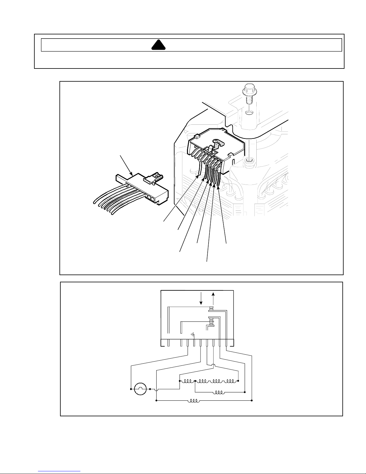
Internal Motor Diagram and Schematic
s
!
WARNING
To avoid risk of electrical shock, personal injury, or death, disconnect power to washer before servicing, unless
testing requires it.
Wire harness
connection
block
White
R
P
R
B
W
U
B
Y
R
Overload
protector
Brown
Blue
W
w
o
r
B
l
e
Y
W
R
te
i
h
Yellow
Aux.
Motor Assembly
(one speed motor)
Yellow
START
G
BR
n
w
o
l
RUN
Y
BU
4P M
Red
B
R
e
d
l
u
e
10
16022937 Rev. 0
©2005 Maytag Service
Internal Motor Diagram and Schematic
T
!
WARNING
To avoid risk of electrical shock, personal injury, or death, disconnect power to washer before servicing, unless
testing requires it.
Wire harness
connection
block
R
W
P
R
B
U
B
Y
White
W
Yellow
Brown
Blue
R
te
i
h
B
P
w
o
r
Yellow
G
W
n
o
l
l
e
Y
Violet
STAR
BU
BR
w
4P M
RUN
Y
6P M
Red
V
B
l
u
R
e
d
i
o
l
e
t
e
©2005 Maytag Services 16022937 Rev. 0
Overload
protector
Aux.
Motor Assembly
(two speed motor)
11

Internal Motor Diagram and Schematic
s
!
WARNING
To avoid risk of electrical shock, personal injury, or death, disconnect power to washer before servicing, unless
testing requires it.
G
W
W-BK
BU
Y
White
OR
R
BK
V
Black
R
Yellow
White/Black
START
RUN
OR
G
W
WHITE
Y
YEL
W-BK
BU
BLU
W
H
T
4P MAIN
-BLK
Motor Assembly
(three speed motor)
Blue
BK
V
B
L
K
PROT
AUX
W/OR
PLUG
W/V
8P MAIN
6P MAIN
12
16022937 Rev. 0
©2005 Maytag Service

Automatic Temperature Control
!
To avoid risk of electrical shock, personal injury, or death, disconnect power to washer before servicing, unless
testing requires it.
ETC Control Operation
ETC Cold Fill- The ETC cold fill toggles the water valve hot supply on and off to maintain a cold wash temperature
of approximately 55 to 65° F. If the cold water output is above 55°F, the ETC Control Board will not
energize. As a result ETC will not affect the water fill process in the cold wash setting.
ETC Warm Fill- The ETC warm fill toggles the water valve hot supply on and off to maintain a warm wash
temperature of approximately 69° to 79° F. If the cold water output is above 69° F, the ETC Control
Board will not energize. As a result ETC will not affect the water fill process in the warm wash
setting.
ETC Hot Fill- The ETC hot fill toggles the water valve hot supply on and off to maintain a hot wash temperature of
approximately 81° to 91° F. If the cold water output is above 81° F, the ETC Control Board will not energize. As a
result ETC will not affect the water fill process in the warm wash setting.
ETC Control Diagnosis
The cold water valve is energized continually during fill. 120 VAC is supplied from pin #1 on the ATC bo ard to
energize the hot water valve as needed to achieve the desired temperature. In most instances, the hot water valve
will only be energized for a short time. 120 VAC is supplied to the ATC board at pins 8 and 9. A thermistor is used to
sense the water temperature entering the tub. The thermistor resistance is approximately 1100 ohms at room
temperature (70 °F). The ohm reading will increases as the thermistor temperature rises. Because the resistance is
higher, the voltage is lower coming out of the thermistor and into pin #2 on the ETC board. The ETC board monitors
pin #2 to determine the correct water temperature.
The water temperature switch input setting is monitored at the ETC board and can be diagnosed by checking the
following:
Hot Selected – 0 VAC at pins 3 to neutral and 4 to neutral.
Warm Selected – 120 VAC at pin #4, 0 VAC at pin #3.
Cold Selected – 120 VAC at pins #3 and #4.
©2005 Maytag Services 16022937 Rev. 0
WARNING
Pin #1
13

Automatic Temperature Control
s
!
To avoid risk of electrical shock, personal injury, or death, disconnect power to washer before servicing, unless
testing requires it.
If the water temperature during an unregulated
Cold/Cold or Hot/Cold fill is not correct, the problem is
with something other than the ETC board.
Below is the electrical circuit with Warm/Warm regulated temperature selected. Trace the circuit and active
components to diagnose ETC related issues.
ATC Control Operation
ATC Cold Fill- The ATC cold fill toggles from cold to warm in order to boost
cold wash water temp to approximately 75 degrees minimum.
ATC Warm Fill- The ATC warm fill toggles from hot to warm in order to boost
the warm water temperature to approximately 95 degrees minimum.
*NOTE: ATC does not function for rinse.
WARNING
14
16022937 Rev. 0
©2005 Maytag Service

Automatic Temperature Control
A
!
To avoid risk of electrical shock, personal injury, or death, disconnect power to washer before servicing, unless
testing requires it.
To properly test ATC thermostats follow the steps below:
*IMPORTANT: To protect meter all continuity checks must be made on the connector end going to thermostats.
Step 1. Disconnect 4-wire plug connector located in blackguard coming from water flume thermostats.
Step 2. Set water temperature selection for cold water fill and allow washer to fill for 2 minutes. Confirm water
Step 3. Set water temperature selection for hot water fill and allow washer to fill for 2 minutes. Confirm water
Step 4. If results of continuity checks do not correspond to table and all wiring is correct, replace ATC flum e
TC Connector
Terminals
1RED
VIOLET
YELLOW
BLUE 4
temperature entering washer is < 60 degrees and make continuity checks per ta ble.
temperature entering washer is > 110 degrees and make continuity checks per table.
thermostat.
2
3
Water temperature
<60 degrees
<60 degrees
>110 degrees
>110 degrees
Screw is located under Control
Panel on the Cabinet Top
WARNING
Wire Color
RD to VT
BU to YL
RD to VT
BU to YL
Circuit
open
closed
closed
open
©2005 Maytag Services 16022937 Rev. 0
15

Troubleshooting Procedures
!
To avoid risk of electrical shock, personal injury, or death, disconnect power to washer before servicing, unless
testing requires it.
Leaking
• Make sure supply hose connections are not
leaking. Check for rubber gasket damage due to
over tightening.
• Make sure end of drain hose is correctly inserted
and secured to drain facility.
• Avoid overloading.
• Check internal hose connections.
• Check for overflowing standpipe.
• Check pump out speed.
• Check tub cover. Remove, reposition and reinstall
the tub cover seal.
• Check water mixing valve for cracks or hose
connection leak.
• Check tub seal for leak.
• Check for water inlet flume damage.
Will Not Drain
• Check for restricted drain system.
• Check for broken impeller on pump.
No Water Fill
• Check to make sure water supply turned on fully.
• Normal water level. See chart.
Model
Home Energystar model
• Check for kinks in inlet hoses.
• Check for clogged inlet screens.
• Visually check hot and cold separately at
dispenser for proper flows.
• If complaint is a high-pitched noise during fill then
disconnect supply hoses and clean screens.
• Is 120VAC present at outlet.
• Check for blown fuse or tripped breaker.
• Check lid switch assembly.
• Check Pressure Switch for continuity between
terminals. (See component testing)
• Check timer contacts.
• Check for continuity on water valve solenoid.
(See component testing)
Vibration
• Weak floors can cause vibration and walking.
• Legs level and secure.
• Be sure rubber feet are installed on leveling legs.
• Check that the leveling leg lock nuts are
tightened.
• Remove front panel and check that the
suspension springs are attached to the base and
outer tub.
• Check agitator for correct installation.
4.5 ± 1
Low
High
13 ± 1
WARNING
• Check transmission for spin bearing noise.
• Check belt.
• Check pump pulley and bearing.
• Check motor pulley and bearings.
Will Not Start
• Plug cord into live electrical outlet
• Check fuse or reset circuit breaker.
• Close lid.
• Check to see if the washer in a pause or soak
period in the cycle. Wait briefly and it may start.
• Check for restricted drain system.
• Check cam chart per cycle.
Wrong Water Temperature
• Are both faucets on fully?
• Make sure temperature selection is correct.
• Make sure hoses are connected to correct
faucets and inlet connections. Flush water line
before filling washer.
• Check the water heater. It should be set to
deliver a minimum 120°F (49°C) hot water at the
tap. Also check water heater capacity and
recovery rate.
• If the water heater is located a long distance from
washer, water line may need to be purged prior to
starting wash cycle.
• Disconnect inlet hoses and clean screens.
• Check ETC operation.
Will Not Spin
• Check for unbalanced load.
• Check for broken or slipping belt.
• Does the house drain system accept water from
machine?
• Check for blocked drain hose.
• Check for binding tub seal.
• Check for partial engagement of brake assembly.
• Check for obstruction between tubs.
• Check for broken impeller on pump.
Clothes Wet After Spin
• Check for unbalanced load.
• Check for slipping belt.
• Check for partial engagement of brake assembly.
• Check pump for obstruction.
• Check for drain hose restriction.
• Check for drain plumbing restriction.
Tub Full of Water
• Check for drain hose restriction.
• Che
• Check pump for obstruction or proper operation.
ck for drain plumbing restriction.
16
16022937 Rev. 0
©2005 Maytag Services

Troubleshooting Procedures
!
To avoid risk of electrical shock, personal injury, or death, disconnect power to washer before servicing, unless
testing requires it.
• Check for proper polarity of motor against timer
sequence chart.
• Check for loose or slipping belt.
Water fill does not stop at proper level
• Failed pressure switch.
• Air leak in pressure hose. Replace pressure hose.
• Water in pressure hose. Blow air through hose to
remove water.
• Broken, weak, or missing mixing valve armature
spring.
• Sediment on or under mixing valve diaphragm,
failed diaphragm, or armature binding in armature
guide. Replace mixing valve.
• A siphoning action started in washer will cause
water to be siphoned from washer during cycle.
Caused by drain hose being lower than washer
cabinet top. Install No. 526P3 Siphon Break Kit.
Provide an air gap around drain hose and drain
receptacle. Install No. 36878 Standpipe Adapter.
• Failed electronic control.
• Broken, loose, shorted or incorrect wiring.
Timer does not advance
• Timer is designed to pause during fill periods.
Some cycles have pause (delicate cycle).
• Loading door is open.
• Washer will not fill. Timer pauses until pressure
switch is satisfied.
• Verify washer is not siphoning during rinse cycle.
Install No. 526P3 Siphon Break Kit.
• Failed timer.
• Broken, loose, shorted, or incorrect wiring.
Motor does not operate
• Power cord not plugged in, blown fuse or tripped
circuit breaker at circuit panel.
• Loading door not closed or failed switch.
• Motor overload protector has cycled. Wait two to
three minutes for overload protector to reset.
• Binding in upper or lower motor bearings.
• Motor is dead, electrical power is present. Test
motor switch and windings.
• Motor start functions fail or motor only hums. Test
motor start switch and start windings.
• Timer improperly set.
• Failed timer.
Washer smokes, overheats, and cycles on
overload protector or switch actuator kicks in and
out.
• Belt is tacky and does not allow proper slipping.
• Belt tension is too tight and does not allow proper
slipping.
©2005 Maytag Services 16022937 Rev. 0
WARNING
• Motor start functions fail.
• Bind in water pump.
• Brake pads are binding.
• Brake, transmission or motor have locked up and
will not turn.
• Failed timer.
• Incorrect voltage. Contact local utility company, or
have a qualified electrician check power supply
voltage.
No agitation
• Failed timer. Timer is designed to pause (SOAK)
during DELICATE cycle.
• Failed pressure switch.
• Loose or broken drive belt.
• Failed transmission assembly.
• Sheared motor pulley roll pin.
• Motor overl
three minutes for overload protector to reset.
• Bind in water pump.
• Loading door not closed or failed switch.
• Failed timer.
• Broken, loose, shorted or incorrect wiring.
Constant agitation
• Failed timer.
• Shorted or incorrect wiring.
Constant spin
• Washtub does not stop spinning within seven
seconds after loading door is open. Replace
brake pads. Tighten Helix Bolt if loose.
• Excessive wear on brake pads, or missing brake
pads.
• Failed timer.
• Failed electronic control.
• Broken, loose, shorted or incorrect wiring.
Washer stops in middle of cycle or quits after a
couple loads ⎯ intermittent
• Belt is tacky and does not allow proper slipping.
• Belt tension is too tight and does not allow proper
slipping. Verify idler spring is properly connected.
Verify proper belt and pulley are installed.
• Motor overload protector has cycled. Wait two to
three minutes for overload protector to reset.
• Brake, transmission or motor have locked up and
will not turn.
• Motor switch functions fail.
• Failed timer.
• Broken, loose, shorted or incorrect wiring.
oad protector has cycled. Wait two to
17

Troubleshooting Procedures
!
To avoid risk of electrical shock, personal injury, or death, disconnect power to washer before servicing, unless
testing requires it.
Washer locks-up or binding
• Excessive drive belt tension. Replace drive belt
and/or idler spring.
• Bind in upper or lower bearing. Replace bearing.
• Broken, loose, shorted or incorrect wiring.
WARNING
• Bind in water pump.
• Bind in transmission.
• Brake pads are binding.
• Incorrect voltage.
18
16022937 Rev. 0
©2005 Maytag Services

Disassembly Procedures
!
!
WARNING
To avoid risk of electrical shock, personal injury, or
death, disconnect power to unit before servicing.
NOTE: When reference is made to directions (right or
left) in this manual, it is from operator’s position
facing front of washer.
NOTE: To avoid damaging or scratching the surface a
soft cloth should be placed over the top of the
unit.
Control Hood Assembly
1. Remove screws securing control hood assembly to
control hood rear panel.
Hood
attaching
screws
2. Rotate hood assembly forward.
Pivot
hood
forward
Timer
1. Loosen control hood assembly, see “Control Hood
Assembly” procedure steps 1 and 2.
2. Remove timer knob from timer shaft by pulling black
plastic tab located on the back of timer outward to
release knob, then remove timer knob skirt.
NOTE: Slide a soft cloth under the knob skirt, wrapping
the entire skirt and pull gently away from the
control panel.
EMERSON
R
R
R
C
R
Knob
shaft
3. Remove screws securing timer to control hood
mounting plate.
4. Disconnect wire harness terminal plug from timer by
lifting locking tab and pulling terminal plug away from
timer.
5. Lift plastic tab marked 1 located above securing
screw and sliding timer to the side releasing tabs
securing timer to control hood mounting plate.
6. Reverse procedure to reassemble.
NOTE: To avoid an open circuit, DO NOT pull on
terminal block wires when removing blocks from
timer as this could damage wires or terminal
crimping.
Before attaching wire harness terminal blocks to timer,
verify all male terminals on timer are straight and are
capable of accepting terminals from wire harness
terminal blocks.
Black
plastic
tab
Securing
screw
Plastic tab
marked 1
3. Remove bottom of control hood from clips located on
cabinet top.
4. Disconnect wires from components and carefully
remove components from control hood assembly.
5. Reverse procedure to reassemble.
NOTE: See appropriate wiring diagram when rewiring
components.
Control Hood End Panels
• Remove screws securing end panels to control
mounting plate.
©2005 Maytag Services 16022937 Rev. 0 19
NOTE: When installing timer, verify timer is installed
correctly and is securely mounted to control
mounting plate.
CAUTION
To avoid risk of timer damage, do not allow timer to be
struck on the corners, edges of frame, or on timer
shaft.

Disassembly Procedures
!
WARNING
To avoid risk of electrical shock, personal injury, or
death, disconnect power to unit before servicing.
Temperature and Speed Switch
1. Loosen control hood assembly, see “Control Hood
Assembly” procedure steps 1 and 2.
2. Slide a soft cloth under the knob, wrapping the entire
knob and pull gently away from the control panel.
3. Disconnect wires from switch terminals.
4. From the front, press inward on black plastic tabs
next to the switch shaft and rotate switch to release
switch from control hood mounting plate.
5. Reverse procedure to reassemble.
NOTE: See appropriate wiring diagram when rewiring
components.
Pressure Switch
Top
cover
Screw
End panel
(left side)
Screw
Control
knob
1. Loosen control hood assembly, see “Control Hood
Assembly” procedure steps 1 and 2.
2. Disconnect wires and plastic hose from pressure
switch.
3. Remove screws securing pressure switch to control
hood mounting plate.
4. Reverse procedure to reassemble.
NOTE: See appropriate wiring diagram when rewiring
components.
NOTE: Before connecting hose to pressure switch, blow
air through pressure hose to remove any
condensation that may have accumulated in the
hose.
Screws
Temperature
switch
Pressure
switch
Screw
Speed
switch
Timer
Rocker
switch
Timer
Timer
knob
Graphic
panel
20 16022937 Rev. 0 ©2005 Maytag Services
knob
skirt
Ground
clip
Control
mounting
plate
Screw
Hold-down
clip
Typical Control Panel Assembly
Control hood
rear panel
Screw
Screw
End panel
(right side)
Screw

Disassembly Procedures
!
WARNING
To avoid risk of electrical shock, personal injury, or
death, disconnect power to unit before servicing.
Rocker Switch
1. Loosen control hood assembly, see “Control Hood
Assembly” procedure steps 1 and 2.
2. Disconnect wire terminals from switch.
3. Squeeze plastic tabs located on top and bottom of
switch and push switch out through the front of
control panel.
4. Reverse procedure to reassemble.
Graphic Panel
1. Remove all knobs from switches.
2. Loosen control hood assembly, see “Control Hood
Assembly” procedure steps 1 and 2.
3. Disconnect wires from components and carefully
remove components from control hood assembly,
see component removal procedure listed earlier.
4. Remove screws securing top cover to control
mounting plate and remove top cover.
5. Remove screws securing end panels (each side) and
remove end panels.
6. Remove grounding clip secured to metal tab on
graphic panel.
7. Bend tabs on graphic panel (located inside of control
hood) straight out towards the rear.
8. Remove graphic panel from front of control mounting
plate.
9. Reverse procedure to reassemble.
NOTE: See appropriate wiring diagram when rewiring
components.
Loading Door
1. Open loading door.
2. Remove screws securing left hinge to door and
remove hinge.
Loading
door
Hinge
attaching
screws
Hinge
attaching
screws
Hinge
(right side)
Hinge
(left side)
3. Raise loading door to a vertical position, disengage
loading door from loading door clip by swing left side
of door toward front of washer.
Loading
door
©2005 Maytag Services 16022937 Rev. 0 21
4. Rotate loading door so door is upside down.

Disassembly Procedures
!
WARNING
Loading
door
5. Maneuver loading door from washer cabinet top.
Loading
door
To avoid risk of electrical shock, personal injury, or
death, disconnect power to unit before servicing.
Top Cover
1. Remove Service Access Panel and Front Panel.
2. Remove 2 screws securing Top Cover to Cabinet.
3. Lift Top Cover.
6. Remove screws securing right hinge and remove
loading door.
7. Reverse procedure to reassemble.
Service Access Panel/Front Panel
1. Remove bottom screws in Access Panel.
2. Remove lower screws in Front Panel.
22 16022937 Rev. 0 ©2005 Maytag Services

Disassembly Procedures
!
WARNING
To avoid risk of electrical shock, personal injury, or
death, disconnect power to unit before servicing.
Agitator
1. Open loading door.
2. Remove fabric softener dispenser by unsnapping from
agitator. Remove agitator by one of two ways.
a. (Auger style agitators) Loosen bolt in
agitator and remove by sliding straight
up output shaft of transmission.
b. (Flex vane agitators) Remove flex vane
agitator by placing hands under agitator
lip and pull upward. If agitator is difficult
to remove, use two agitator removal
hooks, No. 254PRP under bottom edge
of agitator. Remove drive bell by pulling
upward. If drive bell is difficult to remove,
use agitator hooks.
a.
a.
Agitator
b.
NOTE: Hooks must be positioned 180° from each other,
and must be placed under base of agitator near
agitator vane for greater stability. If hooks are
placed between the vane area, agitator damage
may occur.
3. Using a rocking motion (side-to-side) carefully lift
agitator up off drive bell.
4. To reassemble place agitator on top of drive bell.
Slowly rotate agitator until fingers on underside of
agitator line up with large slots on drive bell.
5. A sharp blow on top of agitator, with the palm of your
hand, will force agitator down onto drive bell, allowing
fingers on underside of agitator to lock under bottom
edge of drive bell.
NOTE: Do not push agitator onto drive bell any further
than necessary.
hooks
Door Switch
1. Remove front panel, see “Front Panel” procedure.
2. Remove screws securing cabinet top.
3. Tape loading door closed and lift cabinet top to a
vertical position by hinging it on the rear hinges.
NOTE: Cabinet top is self supporting, a small chain may
be used for additional support.
4. Disconnect wires from door switch.
5. Remove screw securing door switch assembly to
underside of cabinet top.
NOTE: See appropriate wiring diagram when rewiring
components.
6. Remove screws securing switch to switch holder.
7. Remove switch from switch holder.
8. Reverse procedure to reassemble.
©2005 Maytag Services 16022937 Rev. 0 23
Drive Bell and Seal Assembly Style Units
NOTE: If water is present in washtub, remove water
before attempting to remove drive bell.
1. Remove agitator, see “Agitator” procedure.
2. Remove plug and 7/16" bolt from top of drive bell.

Disassembly Procedures
!
WARNING
To avoid risk of electrical shock, personal injury, or
death, disconnect power to unit before servicing.
3. Using care pry drive bell upward off transmission
shaft.
4. Remove old seal from hub assembly by:
a. Placing a flat bladed screwdriver between bottom
edge of seal and hub.
b. Using washtub bolts as a pry area, pop off lower
seal bead.
c. Grasping bottom of seal and pulling straight up
freeing upper seal bead.
Hex
nut
Hub
assembly
Hub
shoulder
5. Clean all foreign material from seal mounting area of
hub assembly, bronze bearing and washer.
6. Lubricate new seal with liquid soap or soapy water to
aid in assembly of seal onto hub.
7. Apply a small amount of supplied grease,
No. 36765P, to inside sealing lips of seal.
Apply grease to
inside sealing lips
Hub
assembly
NOTE: DO NOT allow any lubricants to come in contact
with outside surface of seal.
8. Apply remainder of supplied grease, No. 36765P, to
exposed surface of washer between transmission
output shaft and seal.
9. Place new drive bell seal onto hub and push into
position using large end of No. 293P4 Seal Tool.
Transmission
output shaft
Washer
Bronze
bearing
Transmission
output shaft
Seal
NOTE: Using a small pocket mirror, check entire
circumference of bottom seal flange to verify seal
is pressed down against shoulder on hub; there
should be no gap!
10.Turn No. 293P4 Seal Tool upside-down and place the
small end over transmission output shaft and onto the
seal.
11. Push down on tool with a quick motion until it
bottoms out and the top of seal is fully seated.
293P4
Seal tool
Hub
assembly
293P4
Seal tool
Hub
assembly
Hub
shoulder
Bottom
seal flange
Top of
seal
Apply
36765P
grease
Installing Drive Bell
1. Position new drive bell over transmission output shaft.
Rotate drive bell until splines in drive bell line up with
splines on transmission output shaft.
2. Screw 7/16" bolt into transmission output shaft until it
bottoms out.
3. Using a wrench or socket, tighten bolt CLOCKWISE
to force drive bell down onto transmission shaft until
drive bell bottoms out on shaft.
NOTE: Tighten new shoulder screw between 60 to 80
inch-pounds.
4. Place new plug over hole in drive bell and firmly press
into place using the palm of your hand.
NOTE: It may be necessary to insert the end of a paper
clip or thin blade screwdriver along side of plug
as it is pressed into drive bell to release
entrapped air.
24 16022937 Rev. 0 ©2005 Maytag Services

Disassembly Procedures
!
WARNING
To avoid risk of electrical shock, personal injury, or
death, disconnect power to unit before servicing.
NOTE: When fully seated plug should not extend above
drive bell more than 1/8 inch (3.2 mm).
5. Place agitator on top of drive bell. Slowly rotate
agitator until fingers on underside of agitator line up
with large slots on drive bell.
6. A sharp blow on top of agitator, with the palm of your
hand, will force agitator down onto drive bell, allowing
fingers on underside of agitator to lock under bottom
edge of drive bell.
NOTE: Do not push agitator onto drive bell any further
than necessary.
Counter Balance Spring
The counter balance, which offsets the weight of the
motor, was replaced with a spring. In addition to this the
6 tall tub springs were replaced with 6 new springs. The
new springs are 11" long and have 26 coils in the body.
The old springs were 11.75" long and have 18 coils in the
body. The counter balance and new tub springs must be
used together in non-counter weight models. The new
counter weight spring will attach to the milk stool leg and
base as shown below. A loop was added to the spring, to
aid in installation and removal.
Triple Lip/Bearing Style Units
1. Remove agitator, see “Agitator” procedure.
2. Unsnap and remove Outer Tub Cover.
3. Remove O-Ring from transmission output shaft.
4. Use spanner wrench (35-2968) and seal tool
(22002898) to remove seal nut.
5. Remove inner tub bolts and inner tub.
The 2 rear springs are mouted upsidedown to avoid the
possability of the springs rubbing togrther.
Service Loop
©2005 Maytag Services 16022937 Rev. 0 25
Tub Spring
27001026
Counter Balance
27001025
6. Remove lint filter.
7. Remove washtub hub with Maytag spanner tool
22038313. Turn spanner counterclockwise to remove.
It may be necessary to lock transmission from
turning. Attach clamp or Visegrip® tool to
transmission only as shown. Transmission will stop
rotating when clamp contacts tub support.

Disassembly Procedures
!
WARNING
To avoid risk of electrical shock, personal injury, or
death, disconnect power to unit before servicing.
10.Remove drive belt from transmission pulley.
11. Remove pressure hose from pressure bulb on outer
tub.
12.Lift outer tub and transmission assembly out of
washer cabinet. Turn outer tub and transmission
assembly upside-down on protective padding.
13.Remove screws holding leg support to outer tub.
Separate transmission assembly from outer tub.
8. Disconnect tub drain hose from outer tub.
9. Remove bolts from motor assembly and drop motor
down to base. Disconnect wire harness from motor
tap.
14.Remove seal and bearing using the brake removal tool
12002012 with included 3" PVC end cap.
15.Coat new triple lip seal with petroleum jelly.
16.Apply center seal grease (056016) to Seal Nut before
installing.
26 16022937 Rev. 0 ©2005 Maytag Services
Triple Lip Seal (petroleum jelly.)

Disassembly Procedures
!
WARNING
Seal Nut (seal grease 056016.)
17.Install new bearing using Brake/Bearing tool
12002012, large washers and PVC end cap.
Important: Use large washers to prevent damage
to bearing.
To avoid risk of electrical shock, personal injury, or
death, disconnect power to unit before servicing.
5. Disconnect wire harness from motor switch by
pressing down on locking tab on top of connection
block and at the same time, pull connection block
away from motor switch.
Switch attaching screws
Locking
tab
Motor
switch
Belt
18.Reassemble washer.
Connecting
block
6. Remove bolts securing motor and mounting bracket to
lower outer tub flange and to weldment assembly.
Motor mounting
attaching screws
Idler
spring
Motor and Mounting Bracket
1. Remove service access panel, see “Service Access
Panel” procedure.
NOTE: There will always be some water that will remain
in outer tub, before removing hoses from pump,
hoses must be pinched off or drained to prevent
water spillage.
2. Loosen hose clamps and remove hoses from pump
assembly.
3. Unhook idler spring from clip on front of the motor
mounting bracket.
NOTE: Use care when releasing idler lever tension. If
idler spring is overstretched, washer operation
will be affected.
4. Reach in and around left side of motor and remove
belt off large drive pulley.
©2005 Maytag Services 16022937 Rev. 0 27
7. Lift complete assembly out of washer.
NOTE: Lay motor on its side. Observe belt configuration
around rear pump leg. Belt MUST encircle rear
pump leg when reassembling.
8. Reverse procedure to reassemble.
Pump and Belt Removal
1. Remove motor, see “Motor and Mounting Bracket”
procedure.
2. Remove screws securing pump assembly to motor.
Pump
hoses

Disassembly Procedures
!
WARNING
To avoid risk of electrical shock, personal injury, or
death, disconnect power to unit before servicing.
Reassembly of Pump and Belt
NOTE: Install pump and belt together. Drive belt MUST
be replaced with belt No. 40053602 for one and
two speed models; or 40053601 for some two
speed models and three speed models (special
clutch-type belt) for proper washer operation.
Refer to Parts Manual for proper belt part
number.
1. Remove any corrosion or foreign material from motor
shaft.
2. Apply a thin film of No. 03637P lubricant to the end
and sides of motor shaft.
NOTE: This lubricant helps keep moisture out of the hub
area and prevents corrosion.
3. Align belt on motor pulley and tension pulley as
illustrated.
Pump
mounting screws
Rear
Pump
assembly
Pump
legs
Motor
embosses
Motor
assembly
pump leg
(Must be located
between belt when
installing pump
assembly.)
Motor shaft
(Clean shaft and apply
a thin film of lubricant
No. 03637P.)
Motor
emboss
Motor Disassembly
1. Remove nuts, steel washers, spacers and rubber
mounts securing motor to mounting bracket.
Motor
shield
Motor
switch
Motor
pully
Motor
mount
post
Motor
mount
Screw
Washer
Motor
mount
Motor
mount post
2. Lift motor off mounting bracket and remove remaining
rubber mounts and steel washers from motor
mounting studs.
NOTE: When installing motor on mounting bracket,
position motor with switch facing toward left side
of mounting bracket.
NOTE: When assembling motor to motor bracket, it is
extremely important to make sure the motor is
centered on isolator pads and all fasteners are
evenly torqued.
Screw
Motor
assembly
Roll
pin
Motor
mounting
bracket
Locknut
Screw
Locknut
4. Align pump impeller hub with motor shaft. Verify belt
encircles rear pump leg. Slide pump onto motor shaft
until legs touch the embosses on the motor housing
before securing.
NOTE: Tighten screws to 35 inch-pounds maximum. DO
NOT overtighten screws!
5. Install motor and pump assembly into washer, see
“Motor and Mounting Bracket” procedure.
NOTE: After installing motor and pump assembly in the
washer and all hoses have been secured, along
with reconnecting idler spring. Add at least one
quart of water to washtub to lubricate pump
seals. Running a pump without water will
damage the seals.
28 16022937 Rev. 0 ©2005 Maytag Services
Idler Lever and Pulley
1. Remove motor, see “Motor and Mounting Bracket”
procedure.
Idler spring
Motor shaft
(Clean shaft and apply
a thin film of lubricant
No. 03637P.)
Motor
assembly

Disassembly Procedures
!
!
WARNING
To avoid risk of electrical shock, personal injury, or
death, disconnect power to unit before servicing.
NOTE: Lay motor on its side. Observe belt configuration
around rear pump leg. Belt MUST encircle rear
pump leg when reassembling.
2. Remove nut, washer, and bolt securing idler lever and
pulley to motor mounting bracket.
3. Apply a light film of No. 03637P Lubricant to area of
idler lever that makes contact with motor mounting
bracket.
NOTE: DO NOT OVER LUBRICATE! Excess lubricant
can be thrown into pivot dome area during normal
washer operation. Any lubricant on the pivot
dome, base or friction ring will affect washer
operation.
4. Reverse procedure to reassemble.
Motor Drive Pulley
1. Remove idler lever and pulley steps 1–3, see “Idler
Lever and Pulley” procedure.
2. Lay motor assembly on its side.
NOTE: To remove pulley, support motor shaft (to prevent
bending shaft) and drive out pulley roll pin.
3. Reverse procedure to reassemble.
Motor Switch
1. Remove front panel, see “Front Panel” procedure.
2. Remove screws securing motor shield to motor.
3. Disconnect wire harness from motor switch. Press
down on locking tab connection block and at the
same time, pull connection block away from motor
switch.
CAUTION
To avoid risk of an open circuit, DO NOT pull on
terminal block wires when removing block from motor
switch as this could damage wires or connection
crimpings. Before attaching wire harness connection
block to motor switch, verify all male terminals on
motor switch are straight and are capable of accepting
terminals from wire harness connection block.
Switch attaching
screws
Locking
tab
Connection
block
4. Remove screw securing motor switch to motor and
remove switch.
5. Disconnect internal motor leads from motor switch
terminals.
NOTE: See appropriate wiring diagram when rewiring
components.
Motor
switch
Mixing Valve
1. Disconnect water inlet hoses.
2. Remove screw securing mixing valve bracket.
3. Pull mixing valve bracket and valve out the back of
washer.
4. Disconnect quick disconnect terminals from mixing
valve solenoid terminals.
NOTE: See appropriate wiring diagram when rewiring
components.
5. Reverse procedure to reassemble.
Tub Cover and Gasket
1. There are eight tub cover hold-down tabs which snap
over the outer tub flange. Push downward on tub
cover, this will release the tension on the hold-down
tab on the tub cover. Pull out on the flap and at the
same time lift upward on cover to unsnap hold-down
tabs from outer tub flange. One by one, disengage
each of the eight hold-down tabs from outer tub flange
and remove cover.
2. Remove tub cover from outer tub and remove old
gasket from tub cover.
NOTE: When installing outer tub cover, always use a
new cover gasket.
©2005 Maytag Services 16022937 Rev. 0 29
NOTE: Clean and remove any foreign material in gasket
groove of outer tub cover and outer tub flange.

Disassembly Procedures
!
WARNING
To avoid risk of electrical shock, personal injury, or
death, disconnect power to unit before servicing.
3. Press gasket down into gasket groove of tub cover.
Avoid pressing gasket past ends of hold-down tabs.
NOTE: Care must be taken not to twist or bunch gasket
in any one area to avoid leaks after assembly.
4. Install gasket past ends of hold-down tabs to bottom
of gasket groove using semi-curled end of tub cover
gasket tool Part No. 273P4.
NOTE: Tub cover gasket tool, Part No. 273P4, is
designed to spread open hold-down tabs to
prevent tearing of gasket during installation.
5. Lower cover and press down firmly on top of
tub cover until tabs snap over edge of outer tub
flange.
6. Cross over to opposite side of tub cover and press
down firmly on top of hold-down tabs until tabs snap
over edge of outer tub flange. Continue with this
crisscross pattern, until tub cover is fully seated.
Visually check each tab area again to ensure cover is
seated.
Washtub and Balance Ring
1. Open loading door.
2. Remove agitator, see “Agitator” procedure.
3. Loosen cabinet top, see “Cabinet Top” procedure.
4. Hinge cabinet top open to gain access.
5. Loosen and remove hose clamp and fill hose from
outer tub cover.
6. Remove tub cover, see “Tub Cover and Gasket”.
7. Remove bolts and washers securing washtub to hub.
8. Lift washtub and balance ring out of outer tub.
NOTE: When removing washtub and balance ring, DO
NOT lift up on balance ring damage may occur.
Grasp top flange of washtub and remove from
outer tub.
9. Reverse procedure to reassemble.
NOTE: When installing washtub, verify lint filter is
between underside of washtub and hub.
Drive Pulley, Helix and Brake
1. Remove outer tub, see Outer Tub” procedure.
2. Remove screw, washer and helix securing drive pulley
to input shaft and transmission assembly.
NOTE: When reinstalling pulley, place a small amount of
No. 03200P Lubricant on top side of the drive
pulley that will be contacting large flat washers.
Lubricate helix ramps and bore with a small
amount of No. 03200P Lubricant.
3. Lift drive pulley up and off input shaft of transmission
assembly.
30 16022937 Rev. 0 ©2005 Maytag Services
NOTE: When reinstalling pulley, place a small amount of
No. 03200P Lubricant on top side of the drive
pulley that will be contacting large flat washers.
Lubricate helix ramps and bore with a small
amount of No. 03200P Lubricant.
DO NOT OVER LUBRICATE! Excess lubricant
can be thrown into pivot dome area during normal
washer operation. Any lubricant on pivot dome,
base or friction ring will affect washer operation.
This condition will persist until lubricant is
removed.
4. Remove bolts securing brake pads and brake
assembly to weldment assembly. Remove brake
assembly and pads off bottom of weldment assembly.
NOTE: When reinstalling brake assembly, replace all
three brake pads. DO NOT replace worn pads
only. Apply a small amount of No. 26594P
Silicone Lubricant to both sides of each brake
pad where it will contact brake assembly.
DO NOT OVER LUBRICATE! Excess lubricant
can be thrown into pivot dome area during normal
washer operation. Any lubricant on pivot dome,
base or friction ring will affect washer operation.
This condition will persist until lubricant is
removed.
5. After brake is installed, put washer through the
following check to verify brake is operating properly.
a. Turn off electrical power to washer.
b. Turn drive pulley one complete revolution in
agitation directly, then push drive pulley up against
brake.
c. Check for a .030 (.76 mm) minimum gap between
drive pulley and helix ramp surfaces.
NOTE: If gap is less than .030 (.76 mm), brake may not
stop washtub from spinning in required seven
seconds because brake will not close properly.
d. Turn on electrical power to washer and start
washer in the final spin operation.
NOTE: After installing complete tub module in washer
and all hoses have been reconnected, add at
least one quart of water to washtub to lubricate
pump seals. Running a pump without water
will ruin the seals.
After washtub has been spinning for two
minutes, normal spin speed should be
427 ± 25 RPM SLOW speed and 640 ± 25 RPM
FAST speed on one and two speed models; or
473 ± 25 RPM on SLOW speed and
710 ± 25 RPM on FAST speed on some two
speed models and all three speed models. Three
speed models never spin on the lowest speeds. If
 Loading...