

Page 1
Installation
A
B
Location
• Do not install refrigerator near oven, radiator or
other heat source. If not possible, shield refrigerator
with cabinet material.
•
Do not install where temperature falls below 55° F
(13° C) or rises above 110° F (43° C). Malfunction
may occur at this temperature.
Refrigerator is designed for indoor household
•
application only.
Measuring the Opening
When installing your refrigerator, allow
1
and
⁄2” space behind machine compartment cover
ated in the rear) for proper air circulation. If the
(loc
refrigerator is placed with the door hinge side against
a wall, you may want to allow additional space so the
door can be opened wider
Subflooring or floor coverings (i.e. carpet, tile, wood
floors, rugs) may make your opening smaller than
anticipated.
Some clearance may be gained by using the leveling
procedure under
Important: If refrigerator is to be installed into a
recess where the top of the refrigerator is completely
covered, use dimensions from floor to top of hinge c
to verify proper clearance.
Leveling.
.
1
⁄2” space at top
ap
Door and Hinge Removal
Some installations require door removal to get
refrigerator to final location.
WARNING
To avoid severe personal injury or death,
observe the following:
• Disconnect power to refrigerator before removing
doors. Connect power only after replacing doors.
• Green ground wire must be attached to top hinge
while performing door removal and replacement.
• Tape decorative panels (select models) securely
into place
To avoid property damage, observe the following:
• Protect vinyl or other flooring with cardboard, rugs
or other protective material prior to moving
refrigerator.
Do not adjust refrigerator to be any shorter than
•
1
68
⁄2” tall (minus hinge and cap). Doing so may
damage underside components.
1.
Unplug power cord from power source.
Remove toe grille (see page 4).
2.
• Open both doors 180°, or as wide as possible.
before removing door handles.
CAUTION
Transporting Your Refrigerator
• NEVER transport refrigerator on its side. If an
upright position is not possible, lay refrigerator on it
back. Allow refrigerator to sit upright for
approximately 30 minutes
assure oil returns to the compressor. Plugging
refrigerator in immediately may cause damage to
s.
internal par
• Use an appliance dolly when moving refrigerator.
A
W
AL
back–NEV
• Protect outside finish of refrigerator during transport
by wrapping cabinet in blankets or inserting padding
between the refrigerator and dolly.
• Secure refrigerator to dolly firmly with straps or
bungee cords. T
possible.
restraints may dent or damage outside finish.
3
t
S
Y
truck refrigerator from it
ER
from it
hread straps through handle
Do not over-tighten. Over-tightening
before plugging it in to
s side or
s front.
s when
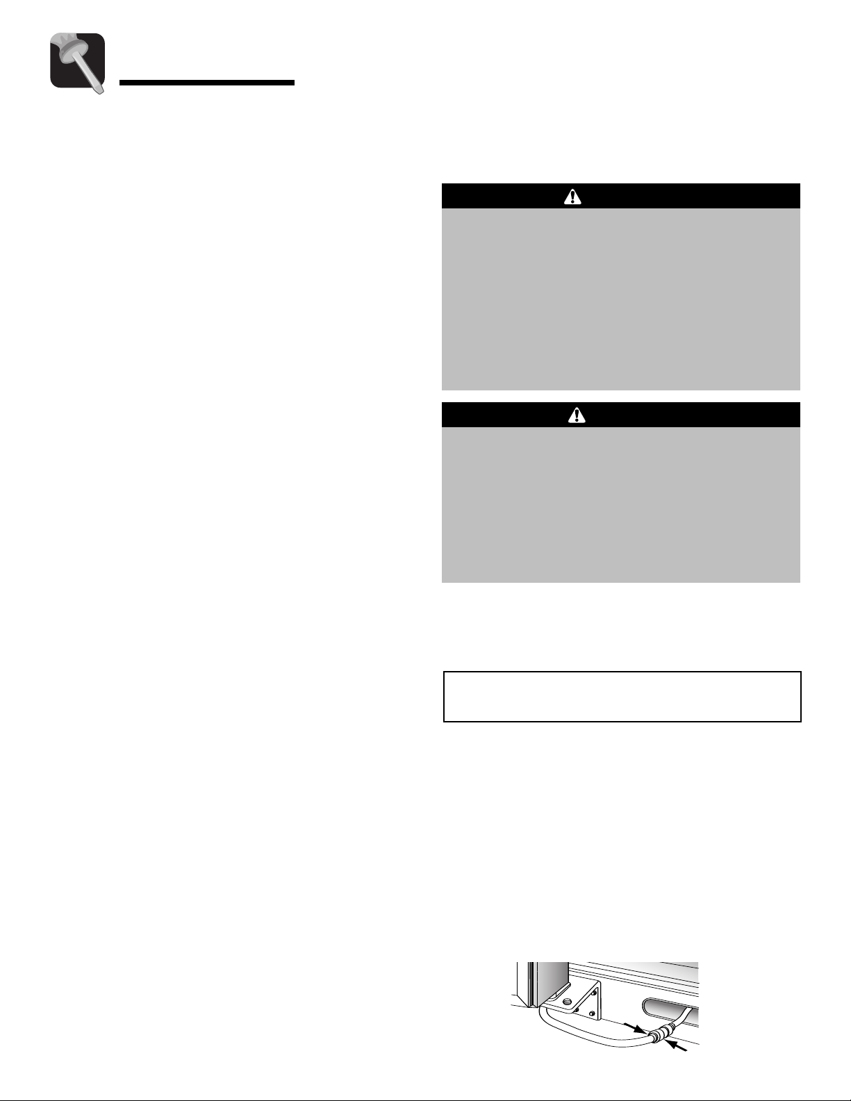
Note: For refrigerators in operation, shut off water
before removing water line from the door.
o Disconnect the Water Line:
s
T
• Push in white collar (A) and hold.
Pull the door-side tube from the connector
•
To Reconnect the Water Line:
• Firmly push tube
lines on the tube as a guide for full insertion.
• If tube end is damaged, cut off
reconnecting.
• If leaking occurs, reconnect the line.
5
⁄8” into the connector. Use
5
⁄8” before
(B).
Page 2
Installation
A
B
A
B
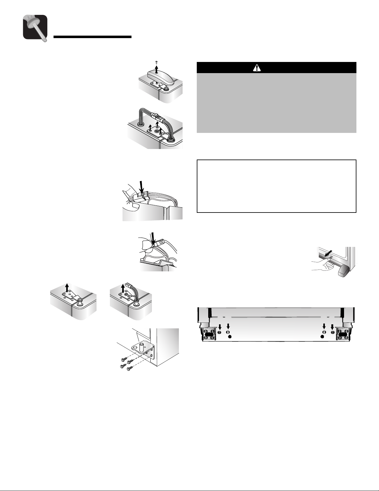
3. Close doors.
4. Remove top hinge covers by
removing Phillips screws.
5. Unscrew
top hinges.
For water dispensing
models only:
• Do not remove screw
connecting green ground
wire.
For ice and water dispensing models only:
6.
Detach main wire connector harness and red wire
harness.
• To detach main wire
harness, use a flat blade
tool or fingernail to press
junction point between two
connectors to release.
• To detach red wire harness,
pre
connector to release.
5
⁄1
” hex head screws from
6
ss tab on underside of
Leveling
CAUTION
To protect personal property and refrigerator
from damage, observe the following:
• Protect vinyl or other flooring with cardboard, rugs,
or other protective material.
•
Do not use power tools when performing leveling
procedure.
To enhance the appearance and maintain performance,
the refrigerator should be level.
Notes:
• Complete any required door reversal, panel
installation and/or a water supply connection
before leveling.
• Some models only have adjustment screws
Materials Needed:
3
•
⁄8” hex head driver
• Carpenter’s level
1. Remove toe grille.
(A).
7. Remove top hinges along with
doors.
Remove bottom hinge
8.
with a
3
⁄8” hex head driver
s
.
Replacing the Doors
• To replace the doors, follow the steps in Door and
Hinge Removal in reverse order.
Important: If water line tube end is damaged, cut off
5
⁄8” before reconnecting.
• Grasp firmly and pull outward
to unclip.
Using hex head driver
2.
screws
to lower the front of the refrigerator
3. Select models also have rear adjustment screws
(B). Using the hex head driver, turn each of these
adjustment screws (B) to raise or lower the rear of
the refrigerator
Using the c
4.
refrigerator is
back of refrigerator and that the refrigerator is level
from side to side.
5. If required, correct rocking of refrigerator by
turning rear adjustment screw
rocking corner
following:
(A) clockwise to raise and counterclockwise
.
arpenter’s level, make sure front of
1
⁄4” (6 mm) or 1⁄2 bubble higher than
. If doors are uneven, do the
, turn front adjustment
.
clockwise to raise
Cont.
4
Page 3

Installation
• Determine which
door needs to be
raised.
• Turn front roller
adjustment screw
(A) clockwise to
raise front corner of
door.
• If one refrigerator door has reached the limit of
its adjustment range and doors are still not level,
raise or lower the opposite door by turning roller
adjustment screw
• Check with level to verify
proper door closure.
If refrigerator is aligned and stable, replace toe
•
grille.
• Align the toe grille mounting clips with the lower
cabinet slot
• Push the toe grille firmly until it snaps into place.
s.
clockwise or counterclockwise.
1
⁄4” tilt to the back for
Connecting the Water Supply
(select models)
WARNING
To reduce the risk of injury or death, f
basic precautions, including the following:
• Read all instructions before installing ice maker.
• Do not attempt installation if instructions are not
understood or if they are beyond personal skill
level.
Observe all local codes and ordinances.
•
• Do not service ice maker unless specifically
recommended in Use & Care Guide or published
user-repair instructions.
• Disconnect power to refrigerator before installing
ice maker
• Water damage due to an improper water
connection may c
up spills or leakage immediately!
.
ause mold/mildew growth. Clean
ollow
CAUTION
To avoid property damage or possible injury,
follow basic precautions, including the
following:
• Consult a plumber to connect
tubing
compliance with local codes and ordinances.
• Confirm water pressure to water valve is between
35 and 100 pounds per square inch, 20 pounds
per square inch without filter.
•
Do not use a self-piercing, or
Both reduce water flow and can become clogged
over time, and may cause leaks if repair is
attempted.
• Tighten nuts by hand to prevent cross threading.
Finish tightening nuts with pliers and wrenches.
Do not over-tighten.
• Wait two to three hours before placing refrigerator
into final position to check and correct any water
leaks. Recheck for leaks after 24 hours.
• Verify the copper tubing under the sleeve is
smooth and free from defects.
old sleeve.
Materials Needed:
1
•
⁄4” outer diameter flexible copper tubing
• Shut-off valve (require
water supply line before valve att
• Adjustable wrench (2)
1
•
⁄4” hex nut driver
to household plumbing to assure
s a
1
⁄4” O.D. copper
3
⁄16” saddle valve.
Do not reuse an
1
⁄4” hole to be drilled into
achment)
Notes:
• Use copper tubing only for installation. Plastic is
less durable and can cause damage.
• Add 8’ to tubing length needed to reach water
supply for creation of service loop.
1. Create service loop with
copper tubing (minimum 2’
diameter). Avoid kinks in the
copper tubing when
bending the service loop.
not use plastic tubing.
Do
2’ diameter
minimum
Remove plastic c
2.
inlet port.
5
ap from water valve
Page 4

Installation
3. Place brass nut (A) and sleeve (B)
on copper tube end as illustrated.
Reminder: Do not use an old
sleeve. The nut and sleeve are
provided in the Use and Care
packet.
4. Place end of copper tubing into
water valve inlet port. Shape
tubing slightly.
that tubing feeds straight into inlet
port.
5. Slide brass nut over sleeve and
screw nut into inlet port.
Place adjustable wrench on nut
(1) att
and maintain position.
Using second adjustable wrench
turn the lower nut
counterclockwise and fully
tighten while holding the upper
nut in place.
ached to plastic waterline
Do not kink – so
(2)
Plastic Handle with Extensions
Attach Extensions to Handle:
1. Align handle and extension as shown.
B
A
B
A
1
2
2. Place extension in handle opening.
3. Apply slight pressure
to both sides of the
extension piece.
4. Slide extension until it
stops on inside edge
of handle.
To Install:
1. The handles are to be oriented as shown.
2. Align door handle with the door studs.
3. Ensure the large hole in the mounting clip is
positioned
down on both ends of the handle.
Important: Do not over-tighten. Cross threading
may occur
6. Pull on tubing to confirm
connection is secure.
Connect tubing to frame
with water tubing clamp
and turn on water supply.
Check for leaks and correct
if nece
observe the water supply
connection for two to three
hours prior to moving the
refrigerator to its permanent
location.
7. Monitor water connection for 24 hours. Correct
leaks, if nece
.
ary. Continue to
ss
.
ary
ss
(C)
Handle Installation
If not installed, the handle is located in the interior of
the fre
refrigerator. Remove and discard handle packaging
and tape.
sh food section or attached to the back of your
C
Door
Stud
4. Rotate the handle so that the
handle is flat against the door
5. Grasp the handle firmly and slide
down.
.
Handle de
Please reference the appropriate instructions for your
model.
sign varie
s from refrigerator to refrigerator.
Cont.
6
Page 5

Installation
To Remove:
1. Grasp the lower part of the handle firmly,
slide up, lift and remove from the
surface.
Wide-by-Side™ Handles
Materials Needed:
• Gloves to protect hands
• Plastic door handle removal card (or
thick plastic card), retain the card
• Flat blade screwdriver
To Install:
1. Align fresh food handle with trim
retainer and door clip.
2. Make sure the tabs of the handle clip
are
below the t
3. Rotate the handle so that the handle
is flat against the door (see page 6).
4. The tab on the lower part of the
handle will align with the hole in the
handle c
Slide handle
5.
abs of the door clip.
ap.
upward until it clicks.
1
⁄32”
To Install:
1. Release top door trim by
removing Phillips screws from
top of fresh food door, retaining
screws for later use.
2. Align notches on back of handle
with retaining clips on doors. Insert
clips into notches and slide handle
down until it contacts bottom trim.
3. Replace top door trim and Phillips screws.
4. Repeat instructions 1-3 to install other handle.
Door Clip
WARNING
To avoid possible injury and damage to property,
tape decorative panels (select models) securely into
place before removing door handles.
To Remove:
1. Release top door trim by removing
Phillips screws from top of fresh food
door, retaining screws for later use.
2. Grasp handle firmly with both hands.
Slide handle
approximately
upward
3
⁄4” to release.
6. Snap top of handle into trim retainer clip.
7. Repeat for freezer handle.
To Remov
1. Protect the area above the handle trim with tape.
Insert the tip of a flat blade screwdriver between
the handle trim and door panel. Carefully pry the
trim away from the door panel.
2. Pull trim free from the trim retainer.
3. Insert door removal card (or
between the handle and door panel (approximately
1
Grasp the handle firmly and pull
4.
downward to remove.
5. Repeat for freezer handle.
e:
1
⁄32” thick plastic card)
1
).
⁄2”
Full-Length Aluminum
Handles
Materials Needed:
Repeat instructions 1-2 to
3.
remove other handle.
To Reinstall:
1. Repeat in reverse order.
Metal Handle
Materials Needed:
3
•
⁄32” Allen wrench
s to protect hands
Glove
•
Note: Metal handles can scratch doors.
o Remove:
T
Loosen set screws in handle using
•
wrench.
• Repeat the procedure on all screws.
To Replace:
• Align handle with the mounting posts.
• Apply upward pressure to the handle and hold.
3
⁄32” Allen
• Phillips screwdriver
7
• Fully tighten all set screws to secure handle in
place.
 Loading...