

Maytag MHW2000AWA, MHW2000AWW, MUG2000AXA, MUE2000AYA, MUG2000AWW Installation Instructions
...Page 1
NIAYI'AG STACKED WASHER/DRYER
_,o INSTALLATION INSTRUCTIONS
The installation, including a proper exhaust system, is the responsibility of the owner.
LEAVE THESEINSTRUCTIONSWITHTHEOWNER
PrintedinU.S.A. 6 2708140-0498
Page 2

Read this before you start...
• Teflontape or pipejoint • Level
compound (gas) • Screwdriver (standard)
• Cutting knife • Ducttape
• Pipe wrench(gas) • Crescentwrench
TOOLS needed for installation
• Ratchet • 3/8" deepwell socket
___,(_)_1 • 5/16" socket (electric- U.S.only)
• 5/16" nutdriver
Electric Washer/Dryer Only Gas Washer/Dryer Only
ITEMS PROVIDED 0
Makesure you have everythingnecessaryfor proper installation.
1. GROUNDEDELECTRICALOUTLET isrequired. SeeElectrical Requirementsstartingon page 6.
2. POWERCORDSfor electricdryers (except Canada).
3. GASLINES (if a gasdryer) mustmeet Nationaland LocalCodes.
4. EXHAUSTSYSTEM- use rigid metal or flexible metalexhaust ducting. See Exhaust Requirementsin
this section.
5. UTILITIESSHUT OFFS (electric,gas andwater) mustbe accessibleafterinstallation.
NOTE: Dryerdoor reversalinstructionsare on page 23 items 58 and 59.
27"
I, 69.9 cm • I
27V2"
Location Location
of Canadian of Canadian
terminal terminal
block
_5/16" _cationo yer terminal I,
2.4 block on electric models _' ___ L- 3/4"
Gas Manifold (except Canadian)
Connection on gas moaeJs _,'_
395/32" .95 cm
washer drain hose valve connections 69.9 cm
washer water I 27_/2"
block
(electric 1 _8,:_,._
models) .v _,.,} Dryer
and power supply cord _ I-tl.9 cm
711/2" 2.9 cm
81.6 cm
3/8"rain. Washer
Page 1
/
--,. . 1_18"
Page 3

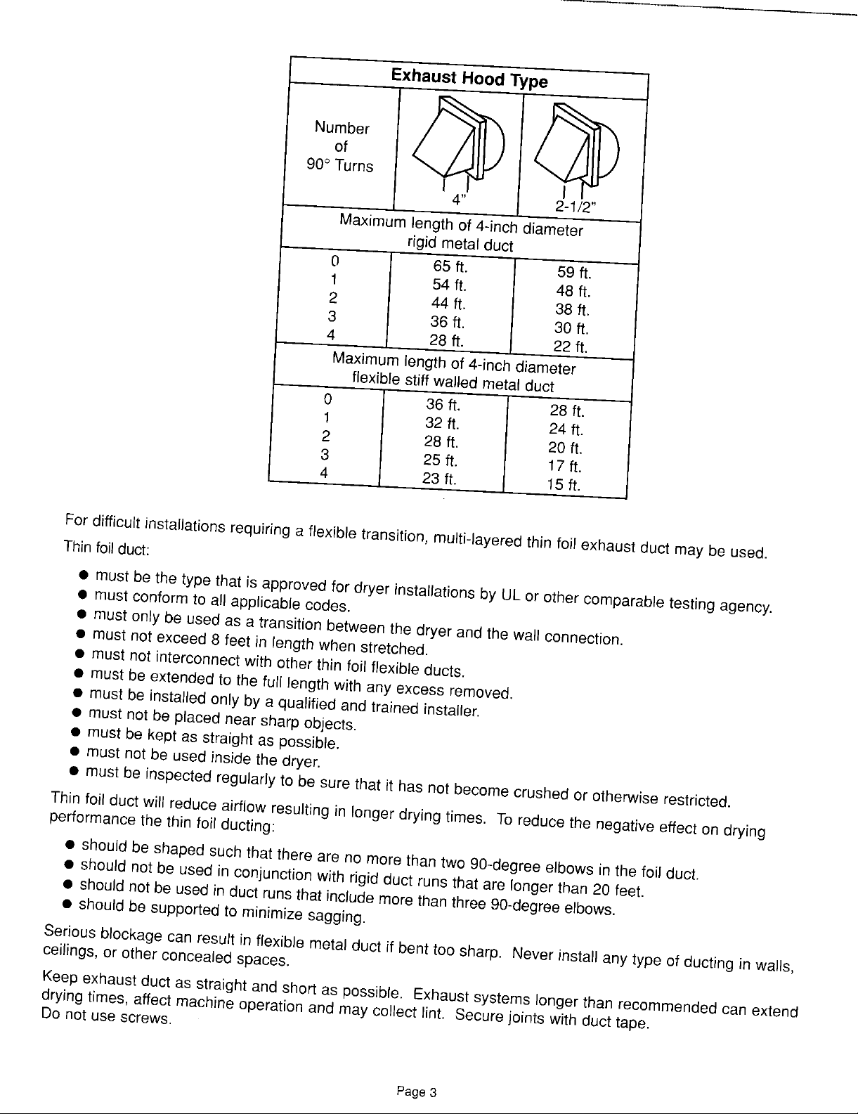
Exhaust Hood Type
90° Turns
4" 2-1/2"
Maximumlength of 4-inchdiameter
rigid metal duct
0 65 ft. 59 ft.
1 54 ft. 48 ft.
2 44 ft. 38 ft,
3 36 ft. 30 ft.
4 28 ft. 22 ft.
Maximumlengthof 4-inchdiameter
flexiblestiff wailedmetal duct
0 36 ft. 28 ft.
1 32ft. 24ft.
2 28ft. 20ft.
3 25 ft. 17ft.
4 23ft. 15ft.
Fordifficultinstallationsrequiringa flexibletransition, multi-layeredthin foil exhaust ductmay be used.
Thinfoil duct:
• must be the type that isapproved fordryer installationsby ULor other comparabletesting agency.
• must conformto allapplicablecodes.
• must only be used as atransition betweenthe dryer and the wallconnection.
• must not exceed8 feet in length when stretched.
• must not interconnectwith otherthin foil flexibleducts.
• must be extendedto the full lengthwith any excessremoved.
• must be installedonly by a qualified and trained installer,
• must not be placed near sharpobjects.
• must be kept as straightas possible.
• must not be used inside the dryer.
• must be inspectedregularlyto be surethat it has not becomecrushedor otherwiserestricted.
Thinfoil ductwill reduce airflow resultingin longer dryingtimes. To reducethe negativeeffecton drying
performancethe thin foilducting:
• shouldbe shaped such that thereare no morethan two 90-degree elbows in the foil duct.
• shouldnot be usedin conjunctionwith rigid duct runsthat are longer than 20 feet.
• shouldnot be usedin duct runsthat includemorethanthree90-degreeelbows.
• shouldbe supportedto minimizesagging.
Seriousblockagecan resultin flexible metal ductif benttoo sharp. Neverinstall anytype of ducting in walls,
ceilings,or otherconcealedspaces.
Keepexhaustduct as straight andshort as possible. Exhaust systemslonger than recommendedcanextend
dryingtimes,affectmachine operationand may collect lint. Securejoints with ducttape.
Donot use screws.
Page 3
Page 4
Exhaust Hood Type
90° Turns
4" 2-1/2"
Maximumlength of 4-inchdiameter
rigid metal duct
0 65 ft. 59 ft.
1 54 ft. 48 ft.
2 44 ft. 38 ft,
3 36 ft. 30 ft.
4 28 ft. 22 ft.
Maximumlengthof 4-inchdiameter
flexiblestiff wailedmetal duct
0 36 ft. 28 ft.
1 32ft. 24ft.
2 28ft. 20ft.
3 25 ft. 17ft.
4 23ft. 15ft.
Fordifficultinstallationsrequiringa flexibletransition, multi-layeredthin foil exhaust ductmay be used.
Thinfoil duct:
• must be the type that isapproved fordryer installationsby ULor other comparabletesting agency.
• must conformto allapplicablecodes.
• must only be used as atransition betweenthe dryer and the wallconnection.
• must not exceed8 feet in length when stretched.
• must not interconnectwith otherthin foil flexibleducts.
• must be extendedto the full lengthwith any excessremoved.
• must be installedonly by a qualified and trained installer,
• must not be placed near sharpobjects.
• must be kept as straightas possible.
• must not be used inside the dryer.
• must be inspectedregularlyto be surethat it has not becomecrushedor otherwiserestricted.
Thinfoil ductwill reduce airflow resultingin longer dryingtimes. To reducethe negativeeffecton drying
performancethe thin foilducting:
• shouldbe shaped such that thereare no morethan two 90-degree elbows in the foil duct.
• shouldnot be usedin conjunctionwith rigid duct runsthat are longer than 20 feet.
• shouldnot be usedin duct runsthat includemorethanthree90-degreeelbows.
• shouldbe supportedto minimizesagging.
Seriousblockagecan resultin flexible metal ductif benttoo sharp. Neverinstall anytype of ducting in walls,
ceilings,or otherconcealedspaces.
Keepexhaustduct as straight andshort as possible. Exhaust systemslonger than recommendedcanextend
dryingtimes,affectmachine operationand may collect lint. Securejoints with ducttape.
Donot use screws.
Page 3
Page 5
DONOT exhaustdryer into any wall, ceiling, crawl spaceor a concealedspace of a building,gas vent,
or any other common ductor chimney. This could createa fire hazardfrom lint expelled by the dryer.
The exhaustductshould end withan exhaust hoodwith a swingout damperto prevent backdraftsand entry
of wildlife. NEVER use an exhausthood with a magneticdamper. The hood should haveat least 12inches
of clearance betweenthe bottom of the hood andthe groundor otherobstruction. The hoodopeningshould
pointdown. NEVERinstall a screenoverthe exhaustoutlet.
Whenpossible,do notexhaust the dryer directly intoa windowwell in orderto avoid lint build-up. Do not
exhaustundera houseorporch.
If exhaustductworkmust run through an unheated area,the duct shouldbe insulated and slope slightlydown
towardsthe exhaust hoodto reducecondensationand lint build-up.
If an existingexhaust system is to be used withyour dryer(s)you must be sure:
• The exhaustsystem meetsall local,state and national codes.
• That plasticflexibleduct is not used.
• To completelyinspect and cleanall lint accumulatingfrom the interiorof the duct.
• The ductis not kinkedor crushed.
• The exhaust hooddamperopens andcloses freely.
Inspectand cleanthe interiorof the exhaust system at leasttwice a year. Disconnectelectricservice priorto
cleaning. Check gas line on gasdryers anytimethe dryer is moved.
Frequentlycheckto be sure the exhausthooddamper opensand closes freely.
WASHER REQUIREMENTS
Waterpressureof 20to 120 p.s.i,is requiredto correctlyfill the washerto the proper levels.
DRAIN FACILITY
Recommendedheightof the stand pipe is 36 inches. Ifthe stand pipe is less than 36 incheshigh,the drain
hoseshould be routedthroughthe clip to raise the hoseto the properheight. Standpipe must be large
enoughto acceptthe outsidediameterof the drain hose.
Without the 36 inches high elevation, water may run out of the washer prematurely. Shouldthe washer
fill and drain atthe sametime could indicatethat the drain hosehas notbeen elevatedto the properheight.
Thedrain hose is attachedat the factory.
FLOORING
For bestperformancethe washer must be installedon a solidly constructedfloor. Wood floors may needto
be reinforcedto minimizevibration and/or unbalancedloadsituations. Carpeting and softtile surfacesare
contributingfactorsin vibration and/ortendency for awasher to moveslightly during the spin cycle. Never
installthe washer on a platform or weak supportedstructure.
LOCATION CONSIDERATIONS
It is recommendedthewasher never be installedin areaswhere water may freeze sincethe washer will
always maintainsome water in the watervalve, pumpand hose areas. This can cause damage to belts,
pump, hosesand other components. Operatingtemperatureshould be above60°F.
Page4
Page 6

GAS REQUIREMENTS
Useonly Naturalor LP (liquidpropane) gases.
THE INSTALLATIONMUSTCONFORMWITHLOCALCODES,OR IN THEABSENCEOF LOCALCODES,
WITHTHE NATIONALFUELGAS CODEANSI/Z223.1, LATESTREVISION(FORTHE UNITEDSTATES),
OR WITHTHE CAN/CGA-B149INSTALLATIONCODES(FOR CANADA).
A gas dryer is equippedwith a burner orifice for operation on NATURALgas. If the dryer is to be operated
on LPgas, it mustbe convertedfor safe and proper performanceand mustbe converted by a
qualifiedservice technician. Conversionkits from NATURALto LP,or LP to NATURALareavailable
through your localdealer (seeAccessories). If other conversionsarerequired,check with the localgas utility
for specific informationconcerningconversionrequirements.
Eachdryerwill provide an input of 22,000 B.T.U.per hour.
A 1/2inchgassupply lineis recommendedandmust be reducedto connectto the 3/8 inchgas line onthe
dryer.
The internal gas shut-off isaccessedby removingthe access panel on the dryer. The shut-offis positioned
for easy accessnear the gasvalve.
The NationalFuelGas Code requiresthat an accessible,approvedmanual gas shut offvalve be installed
within 6feet of the dryer.
Additionally,a 1/8 inch N.P.T.(NationalPipeThread) pluggedtapping, accessiblefor test gaugeconnection,
mustbe installedimmediatelyupstreamof the gas supplyconnectionto the dryer.
Thedryermustbe disconnectedfromthegassupply pipingsystemduringanypressuretestingofthesystem.
DO NOT re-useold flexible metalgas line. Flexiblegas line mustbe design certifiedby AmericanGas
Association(CGAin Canada). NOTE: Any pipejoint compoundused must be resistantto the actionof any
liquefiedpetroleumgas.
NOTE: Asa courtesy,most local gas utilitieswill inspect a gas applianceinstallation.
GAS IGNITION -
Thedryeruse anautomaticignitionsystemto ignitethe burner. There is no constant burning pilot.
GROUNDING
• Improperconnectionof the equipment-groundingconductorcan resultin a risk of
electricalshock. Checkwith a qualifiedelectricianor servicemanifyou arein
• Do not modifythe plug providedwith the appliance- ifit will not fitthe outlet,
havea properoutletinstalledbya qualifiedelectrician.
• Toprevent unnecessaryriskof fire, electricalshock or personalinjury,all wiring
and groundingmust be done in accordancewith the NationalElectricalCode
I 1_0 I doubtas to whetherthe applianceis properlygrounded.
the personalresponsibilityand obligation of the applianceowner to provideadequateelectrical services
forthis appliance.
• All gasinstallationsmustbe done in accordancewith the NationalFuelGas CodeANSI/Z223.1-Latest
Revision(forthe U.S.) orthe CAN/CGA-B149InstallationCodes-LatestRevision(forCanada) and local
codesand ordinances.
ANSI/NFPA,No.70-Latest Revision(for U.S.)or the CanadianElectricalcode
CSAC22.1-LatestRevision (for Canada)and localcodes and ordinances. It is
Page 5
Page 7
ELECTRICAL REQUIREMENTS WARNING- TOprevent
unnecessaryrisk of fire,
NOTE: Wiring diagram is located inside the access panel, electricalshock or
personalinjury,all wiring
Export models (not U.S. or Canada): and grounding must be
See Additional Instructionsfor Export Modelson the following done in accordance
pages, with local codes, with
the National Electrical Code,
GROUNDING ANSl/NFPA(for the United States)
or the Canadian Electrical Code
Eachdryer must be grounded. In the eventof malfunctionor CSAC22.1 (for Canada).
breakdown,the ground will reducethe risk of electricalshock by
providing a pathof leastresistancefor electricalcurrent.
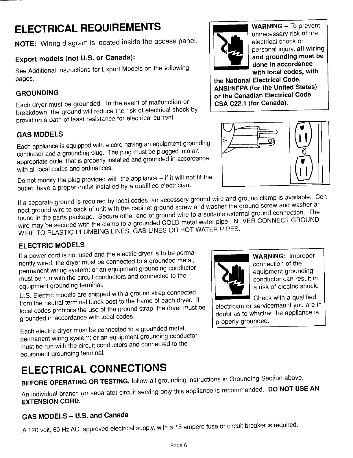
Eachapplianceisequippedwitha cordhavinganequipment-grounding
conductoranda groundingplug. Theplug mustbe pluggedintoan
appropriateoutletthatis properlyinstalledandgroundedinaccordance
withall localcodesandordinances.
Do notmodifythe plugprovidedwith theappliance- if it will not fit the
GAS MODELS _
outlet,have a properoutlet installedby a qualified electrician.
If a separateground is requiredby local codes,anaccessorygroundwire and ground clamp isavailable. Con-
nectgroundwireto backof unitwiththecabinetgroundscrew and washertheground screwand washerar
foundinthe partspackage. Secureotherend of groundwire to a suitableexternalgroundconnection. The
wire maybe securedwith the clampto a groundedCOLDmetalwater pipe. NEVER CONNECTGROUND
WIRETO PLASTICPLUMBINGLINES,GAS LINESOR HOTWATERPIPES.
ELECTRIC MODELS
If a powercordis notused andtheelectricdryer isto be perma-
nentlywired,thedryer must beconnectedto a groundedmetal, WARNING: Improper
permanentwiringsystem;oran equipmentgroundingconductor connectionof the
mustbe run withthe circuitconductorsandconnectedto the equipmentgrounding
equipmentgroundingterminal, conductorcan result in
U.S.Electricmodelsareshippedwith a groundstrap connected
fromthe neutralterminalblockpostto theframeof eachdryer. If Checkwith a qualified
localcodesprohibitstheuse ofthe groundstrap,the dryer mustbe electricianor servicemanif youare in
groundedinaccordancewith localcodes, doubt asto whether the applianceis
properlygrounded.
Eachelectricdryermustbe connectedto a groundedmetal,
permanentwiringsystem;oran equipmentgroundingconductor
mustbe runwith the circuitconductorsandconnectedtothe
equipmentgroundingterminal.
a riskof electric shock.
ELECTRICALCONNECTIONS
BEFOREOPERATINGOR TESTING,follow all groundinginstructionsin GroundingSectionabove.
An individualbranch (or separate)circuit servingonly thisappliance is recommended. DO NOT USEAN
EXTENSIONCORD.
GAS MODELS - U.S. and Canada
A 120volt,60 HzAC,approvedelectricalsupply,witha 15amperefuse orcircuitbreakerisrequired.
Page 6
Page 8

ELECTRIC MODELS - U.S. and Canada
A 120/240volt, 60 HzAC approvedelectricalservice fusedthrougha 30amperefuseor circuitbreakeronboth
sidesofthe lineis requiredforthe dryeranda 120volt60 HzACapprovedelectricalsupplywith a 15ampere
fuseor circuitbreakerforthe washer.
Ifa powercord is used,the cord should be pluggedinto a 30 ampere receptacle.
U.S. ELECTRIC MODELS
The power cord is NOTprovidedwith U.S. electric model dryers.
IMPORTANT: Whenpermittedby localcodes, the dryerelectrical supply may be connectedby meansof a
newpowersupply cord kit, markedfor usewith clothesdryer, that is U.L.listed, ratedat 120/240volts
minimum,30 ampereswith three No. 10copperwire conductorsterminatedwith closedloop terminals,
open-endspade lugs with turnedup ends orwith tinned leads.
Donot reuse a power supplycordfrom an olddryer. The powercord electric supplywiring mustbe retained
at the dryercabinet with a suitable ULlisted strain relief.
Ifthe dryer is to be installedin an area where local codesdo not permitgroundingthrough neutral, onlya 4
conductorpower cord, ratedand terminatedas above,may be used.
120/208Volt Electrical Systems:
A U.S.electricwasher/dryermustbe convertedif it is to operateon a 120/208volt electricalsystem. A heating
elementconversionkitis availableforthe dryer along with a transformerforthe washer (seeAccessories).
CANADIAN ELECTRIC MODELS
All Canadian models are shipped with the power cord attached.
It is not permissible to convert a dryer in Canada to 208 volts,
Additional Instructions for Export Models
(not U.S. or Canada)
Contactthe distributorthat sold the appliance or: Maytag International,8700W. Bryn MawrAvenue,Chicago,
IllinoisUSA 60631,773-714-0100, for informationon product,shippingdamage,replacementpartsand
accessories.
Maytagmodels manufacturedfor operationon 60 HzAC are not designedfor useon 50 HzAC
electricalservice and conversionof the productfrom 60to 50 Hz operationis not recommended. For
additionalinformationon 50 Hz products,contact Maytag International.
The electricservice requirementscan befound on the data labellocated onthe front of the dryer behindthe
door.
EXPORT ELECTRIC MODELS
Exportelectricmodelsare manufacturedfor operationon either 230/240volt, 50 Hzor 220 volt, 60 Hz
approvedelectricservice. A two-wireapprovedelectricalservicewith a30 amperefuse or circuit breakeris
required. The dryer must be properlygroundedwith a groundwire.
IMPORTANT:When permitted by local codes,the dryer electricalsupply maybe connectedby meansof a
newpowersupply cord kit, markedfor use with clothes dryers, that is agencylisted, ratedat 240 volts
minimum,30 ampereswith two No. 10copper wire conductorsterminatedwith closedloop terminals,
open-endspade lugs with turnedup ends orwith tinned leads.
Donot reuse a power supplycordfrom an old dryer. The powercord or electricsupplywiring must be
retainedat the dryer cabinetwith a suitable agencylisted strain relief.
Page7
Page 9

ADDITIONALINFORMATION
REPLACEMENT PARTS AND ACCESSORIES
Ifthe dryer requiresreplacementpartsor accessories,contactyour local Maytagdealer fromwhom you
purchasedyourapplianceor:
MaytagCustomerService
240 EdwardsStreet, S.E.
Cleveland,Tennessee 37311
Phone615-472-3333,for informationon the nearestauthorizedMaytag PartsDistributor.
EXPORT MODELS
Contactthe CommercialDistributorfromwhom you purchasedyour applianceor:
MaytagInternational
8700 W. BrynMawrAvenue
Chicago, Illinois,USA 60631
Phone312-714-0100,for informationon the nearestauthorizedMaytagParts Distributor.
Page 8
Page 10

To install...
1•Carefullyremoveany packagingmaterialsfrom the outsideof the
washer. Set asidetwo cornerpostsfor installation. IMPORTANT:
Noticethat the hoses and powercord aretied upwith a shipping
strap. Thestrap should not be cut or removed until the machine
is readyto be installed.
Figure 1
2. Laytwo cornerposts behindthe washer and _ ___ -•
gentlytip the washerover on to itsback. 4L_____j..jiI if///
3. Usinga screwdriver,pry off the crate bottom
wire retainers(2) and removethe cratebottom
fromthe washer.
Figure2 Figure3
4. Locatetwo 1/2inch hexshippingbolts on bottomof
metalbase. Removeboth bolts, freeingthe tub and Shipping __
suspension. DONOTBEALARMEDas the lastbolt Bolts
restingagainstthe back of the washer.
is removed,the tub will jumpto a positionwhere it is _
5. Loosenthe four adjustablewasherlegs and lock nuts. Install
vinyl feetfound in installationpackage. Feetcan be more _--'---
easily installedwhen immersedin hotwater beforeinstalling.
Carefullyraise the washer backto an upright position.
6. At the installationsite, locatethe metal bucklesattachedto
the shippingstraps at backof washer. Carefullycut away
strapsnear both buckles,completely removingboth
bucklesfrom the washer.
Figure6 Figure7 removed.
Figure4 __'_
Pull loose straps
from backof washer
oneat a time until
all straps have been
Insertinlet hose screensin the ends of the hot and cold inlethoses. Screensare foundin the
miscellaneouspartspackage. Domedsurface is to facethe valve.
Page9
Page 11

7, Open the washerdoor 90degrees. Removethe tape holding the accesscover. (Seefigure 8.)
Removethe accesscover by slidingforward. DO NOT pull up. (Seefigure 9.)
Figure8 Figure9
8, Open the AccessoryCartonand removethe access panel. Discardshipping materials. Gas dryers
includea gas pipe assemblyin the carton. (Seefigures 10& 11.)
Figure 10 Figure11
For Gas Dryers: Removered and bluethreadprotectors fromgas pipe. Knockout square hole in rear of
supportand insert gas pipe throughhole. (See figures 12a-d.) Allow pipe to rest on inside
of support. (See figure 13.) Makesurevalve is closed. (Seefigure 13a.)
Page 10
Page 12

Figure 12a Figure 12b
Figure12c Figure12d
Figure13 Figure13a
Page 11
Page 13

9. For nonalcove installations, utilities and
venting can be connected after units are
stacked.
For alcove installations:
Securetheexhaustbrackettothe rearofthe
washerwith screwsprovided.
(Seefigures14,15& 16.)
Unsnaphosesfromplastic hosecaddy,leaving
caddyattachedto thebackofthe cabinet.
Connectfillhosestofaucets(hotwaterhoseis
the left hoseas youstandfacingthe front ofthe
washer). Insertthe drainhosein thestandpipe
recommendedheightof 36 inches,minimumof
24inches. Note: Ifdrainhoseisnotsecurein
thestandpipe, usea portionofthe shipping
strapto securethedrainhoseto thestand pipe. Figure 14
Makesurethatdrainhoseis securedto the hose
caddyafter installation.Fillhosesarenot to
besecuredtocaddy. Turnonwaterand checkfor leaks.
Moveunitintoposition,levelandtightenthe levelinglocknutsonthe legs. Securetheventpipeto the
exhaustbracket. (See figure 16.) MAKINGSUREFIRSTTHATOUTLETISNOTENERGIZED,plug
washerintooutlet.
Figure15 Figure 16
Page 12
Page 14

For gasdryers applyjoint compoundor about 1-1/2 wraps of Teflontape _ 1
over threadedconnectionon the end of the gas pipe. (See figure 17.)
An elbow is recommended,for additionaldepth, pointing downto allow
the unit to be locatedfurther back into the alcove. (Seefigure 18.)
Note: Pipejoint compoundmust be resistantto the action of anyliquefied
petroleumgas.
Add additionalfittingto connectthe 3/8 inch gaspipe to a female threaded
end of a 3/4 inchflexibleconnector makingsure the connectionis tight. Figure 17
(See figure 19.)
Makesuretheshutoffvalveon theendof thegas pipe is closedandconnectto the gassupply.
Opengas servicevalve and check all gassupply connectionsfrom servicevalveto shutoffvalve for
leaksusinga soap solution, DONOT use an openflame to checkfor
gas leaks. Ifbubbles occur,tightenthe connections and recheck.
NOTE: Asa courtesy,manylocal gas utilitieswill inspect a gas applianceinstallation. Check with your
local utility to see if this serviceis providedin your area.
NOTE: The minimumpermissiblegas (naturalor mixed)supplypressure forpurposesof input
adjustmentis 4.5 inchesof water.
1
Figure18 Figure 19
1 0, Laythe dryer on itsside using 2 of the
cardboardcornerpoststo protectthe side of
the cabinet. (See figure20.) Remove
protectivefilm from the control panel, and using
a 5/16 inch nut driver,removethe shipping
bolts (3) securingthe wood shippingbaseto
the bottom of the upperdryer.
Figure20
Page 13
Page 15

11, For gas dryers:
Removeyellowthread protectorfrom union. (See figure21.)
Positionthe dryerupright in front of the washer,with the rear of the dryer facingthe washer. To prevent
damageto floors do notslide the dryeron the floor!
NOTE: Forgasdryer alcove installation,plug powercord for dryer intoan outlet MAKINGSURE FIRST
THATOUTLETIS NOTENERGIZEDpriorto liftingdryer ontowasher.
Holdingthe baseto support bracket,removethe 2 #10 hexhead screwsand basesupport brackets
(notehowthe bracketsare inserted)located at the front of the dryer base,markedwith orange labels.
(See figures22 &23.) NOTE: Bracketsand screwswill be used later.
A protectiveconduit (plastic)is provided for the powercord. Installthe conduit overthe power cord.
The conduitis slit to facilitate installation. (See figure24.)
Yellow
Thread
Protector Hex Base
Head
Screw Bracket
Figure21 Figure22
Base
Su
Bracket
Figure23 Figure24
Page 14
Page 16

TO MAKE ELECTRICALCONNECTIONFOR U.S.DRYERS
Reviewelectricalrequirementsonpage 6 of theseinstructions.
12, For electricdryers: I
CONNECTION. The dryer frame is groundedto the neutralconductor
at the terminalblock. A 4-WIRE SYSTEMCONNECTIONis required
IMPORTANT- All U.S. modelsare producedfor a 3-WIRESYSTEM /®l _er_ I®
for new or remodeledconstruction,mobile homes, or if local codesdo
notpermit groundingthroughneutral. If the 4-wiresystem is used, _ _ |
the dryerframecannot be groundedto the neutralconductorat the / O
terminalblock. Referto the followinginstructionsfor 3- and 4-WIRE ,Figure 25
SYSTEMCONNECTIONS.
Removethe terminalblock coverplate. (See figure25.) I i
B
I
A protectiveconduit(plastic)is providedforthe powercord. Cutthe
conduitsothat it isapproximately18 inchesshorterthanthe power
cordandthreadthe power cordthroughthe conduit. (Seefigures26 &
27.)
Insertthe power cord with a U.L.listed strain reliefthroughthe hole Figure26
providedinthe cabinetnearthe terminal block. Note, a strain relief
must be used.
3-WIRE SYSTEM CONNECTIONS
Do not loosenthe nutsalready installedonthe terminal block. Be
sure they are tight. Usea 3/8 inch deep nut driver.
Ifthe powercord hasterminals,placethe terminals overthe existing
nutsonthe posts. The neutral (whiteor center wire on power cord) Figure27
conductormustalways be connectedto the center (silvercolored)
postofthe terminal block. 3-Wire System with
Cord Attached
Securein placeusingthe nuts providedin the parts oackage. If the ,__,,_Power
powercord does not haveterminals, use the cuppedwashers ahead
of the nuts. Ground
Besure the terminal blocknuts aretight. Secure the power cord in
position. Tightenthe strain reliefscrew(s) in order to clamp the strain
reliefto the cord. (See figure28.)
Replacethe terminalblock cover. Neutral
BEFOREOPERATINGOR TESTING,followthe grounding directions
on page 5. Strain
4-WIRE SYSTEM CONNECTIONS relief
Removetheground strapscrew fromthe terminal block support. Fold Figure28
the groundstrap over so bothends of the ground strap are attached
to the centerterminalblock post. 4-Wire System with
Connectthe neutral (white)conductorof the cord to the center (silver) Power Supply Attached
postof the terminal block. Connectthe grounding (green)wire of the
cord to the terminalblock supportusingthe groundstrap screw. -- ° Folded
Connectthe redand black wires of the cord to the outer posts ofthe Neutral _ _.'_'_ Ground
terminalblock. Post ----. __/ StrapBe surethe terminal blocknuts are ontight. Securethe power cord in
positiOn.reliefto theTightencord,the(seeStrainfigurerelief29.)screw(s)in order to clamp the strain •///__ /e NeutralReplacethe terminalblock cover. Strain
WARNING: If convertingfrom 4-wireelectricalsystemsto 3-wire,the o _ Relief
groundstrap mustbe reconnectedto terminalblock supportto ground (_ 4''/
thedryer frameto the neutral conductor. Figure29
Page 15
Page 17

2-WIRE AND GROUND SYSTEM CONNECTIONS
Removetheterminalblockcoverplate.
Insertthepowercordwithanagencylistedstrainrelief (" _
throughtheholeprovidedinthe cabinetneartheterminal _ o
block. Note,a strainreliefmustbe used. __
Donotloosenthenutsalreadyinstalledonthe terminal Neutral
block. Besuretheyaretight. Use a 3/8 inchdeepwell Post" Power
socket. Ground
supportusingthe groundscrew. (Seefigure 30.)
Ifthe powercord has terminals, placethe terminals over
Securethe powercord groundwiretothe terminal block _;Je ,Wire
the existing nuts on the posts. The neutralwire in power
cord mustbe connectedto the center (silvercolored Power
postofthe terminal block. Neutral o f-_ _. • and
Securein placeusing the nutsprovidedin the parts ("Ah JF"/- strain
usethe cuppedwashersahead of the nuts.
package. If the powercord does nothave terminals f relief
Be surethe terminal blocknuts aretight. Securethe Figure30
powercord in position. Tightenthe strainrelief screw(s)
in ordertoclampthestrainreliefto the cord.
2-Wire and Ground System
o o Cord
cord
Replacethe terminalblock cover.
BEFOREOPERATINGOR TESTING,be surethe machineis properlygrounded.
EXPORT GAS MODELS
Exportgas modelsare manufacturedfor operationon either 230/240 volt, 50 Hz or 220volt, 60 HzAC
approvedelectricalservicewith a 15amperefuse or circuitbreaker.
Exportgas models havebeen manufacturedfor use with natural gashaving a higher heatingvalue of approxi-
mately 1025 BTUpercubic foot. Conversionto LPgas with a higherheating value of approximately2500
BTU per cubicfoot must be performedby a qualified servicetechnician. A conversionkitis available.
For electric dryers in alcove installation:
MAKINGSURE FIRST THAT OUTLET IS NOT ENERGIZED,plugpowercordfor dryerintoan outletpriorto
liftingdryer ontowasher.
13.Makesurethat the exhaustseal is in placeand evenwith the end of the exhaustpipe.
(Seefigures31 & 32.)
Figure31 Figure32 Figure33
Makesurefront tabs are not bent, use screwdriverto straightentabs if bent. (See figure33.)
Page 16
Page 18

1 4, Two people,one on each side,grasp andliftthe dryeronto the washer(seefigure 34),takingcare not to
bendthe tabs locatedtowardsthe front of the washer. Slide the upperdryertowardthe rear makingsure
that theguidesfall betweenthe railson the supportof the washer. (Seefigure35.)
WARNING: Makesure POWERIS NOT SUPPLIEDTO OUTLETduringinstallation.
Whenplacing the dryeronto the washer, makesure the POWERCORDIS NOTPINCHEDbetween
the washer andthe dryer or betweenthe exhaust pipeand bracket. If the dryercannot be pushedall
the way back, check to see if the power cord is being pinchedbetween the back ofthe dryer and the
exhaust bracket.
Makesure that SHUT-OFFFOR UTILITIES(electric,gas and water) WILL BEACCESSIBLEafter the
applianceis installed.
Figure34 Figure35
15.Checkto make sure the tabson the washer are engagedin slots atthe front ofthe base ofthe dryer.
(See figures36 & 37 - somecomponents removedfor clarity.)
Front Right
Dryer
Base
O
Figure36 Figure37
Rotateforward to check engagement.
Page 17
Page 19

16.Insert the base to support brackets (removed in step 11) on both sides the upper base and secure with
the screws also removed in step 12. (See figures 38 & 39.)
.... " _" o ppL'u--or"
\\\
\\
Dryer _\_ -\
Base - _
"/ Tab /_
...., _; Screw
,\
Figure 38 Figure 39
17.Raise gas pipe with shut off valve up and secure to gas valve union• (See figure 40.) Tighten fitting
with a crescent wrench being careful not to over tighten. (See figure 41.)
Do not apply teflon tape or pipe sealing compound to the threads of the shut off valve. This is a
brass expansion sleeve fitting.
Figure 40 Figure 41
Page18
Page 20

18.Openthe gas shut offvalve inside the upperdryer (see figures 42 & 43), and check the union
connectionto the gas valve for leaksusinga soap solution,DO NOTuse an open flame to check for
gas leaks. If bubblesoccur,tighten the connectionsand recheck. Makesure notto let solutiondrip
into anyelectricalconnectoror component.
NOTE: As a courtesy,manylocal gas utilitieswill inspect a gas applianceinstallation. Checkwith your
local utilityto seeif this service is provided inyour area.
NOTE: The minimumpermissiblegas (naturalor mixed)supplypressure for purposesof input
adjustmentis 4.5 inchesof water.
Figure42 Figure43
19.Removewire harnessesand plastic clips from base (see figure44) andconnect each harnessto the
connectorin the washer makingsure lockingtabs areengaged, and harness is tucked out ofthe wayof
the dispenser. (Seefigures45 & 46.)
Figure45
7 ii_iii
Figure44
L
Figure 46
Page 19
Page 21

20, Removethe accesscover screw (see figure47),alongwith the orangelabel onthe accesscover. Make
sure emergencydoor releaseisaccessibleafteraccesscover isinstalled (Seefigures48 & 49.)
m
Figure47 Figure48
Figure49
21• Secure the accesscoverto the baseof the _"
upperdryer using a ratchetandthe #10 hex
head accesscover screw removedin step 20.
(See figure50.) NOTE: Apply rearward
pressureon the accesscover while applying
finaltorque to screw.
Figure50
Page 20
Page 22

22.Rotateaccesspanel intoposition, and securewith whiteor almondscrewssuppliedin the
miscellaneousparts package. (Seefigure 51.) Removeprotective filmfrom fasciaand tape from
edgesof control panel. (Seefigure 52.)
23.Removewasherand dryer timer knobsfrom miscellaneouspartspackage and insert them on the
respectiveshafts. NOTE: Timershafts are differentbetweenthe washerand dryer. (See figure53.)
.....
!
Figure51
Figure53
Figure52
24. For nonalcove installations (where there is access to the rearof the appliance):
Plug in powercordforthewasherand dryer.
Removethe 2 outerscrewsinthe backofthe cabinetclosesttothesides(see figure54) andsecure
the securitybrackets(2) to the uppercabinet. NOTE: Slottedholeis orienteddown. (See figure55.)
Do nottightenuntilthe nextstep iscompleted.
CabinetScrew Cabinet
Screw
Figure54 Figure55
Page 21
Page 23

Securethe other ends ofthe security brackets(2) to the support using #10 hex headscrews providedin
the miscellaneouspartspackage. (See figure 56.)
i
Figure56
Ifappliancehas notbeen leveled, moveit into position,check itwith a level and makethe necessary
adjustmentsto the levelinglegs. Once level,tighten the levelingleg lockingnuts with a wrench.
Connectthe exhaustducts to ductwork by insertingthe elbowwhile holdingontothe exhaust seal.
(Seefigure 57.)
Figure57
25. Removethe tape and cardboardprotectionfor the door on the lowerdryer.
Page 22
Page 24

26.Directions for reversingthe dryer door:
1. Removethe hinge holecovers and screws. Movethe door catchcover tothe oppositeside.
2. While supportingthe door, remove4 screws inthe hingesthat secure the hingesto the cabinet and
setthe door down.
3. Movethe following partsto the oppositeside of the door: 2 hinges and 4 hinge screws,4 door
screws,door strikeand screw,inner door cover plateand screw.
4. Attachthe doorto the oppositeside of the cabinet usingthe 2 countersunk hinge screws.
(Seefigure 58.)
5. Replacethe hingehole coversto the opposite side.
.-" .... "-. _ ' Door
/" _', _" _ %-- Screws
" "", str,ka
I I 1
t _,, Cover Coy ,
x _+ --uoor
• .---22-222222-222J _ Screws
'_,, _/[/Figure58 "
Door Catch Counter Sunk Screw
27.Directionsfor reversingthe washerdoor:
1. Swingdoor fully openand support it while removingfour hingescrews (whichhold hingesto door
assembly).
2. Setdoor asideandtransferfourcolormatcheddoorscrewstothe oppositeside ofthe doorassembly.
3. Removeonescrew holding top hinge to cabinet and one screw holdingtop hingecover to cabinet
(oppositeside).
4. Removehinge and bracketfrom cabinet by movingthem upand down to a positionwherethey are
released.
5. Installhinge and bracketin swappedlocationsand drivescrewsto attachthem securelyto the cabi-
net.
6. Comparetop hingeandtop bracketto bottom hingeand bottom bracketfor correctassemblyposi-
tion.
7. Repeatprocedures4 through 6 for bottomhingeto cabinetand bottom bracketto cabinet.
8. Supportdoor infully open position on hingeside and drive four screwsto secure attachhingesto
doorassembly.
9. Closedoor andcheck to see that clotheswasher operatesproperly.
// / / '/"_" Door
f _1 7it Hole I ng
I t I_t Covers
Counter Sunk Screw_,
Screws
Figure59
,,,,!,\_...... +++
"-_.!,\.,..___ _ _ .. / _ _ _ "_+ _' _ Screws
Page 23
Door
Page 25

INSTALLATION ACCESSORIES FINAL INSTALLATION CHECK LIST
i •Vent hood- 4" (10.16cm)opening- 059129 _ Instructionand InstallationKit havebeen
'_ •Aluminumpipe - 4" x 24" (10.16cmx 60.96cm) removedfrom dryer.
_ - 059130 [] Shippingboltsandstrapshavebeenremoved.
! , _ •Aluminumelbow- 4" (10.16cm)- 059131 [] Assurethatthedryer isslidback and is
,_ •Aluminumwindowplate - 15"x 20" (38.10cmx securedtothe washer.
50.80cm)-4" (10.16cm)hole- 059134 [] Vinyl feet havebeen installed.
i •Flexiblealuminumvent duct - 4" (10.16cm) [] Washer/dryeris levelwith all legs firmly on
ii diameter- 38" (81.28cm)length stretches to the floor,with the lock nutstightenedagainst
' 8' (2.44cm) 304353 the base.
! • Clampfor flexible aluminumduct - 304630 _ Drainhose is properlylocated into drain
_: •Exhaustduct kit for base or left sideexhausting facility,snapped into drain hosestrap and is
....ii - 33001881 nbt kinked.
•Rectangularventkits - 059144 [] Gas Models- gas is turned on,there are no
i, • Backdraft damper4"- 059146 gas leaks.
n
i! • NATURALto LPconversionkit [] Water is turned on and checked for leaks at
i - LPto NATURALconversionkit- 33001287 C]
30619_
faucet andwater valve connections.
Washerfills properly on all temperature
•Anchorbracket kit - 303740 selections.
_i • Heatingelementconversionkit, _ Exhaustduct work is hookedup andjoints
i_ 208v.,- 308590 (NOT FOR CANADA) taped.
ll •Groundingwire - 311155 [] Use rigidor stiffwalled flexible metalvent
!t •Ground clamp- 301548 material.
i! • Powercords - 240v, 30A [] Plasticflexibleduct is NOTused.
I_ 4' - 3-wire- 33001780 [] Washer and dryer areplugged into electrical
5' - 3-wire- 33001822 outlet and areproperly grounded.
6'- 3-wire - 33001823 [] Testfor properoperationby runningthe
10'- 3-wire- 33001838 washerthrougha complete cycle.
4' - 4-wire- 33001781
6'- 4-wire - 33001824 1. SelectCotton/Sturdy,Hot/Coldand Max
Extract. Makesure the Extra Rinse
6'-4-wire- 33001825 option is not selected.
2. Setthe timerintothe Heavy-Normal-Light
washband andpresstheStart/Stopbutton.
3. Verifythe washer isfilling fromthe hot
watervalve.
4. Verifythe washerstops filling.
5. PushStart/Stopto stop washer.
6. Set the timer intothe Final Rinse
incrementand pressthe Start/Stop
buttonto restart the washer.
7. Verifythe washer is filing fromthe cold
watervalve.
8. Verifythe washer stopsfilling.
9. Wait 30 seconds for the timerto advance
itself one increment intoSpin.
10. Verifythe washerspins. This will take
several minutesas the door needsto lock
and distributethe load. _-
11. Pullonthe doorto makesure it haslocked.
12. Resetthe washerto start position.
[] Dryer runs, heats,shuts off.
Page 24
 Loading...