

Maytag MEDZ400TQ, MEDZ600TB, MEDZ600TE, MEDZ600TK, MEDZ600TW Dimension Guide
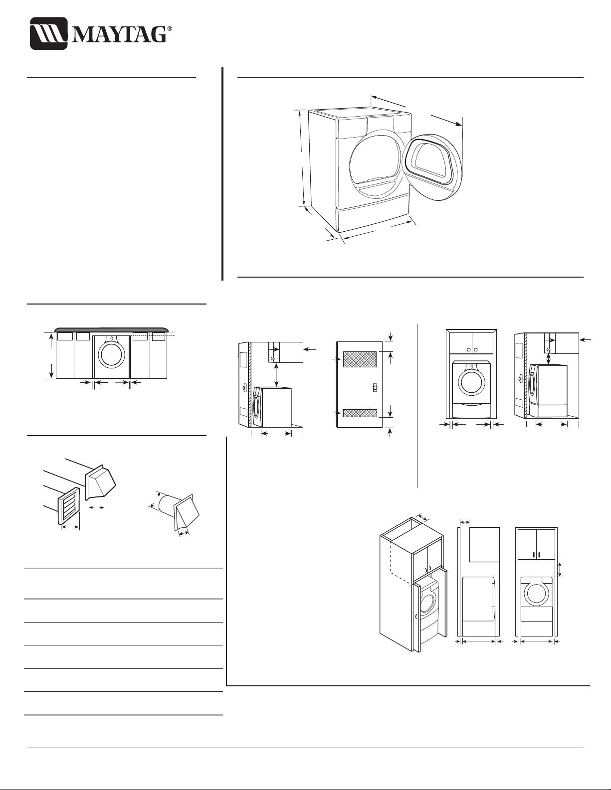
PRODUCT MODEL NUMBERS OVERALL DIMENSIONS
EXHAUST VENTING
MEDZ400T MEDZ600T
Because Whirlpool Corporation policy includes a continuous commitment to improve
our products, we reserve the right to change materials and specifications without notice.
Dimensions are for planning purposes only. For complete details, see Installation
Instructions packed with product. Specifications subject to change without notice.
Ref. W10112937
10-04-07
RECESSED AREA AND CLOSET INSTALLATION
UNDERCOUNTER INSTALLATION
For closet installation, with a door, the minimum ventilation openings in the top and
bottom of the door are required. Louvered doors with equivalent air ventilation openings
in the top and bottom are acceptable.
Dimensions shown are for minimum spacing.
Recommended hood styles
Dryer only
Dryer on pedestal
Angled hood style is
acceptable.
Select the route that will provide the straightest and most direct path
outdoors. Plan the installation to use the fewest number of elbows and turns.
Use the fewest 90° turns possible.
Do not use vent runs longer than specified in vent length chart.
Determine the number of elbows you will need.
Electrical: This dryer requires a 3 or 4 wire,
single phase, 120/240 volt, 60 Hz., AC only
electrical supply (or 3 or 4 wire, 120/208 volt
electrical supply, if specified on the serial/rating
plate) on a separate 30-amp circuit, fused on both
sides of the line. A time-delay fuse or circuit
breaker is recommended. Connect to an individual
branch circuit. Do not have a fuse in the neutral or
grounding circuit.
Exhaust venting: Exhaust your dryer to the
outside. Four inch diameter vent is required. Rigid
or flexible metal exhaust vent must be used. Do not
use plastic or metal foil vent. Exhaust outlet hood
must be at least 12 inches from the ground or any
object that may be in the path of the exhaust.
Recommended installation
spacing for cabinet installation
For cabinet installation, with a door, the
minimum ventilation openings in the top
are required.
* Most installations require a minimum 5”
(12.7 cm) clearance behind the dryer for
the exhaust vent with elbow. See
Installations Instructions, “Venting
Requirements.”
®
EPIC z™Electric Dryer
A. Side view - closet or confined area
B. Closet door with vents
*Required spacing.
**For side or bottom venting, 0" (0 cm)
spacing is allowed.
*Required spacing.
A
B
A. Recessed area
B. Side view - closet or confined area
*Required spacing.
**For side or bottom venting, 0" (0 cm)
spacing is allowed.
*Required spacing.
**For side or bottom venting, 0" (0 cm) spacing is allowed.
A
B
36"
(91.4 cm)
*28.65"
(72.77 cm)
27"
(68.6 cm)
50"
(128.27 cm)
2"*
(5 cm)
36" min
(91.4 cm)
1"*
(2.5 cm)
27"
(68.6 cm)
1"*
(2.5 cm)
B
A
4"
(10.2 cm)
4"
(10.2 cm)
A . Louvered hood style
B . Box hood style
Number of
90° turns
or elbows
NOTE:
inside the dryer. To determine maximum exhaust length, add one
90° turn to the chart.
Type of
vent
0Rigid metal
Flexible metal
1Rigid metal
Flexible metal
2Rigid metal
Flexible metal
3Rigid metal
Flexible metal
4Rigid metal
Flexible metal
Side and bottom exhaust installations have a 90° turn
4"
(10.2 cm)
Box or
Louvered
hoods
64 ft (20 m)
36 ft (11 m)
54 ft (16.5 m)
31 ft (9.4 m)
44 ft (13.4 m)
27 ft (8.2 m)
35 ft (10.7 m)
25 ft (7.6 m)
27 ft (8.2 m)
23 ft (7 m)
2.5"
(6.4 cm)
Angled
hoods
58 ft (17.7 m)
28 ft (8.5 m)
48 ft (14.6 m)
23 ft (7 m)
38 ft (11.6 m)
19 ft (5.8 m)
29 ft (8.8 m)
17 ft (5.2 m)
21 ft (6.4 m)
15 ft (4.6 m)
3"*
(7.6 cm)
3"*
(7.6 cm)
1"
(2.5 cm)
27"
(68.6 cm)
1"
(2.5 cm)
1"*
(2.5 cm)
1"*
(2.5 cm)
14" max.*
(35.6 cm)
18" min.*
(45.72 cm)
28.65"
(72.77 cm)
5
(12.7 cm)
2
*
48 in.
2
(310 cm
)
2
*
24 in.
2
)
(155 cm
"**
7"* (17.8 cm)
7"* (17.8 cm)
28.65"
(72.77 cm)
1"*
(2.5 cm)
1"
(2.5 cm)
27"
(68.6 cm)
5"**
(12.7 cm)
14" max.
(35.6 cm)
18" min.*
(45.72 cm)
28.65"
(72.77 cm)
1"
(2.5 cm)
5"**
(12.7 cm)
9"*
(22.9 cm)
 Loading...