

Commercial
Multi-Load
Dryers
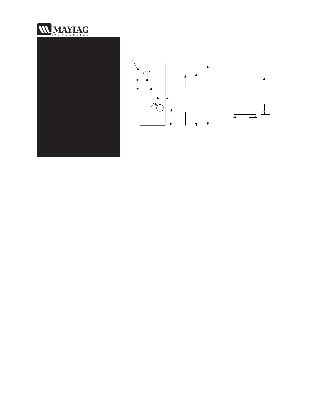
PRODUCT DIMENSIONS
ELECTRICAL CONN.
GAS INLET
Models
MDG30MC2
MDG30PC2
MDG30PNA
MDG30MNA
6"
15.2 cm
8"
20.3 cm
EXHAUST
DIAMETER
11 1/2"
29.2 cm
6"
15.2 cm
20 1/4"
51.4 cm
62 1/2"
158.8 cm
63"
160 cm
72"
182.9 cm
43"
109.2 CM
31 3/8"
79.7 cm
REAR VIEW TOP VIEW
PRODUCT SPECIFICATIONS
• Drive motor: 1/2 H.P. (.373 Kw)
• Air flow: 600 cubic feet (17 cubic meters) per minute.
• Amperage Draw: 9.8 amps (approximate).
• Heat source: 90,000 BTU/Hr. (22,680 kcal/hr.).
• Flush to side wall installation possible, 24" rear clearance suggested for ease of maintenance.
• Tumbler Capacity: 12.3 cu. ft. (.348 cu.m.)
• Tumbler Diameter: 30" (76.2 cm)
• Tumbler Depth: 30" (76.2 cm)
• Door Opening: 21 1/2" Dia. (54.61 cm)
• Weight: Crated: 550 lbs. (250 Kg)
Uncrated: 500 lbs. (227 Kg)
• Gas Inlet 1/2" I.D.
ELECTRICAL REQUIREMENTS
• 120 volts, 60 Hz single phase, (some 240 volts, 50 Hz models available for export).
• Individual branch circuit serving only the dryer is recommended.
• Minimum wire size required, awg. 12 with a 20 amp fuse or comparable circuit breaker. Copper
wire only.
• Dryer must be installed and grounded in accordance with National Electrical Codes and local
codes and ordinances.
COMMERCIAL MULTI LOAD DRYERS - MDG30, MC2, PC2, PNA, and MNA
6-107/02
EXHAUST REQUIREMENTS
Exhaust duct work should be designed and installed by a qualified professional. Improperly sized duct work will
create excessive back pressure which results in slow drying, increased use of energy, and shutdown of the burner by the
airflow (sail) switch, burner hi-limit chamber hi-heat protector thermostat.
Where possible, it is suggested to provide a separate (single) exhaust duct for each dryer.
CAUTION: IMPROPERLY SIZED OR INSTALLED EXHAUST DUCT WORK CAN
CREATE A POTENTIAL FIRE HAZARD.
CAUTION: DRYER MUST BE EXHAUSTED TO THE OUTDOORS.
The exhaust duct work should be laid out in such a way that the work travels as directly as possible to the outdoors with
as few turns as possible. The shape of the duct work
provided. Single or independent dryer venting is recommended.
is not critical so long as the minimum cross section area is
It is suggested that the use of 90° turns
The duct work should be smooth inside with no projections from sheet metal screws or other obstructions which will
collect lint. When adding ducts, the ducts to be added should overlap the duct which it is connected. ALL duct work
joints must be taped to prevent moisture and lint from escaping into the building. Additionally, inspection doors
should be installed at strategic points in the exhaust duct work for periodic inspection and cleaning.
IMPORTANT: When connecting duct work to the dryer exhaust duct, be sure that when screws are
used they
do not restrict the operation (both opening and closing) of the damper.
be avoided; use 30° or 45° angles instead.
NOTE: When the exhaust duct passes through a wall, ceiling, or roof made of combustible materials,
the opening must be 2-inches larger (all the way around) than the duct. The duct must be
centered within this opening.
To protect the outside end of horizontal duct work from the weather, a 90° elbow bent downward should be installed
where the exhaust exits the building. If the duct work travels vertically up though the roof, it should be protected from
the weather by using a 180° turn to point the opening downward. In either case, allow at least twice the diameter of the
duct between the duct opening and the nearest obstruction (i.e., roof of ground level).
IMPORTANT: DO NOT use screens or caps on the outside of opening of exhaust duct work.
IMPORTANT: Exhaust back pressure measured by a manometer at the dryer exhaust are must not
exceed 0.3 inches of water column (W.C.)
COMMERCIAL MULTI LOAD DRYERS - MDG30, MC2, PC2, PNA, and MNA
6-207/02
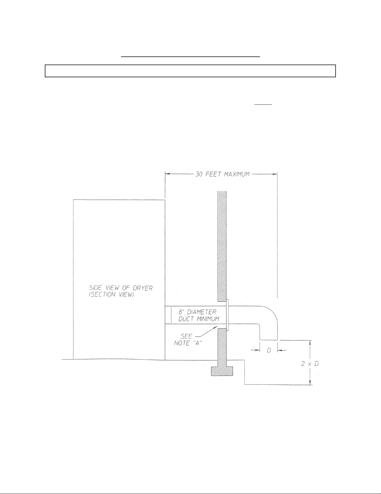
SINGLE DRYER VENTING
IMPORTANT: For exhaust duct runs over 30 feet a minimum diameter size of 10 inches must be used
HORIZONTAL VENTING
When horizontal single 8-inch venting is used, the duct work to the outlet cannot
below). This calculation of 30 feet compensates or allows for the use of a maximum of only one (1) elbow.
REMINDER - Stay below 0.3” WC back pressure.
Illus. A
exceed 30 feet (refer to Illus. A
HORIZONTAL SINGLE DRYER
VENTING 8 INCH DUCTING
NOTE A. OPENING MUST BE TWO (2) INCHES LARGER THAN THE DUCT (ALL THE
WAY AROUND). THE DUCT MUST BE CENTERED WITHIN THIS OPENING.
6-307/02COMMERCIAL MULTI LOAD DRYERS - MDG30, MC2, PC2, PNA, and MNA
 Loading...