

Maytag MDE28PDDGW, MDE28PRDGW Installation Instructions
INSTALLATION
INSTRUCTIONS
ORIGINAL INSTRUCTIONS
COmmeRCIAL He DRyeR
eLeCTRIC
INSTRUCTIONS
D’INSTALLATION
INSTRUCTIONS ORIGINALeS
SèCHe-LINGe He COmmeRCIAL
eLeCTRIqUe
INSTRUCCIONES
MDE28PD
DE INSTALACIÓN
INSTRUCCIONeS ORIGINALeS
SeCADORA He COmeRCIAL
eLéCTRICA
ISTRUZIONI
D’INSTALLAZIONE
ISTRUZIONI ORIGINALI
ASCIUGATRICe He COmmeRCIALe
eLeTTRICA
MDE28PN/PR
www.maytagcommerciallaundry.comW11311972B

TABLE OF CONTENTS
Page
Dryer Safety ............................................................................ 3
Dryer Disposal ........................................................................ 6
Tools & Parts .......................................................................... 7
Specications .......................................................................... 7
Dimensions/Clearances ........................................................ 8
Installation Requirements ..................................................... 9
Venting Requirements ......................................................... 11
Installing Leveling Legs, Payment Device,
and Coin Box ......................................................................... 14
Leveling ................................................................................ 15
Complete Installation .......................................................... 16
Reversing Door Swing (optional) ........................................ 17
Maintenance Instructions ................................................... 19
If You Need Assistance ....................................................... 19
Electronic Control Setup Instructions ............................... 20
Warranty ............................................................................... 25
TABLE DES MATIÈRES
Page
Sécurité de la Sécheuse ...................................................... 26
Mise au Rebut de la Sécheuse ............................................ 29
Outils et Pièces .................................................................... 30
Spécications ........................................................................ 30
Dimensions/Distances de Dégagement .............................. 31
Exigences D’installation ..................................................... 32
Exigences Concernant L’évacuation ................................... 34
Installation des Pieds de Nivellement, du Dispositif
dePaiement et de la Caisse à Monnaie .............................. 37
Mise à Niveau ......................................................................... 38
Fin de L’installation ............................................................. 39
Inversion du Sens D’ouverture de la Porte (Facultatif) ..... 40
Instructions D’entretien ...................................................... 42
En cas de Besoin D’assistance .......................................... 42
Instructions de Paramétrage
des Commandes Électroniques ........................................... 43
Garantie .................................................................................. 49
ÍNDICE
Página
Seguridad de la Secadora ................................................... 50
Desecho de la Secadora ...................................................... 53
Herramientas y Piezas ......................................................... 54
Especicaciones ................................................................... 54
Dimensiones y Espacios Libres ........................................... 55
Requisitos de Instalación .................................................... 56
Requisitos de Ventilación ................................................... 58
Instalación de las Patas Niveladoras, Dispositivo
dePagoyCaja de Monedas ............................................... 61
Nivelación .............................................................................. 62
Complete la Instalación ....................................................... 63
Cambio del Sentido de Apertura de la Puerta (Opcional) . 64
Instrucciones de Mantenimiento ....................................... 66
Si Necesita Asistencia ......................................................... 66
Instrucciones de Programación del Control Electrónico .. 67
Garantía ................................................................................ 73
INDICE
Pagina
Sicurezza Dell'asciugatrice .................................................. 74
Smaltimento Dell'asciugatrice ............................................. 77
Attrezzi e Parti .......................................................................78
Speciche .............................................................................. 78
Dimensioni/Spazi Minimi .................................................... 79
Requisiti per L'installazione ................................................. 80
Requisiti di Sato .................................................................. 82
Installazione dei Piedini di Messa in Piano,
del Dispositivo di Pagamento e Della Gettoniera ............... 85
Messa in Piano.......................................................................86
Completamento Dell'installazione ....................................... 87
Inversione Dell'apertura Dello Sportello (Opzionale) ......... 88
Istruzioni per la Manutenzione ............................................. 90
Come Richiedere Assistenza ...............................................90
Istruzioni di Congurazione Della Centralina Elettronica..91
Garanzia ................................................................................. 97
2
DRYER SAFETY
WARNING – RISK OF FIRE/FLAMMABLE MATERIALS
This is an additional safety alert symbol that alerts you to the risk of re.
FOR YOUR SAFETY
1. DO NOT USE OR STORE PETROL OR OTHER FLAMMABLE MATERIALS IN THIS APPLIANCE OR NEAR THIS APPLIANCE.
2. DO NOT SPRAY AEROSOLS IN THE VICINITY OF THIS APPLIANCE WHILE IT IS IN OPERATION.
3. DO NOT MODIFY THIS APPLIANCE.
3

DRYER SAFETY
IMPORTANT SAFETY INSTRUCTIONS
WARNING: To reduce the risk of re, electric shock, or injury to persons when using the dryer,
follow basic precautions, including the following:
■ Read all instructions before using the
dryer.
■ This dryer is intended only for drying
clothes and textiles that have been
washed in water. Do not use for any other
purpose.
■ Oil-affected items can ignite
spontaneously, especially when exposed
to heat sources such as a tumble dryer.
The items become warm, causing an
oxidation reaction in the oil. Oxidation
creates heat. If the heat cannot escape,
the items can become hot enough to catch
fire. Piling, stacking or storing oil-affected
items can prevent heat from escaping and
so creates a fire hazard.
■ If it is unavoidable that fabrics that
contain vegetable or cooking oil or that
have been contaminated by hair care
products be placed in a tumble dryer, they
should first be washed in hot water with
extra detergent – this will reduce, but not
eliminate the hazard.
■ Do not dry articles that have been
previously cleaned in, washed in, soaked
in, or spotted with petrol, dry-cleaning
solvents, other flammable, or explosive
substances as they give off vapors that
could ignite or explode.
■ Items that have been soiled with
substances such as acetone, alcohol,
petrol, kerosene, spot removers,
turpentine, waxes, and wax removers
should be washed in hot water with extra
detergent before being dried in the dryer.
■ Do not dry unwashed items in the dryer.
■ Do not use this dryer if industrial chemicals
have been used for cleaning. The
possible presence of residual quantities of
aggressive or decomposed chemicals in
the load may produce damage to the dryer
and harmful fumes.
■ Do not allow children to play on or in the
dryer. Close supervision of children is
necessary when the dryer is used near
children. Cleaning and user maintenance
shall not be made by children without
supervision. Children of less than 3 years
should be kept away unless continuously
supervised.
■ If the dryer is not heating, or appears to
be defective or damaged, do not use it.
Contact the owner.
■ Do not install or store the dryer where it will
be exposed to the weather.
■ Do not tamper with controls.
■ Clean dryer lint screen before or after each
load.
■ Do not use this dryer without the lint screen
in place.
■ Do not repair or replace any part of the
dryer or attempt any servicing unless
specifically recommended in this Use and
Care Guide or in published user-repair
instructions that you understand and have
the skills to carry out.
■ Fabric softeners, or similar products,
should be used as specified by the fabric
softener instructions.
■ Items such as foam rubber (latex foam),
shower caps, waterproof textiles, rubberbacked articles, and clothes or pillows
fitted with foam rubber pads should not be
dried in the tumble dryer.
■ The final part of a tumble dryer cycle
occurs without heat (cool-down cycle)
to ensure that the articles are left at a
temperature that ensures that the items will
not be damaged.
■ WARNING: Never stop a tumble dryer
before the end of the drying cycle unless all
items are quickly removed and spread out
so that the heat is dissipated. (Avoids risk
of spontaneous combustion).
■ WARNING: The appliance must not be
supplied through an external switching
device, such as a timer, or connected to a
circuit that is regularly switched on and off
by a utility.
■ In case of electrical supply failure, remove
the load quickly and spread it out to avoid
risk of spontaneous combustion.
■ Keep area around the exhaust opening and
adjacent surrounding areas free from the
accumulation of lint, dust, and dirt.
■ Ventilation openings in the base shall not
be obstructed by a carpet or similar object.
4

DRYER SAFETY
■ This appliance is intended, but not limited,
to be used in public areas.
■ This dryer is not intended for use by
persons (including children aged from 8
years and above) with reduced physical,
sensory, or mental capabilities, or lack
of experience or knowledge, unless they
have been given supervision or instruction
concerning use of the dryer by a person
responsible for their safety.
■ Before the dryer is removed from service
or discarded, remove the door to the dryer
compartment.
■ Do not reach into the dryer if the drum is
moving.
■ Opening the dryer door will stop the
function of the dryer.
■ When loading or re-loading the dryer,
avoid touching hot metal parts of the drum
(burn risk).
■ Remove all objects from pockets such as
lighters and matches.
■ If drum rotation is blocked due to trapped
textiles, disconnect the dryer from the
electrical supply before gently removing
the blockage.
■ If this is not possible due to the
construction of the appliance or its
installation, a disconnection with a locking
system in the isolated position shall be
provided.
■ Only authorized spare parts shall be used
in the event of failure.
■ This appliance incorporates an earth
connection for functional purposes only.
■ The dryer must not be installed behind
a lockable door, a sliding door or a door
with a hinge on the opposite side to that
of the tumble dryer, in such a way that a
full opening of the tumble dryer door is
restricted.
■ Exhaust air must not be discharged into
a flue which is used for exhausting fumes
from appliances burning gas or other fuels.
■ The fresh-air ventilation openings into
the room and into the dryer must not be
blocked or sealed.
■ Emergency stop control: After installation,
access to mains plug or disconnection
from mains supply via a double-pole switch
must be ensured at all times in order to
ensure immediate deactivation of the dryer
in case of emergency.
■ The interior of the dryer and dryer exhaust
vent should be cleaned periodically by
qualified service personnel.
■ See “Electrical Requirements” section in
“Installation Requirements” for earthing
instructions.
■ Adequate ventilation has to be provided to
avoid the back-flow of gases into the room
from appliances burning fuels, including
open fires.
■ The dryer shall be disconnected from its
power source during service and when
replacing parts.
■ See DIMENSIONS/CLEARANCES
section for minimum installation spacing
requirements.
■ IEC Load Capacity: 9.0 kg.
■ This dryer is not fitted with a supply cord
and a plug. Means for disconnection
from the supply mains having a contact
separation in all poles that provide
full disconnection under overvoltage
category III conditions must be provided,
otherwise means for disconnection must
be incorporated in the fixed wiring in
accordance with the wiring rules.
SAVE THESE INSTRUCTIONS
5
DRYER DISPOSAL
This appliance is marked according to the European directive 2012/19/EU on Waste Electrical and Electronic Equipment
(WEEE).
By ensuring this product is disposed of correctly, you will help avoid potential negative consequences for the environment
and human health, which could otherwise be caused by inappropriate waste handling of this product.
The symbol on the product, or on the documents accompanying the product, indicates that this appliance may not be
treated as household waste. Instead it shall be handed over to the applicable collection point for the recycling of electrical
and electronic equipment.
Disposal must be carried out in accordance with local environmental regulations for waste disposal.
For more detailed information about treatment, recovery and recycling of this product, please contact your local city ofce,
your household waste disposal service or the shop where you purchased the product.
MODEL NOMENCLATURE:
MDE – Maytag Dryer – Electric PN – Electronic Control – Non-Pay
## (e.g. 28) – Model Type Number PD – Electronic Control – Coin Drop Enabled
PR – Electronic Control - Card Ready
6
TOOLS & PARTS
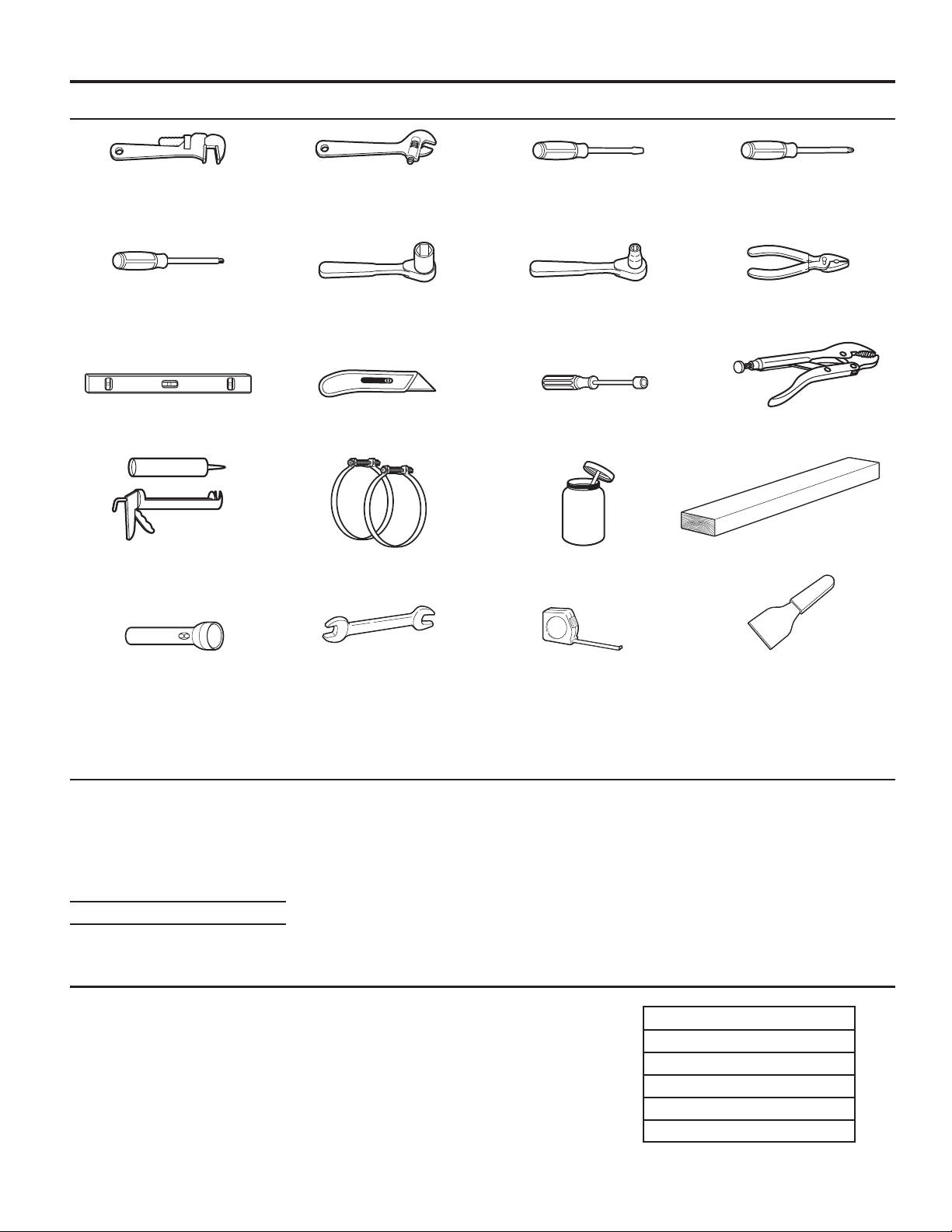
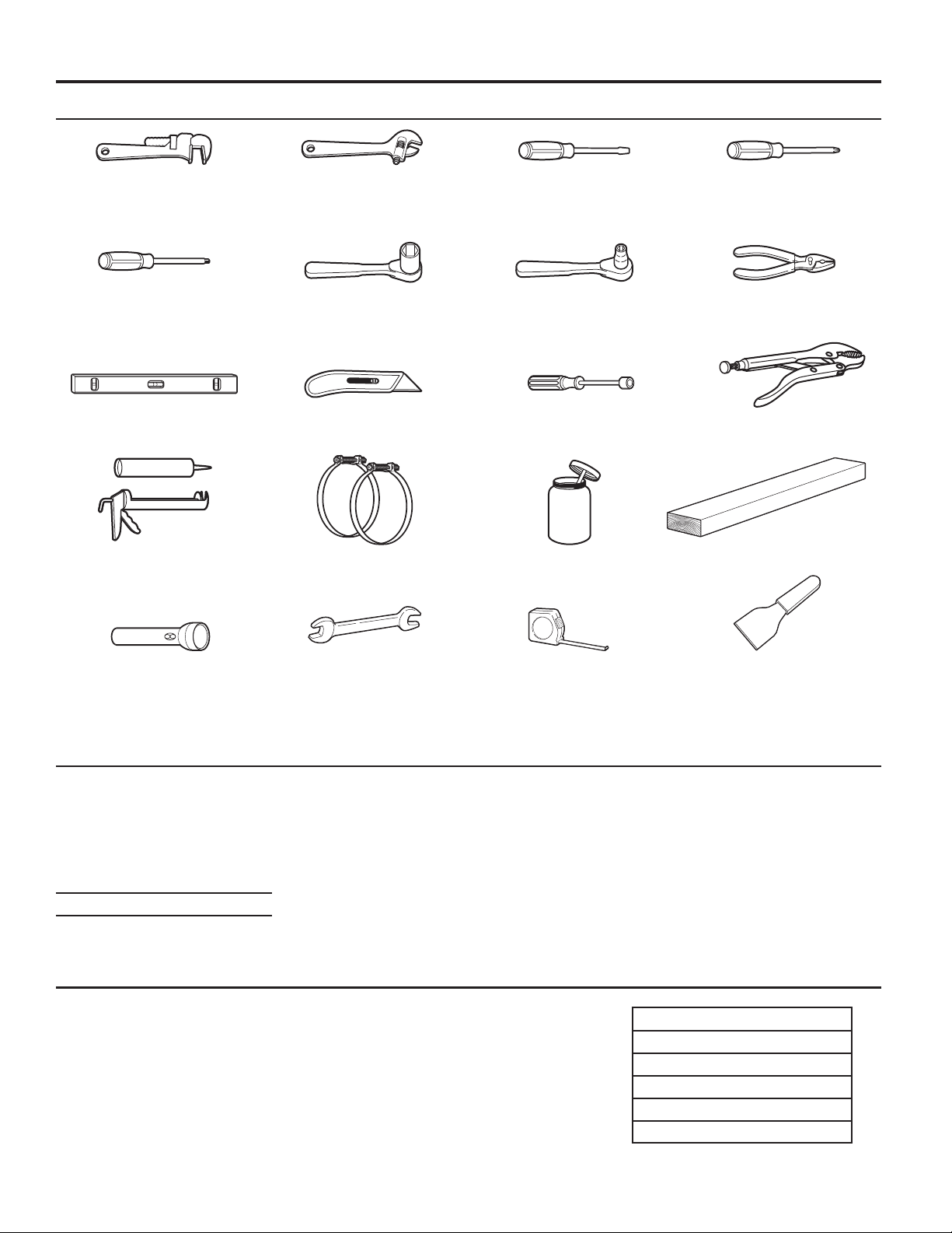
Tools Needed:
8" or 10" 8" or 10" Flat-blade screwdriver Phillips screwdriver
Pipe wrench Adjustable wrench
that opens to 1"
Torx T20† Security 1" Hex-head 5/16" Socket wrench Pliers
screwdriver or bit socket wrench (that open to 19/16")
Level Utility knife 1/4" Nut driver Locking pliers
Caulk gun and caulk Vent clamps Pipe-joint compound 27" Wood block
(for installing new exhaust vent) suitable for gas type
Flashlight (optional) 1" Open-end Ruler or measuring tape Putty knife
wrenches
Parts Supplied:
■ Foot boots (4)
■ Leveling legs (4)
■ PN/PR models: Card reader bezel, hardware
NOTE: The circuit diagram for this dryer is located inside the side panel, within the Tech Sheets.
Technical Specications:
220–240 V, 50 HZ. 4575 W
Total mass: 69 kg maximum
SPECIFICATIONSSPECIFICATIONS
These units are sold in multiple regions with different requirements for
measuring capacity. Below are a few of the valid forms of measure posted
on this product:
Dry Linen Capacity: A weight measure that reects a minimum threshold for
dry volume capacity that is needed for import tariff purposes.
IEC Capacity: The capacity measure that represents the maximum capacity
of dry linens and textiles which the manufacturer declares can be treated in a
specic cycle.
†TORX and T20 are trademarks of Acument Intellectual Properties, LLC.
Dry Linen Capacity
10.5 kg (23 lb)
IEC Capacity
9.0 kg (20 lb)
Sound Level
LpA: 58 dB(A) {kPa+/-10 dB(A)}
7
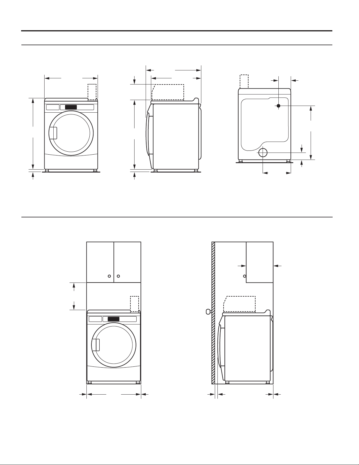
DIMENSIONS/CLEARANCES
(1")
736 mm
(1")
Dimensions
Front View Side View Back View
965 mm
(38")
25 mm
Clearances
686 mm
(27")
203 mm
(8")
921 mm
1
/4")
(36
25 mm
Recessed Front View
(29")
695 mm
(271/4")
Closet Side View
358 mm
(14")
159 mm
(6
715 mm
(28
89 mm
1
/2")
(3
1
/4")
1
/8")
381 mm
(15")
0 mm
(0")
25 mm
(1")
356 mm
(14")
0 mm
(0")
8
Location
Your dryer can be installed in a basement, laundry room,
or recessed area.
Companion appliance location requirements should also
be considered.
IMPORTANT: Do not install or store the dryer where it
will be exposed to the weather. Proper installation is your
responsibility.
You will need:
■ A level floor with a maximum slope of 25 mm (1") under
entire dryer. Installing the dryer on soft floor surfaces,
such as carpets or surfaces with foam backing, is not
recommended.
■ A sturdy and solid floor to support the dryer with a total
weight (load) of 204 kg (450 lbs).
Installation clearances
■ The location must be large enough to allow the dryer door
to be fully opened.
■ Additional spacing should be considered for ease of
installation and servicing. The door opens more than 180°.
■ Additional clearances might be required for wall, door,
and floor moldings.
■ Additional spacing of 25 mm (1") on all sides of the dryer
is recommended to reduce noise transfer.
■ Companion appliance spacing should also be considered.
INSTALLATION REQUIREMENTS
Recessed Area and Closet Installation Instructions
This dryer may be installed in a recessed area or closet. The
dryer must not be installed behind a lockable door, a sliding door,
or a door with a hinge on the opposite side to that of the dryer
in such a way that a full opening of the dryer door is restricted.
For recessed area and closet installations, minimum clearances
can be found on the warning label on the rear of the dryer or in
“Dimensions/Clearances.”
The installation spacing is in millimeters and is the minimum
allowable. Additional spacing should be considered for ease
of installation, servicing, and compliance with local codes
and ordinances.
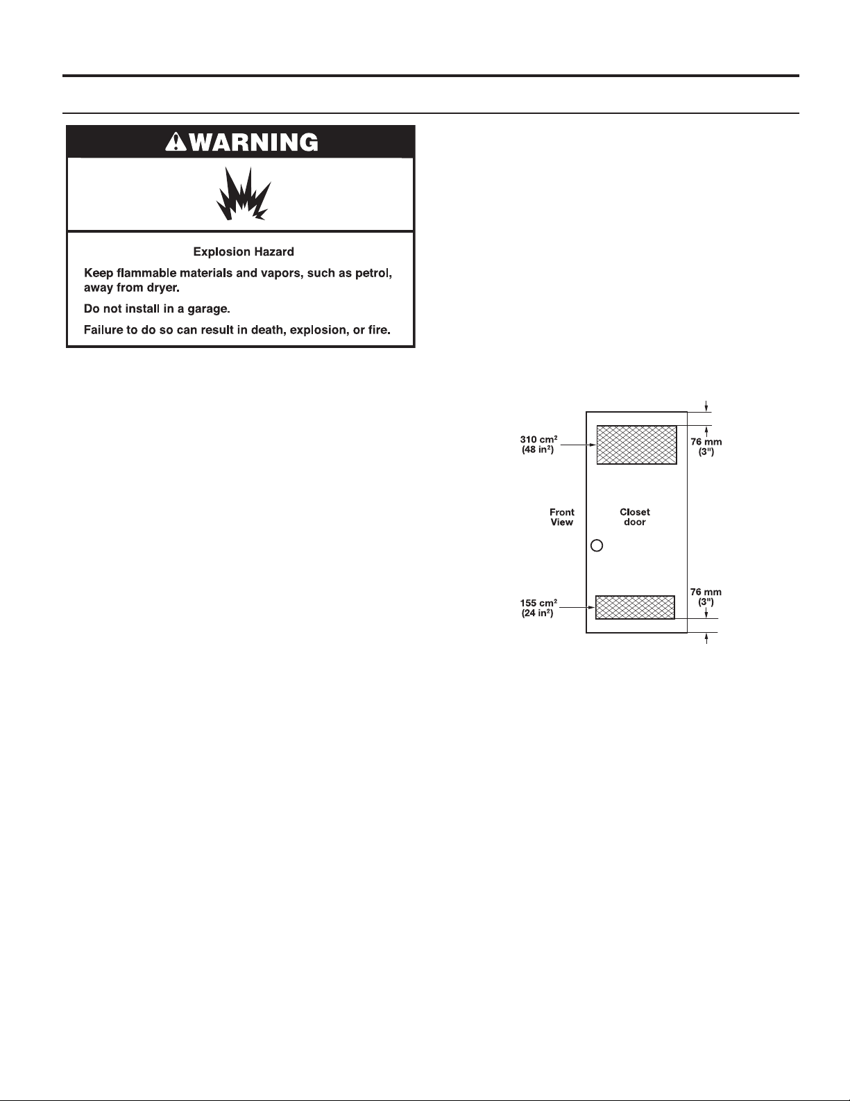
If closet door is installed, the minimum unobstructed air
opening in the top and bottom of the door shall be as depicted in
the diagram below. Louvered doors with equivalent air openings
are acceptable.
The dryer must be exhausted outdoors.
NOTE: For installation in Australia and New Zealand, refer
to AS/NZS 5601.1 for ventilation requirements.
NOTE: This dryer is not intended to be placed on top
of a washer.
9
INSTALLATION REQUIREMENTS
Electrical Requirements
This dryer is supplied without an electric cord and plug.
It must be connected by a competent electrician to a singlephase electricity supply at the voltage shown on the dataplate,
using a suitable xed wiring installation in accordance with local
and national wiring regulations.
■ A 3-wire circular cord of minimum conductor size 4 mm
cross-section area should be used.
■ A 25 A (minimum) supply fuse should be used, and a switch
having a contact separation in both poles that provides full
disconnection under over-voltage category III conditions
must be incorporated into the fixed wiring in accordance
with local wiring regulations. The dryer should be positioned
so that the disconnection switch is clearly visible and easily
accessible to the user. This disconnection switch also
provides the function of an emergency stop control
for the user.
■ A cord clamp bush is provided on the dryer, and should
be tightened on completion of wiring. The electrical mains
terminals are located behind the small rear access panel
(terminal block cover), and connections should be made
in accordance with the terminal markings. Remember to
replace the terminal access panel (terminal block cover).
NOTE: In accordance with the European EMC Directive
(2014/30/EU), the maximum electricity supply system
impedance to which the electric dryer should be connected
is declared to be 0.054 Ohm + j0.034 Ohm.
NOTE: Electrical safety standards: The manufacturer has
chosen compliance with IEC/EN.60335 standards as the
most appropriate for this product.
2
This is a 3-wire appliance which must be earthed.
If codes permit and an additional earth bond wire is used,
it is recommended that a qualied electrician determine that
the earth bond path is adequate.
Recommended Earthing Method
It is your responsibility to contact a qualied electrical installer
to ensure that the electrical installation is adequate and in
conformance with all local codes and ordinances.
10
VENTING REQUIREMENTS
NOTES:
■ Although usually each single-load dryer should have
an unobstructed outdoor air opening of 24 in2 (154 cm2)
(based on 1 in2 [6.5 cm2] per 1,000 Btu [252 kcal]), common
makeup air openings are also acceptable. Set up common
openings so the makeup air is distributed equally to all
of the dryers. Keep in mind that the coverage area must
be increased by 33% to account for the use of registers
or louvers over the openings. Also, makeup air openings
should not be installed near the location where exhaust
vents exit the building.
■ If using an existing vent system, clean lint from entire length
of the system and make sure exhaust hood is not plugged
with lint. Replace plastic or metal foil vents with rigid metal
or flexible metal vents. Review “Vent System Chart” and,
if necessary, modify existing vent system to achieve best
drying performance.
WARNING: To reduce the risk of re, this dryer MUST BE
EXHAUSTED OUTDOORS.
IMPORTANT: Observe all governing codes and ordinances.
■ Following these venting requirements will minimize ducting
air noise.
■ Exhaust air must not be discharged into a ue for
exhausting fumes from appliances burning gas or other
fuels, including open res (i.e., available airow into
the room should match airow out from the room).
■ Adequate ventilation must be provided to avoid the back
ow of gases into the room from appliances burning other
fuels, including open res.
■ Dryer exhaust must not be connected into any gas vent,
chimney, wall, ceiling, attic, crawl space, or a concealed
space of a building. Only rigid or exible metal vent shall
be used for exhausting.
■ Do not use an exhaust hood with a magnetic latch.
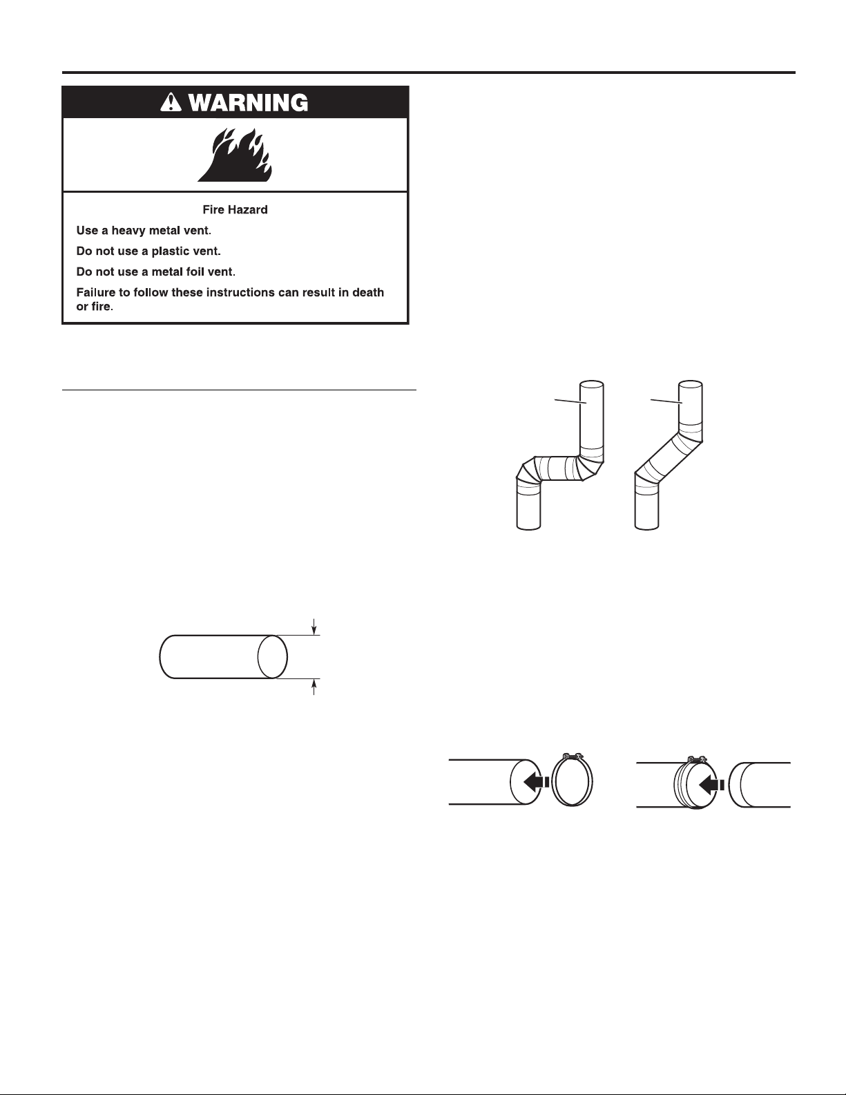
102 mm
(4")
102 mm (4") heavy, metal exhaust vent
■ Only a 102 mm (4") heavy, metal exhaust vent and clamps
may be used.
■ Do not use plastic or metal foil vent.
Elbows:
■ 45° elbows provide better airow than 90° elbows.
Good
■ Plan installation to use the fewest number of elbows
Better
and turns.
■ Allow as much room as possible when using elbows
or making turns. Bend vent gradually to avoid kinking.
■ Vent outlet is located at the center of the bottom dryer back.
■ The vent can be routed up, down, left, right, behind the
dryer, or straight out the back of the dryer.
Clamps:
■ Use clamps to seal all joints.
■ Exhaust vent must not be connected or secured with
screws or other fastening devices that extend into interior
of duct and catch lint. Do not use duct tape.
Rigid metal vent:
■ Recommended for best drying performance and to avoid
crushing and kinking.
Flexible metal vent: (Acceptable only if accessible to clean)
■ Must be fully extended and supported in nal dryer location.
■ Remove excess to avoid sagging and kinking that may
result in reduced airow and poor performance.
■ Do not install in enclosed walls, ceilings, or oors.
■ The total length should not exceed 2.4 m (7
■ An exhaust hood should cap the vent to keep rodents and
insects from entering the building.
3
⁄4 ft).
11
VENTING REQUIREMENTS
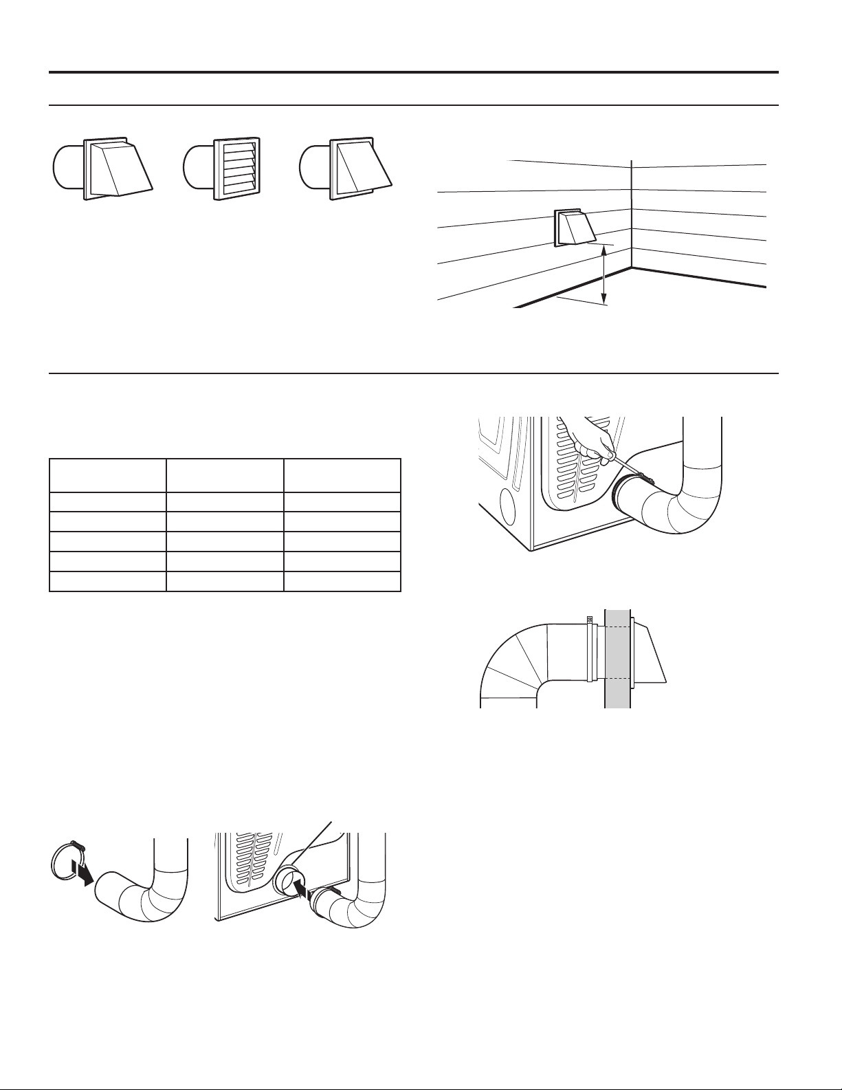
Vent Hoods
102 mm (4") Diameter Exhaust Hoods
Box hood Louvered hood Angled hood
Vent System Length
Maximum Vent Length/Vent Connection
Maximum length of vent system depends upon the type of vent
used, number of elbows, and type of exhaust hood.
Vent System Chart (Rigid Metal Vent)
No. of 90˚ Turns
0 39.6 m (130 ft) 39.3 m (129 ft)
1 38.1 m (125 ft) 36.3 m (119 ft)
2 35.1 m (115 ft) 33.2 m (109 ft)
3 32.3 m (106 ft) 30.5 m (100 ft)
4 29.9 m (98 ft) 28.0 m (92 ft)
For vent systems not covered by the “Vent System Chart,”
see your parts distributor.
Provision must be made for enough air for combustion and
ventilation. (Check governing codes and ordinances.) See
“Recessed Area and Closet Installation Instructions” in the
“Location” section.
A 102 mm (4") outlet hood is preferred. However, a 64 mm (21⁄2")
outlet exhaust hood may be used. A 64 mm (21⁄2") outlet creates
greater back pressure than other hood types. For permanent
installation, a stationary vent system is required.
Connect Vent
1. If connecting to existing vent, make sure the vent is clean.
2. Using a 102 mm (4") clamp, connect vent to exhaust outlet in
dryer.
Box and
Louvered Hood
Angled Hood
Vent collar
Exhaust hood must be at least 305 mm (12") from the ground
or any object that may be in the path of the exhaust (such as
owers, rocks, bushes, or snow).
305 mm min.
12" min.
(12")
(305 mm)
3. Tighten hose clamp with Phillips screwdriver.
4. Make sure the vent is secured to exhaust hood with
a 102 mm (4") clamp.
5. Move dryer into nal position. Do not crush or kink vent.
Make sure dryer is level.
NOTE: Do not remove vent collar.
12
VENTING REQUIREMENTS
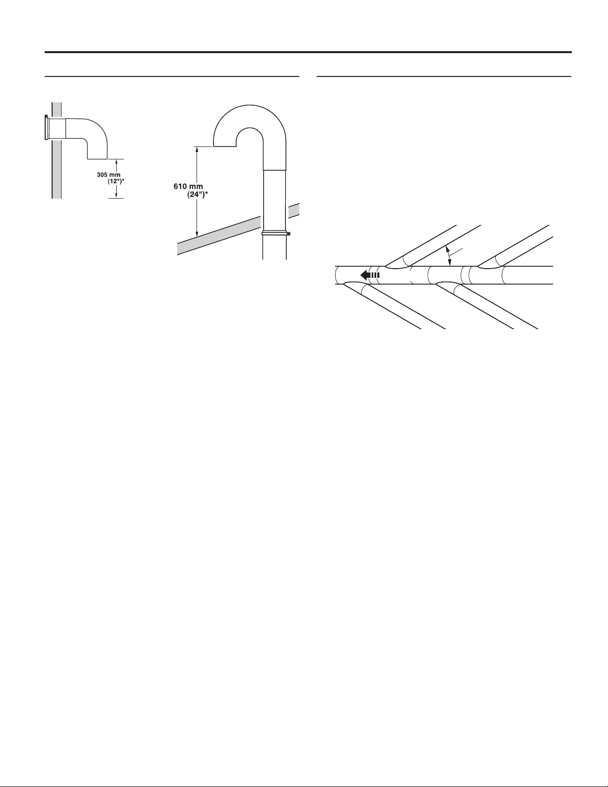
If an Exhaust Hood Cannot Be Used Multiple Dryer Venting
The outside end of main vent should have a sweep elbow
directed downward.
minimum
minimum
A main vent can be used for venting a group of dryers. The
main vent should be sized to remove 5663 l/minute (200 CFM)
of air per dryer. Large-capacity lint screens of proper design
may be used in main vent if checked and cleaned frequently.
The room where the dryers are located should have make-up
air equal to or greater than CFM of all the dryers in the room.
A Back-draft Damper Kit is available from your distributor and
should be installed in the vent of each dryer to keep exhausted
air from returning into dryers and to keep exhaust in balance
within main vent. Unobstructed return air openings are required.
Each vent should enter the main vent at an angle pointing in
the direction of the airow. Vents entering from the opposite
side should be staggered to reduce the exhausted air from
interfering with the other vents.
* Minimum clearance above
any accumulation of snow,
ice, or debris such as leaves
If main vent travels vertically through the roof, rather than
through wall, install a 180° sweep elbow on end of vent at least
610 mm (2 ft) above surface of roof.
The opening in wall or roof shall have a diameter 13 mm (1⁄2")
larger than vent diameter. Vent should be centered in opening.
Do not install screening over end of vent for best performance.
30˚ maximum
Air ow
The maximum angle of each vent entering the main vent should
be no more than 30°.
Keep air openings free of dry-cleaning uid fumes. Fumes
create acids which, when drawn through the dryer heating
units, can damage dryers and items being dried.
A clean-out cover should be located on the main vent for
periodic cleaning of the vent system.
13
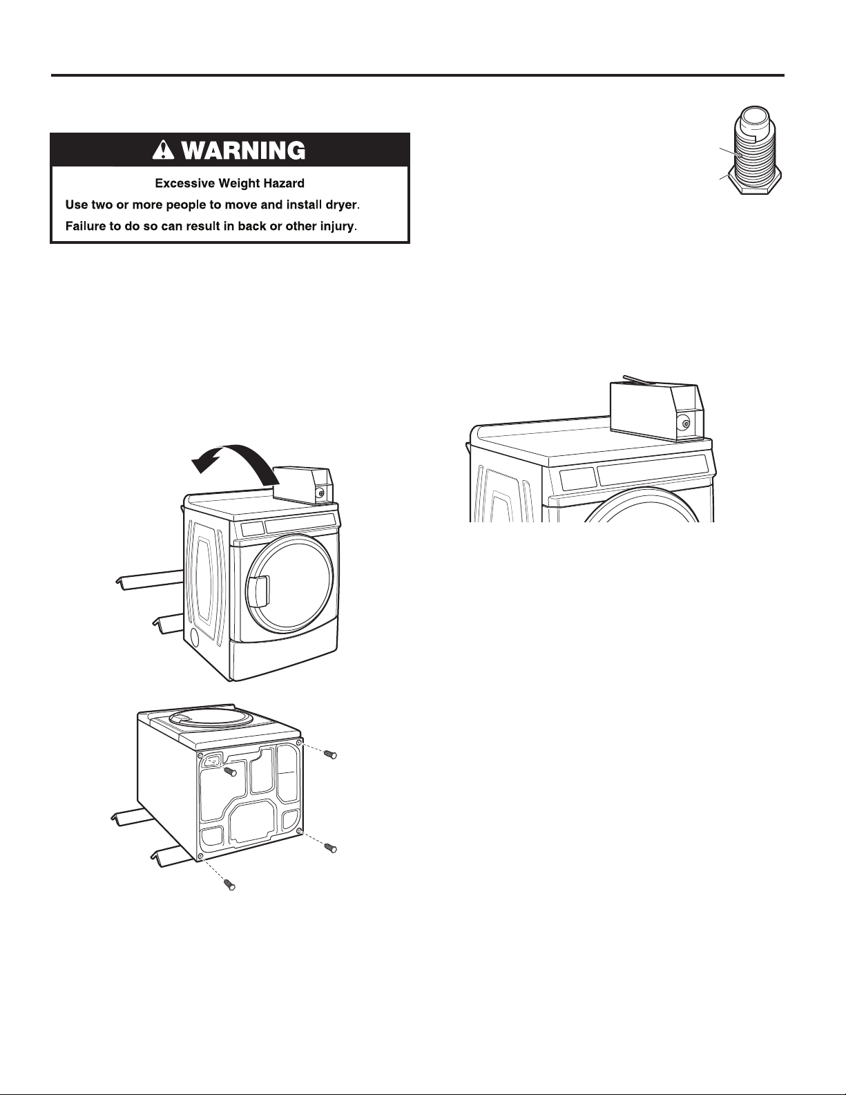
INSTALLING LEVELING LEGS, PAYMENT DEVICE, AND COIN BOXINSTALLING LEVELING LEGS, PAYMENT DEVICE, AND COIN BOX
The payment device, control panel lock and key, as well as the
coin box lock and key are not included, but are available from
the usual industry sources.
1. Prepare dryer for leveling legs
NOTE: Slide dryer onto cardboard or hardboard before moving
to avoid damaging oor covering.
Using two or more people, move dryer to desired installation
location.
Take tape off front corners of dryer. Open dryer and remove
the literature and parts packages. Wipe drum interior with damp
cloth to remove any dust.
Take two cardboard corners from the dryer carton and place
them on the oor in back of the dryer. Firmly grasp body of the
dryer and gently lay it on its back on the cardboard corners.
2. Screw in leveling legs
Examine leveling legs and nd diamond
marking. Screw legs into leg holes by
hand. Use an adjustable wrench or
25 mm (1") hex-head socket wrench to
nish turning legs until diamond marking
is no longer visible. Then t a covered foot
boot over each leg foot. A longer leveling foot
(Part Number 279810) is available if needed
on extremely sloped oors.
To protect the oor, use a large piece of cardboard from the
dryer carton. Stand dryer up on the cardboard. Slide the dryer
until it is close to its nal location. Leave enough room for
electrical connection and to connect the exhaust vent.
3. Install payment device and coin box
Remove the service door of the meter case by lifting it up
at the back. If applicable, install the money-accepting device.
(Refer to manufacturer’s instructions for proper installation.)
Diamond
marking
Foot
Replace the meter case service door. Put the coin vault with
lock and key in the meter case opening.
Remove cardboard or hardboard from under dryer. Adjust the
legs of the dryer up or down until the dryer is level.
14
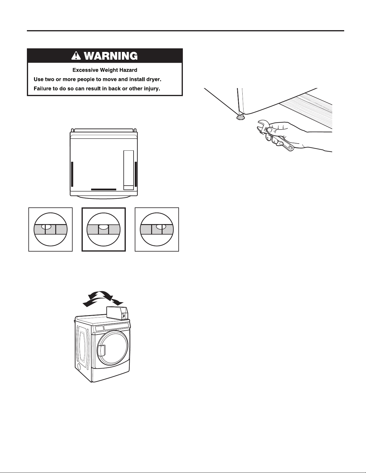
LEVELING
Leveling your dryer properly reduces excess noise and vibration.
1. Remove cardboard from beneath dryer. Place a level on top
edges of dryer, checking each side and front. If not level, tip
dryer and adjust feet up or down as shown in Steps 3 and 4,
repeating as necessary.
3. If dryer is not level, remove the rubber boot if used; then use
an adjustable wrench or 25 mm (1") hex-head socket wrench
to turn legs until adjustment is completed. Check levelness of
dryer after all feet are rmly touching the ground and the level
shows dryer top to be level front to back and side to side.
HELPFUL TIP: You may want to prop up front of dryer
about 102 mm (4") with a wood block or similar object
that will support weight of dryer.
4. When dryer is level and all four feet are rmly in contact
with the oor, use a 25 mm or (1") open-end or adjustable
wrench to turn nuts on leveling feet tightly against dryer
cabinet.
HELPFUL TIP: You may want to prop dryer with wooden
block.
Not Level LEVEL Not Level
2. Grip dryer from top and rock back and forth, making sure all
four feet are rmly on oor. Repeat, rocking dryer from side
to side. If dryer rocks, go to Step 3 and adjust leveling feet.
If all four feet are in rm contact with oor, go to Step 4.
15
COMPLETE INSTALLATION
1. Check the electrical requirements. Be sure that you have
the correct electrical supply and the recommended earthing
method. See “Electrical Requirements.”
2. Check that all parts are now installed. If there is an extra part,
go back through the steps.
3. Check that you have all of your tools.
4. Dispose of/recycle all packaging materials.
WARNING
Electric Shock Hazard
This dryer must be earthed.
Securely tighten all electrical connections.
Failure to do so can result in death, fire, or
electric shock.
5. Switch on power supply.
6. Check dryer operation. Using a full heat cycle, let the dryer
run for at least ve minutes. Dryer will stop when time is
used up.
NOTE: Dryer door must be closed for dryer to operate.
When door is open, dryer stops, but timer continues to run.
To restart dryer, close door and press cycle keypad.
16
REVERSING DOOR SWING (OPTIONAL)
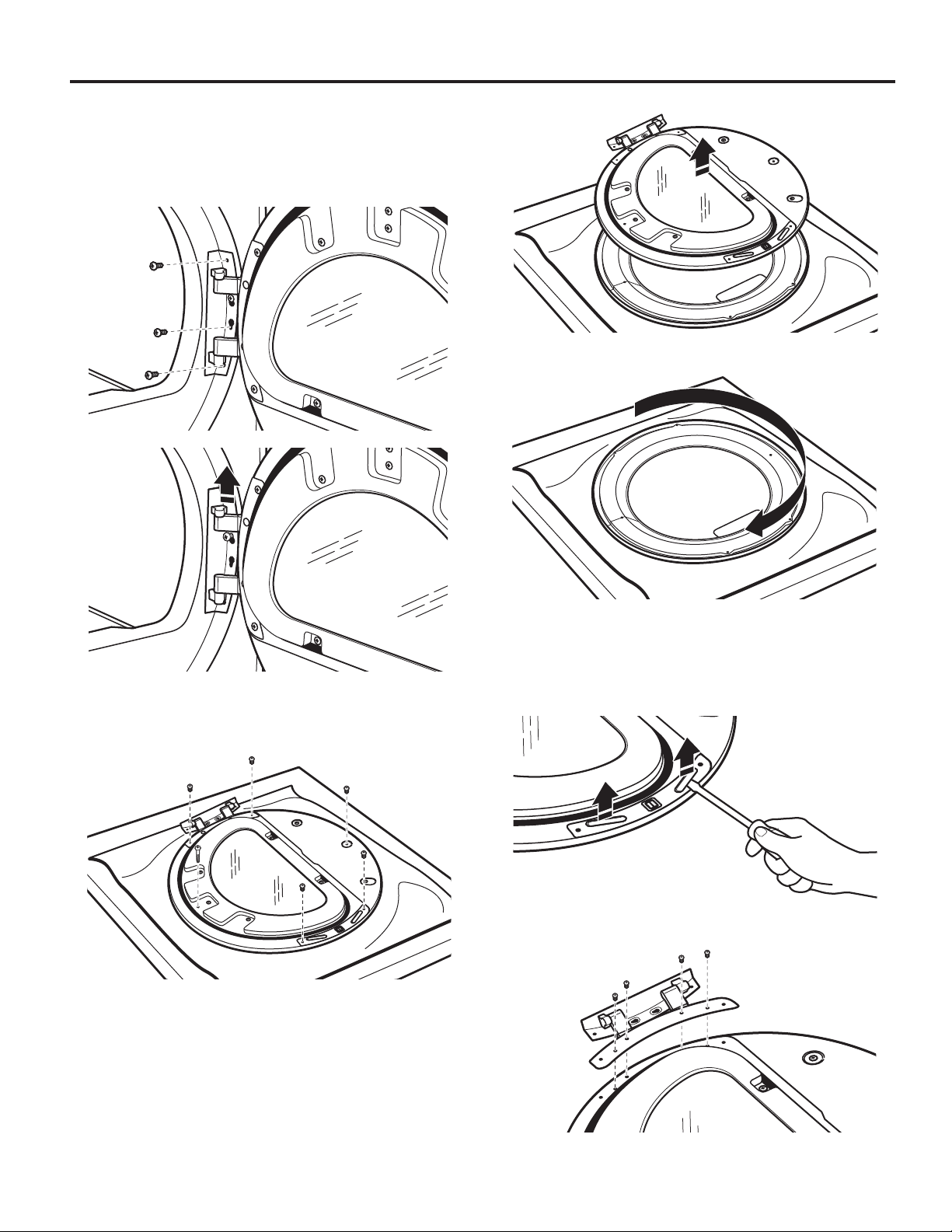
Remove the Door Assembly
1. Place a towel or soft cloth on top of dryer or workspace
to avoid scratching of the surface.
2. Remove 3 of the 4 screws that hold the door hinge on the
front panel of the dryer. Partially loosen the remaining screw
with keyhole opening and lift the door off the screw.
4. Lift the inner door assembly off outer door assembly.
5. Rotate outer door 180°.
3. Lay the door assembly on a previously prepared at surface
with the inside (inner door assembly) facing up, and remove
6 Phillips-head screws to release outer door assembly from
inner door assembly.
NOTE: It is important that you remove only 6 indicated screws.
Reverse Hinge
1. Use a small at-blade screwdriver to remove 2 plug strips
from the inner door. Slide the head of the screwdriver under
the plugs, without scratching inner door surface, and lift
up strip.
2. Remove the 4 screws that attach to inner door hinge.
17
REVERSING DOOR SWING (OPTIONAL)
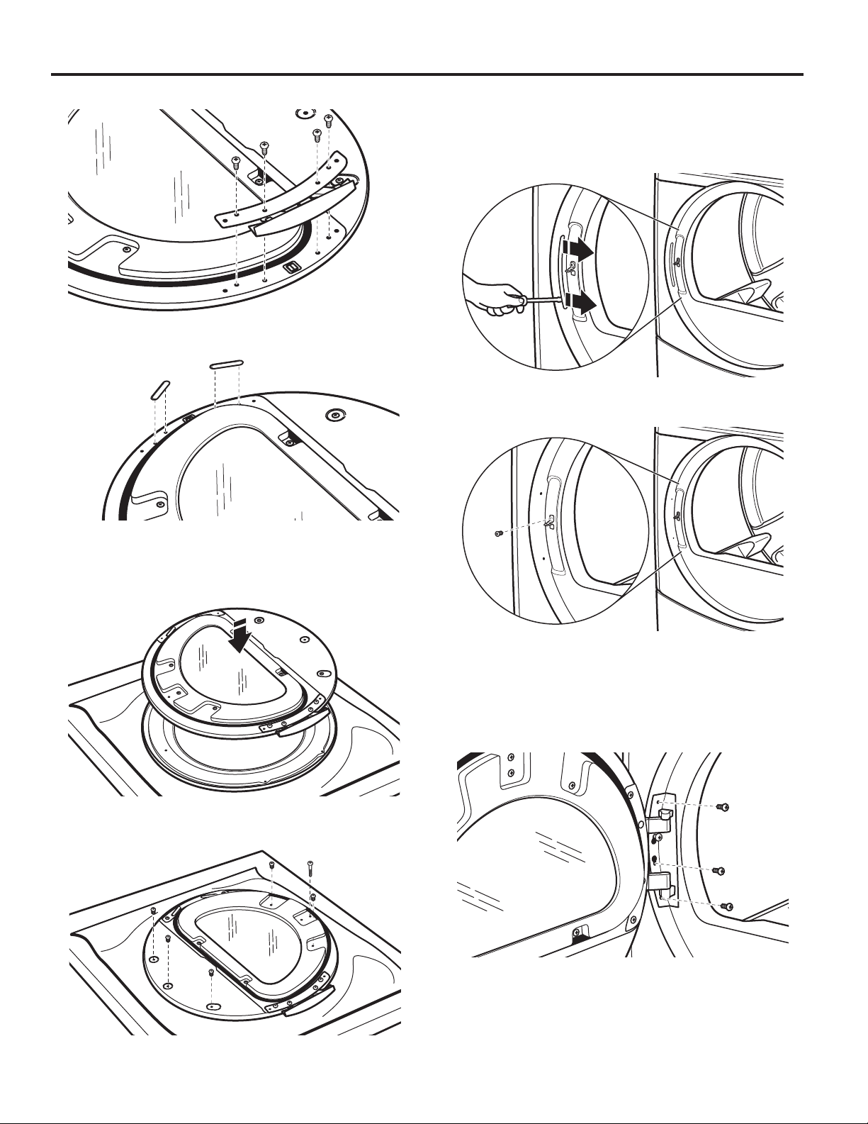
3. Move hinge to other side. Reinstall 4 screws.
4. Reinstall plug strips on opposite side of the inner door.
Reverse the Strike
1. Use a small at-blade screwdriver to remove plug strip from
the dryer door opening. Slide the head of the screwdriver
under the plugs, without scratching dryer surface, and lift
up strip.
2. Remove the strike using a Phillips screwdriver.
5. Check for ngerprints on the glass. Clean if necessary.
Replace the Door Assembly
1. Place the inner door assembly inside the outer door
assembly.
2. Reassemble the inner and outer door assemblies with the
6 screws.
3. Insert strike on the opposite side.
Reinstall the Door
1. Partially insert the third screw from the top; then slide the
hinge onto this screw while hooking the hinge into the front
panel hole. Reattach door to dryer front panel with the
remaining 3 screws.
18
2. Check for ngerprints on the glass. Clean if necessary.
3. Close door and check that it latches securely.

MAINTENANCE INSTRUCTIONS
■ Clean lint screen before and after each cycle.
■ Removing accumulated lint:
From inside the dryer cabinet:
Lint should be removed every 2 years,
or more often, depending
on dryer usage. Cleaning should
be done by a qualied person.
From the exhaust vent:
Lint should be removed every 2 years,
or more often, depending
on dryer usage.
Direct all requests for service to the Maytag Commercial
Laundry Distributor that sold the appliance.
When calling, please know the purchase date and the
complete model and serial number of your appliance. This
information will help us to better respond to your request.
If dryer does not operate, check the following:
■ Electrical supply is connected.
■ Circuit breaker is not tripped or house fuse is
not blown.
■ Door is closed. Listen closely to hear the door switch
activate.
■ Cycle selection keypad has been pushed firmly and display
shows cycle time.
IF YOU NEED ASSISTANCE
19
ELECTRONIC CONTROL SETUP INSTRUCTIONS
PRICE
IMPORTANT
Electrostatic Discharge (ESD)
Sensitive Electronics
ESD problems are present everywhere. ESD may damage
or weaken the electronic control assembly. The new control
assembly may appear to work well after repair is nished,
but failure may occur at a later date due to ESD stress.
■ Use an anti-static wrist strap. Connect wrist strap to
green earth connection point or unpainted metal in the
appliance.
-OR-
Touch your nger repeatedly to a green earth connection
point or unpainted metal in the appliance.
■ Before removing the part from its package, touch the
anti-static bag to a green ground connection point or
unpainted metal in the appliance.
■ Avoid touching electronic parts or terminal contacts;
handle electronic control assembly by edges only.
■ When repackaging failed electronic control assembly in
anti-static bag, observe above instructions.
General User Information
“OUT OF ORDER” SHOWING IN DISPLAY –
indicates the dryer is inoperative. Diagnostic or failure code
will follow the scrolling message.
“0 MINUTES” SHOWING IN DISPLAY – This indicates the
cycle is complete and the dryer cannot be operated. Coins
dropped or debit inputs during this condition will be stored in
escrow but cannot be used until normal operation is restored
by opening and closing the door. If a door switch has failed,
it must be replaced before normal operation can be restored.
COLD START (Initial rst use) – Dryer is programmed at the
factory as follows:
45 minutes dry time for PN/PR models; 5 minutes per coin for
PD models.
$1.50 dry price (xed cycle with top off – PD Models)
$0.00 dry price (xed cycle – PN/PR Models)
WARM START (after power failure) – A few seconds after
power is restored, if a cycle was in progress at the time of the
power failure, “RESELECT CYCLE” will ash in the display.
This indicates a fabric setting keypad needs to be pressed
to restart dryer.
PRICING – After the door is opened and then closed following
the completion of a cycle, the display indicates the cycle price
(unless set for free operation). As coins are dropped or debit
inputs arrive, the display will change to lead the user through
the initiation of a cycle.
There are four (4) types of dryer pricing:
Fixed “Vend” Pricing
A dryer set up for “Fixed Cycle” operation can only accept
additional time accumulated by increments equal to the length
of a complete dry cycle. A maximum of 75 minutes may be
purchased; no additional credit is given with 75 minutes in
the display.
Accumulator Pricing
If the price is set to one coin 1, then accumulator pricing
is in effect. Cycle time can be purchased one coin at a time
(PD models) up to the maximum time of 75 minutes.
20
This condition
Fixed Cycle With Top Off Pricing
A dryer set to offer “Top Off” capability will allow time to be
added to an existing dry cycle in increments equal to the
number of minutes of dry time per coin (coin 1), up to 75
minutes, regardless of the cost required to start the dryer. No
credit is given for coins or debit inputs entered when the control
is displaying 75 minutes.
PN Models Set Up as PR: In Enhanced Debit Mode, the top
off price can be set independently (see VALUE OF COIN 2),
and the top off time is calculated according to the following
equation:
Hundredth increment offset is not applied to top off purchases.
PN/PR Models – The factory has preset the cycle price to zero.
When this happens, “SELECT CYCLE” will appear rather than
a cycle price. Any cycle started as a free cycle will automatically
terminate when the door is opened.
DEBIT CARD READY – This dryer has a control that is debit
card ready, but the dryer is not.
top off price
full-cycle price
top off time
=
full-cycle length
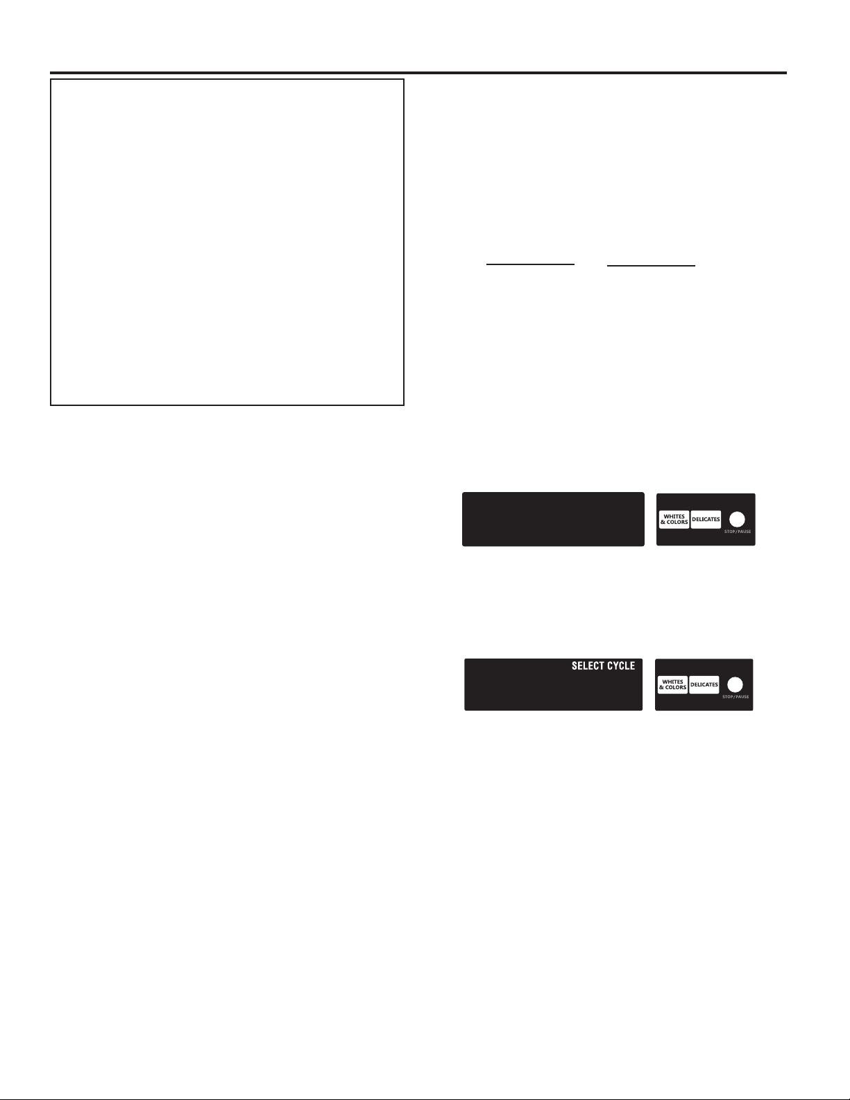
Display
After the dryer has been installed and plugged in, the display
will show “0 minutes.”
PD Models
1.50
Once the dryer has been plugged in and the dryer door opened
and closed, the display will show the vent price. PN/PR models
are factory preset for free cycles; the display will ash “SELECT
CYCLE.”
PN/PR Models
Control Setup Procedures
IMPORTANT: Read all instructions before operating.
The fabric setting keypads along with the digital display
are used to set up the dryer controls. The display can contain
4 numbers and/or letters and a decimal point. These are used
to indicate the setup codes and related code values available
for use in programming the dryer.
How to Use the Keypads to Program the Controls
1. The WHITES AND COLORS keypad is used to adjust the
values associated with setup codes. Pressing the keypad
will change the value by increments. Rapid adjustment is
possible by holding down the keypad.
2. The DELICATES keypad will advance the display through
the setup codes. Pressing the keypad will advance the
display to the next available setup code. Holding down
the DELICATES keypad will automatically advance through
the setup codes at a rate faster than 1 per second.
3. The STOP/PAUSE keypad is used to select or deselect
options.
ELECTRONIC CONTROL SETUP INSTRUCTIONS
Start Operating Setup
■ PD Models: Insert service door key, turn, and lift to remove
service door.
■ PN/PR Models: Remove the AA1 jumper from the control
board (see procedure below) or use the Service Access
Code below. Once the debit card reader is installed
(according to the reader manufacturer’s instructions), the
setup mode can be entered by inserting a manual setup
card (supplied by the reader manufacturer) into the card
slot. If manual setup card is not available, manual setup
mode cannot be entered. However, diagnostic mode can be
entered by removing connector AA1 on the circuit board.
IMPORTANT: The console must not be opened unless
power is rst removed from the dryer. To access connector
AA1:
Unplug dryer or disconnect power.
g
Open console, disconnect plug on AA1, close console.
g
Plug in dryer or reconnect power.
g
■ PN/PR Models Equipped with Programming Switch: Insert
access panel key and turn counterclockwise.
■ PN/PR Models with Gen. 2 Debit Card Reader: Once a Gen.
2 debit card reader is installed (according to the reader
manufacturer’s instructions), the setup mode can only be
entered by inserting a manual setup card (supplied by the
reader manufacturer) into the card slot.
■ If manual setup card is not available, only diagnostic mode
can be entered.
■ The alternative Service Access Code to enter set-up mode
is to press the following keypads in this sequence: Left
keypad, Right keypad, Left keypad, Right keypad, and Right
keypad.
NOTE: This dryer is preset at the factory and does not require
any programming. However, if you want to change the settings,
follow the “Setup Codes” guide below. PD models require a
payment system or OPL kit to be installed prior to operation.
■ PD units are pre-set at the factory for xed cycle price with
top off.
■ PN/PR units are pre-set for xed cycle operation so they
can be run without payment.
Setup Codes
■ The DELICATES keypad will advance you from code
to code.
■ The WHITE AND COLORS keypad will change the code
value.
■
The STOP/PAUSE keypad will select or deselect options.
PN/PR MODELS: The setup codes are the same as for the PD
models except where noted.
The setup code is indicated by the one or two left-hand
characters. The setup code value is indicated by the two or
three right-hand characters.
NOTE: The rst line of each code indicates the factory default.
Code Explanation
6 06 REGULAR CYCLE PRICE
6 06 Represents the number of quarters (coin 1) needed to
start the dryer; may adjust from 0–39. (See b.xx setup
for VALUE OF COIN 1.) Advance from 0–39 by pressing
the WHITES AND COLORS keypad. Factory default of
6 x coin 1.
6 00 PN/PR MODELS ONLY: Factory default of 6 00, or 0
coins.
• Press the DELICATES keypad once to advance
to next code.
7 05 REGULAR DRY TIME
7 05 PD MODELS: Represents the number of minutes
per coin one (coin 1).
Factory default of 5 minutes per coin.
Example: 6 coins x 5 minutes = 30 minutes.
By pressing the WHITES AND COLORS keypad,
value adjusts from 1–75 minutes.
7 45 PN/PR MODELS: Represents the cycle length for free
cycles. Example: “7 45” = 45 minutes.
• Press the DELICATES keypad once to advance
to next code.
8 00 TYPE OF DRYER PRICING
8 00 Fixed Cycle with Top Off. For detailed description,
see “General User Information.”
8 FC PN/PR MODELS ONLY: Factory default of FC (Fixed
Cycle). For detailed description, see “General User
Information.” Use the STOP/PAUSE keypad to change
this selection.
• Press the DELICATES keypad once to advance
to next code.
9 00 CYCLE COUNTER OPTION
This option is either NOT SELECTED “OFF”
or SELECTED “ON.”
9 00 Not Selected “OFF.”
9 0C Selected “ON” and not able to be deselected.
• Press the STOP/PAUSE keypad 3 consecutive times
to select “ON.” Once selected “ON,” it cannot be
deselected.
• Press the DELICATES keypad once to advance
to next code.
If cycle counter (9 0C) is selected, the following is true:
1 00 Cycles in HUNDREDS 1 02 = 200
2 00 Cycles in ONES 2 25 = 25
TOTAL CYCLES = 225
This is “VIEW ONLY” and cannot be cleared.
• Press the DELICATES keypad once to advance to next code.
21
ELECTRONIC CONTROL SETUP INSTRUCTIONS
Code Explanation
1. 00 MONEY COUNTER OPTION
This option is either NOT SELECTED “OFF”
or SELECTED “ON.”
1. 00 Not Selected “OFF.”
1. 0C Selected “ON.”
• Press the STOP/PAUSE keypad 3 consecutive
times to select “ON” and 3 consecutive times
to deselect (Not Selected “OFF”). Counter resets
by going from “OFF” to “ON.”
1. C0 Selected “ON” and not able to be deselected.
• To select “ON” and not able to be deselected,
rst select “ON”; then within 2 seconds, press
the STOP/PAUSE keypad twice, the WHITES
AND COLORS keypad once, and exit setup
mode.
• Press the DELICATES keypad once to advance
to next code.
2. 00 SPECIAL PRICING OPTIONS
This option is either NOT SELECTED “OFF”
or SELECTED “ON.”
2. 00 Not Selected “OFF.”
2. SP Selected “ON.”
• Press the STOP/PAUSE keypad once to change
this selection.
If SPECIAL PRICING OPTION is selected, there is access
to codes “3.XX” through “9.XX.”
• Press the DELICATES keypad once to advance
to next code.
If money counter (1.0C or 1.C0) is selected, the following
is true:
3 00 Currency amount 3 01 = 100.00
in HUNDREDS
4 00 Currency amount 4 68 = 68.00
in ONES
5 00 Currency amount 5 75 = 00.75
in HUNDREDTHS
TOTAL = 168.75
OPTIONS 3.XX – 9.XX TO USE IF SPECIAL PRICING
IS SELECTED
Code Explanation
3. 06 SPECIAL CYCLE PRICE
3. 06 Represents the number of coins (coin 1)
to start the dryer; may adjust from 0–39.
(See b.xx setup for VALUE OF COIN 1.)
• Advance from 0–39 by pressing the
WHITES AND COLORS keypad. Factory default
of 6 x coin 1.
3. 00 PN/PR MODELS ONLY: Factory default of 0 coins.
• Press the DELICATES keypad once to advance
to next code.
4. 05 SPECIAL DRY TIME
4. 05 PD MODELS: Represents the number of minutes
per coin (coin 1).
• Factory default of 5 minutes per coin.
Example: 6 coins x 5 minutes = 30 minutes.
• By pressing the WHITES AND COLORS keypad,
the value can be adjusted from 1–75 minutes.
4. 45 PN/PR MODELS: Represents the cycle length for
free cycles. Example: “4 45” = 45 minutes.
• Press the DELICATES keypad once to advance
to next code.
5. 00 TIME-OF-DAY CLOCK, MINUTES
5. 00 This is the TIME-OF-DAY CLOCK, minute setting;
select 0–59 minutes by pressing the WHITES AND
COLORS keypad.
• Press the DELICATES keypad once to advance
to next code.
6. 00 TIME-OF-DAY CLOCK, HOURS
NOTE: Uses military time or 24-hr. clock.
6. 00 This is the TIME-OF-DAY CLOCK, hour setting;
select 0–23 hours by pressing the WHITES AND
COLORS keypad.
• Press the DELICATES keypad once to advance
to next code.
22
ELECTRONIC CONTROL SETUP INSTRUCTIONS
OPTIONS 3.XX – 9.XX TO USE IF SPECIAL PRICING
IS SELECTED (CONT.)
Code Explanation
7. 00 SPECIAL PRICE START HOUR
NOTE: Uses military time or 24-hr. clock.
7. 00 This is the start hour, 0–23 hours.
• Select START HOUR by pressing the WHITES
AND COLORS keypad.
• Press the DELICATES keypad once to advance
to next code.
8. 00 SPECIAL PRICE STOP HOUR
NOTE: Uses military time or 24-hr. clock.
8. 00 This is the stop hour, 0–23 hours.
• Select STOP HOUR by pressing the WHITES
AND COLORS keypad.
• Press the DELICATES keypad once to advance
to next code.
9. 10 SPECIAL PRICE DAY
9. 10 This represents the day of the week and
whether special pricing is selected for that day.
A number followed by “0” indicates no selection
that particular day (9. 10). A number followed
by an “S” indicates selected for that day (9. 1S).
Days of the week (1–7) are selected by pressing the
WHITES AND COLORS keypad. Press the STOP/
PAUSE keypad once to select special pricing for
each day chosen.
When exiting setup code “9.”, the display must show the
current day of week:
• Press the DELICATES keypad once to advance
A. 00 VAULT VIEWING OPTION
This option is either NOT SELECTED “OFF”
A. 00 Not Selected “OFF.”
A. SC Selected “ON.”
• Press the STOP/PAUSE keypad once to change
• Press the DELICATES keypad once to advance
DISPLAY DAY OF WEEK CODE (selected)
10 Day 1 = Sunday 1S
20 Day 2 = Monday 2S
30 Day 3 = Tuesday 3S
40 Day 4 = Wednesday 4S
50 Day 5 = Thursday 5S
60 Day 6 = Friday 6S
70 Day 7 = Saturday 7S
to next code.
or SELECTED “ON.”
this selection. When selected, the money and/or
cycle counts will be viewable (if counter option(s)
is selected) when the coin box is removed.
to next code.
Code Explanation
b. 05 VALUE OF COIN 1
b. 05 This represents the value of coin 1 in the quantity
of 5% increments of the larger coin value.
5 x 5% = 25%.
• By pressing the WHITES AND COLORS keypad,
there is an option of 1–199 for the quantity
of 5% increments. With coin slide activation,
this represents the total vend. price.
• Press the DELICATES keypad once to advance
to next code.
C. 20 VALUE OF COIN 2
C. 20 This represents the value of coin 2 in the quantity
of 5% increments of the larger coin value.
20 x 5% = 100%.
By pressing the WHITES AND COLORS keypad,
there is the option of 1–199 for the quantity of 5%
increments.
C. 05 PN/PR MODELS: This represents the value of coin
2 in the quantity of 5% increments of the larger
coin value. Factory default = 5 x 5% of the larger
coin value.
PN/PR MODELS USING ENHANCED DEBIT: This
represents the value of top off in quantity of 5%
increments of the larger coin value. Factory default
= 5 x 5% of the larger coin value.
• Press the DELICATES keypad once to advance
to next code.
d. 00 COIN SLIDE OPTION
This option is either NOT SELECTED “OFF” or
SELECTED “ON.” Replacement of meter case will
be needed for coin slide mounting.
d. 00 Not Selected “OFF.”
d. CS Selected “ON.”
NOTE: This option needs to be set to “00” unless
the metercase has been changed to accept a coin
slide device.
• Press the STOP/PAUSE keypad 3 consecutive
times for this selection. When coin slide mode is
selected, set “b.” equal to value of slide in coins.
Set “6 xx” (REGULAR CYCLE PRICE) and “3.xx”
(SPECIAL CYCLE PRICE) to number of slide
operations. 6 01 and 3. 01 = 1 slide push.
NOTE: If the installer sets up “CS” on a coin drop
model, it will not register coins.
• Press the DELICATES keypad once to advance
to next code.
E. 00 ADD COINS OPTION
This option is either NOT SELECTED “OFF” or
SELECTED “ON.” This option causes the customer
display to show the number of coins (coin 1) to
enter, rather than the amount.
E. 00 Not Selected “OFF.”
E. AC Selected “ON.”
• Press the STOP/PAUSE keypad 3 consecutive
times to change this selection.
PN/PR MODELS: This option is not selectable.
• Press the DELICATES keypad once to advance
to next code.
23

ELECTRONIC CONTROL SETUP INSTRUCTIONS
Code Explanation
J. Cd PAYMENT MODE (COIN/DEBIT OPTION)
J. Cd Both coin and debit selected. (NOT AVAILABLE)
J. C_ Coins selected, debit disabled. Press the STOP/
PAUSE keypad 3 consecutive times to change this
selection.
J._d PN/PR models: Factory default to J._d. Debit
Card selected, coins disabled. Press the STOP/
PAUSE keypad 3 consecutive times to change this
selection.
J. Ed Enhanced Debit is self-selected when a Generation
2 card reader is installed in the dryer. The Ed option
cannot be manually selected or deselected.
(NOT AVAILABLE)
• Press the DELICATES keypad once to advance
to next code.
L. 00 PRICE SUPPRESSION OPTION
This option is either NOT SELECTED “OFF” OR
SELECTED “ON.” This option causes the customer
display to show “ADD” or “AVAILABLE” rather than
the amount of money to add. (Used mainly in debit
installations.)
L. 00 Not Selected “OFF.”
L. PS Selected “ON.”
• Press the STOP/PAUSE keypad once to change
this selection.
• Press the DELICATES keypad once to advance
to next code.
n. CE CLEAR ESCROW OPTION
This option is either NOT SELECTED “OFF” OR
SELECTED “ON.” When selected, money held in
escrow for 30 minutes without further escrow or
cycle activity will be cleared.
n. 00 Not Selected “OFF.”
n. CE Selected “ON.”
• Press the STOP/PAUSE keypad once to change
this selection.
• Press the DELICATES keypad once to advance
to next code.
Code Explanation
U. 00 COIN INCREMENT OFFSET
U. 00 This represents the hundredth increment price
offset used in Generation 2 (Enhanced Debit)
PN/PR models. Choose from 0–4 hundredths by
pressing the WHITES AND COLORS keypad.
(NOT AVAILABLE)
• Press the DELICATES keypad once to advance
to next code.
END of SETUP PROCEDURES
EXIT FROM SETUP MODE
■ PD MODELS: Reinstall access door.
■ PN/PR Models where AA1 plug was removed:
1. Unplug dryer or disconnect power.
2. Open console, reinsert jumper into AA1, and close
console.
3. Plug in dryer or reconnect power.
■ PN/PR WITH PROGRAMMING SWITCH: Turn key clockwise
and remove.
■ If Service Access Code was used to enter setup mode:
From Setup Code 8, press keypad #1 for 4 seconds, wait
2 minutes without touching any keypads (without diagnostic
modes running), or power down the dryer; then reapply
power.
24

MAYTAG COMMERCIAL WASHER, DRYER, STACKED
1--880000--666622--33558877,,
DRYER/DRYER, COMMERCIAL STACK LAUNDRY,
AND MULTI-LOAD COIN OPERATED COMMERCIAL
WASHERS AND DRYERS WARRANTY
LIMITED WARRANTY (PARTS ONLY – LABOR NOT INCLUDED)
For the first five years from the original date of purchase, when this commercial appliance is installed, maintained, and operated according
to the instructions attached to or furnished with the product, Maytag brand of Whirlpool Corporation (hereafter “Maytag”) will pay for factory
specified replacement parts to correct defects in materials or workmanship that existed when this commercial appliance was purchased.
This limited warranty does not include labor.
YOUR SOLE AND EXCLUSIVE REMEDY UNDER THIS LIMITED WARRANTY SHALL BE PRODUCT REPAIR AS PROVIDED HEREIN.
Maytag recommends that you use an “in network” service provider to diagnose and repair your Commercial Laundry product. Maytag will not
be responsible under this warranty to provide additional replacement parts as a result of incorrect diagnosis or repair by an “out of network”
service company. This limited warranty is valid in the United States or Canada and applies only when the commercial appliance is used in
the country in which it was purchased. This limited warranty is effective from the date of the original consumer purchase. Proof of original
purchase date is required to obtain service under this limited warranty.
This limited warranty does not cover:
1. All other costs including labor, transportation, shipping, or custom duties for covered parts.
2. Factory specified replacement parts if this commercial appliance is used for other than normal, commercial use or when it is used in a
manner that is inconsistent to published user or operator instructions and/or installation instructions.
3. Service calls to correct the installation of your commercial appliance, to instruct you on how to use your commercial appliance, to replace
or repair house fuses, or to correct external wiring or plumbing.
4. Damage resulting from improper handling of product during delivery, theft, accident, alteration, misuse, abuse, fire, flood, acts of God,
improper installation, installation not in accordance with local electrical or plumbing codes, or use of products not approved by Maytag.
5. Pick up and delivery. This commercial appliance is designed to be repaired on location.
6. Repairs to parts or systems resulting from unauthorized modifications made to the commercial appliance.
7. The removal and reinstallation of your commercial appliance if it is installed in an inaccessible location or is not installed in accordance
with published installation instructions.
8. Damage resulting from exposure to chemicals.
9. Changes to the building, room, or location needed in order to make the commercial appliance operate correctly.
10. Factory specified replacement parts on commercial appliances with original model/serial numbers that have been removed, altered,
or cannot be easily determined.
11. Discoloration, rust, or oxidation of stainless steel surfaces.
12. Factory specified replacement parts as a result of incorrect diagnosis or repair by an “out of network” service company.
The cost of repair or replacement under these excluded circumstances shall be borne by the customer.
IMPLIED WARRANTIES, INCLUDING ANY IMPLIED WARRANTY OF MERCHANTABILITY OR IMPLIED WARRANTY OF FITNESS FOR
A PARTICULAR PURPOSE, ARE LIMITED TO ONE YEAR OR THE SHORTEST PERIOD ALLOWED BY LAW. Some states and provinces
do not allow limitations on the duration of implied warranties of merchantability or fitness, so this limitation may not apply to you. This warranty
gives you specific legal rights, and you also may have other rights that vary from state to state or province to province.
ITEMS EXCLUDED FROM WARRANTY
DISCLAIMER OF IMPLIED WARRANTIES
DISCLAIMER OF REPRESENTATIONS OUTSIDE OF WARRANTY
Maytag makes no representations about the quality, durability, or need for service or repair of this commercial appliance other than the
representations contained in this Warranty. If you want a longer or more comprehensive warranty than the limited warranty that comes with
this commercial appliance, you should ask Maytag or your retailer about buying an extended warranty.
LIMITATION OF REM EDIES; EXCLUSION OF INCIDENTAL AND CONSEQUENTIAL DAMAGES
YOUR SOLE AND EXCLUSIVE REMEDY UNDER THIS LIMITED WARRANTY SHALL BE PRODUCT REPAIR AS PROVIDED HEREIN.
MAYTAG SHALL NOT BE LIABLE FOR INCIDENTAL OR CONSEQUENTIAL DAMAGES. Some states and provinces do not allow
the exclusion or limitation of incidental or consequential damages, so these limitations and exclusions may not apply to you. This warranty
gives you specific legal rights, and you also may have other rights that vary from state to state or province to province.
If you need service, please contact your authorized Maytag Commercial Laundry distributor. To locate your authorized Maytag
Commercial Laundry distributor, call 1
Maytag Commercial Laundry Service Department
or for web inquiries, visit www.maytagcommerciallaundry.com.
02/14
For written correspondence:
2000 N M 63
Benton Harbor, Michigan 49022-2632 USA
25
SÉCURITÉ DE LA SÉCHEUSE
Votre sécurité et celle des autres est très importante.
Nous donnons de nombreux messages de sécurité importants dans ce manuel et sur votre appareil ménager. Assurez-vous de
toujours lire tous les messages de sécurité et de vous y conformer.
Voici le symbole d’alerte de sécurité.
Ce symbole d’alerte de sécurité vous signale les dangers potentiels de décès et de blessures graves à vous
et à d’autres.
Tous les messages de sécurité suivront le symbole d’alerte de sécurité et le mot “DANGER” ou
“AVERTISSEMENT”. Ces mots signifient :
Risque possible de décès ou de blessure grave si vous ne
DANGER
AVERTISSEMENT
Tous les messages de sécurité vous diront quel est le danger potentiel et vous disent comment réduire le risque de blessure et
ce qui peut se produire en cas de non-respect des instructions.
suivez pas immédiatement les instructions.
Risque possible de décès ou de blessure grave si vous
ne suivez pas les instructions.
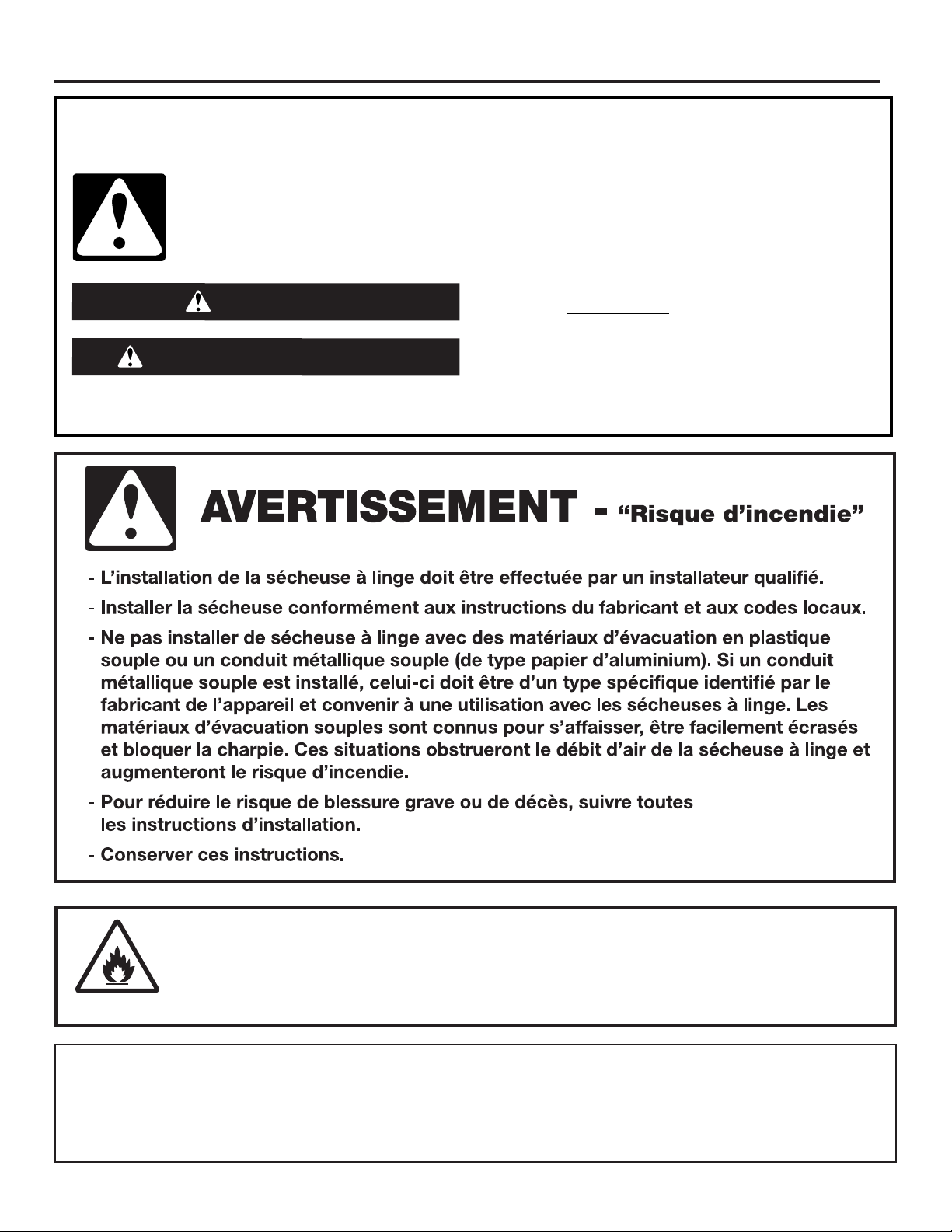
AVERTISSEMENT –
Risque d'incendie/
matières inammables
Ceci est un symbole supplémentaire d'alerte de sécurité vous signalant un risque d'incendie.
POUR VOTRE SÉCURITÉ
1. NE PAS UTILISER NI ENTREPOSER D’ESSENCE OU D’AUTRES MATÉRIAUX INFLAMMABLES À L’INTÉRIEUR OU ÀROXIMITÉ
DE CET APPAREIL.
2. NE PAS VAPORISER D’AÉROSOLS À PROXIMITÉ DE CET APPAREIL DURANT SON FONCTIONNEMENT.
3. NE PAS MODIFIER CET APPAREIL.
26
SÉCURITÉ DE LA SÉCHEUSE
IMPORTANTES INSTRUCTIONS DE SÉCURITÉ
AVERTISSEMENT: An de réduire le risque d’incendie, de décharge électrique ou de
blessures lors de l’utilisation de la sécheuse, il convient d’observer certaines précautions
fondamentales, notamment:
■ Lire toutes les instructions avant d’utiliser
la sécheuse.
■ Cette sécheuse est conçue uniquement
pour le séchage de vêtements et de
textiles ayant été nettoyés à l’eau. Ne pas
l’utiliser à toute autre fin.
■ Des articles ayant été au contact d’huile
peuvent s’enflammer spontanément,
surtout s’ils sont exposés à des sources
de chaleur, comme celle que produit
une sécheuse. Les articles chauffent,
entraînant une réaction d’oxydation de
l’huile. Le phénomène d’oxydation crée
de la chaleur. Si la chaleur ne peut pas
s’échapper, les articles peuvent devenir
suffisamment chauds pour prendre feu. Le
fait d’empiler d’entasser ou d’entreposer
des articles ayant été au contact d’huile
peut empêcher la chaleur de s’échapper et
créer un risque d’incendie.
■ Si l’on ne peut éviter que les tissus
contenant de l’huile végétale ou de
l’huile de cuisson ou des tissus ayant
été contaminés par des produits de
soins capillaires ne soient placés dans
la sécheuse, on doit d’abord les laver
dans de l’eau chaude et du détergent
supplémentaire – ceci réduira (sans pour
autant éliminer) le risque d’incendie.
■ Ne pas sécher d’articles qui ont été
précédemment nettoyés, lavés, trempés
ou tachés avec du pétrole, des solvants
pour nettoyage à sec ou d’autres
substances inflammables ou explosives;
ces substances dégagent des vapeurs qui
pourraient s’enflammer ou exploser.
■ Les articles comportant des taches de
substances telles que l’acétone, l’alcool,
le pétrole, le kérosène, les produits
détachants, la térébenthine, la cire ou
les décapants pour cire doivent être
lavés à l’eau chaude avec du détergent
supplémentaire avant d’être séchés dans
la sécheuse.
■ Ne pas faire sécher d’articles non lavés
dans cette sécheuse.
■ Ne pas utiliser cette sécheuse si on a
utilisé des produits chimiques industriels
pour le nettoyage. La présence éventuelle
de quantités résiduelles de produits
chimiques corrosifs ou décomposés dans
la charge peut endommager la sécheuse
et produire des fumées toxiques.
■ Ne pas laisser des enfants jouer sur
lesécheuse ou à l’intérieur de celle-ci.
Unesurveillance attentive des enfants est
nécessaire lorsque la sécheuse est utilisée
à proximité des enfants. Le nettoyage et
l’entretien ne doivent pas être effectués
par des enfants laissés sans surveillance.
Lesenfants de moins de 3ans devraient
être tenus à l’écart s’ils ne peuvent pas
être surveillés en permanence.
■ Ne pas utiliser la sécheuse si elle ne
chauffe pas, si elle semble défectueuse
ouendommagée. Contacter le propriétaire.
■ Ne pas installer ou entreposer la sécheuse
dans un endroit où elle serait exposée aux
intempéries.
■ Ne pas effectuer d’intervention non
autorisée sur les commandes.
■ Nettoyer le filtre à charpie de la sécheuse
avant ou après chaque charge.
■ Ne pas utiliser cette sécheuse si le filtre
àcharpie n’est pas installé.
■ Ne pas réparer ou remplacer une
quelconque pièce de la sécheuse ou
effectuer tout entretien qui ne serait
pas expressément recommandé dans
le Guided’utilisation et d’entretien ou
dans des instructions de réparation par
l’utilisateur que vous comprenez et que
vous êtes capables d’exécuter.
■ Les assouplissants pour tissu ou produits
similaires doivent être utilisés selon les
instructions de l’assouplissant pour tissu.
■ Les articles tels que le caoutchouc mousse
(mousse de latex), les bonnets de douche,
les textiles imperméabilisés, les articles
avec endos de caoutchouc et les vêtements
ou oreillers rembourrés avec matelassage
en mousse ne doivent pas être séchés
dansle tambour de la sécheuse.
■ La partie finale du programme de
séchage par culbutage a lieu sans
chaleur (programme de refroidissement)
pour que les articles soient laissés à une
température qui ne risque pas de les
endommager.
■ AVERTISSEMENT: Ne jamais arrêter une
sécheuse en phase de culbutage avant la
fin du programme de séchage, àmoins
de retirer et d’étendre rapidement tous
les articles afin que la chaleur se dissipe.
(Éviteles risques de combustionspontanée.)
27

SÉCURITÉ DE LA SÉCHEUSE
■ AVERTISSEMENT: Cet appareil ne
doit pas être alimenté par un dispositif
de commutation externe, comme une
minuterie, ni raccordé à un circuit
régulièrement ouvert et fermé par
l’opérateur du réseau.
■ En cas de coupure de l’alimentation
électrique, retirer rapidement la charge
et l’étaler pour éviter les risques de
combustion spontanée.
■ La zone située autour de l’ouverture
d’évacuation et les zones adjacentes
doivent être propres, exemptes de
peluches et poussières.
■ Les passages d’air à la base de l’appareil
ne devraient pas être obstrués par un
tapisou un objet semblable.
■ Cet appareil, bien que ce ne soit pas
obligatoire, est conçu pour être utilisé
dansun établissement public.
■ Cette sécheuse ne convient pas à une
utilisation par des personnes (y compris
des enfants de 8 ans et plus) à capacités
physiques, sensorielles ou mentales
réduites, ou possédant un manque
d’expérience et de connaissances,
àmoins qu’elles ne soient placées
soussupervision ou qu’elles aient reçu
desinstructions concernant l’utilisation
dela sécheuse par une personne
responsable de leur sécurité.
■ Retirer la porte du compartiment de la
sécheuse avant de retirer la sécheuse
pourun entretien ou de le mettre au rebut.
■ Ne pas accéder à l’intérieur de la sécheuse
pendant le fonctionnement du tambour.
■ Ouvrir la porte de la sécheuse arrête la
sécheuse.
■ Lors du chargement ou du rechargement
de la sécheuse, éviter de toucher
les parties métalliques chaudes du
tambour(risque de brûlure).
■ Retirer tous les objets des poches comme
les briquets et les allumettes.
■ Si la rotation du tambour est entravée
par des tissus coincés, déconnecter la
sécheuse de l’alimentation électrique
avant de retirer la source d’obstruction
avec précaution.
■ Si ce n’est pas possible en raison de
la construction ou de l’installation de
l’appareil, une déconnexion avec un
système de verrouillage en position
isoléesera fournie.
■ Seules les pièces de remplacement
autorisées devraient être utilisées en
casde défaillance.
CONSERVER CES INSTRUCTIONS
■ Cet appareil est muni d’une connexion de
mise à la terre à des fins fonctionnelles
seulement.
■ Ne pas installer cette sécheuse derrière
une porte pouvant être fermée à clé,
une porte coulissante ou une porte avec
charnière située du côté opposé à celui
de la sécheuse de telle manière que la
porte de la sécheuse ne puisse s’ouvrir
complètement.
■ L’air évacué ne doit pas être déchargé
dans un conduit servant à l’évacuation
defumée provenant d’appareils ménagers
à gaz ou autres combustibles.
■ Les ouvertures de ventilation pour
l’arrivée d’air frais dans la pièce et dans
lasécheuse ne doivent pas être obstruées
ou scellées.
■ Commande d’arrêt d’urgence:
Aprèsl’installation, un accès permanent
à la prise secteur ou à un interrupteur
bipolaire coupant l’alimentation secteur
doit être prévu pour permettre l’arrêt
immédiat de la sécheuse en cas d’urgence.
■ L’intérieur de la sécheuse et son
conduit d’évacuation doivent être
nettoyés régulièrement par un personnel
d’entretienqualifié.
■ Voir la section «Spécifications électriques»
dans «Exigences d’installation» pour les
instructions de mise à la terre.
■ Une aération adéquate est nécessaire
pouréviter le retour dans la pièce du gaz
en provenance d’appareils ménagers
utilisant des carburants comme
combustible, ycompris les feux ouverts.
■ La sécheuse doit être débranchée de sa
source de courant électrique durant les
interventions de service et le remplacement
des pièces.
■ Voir la section DIMENSIONS/DISTANCES
DE DÉGAGEMENT pour connaître les
distances de dégagement minimums
pourl’installation.
■ Capacité de charge IEC: 9,0kg
■ Cette sécheuse n’est pas munie d’un
cordon d’alimentation et d’une fiche.
Un moyen pour débrancher la source
d’alimentation incluant une séparation
des contacts de tous les pôles et qui
fournit une coupure d’alimentation lors des
conditions de surtension de catégorieIII
doit être fourni, sinon, lemoyen pour
débrancher la source doit être intégré
au câblage fixe en respectant les
réglementations de câblage.
28
MISE AU REBUT DE LA SÉCHEUSE
Le marquage de l’appareil est conforme à la directive européenne 2012/19/EU sur les équipements électroniques
et électriques, pour gestion des déchets.
En veillant à l’élimination correcte de ce produit, vous éviterez d’éventuelles conséquences néfastes pour l’environnement
et la santé humaine qui peuvent être associées au traitement inapproprié de ce produit lorsqu’il a été mis au rebut.
Le symbole fugurant sur le produit ou dans les documents qui accompagnent le produit indique que cet appareil ne doit pas
être traité comme déchet ménager; on doit plutôt le remettre à un centre de collecte spécialisé pour le recyclage des
équipements électriques et électroniques.
L’élimination de ce produit après mise au rebut doit être effectuée conformément aux prescriptions de la réglementation
locale de protection de l’environnement.
Pour l’information détaillée concernant le traitement, le recyclage et la récupération de ce produit, contacter la municipalité
locale, le service d’élimination des déchets ménagers, ou le commerçant qui a vendu le produit.
NOMENCLATURE DES MODÈLES:
MDE – Sécheuse Maytag – Électrique PN – Commande électronique – Sans paiement
## (p. ex., 28) – Numéro de type de modèle PD – Commande électronique– Chute de pièces activée
PR – Commande électronique – compatible carte de débit
29
OUTILS ET PIÈCES
Outils requis:
Tournevis à tête plate Tournevis à tête cruciforme
Clé à douille de 5/16 po
Niveau Couteau tout usage Tourne-écrou de 1/4po Pince multiprise
Brides de conduit Cale de bois de 27po
nouveau conduit d’évacuation)
Clé à tuyau de
8po ou10po
Tournevis ou embout
de sécurité Torx T20
Pistolet à calfeutrage et
composé de calfeutrage
(pourl’installation d’un
†
Clé à molette de
8po ou 10po dont la
mâchoire s’ouvre de (1po)
Clé à douille de 1po Pince (ouverture jusqu’à
19/16po)
Composé d’étanchéité
destuyauteries résistant
au type de gaz utilisé
Lampe de poche (facultative) Règle ou ruban à mesurer Couteau à mastic
Clés ouvertes de
1po
Pièces fournies:
■ Capuchons bottines (4)
■ Pieds de nivellement (4)
■ Modèles PN/PR: boîtier du lecteur de carte, matériel
REMARQUE: Le schéma du circuit électrique de cette sécheuse est situé à l’intérieur du panneau latéral, dans les ches techniques.
Caractéristiques techniques:
220–240 V ~50 HZ. 4575 W
Poids total: 69kg maximum
SPÉCIFICATIONSSPÉCIFICATIONS
Ces appareils sont vendus dans diverses régions aux critères de capacité de
mesure différents. Vous trouverez ci-dessous quelques-unes des formes de
mesures valables indiquées sur ce produit:
Capacité vêtements secs: Mesure de poids correspondant à un seuil minimal de
volume de linge sec, nécessaire à des ns de calcul des droits de douane.
Capacité IEC: Mesure de capacité représentant la capacité maximale de vêtements secs
et de textiles pour lesquels le fabricant conseille un programme spécique de traitement.
Capacité linge sec
10,5kg (23lb)
Capacité IEC
9,0kg (20lb)
Niveau sonore
LpA: 58 dB(A) {kPa+/-10 dB(A)}
†TORX et T20 sont des marques déposées de Acument Intellectual Properties, LLC.
30
 Loading...