

Page 1
Dishwasher — Technical Information
ADB3500AW*, MDBM755AW*, MDB7751AW*, MDB8751AW*,
MDB8951AW*
• Due to possibility of personal injury or property damage, always contact an authorized technician for servicing or
repair of this unit.
• Refer to Service Manual 16021814 for detailed installation, operating, testing, troubleshooting, and disassembly
instructions
All safety information must be followed as provided in Service Manual 16021814.
CAUTION
!
!
To avoid risk of electrical shock, personal injury, or death, disconnect power to dishwasher before servicing.
Benefits ADB3500AW* MDBM755AW*
MDB7751AW*
Wash cycles 5 4 6 5
Heavy Wash X X X X
Normal Wash X X X X
Quick Wash X
Light Wash X X X
Insta Wash X X
Auto Clean X X
Rinse Only X X X X
Features
Sound package
High Temp
Wash
Electronic
Controls
Sanitizer X X X
Sensor clean X X X X
Water Filtration
Delay Start
Energy Star X X X X
Hard Food
Disposer
Child lockout X X X X
Touch Pad
Controls
Silverware
Location
Low rinse aid
indicator
Sofsound III™
X X X X
X X X X
100% Filtered wash
water
2,4 or 6 Hour Delay
Start
X X X X
10 7 12 13
In door
X
QuietSeries™
Micro-Fine Plus
2,4 or 6 Hour
Delay Start
Compartment
WARNING
200
Filtration
Wash
MDB8751AW* MDB8951AW*
QuietSeries™
300
Micro-Fine Plus
Filtration
1-9 Hour Delay
Start
Wash
Compartment
QuietSeries™
400
Micro-Fine Plus
Filtration
1-9 Hour Delay
Start
Wash
Compartment
July 2005 1 16026394
©2005 Maytag Services
Page 2
Component Specifications
!
WARNING
To avoid risk of electrical shock, personal injury, or death, disconnect power to dishwasher before servicing.
Specifications Value
Power Source
Voltage AC 120 VAC
Amperage (Single Unit) 15 A
Frequency 60 Hz
Motor horsepower
1/3
Height−overall
Weight
Dimensions
33 ½” to 35 ¼”
71
Illustration Component Test Procedure Results
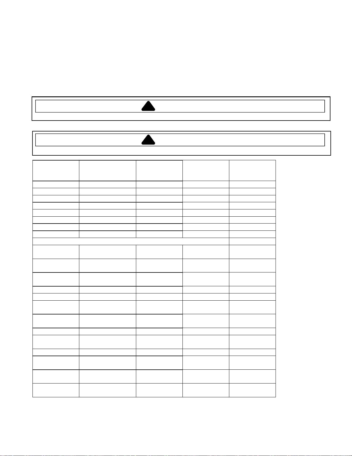
Dishwasher Motor
CCW rotation only
viewed from shaft
end.
1/3HP
120V/60hz, 3.2 amps,
3250 RPM
Main Wattage, 285
watts
Start Wattage, 1115
watts
Control Panel See Component Specifications/
Measure resistance from
ST5 (Motor Common – blue) to ST8
(Motor Main - yellow) .........................
See Component Specifications/Motor
Connections for details.
Membrane Readings for
troubleshooting/pin-out instructions.
3 to 4 Ω
Water valve
120V/60hz, 7 watts
1.13 ± .10 gpm at 20120 psi
Vent wax motor
120V with 1/4"
actuation stroke
within 90 seconds
Measure resistance from
J6 Pin 4 Aqua (Float switch) to ST4
Black (Common) ...............................
Measure resistance from J6 Pin 1
Purple (Vent) to ST4 Black (Common)
...........................................................
1.1 k Ω
(This value assumes the float switch is
closed).
1.2 k Ω
16026394 2 July 2005
©2005 Maytag Services
Page 3
Component Specifications
!
WARNING
To avoid risk of electrical shock, personal injury, or death, disconnect power to dishwasher before servicing.
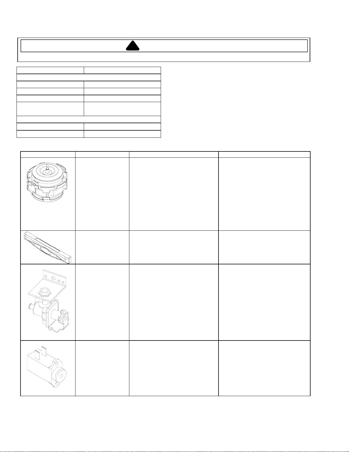
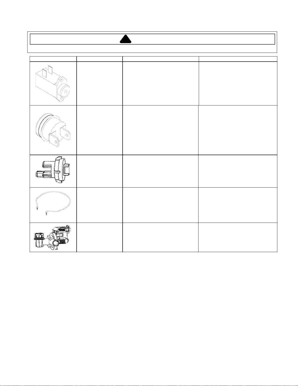
Illustration Component Test Procedure Results
Dispenser wax motor
120V with 1/4"
actuation stroke
within 90 seconds
Limit Thermostat
Measure resistance from J6 Pin 3
Tan (Dispenser) to ST4 Black
(Common) .........................................
Close on Temperature drop @ 149°F
± 7°F (Temp) .......................................
Open on Temperature drop @ 164°F
± 4°F (Temp) .......................................
2 k Ω
0 Ω = Closed
Infinite Ω = Open
Sensor/Thermistor
10KΩ ± 3% at 77°F and 2.4 k Ω ±
6.5% at 140°F
J5 pin 1 - Orange (Temp) to J5 Pin 4 -
Red (Neutral) .......................................
Heater/Heating
Element
120v/60hz, 650 watts
± 5% in air, 830 watts
± 5% in 90°F water
Drain Motor
120v/60hz
45 watts
Measure resistance from ST1
Red/Black (Heater) to ST11 White
(Common) ...........................................
Measure resistance from
ST6 Gray (Drain) to ST4 Black
(Common) ...........................................
Infinite Ω = Open
0 Ω = Closed
16 Ω
(This value assumes the high limit
thermostat is closed).
25 Ω
July 2005 3 16026394
©2005 Maytag Services
Page 4

Component Readings/Testing
!
WARNING
To avoid risk of electrical shock, personal injury, or death, disconnect power to dishwasher before servicing.
A Manual Func ti on Test may be st arted by pressing the key
5 times fol l ow ed by the key within8 seconds.
The LED will 3 times indicating manual test mode is
Normal W ash Flash
active. Specific ke y pads will turn on or off a component a s fo ll o w s:
Hi Temp Wash Wash Mot or Hi Temp Wash
Heated Dry Heating Element Heated Dry
Cycles Select / Normal
First Press No Action Heavy Wash
Second Press Dispenser Normal Wash
Third Press Drain Pump Light Wash / China Cryst al
The test will cancel 120 seconds after the last keypad is pr essed. The display
(if available) will show ‘99’ until the remaining timeout period is less than 99
seconds. At this point it will countdown until the mode times out, is cancelled,
or another key is pressed. To cancel test, press the keypad.
To check control LED’s and components, enter . If control
fails to perform sequence as described, and a fault is detected, determine
failure as described in the . If a load component failure has
been diagnosed, proceed to the . To check individual
load com p o ne nts for proper operation, enter . Follow
test procedure as described. Repair or replace component as neede d.
: The or may be detected during
Note High Current Low Current Motor Error
a wash cyc l e selected by a consu mer. If this happe ns, the control will go i n t o a
30 second auto restart mode and shut down if the unit is not able to restart the
motor.
Manual Func tion Test
Start
KEY Function LED
Delay Water Inlet Valve Delay
, Field Servic e Test
Diagnostic Tips
Field Service Test
Manual Function Te st
Manual Function Test
Heated Dry
Start / Cancel
Membrane Readings
(All Models)
Heavy Wash
Normal Wash
Light Wash / China Crystal / Gentle Wash
Quick
Rinse Only
Auto Clean / Sensor Clea n
Heated Dry
Sanitize
Hi Te mp Wash
*
*
*
*
*
*
/
Connector
J1
J1
J1
J1
J1
J1
J1
J1
Measu r e Between
Pin 9 - Pin 5
Pin 9 - Pin 6
Pin 9 - Pin 7
Pin 9 - Pin 8
Pin 10 - Pin 5
Pin 11 - Pin 5
Pin 11 - Pin 6
Pin 11 - Pin 8
(Front Only Controls)
Cycle Select
Start / Cancel
Delay
T ough Scrub Plus / Su per Scrub / Power Sc ru b
T ough Scrub / Extra Wash / Hi Temp
Insta Wash
Model ID Jumper
An unpressed switch will read as an open circuit.
A pressed switch wi l l read as 10 k .
* On select mo dels
*
*
*
*
Connector
J1
J1
J1
*
J1
J1
J1
J1
Measu r e Between
Pin 9 - Pin 5
Pin 10 - Pin 6
Pin 10 - Pin 7
Pin 10 - Pin 8
Pin 11 - Pin 7
Pin 12 - Pin 5
Pin 12 - Pin 7
A Field Service Test may be started by pressing the key 6 times
followed by the key within 8 seconds. This test must be performed with
clean water to insure proper sensor performance.
“88” will appear in the di splay (if available*) and the follo wing sequence of
events will occur:
SECONDS
The time for the Thermistor chec k / Turbidy Sensor che ck & calibration may
vary slight ly.
The Field Service Test will not repeat. The LED will during
the test mo de. All I nd i cator lights (except ) will illum inate. If the
dishwasher door is opened during the test, the test sequence will pause, and
resume when the door is closed. To cancel test, press the
keypad.
The cont r ol has been designed to test the Sensor Memory and Motor. During
the F ield Servi ce Test, i f a fault has been detected, the test will abort any time
after the m ot or current has been checked and 2 or more LED ' s wil l begin to
Flash Memory / Software Check
start ed. The LED and one of t he following:
* On select models
Insta Wash
Tough Scrub Plus / Super Scrub / Power Scrub
160° Wash
Tough Scrub / Extr a Wash / Hi Temp
Model ID Jumper
Start / Ca nc el
Delay
Start
106
5
120
180
120
4
. A will occur immediately after the test is
(Delay / Delay 2 hr)
*
*
(Top Only Controls)
Insta Wash
Tough Scrub Plus / Super Scrub
160° Option
Tough Scrub / Extr a Wash / Hi Temp
Model ID Jumper
Start Cancel
Delay
*
Field Serv i c e Test
FUNCTIONS / ACTIVE LOADS
Vent Wax Motor / Water Valve
Thermistor check / Turbidity Sensor check &
calibration - no loads active.
Wash Motor / Vent Wax Motor / Dispenser
Wax Motor
Wash Motor / Heater / Vent Wax Motor
Drain Pump
Water Valve
Heavy Wash
Turbidity Sensor Hi Temp Wash
Thermistor Heavy Wash
Motor Normal Wash
- high current - LED
Motor Light Wash
- low current - LED
Memory Failure Heated Dry
- failure - LED
- failur e - LED
- LED
Heated Dry
Heavy Wash Flash
the
,,
Start / Cancel
Membrane Readings
(Front & Top Controls)
J1
J1
J1
J1
J1
J3
J3
J1
J1
J1
J1
J1
J1
J1
Measur e B et w e e n
Pin 10 - Pin 6
Pin 10 - Pin 7
Pin 10 - Pin 8
Pin 11 - Pin 7
Pin 12 - Pin 8
Pin 9 - Pin 5
Pin 9 - Pin 6
Measur e B et w e e n
Pin 10 - Pin 6
Pin 10 - Pin 7
Pin 10 - Pin 8
Pin 11 - Pin 7
Pin 12 - Pin 6
Pin 13 - Pin 12
Pin 13 - Pin 14
Connector
*
*
*
*
Connector
*
*
Load Readings
Heater¹
Wash Motor
Drain Motor
Dispenser Wax Motor
Water Valve²
Thermistor
Notes:
1. This value as su mes the high limit th er m ostat is closed.
2. This value as sumes the float swi tch is cl osed.
3. Results are approximated values.
ST5 (Motor Common ) - ST8 (Motor Main)
16026394 4 July 2005
©2005 Maytag Services
Measure Betw een
ST1 (Heater) - ST11 (Dlb Neutral)
ST6 (Drain) - ST4 (Dlb Line)
J6 Pin 3 (Di sp ) - ST4 (Dlb Lin e)
J6 Pin 4 (Inlt) - ST4 (Dl b Li ne)
J5 Pin 1 (Temp) - J5 Pin 4 (Neutral)
Result
16
3 to 4
25
2k
1.1k
See Comp on ent Info
Page 5

Electrical Diagnostics
!
WARNING
To avoid risk of electrical shock, personal injury, or death, disconnect power to dishwasher before servicing.
*** A resistor in the control board wired in parallel will result in an approximate reading of 4.0 k ohms
with connector J5 plugged in.
** Nominalvalueforohmsof electrical resistance of component only. Thesevalueswillvary slightly
due to the additional resistance of the wire harness. Greater variation can occur if the component is
still warm from being energized during testing.
3
Perform the resistance checks on the component(s) in question at the locations shown on the chart.
* Select ModelsOnly.
2
(A white plastic latch must be inserted in the latch assembly for this test.)
> With one ohm meter lead connected to the white (neutral) power lead, you should have continuity at
stakelugs10&11.
> With one ohm meter lead connected to the black (line) power lead, you should have continuity at
stakelugs3&4,andpin#8onconnectorJ5.
To check continuity from ends of power leads to control board through door switches
1
Use the "Manual Function Test" as described on the electrical schematic sheet to
check components before
Pin#12345678 Pin#1234 StakeLug11109876 54321
OR RD RD AQ PU BK PU TN AQ
opening the door to perform continuity testing or replacing parts.
J5 J6
connector unplugged)***
2.4K* +/- 6.5% @ 140
10K* +/- 3% @77
o
F
o
F
*Vent WM
(1.2K**)
Resistance Check Points and Values
Thermistor (thru harness only with
Disp. WM
(2K**)
Circuit Board
mustbe closed)
WH WH
before performing any resistance or
Always
YL GY BU BK B K RD
continuity checks.
remove power to the unit
(High limitt'stat must
(14.5 - 16.5**)
be closed)
Heater
Wash Motor
(3 - 4**)
(25**)
Water V alve
(float switch
(1.1K**)
Drain Motor
BK
July 2005 5 16026394
©2005 Maytag Services
Page 6

Control Definition
!
To avoid risk of electrical shock, personal injury, or death, disconnect power to dishwasher before servicing.
Designed to provide a
longer cycle for
washing items with
heavy food soils.
water usage is 8
gallons.
Designed to wash
loads containing
dishes with normal
amounts of food
soils. Water usage
ranges from 3 to
6 gallons.
Designed for light
food soils. The
cycle ends with
a rinse and does
not include drying.
water usage is 4
gallons.
Rinses dishes being
held until the dishwasher
is full, and another cycle
is selected. This cycle
helps reduce the
potential for developing
odors. Water usage
is 2 gallons.
Light Wash- Designed to wash loads containing dishes that are lightly soiled Water usage is 5 gallons.
Insta Wash- Designed to wash loads containing dishes that are lightly soiled Water usage is 5 gallons.
Auto Clean- Designed to auto select the number of fills and length of wash times based on soil level of dish load.
Water usage ranges from 3 to 8 gallons.
Tough Scrub- This option adds fills, heat and/or wash time to the wash cycle.
16026394 6 July 2005
©2005 Maytag Services
Designed to auto
select the number
of fills and length
of wash times
based on soil
level of dish
load. Water
usage ranges
from 3 to 8
gallons.
WARNING
Delays the start of
the dishwasher
based on user
selection.
This option improves drying
results by turning the heating
element on and off during the
dry portion of the cycle.
This option monitors
cycles for sanitization.
This option raises
Temperature in the
Final rinse to 160
° F
Page 7

Control Definition/Motor Connectivity
!
To avoid risk of electrical shock, personal injury, or death, disconnect power to dishwasher before servicing.
120V/60hz, 3.2 amps, 3250 RPM
July 2005 7 16026394
©2005 Maytag Services
WARNING
Green
Yellow
Blue
(Common)
1/3HP
(Start)
(Ground)
(Main)
Wire harness
Connection plug
Page 8

Cycle Chart
A
/
!
To avoid risk of electrical shock, personal injury, or death, disconnect power to dishwasher before servicing.
1. All times are approximate.
2. Temperature checks force a maximum 20 minute heating delay to reach the desired temperature.
3. The cycle definition gives the minimum and maximum possible cycle lengths. Actual cycle length and executed cycle functions will vary based on the sensor input.
4. Fill length varies between different models.
Auto Clean/Sensor Clean
Sanitize Sanitize Light Wash
160° Option 160° Option
Temperature Options (Available on select models)
adds 5 minutes unheated circulation prior to rinse aid dispen se.
Notes
: If the option is available for a given cycle, it for ces a 140°F temp check at the end of the main wash for the , a 154 °F temp check prior to the rinse aid dispense in the final rinse, and
SENSOR CLEAN CYCLE
AUTO CLEAN CYCLE/
(128 Minutes - max)
(94 Minutes - min)
: If the is available for a given cycle, it forces a 160°F temp check prior to the rinseaid dispense in the final rinse.
1:46 max
1:36 min
FILL
WASH
PRE
8:00
DRAIN
2:20
Available Options:
Hi Temp Wash
Tough Scrub/
Tough Scrub Plus Tough Scrub
Extra Wash/Hi Temp
- This option has no effect on this cycle.
/Super Scrub/Power Scrub
- This option adds an additional 5 minutes of heated wash to the wash
1:46 max
- This option is the same as but the main wash temp check is boosted to 145°F.
HEATED
8:00
(133 Minutes - max)
WASH
2:20
(132 Minutes - min)
1:36 min
HEAVY WASH CYCLE
PRE
DRAIN
Tough Scrub Plus/Super Scrub/Power Scrub Tough Scrub
FILL
- This option is the same as but the main wash temp check is boosted to 145°F.
HEATED
SKIP?
1:46 max
1:36 min
FILL
DISP
DET
HEATED
WASH
25:00
CHECK
TEMP
140°F
DRAIN
2:00
1:46 max
1:36 min
FILL
HEATED
RINSE
10:00
PRE
1:46 max
1:36 min
FILL
HEATED
WASH
8:00
main and a 10 minute heated pre- r inse.
DISP
DET
HEATED
WASH
22:00
CHECK
TEMP
140°F
DRAIN
2:00
1:46 max
1:36 min
FILL
WARNING
Available Options:
Hi Temp Wash
Tough Scrub/Extra Wash/Hi Temp 5
- This optio n ov e r rides the sensor’s decision to sk i p cycle functions / modify temp checks and adds an additional minutes of heate d wash to the ma in wash.
NORMAL WASH CYCLE
(117 Minutes - max)
(97 Minutes - min)
- Overrides the sensor’s decision to modify the temp checks and skip a rinse.
1:46 max
1:36 min
FILL
HEATED
WASH
PRE
8:00
DRAIN
2:20
SKIP?
1:46 max
1:36 min
FILL
DISP
DET
HEATED
WASH
26:00
HEATED
WASH
SKIP?
2:00
SEE NOTE
CHECK
TEMP
TC 1
DRAIN
2:00
1:46 max
1:36 min
FILL
Available Options:
Hi Temp Wash
Tough Scrub/Extra Wash/Hi Temp
Tough Scrub Plus/Super Scrub/Power Scrub Tough Scrub
- This option is the same as but the main wash temp check is boosted to 145°F.
GENTLE WASH/QUICK WASH
CHINA/CRYSTAL CYCLE/
82 Minutes - Max
81 Minutes - Min
- This option boosts the final rinse temp check to 145°F.
- This optio n ad ds an 8 minute pre-wash and 5 minutes of heat ed wash to the main wash.
1:46 max
1:36 min
FILL
DISP
DET
HEATED
WASH
10:00
DRAIN
2:00
1:46 max
1:36 min
FILL
HEATED
RINSE
10:00
DRAIN
2:00
1:46 max
1:36 min
FILL
HEATED
RINSE
15:00
CHECK
TEMP
140°F
Available O p tions:
Only the option is available with the cycle.
LIGHT WASH CYCLE/
INSTA WASH CYCLE
Heated Dry Insta Wash
51 Minutes - Max
20
Minutes - Min
1:46 max
1:36 min
FILL
DISP
DET
HEATED
WASH
4:00
DRAIN
2:00
1:46 max
1:36 min
FILL
HEATED
RINSE
2:00
DRAIN
2:00
1:46 max
1:36 min
FILL
HEATED
RINSE
3:00
DRAIN
2:00
Available Options:
No options are available with the cycle.
RINSE ONLY CYCLE
9 Minutes
Rinse Only
1:46 max
1:36 min
FILL
RINSE
5:00
DRAIN
2:00
FILL
0:02
HEATER
3:00
DRY CYCLE
ON
HEATER
OFF
1:30
(Front Only Display Models)
SKIP?
DRAIN
2:00
1:46 max
1:36 min
HEATED
RINSE
10:00
PRE
FILL
DRAIN
2:00
RINSE
SKIP?
10:00
PRE
DRAIN
2:00
RINSE
DISP
AID
RINSE
5:00
FILL
0:02
(FrontTop
HEATER
1:00
ON
HEATER
OFF
1:30
HEATED
RINSE
10:00
PRE
DRAIN
2:00
1:46 max
1:36 min
FILL
HEATED
RINSE
20:00
CHECK
TEMP
145°F
RINSE
DISP
AID
RINSE
5:00
This represents the portion of a cycle that be
omitted. The determination of whether a segment
is skipped or not is made by input from the sensor.
SKIP?
DRAIN
2:00
FILL
0:02
CYCLE
30:00
DRY
1:46 ma x
1:36 min
FILL
HEATED
RINSE
10:00
PRE
DRAIN
2:00
1:46 max
1:36 min
FILL
HEATED
RINSE
20:00
CHECK
TEMP
145°F
RINSE
DISP
AID
RINSE
5:00
DRAIN
2:00
FILL
0:02
CYCLE
30:00
DRY
1:46 ma x
1:36 min
FILL
HEATED
RINSE
20:00
TC 1: If sensor detects lighter soil, the temp check will be 128 ° F
TC 2: If sensor detects lighter soil, the temp check will be 140 ° F
If sensor detects heavier so il, the temp check will be 140 ° F
If sensor detects heavier soil, the temp check will be 145 ° F
SEENOTE
CHECK
TEMP
TC 2
RINSE
DISP
AID
RINSE
5:00
DRAIN
2:00
FILL
0:02
CYCLE
30:00
DRY
DRAIN
2:00
FILL
0:02
CYCLE
30:00
Notes: If is not selected, the heater will not be activated during the dry cycle.
3:00or1:00
ON
If is selected, the first two minutes of heating is changed to 2 minutes of unheated at the end of
t dry cycle.
he
Heated Dry
160° Option
HEATER
OFF
3:00
DRY
HEATER
1:00
ON
HEATER
OFF
3:00
HEATER
1:00
ON
HEATER
OFF
3:00
HEATER
1:00
ON
HEATER
OFF
3:00
HEATER
1:00
ON
HEATER
OFF
3:00
HEATER
1:00
ON
M
Y
OFF
7:00or9:00
Note: If is not selected, the heater will not be activated during the dry cycle.
HEATER
DRY CYCLE
TopOnly Display Models)
HEATER
HEATER
1:00
ON
Heated Dry
HEATER
OFF
1:30
HEATER
1:00
ON
HEATER
OFF
1:30
HEATER
1:00
ON
HEATER
OFF
1:30
HEATER
1:00
ON
HEATER
OFF
1:30
HEATER
1:00
ON
HEATER
OFF
1:30
HEATER
1:00
ON
HEATER
OFF
9:30
16026394 8 July 2005
©2005 Maytag Services
Page 9

Wiring Diagram
!
WARNING
To avoid risk of electrical shock, personal injury, or death, disconnect power to dishwasher before servicing.
GY
BK
LI
BK
BK
DOOR SWITCH
(LI)
BK
RD
BK
BK
BK
BU
GY
YL
WH
WH
AQ
TN
BK
BK
BK
BU YL
GY
WH
WH AQ
TN
RD
CIRCUIT BOARD
J6
PIN
1
WIRES NOT CONNECTED
WIRES CONNECTED
DOOR SWITCH
KEY
(N)
HEATER
BK
WASH MOTOR
NOT E : SO ME W IR ES HAVE
STRIPES. STRIPED WIRES ARE
LABELED WITH THE SOLID
COLOR FIRST AND THE STRIPE
COLOR SECOND.
RD
WH
RD
BK
OVERLOAD
MAIN
GROUND
START
(TUB SHIELD)
GR
WH
WH
N
GR
WH
WH
THERMOSTAT
BK
YLBU RD
GR
(TERMINAL
BOX)
GR
GR
WH
WH
YL
CAPACITOR
MOTOR
YL
RD
WH
WH
(HINGE)
GR
EXAMPLE: A RED WIRE WITH A
BLACK STRIPE WOULD BE
LABELED
RD
BK
WATER
VALVE
RD
MOTOR
DRAIN
BK
AQ
GY
BK
AQ
AQ
TN
SWITCH
FLOAT
DISPENSER
BK
BK
AQ AQUA
BK BLACK
BU BLUE
BR BROWN
GY GRAY
GN GREEN
OR ORANGE
PK PINK
PU PURPLE
RD RED
TN TAN
WH WHITE
YL YELLOW
COLOR CODE
TN
BK
BK
BK
OR
SENSOR & THERMISTOR
OR PU RDAQ
OR
BK
TN
BK
BK
PU
PU
AQ
BK
AQ
RD
RD
PU
OR
AQ
RD
OR
BK
PU
RDAQ
RD
OR
J5
PIN
1
BK
July 2005 9 16026394
©2005 Maytag Services
 Loading...