

Page 1
Instruction Sheet
Locking
Nut
Replace
if
required
Seal
Tool
Grommet
Replace if
required
Washer
Kit
“O”Ring
Lip
Seal
16021976
Instruction
Sheet
!
WARNING
5. 35-2968 Spanner (Used for leverage
to remove rear pulley).
6. Torque Wrench
7. T-20 Torx™ Driver
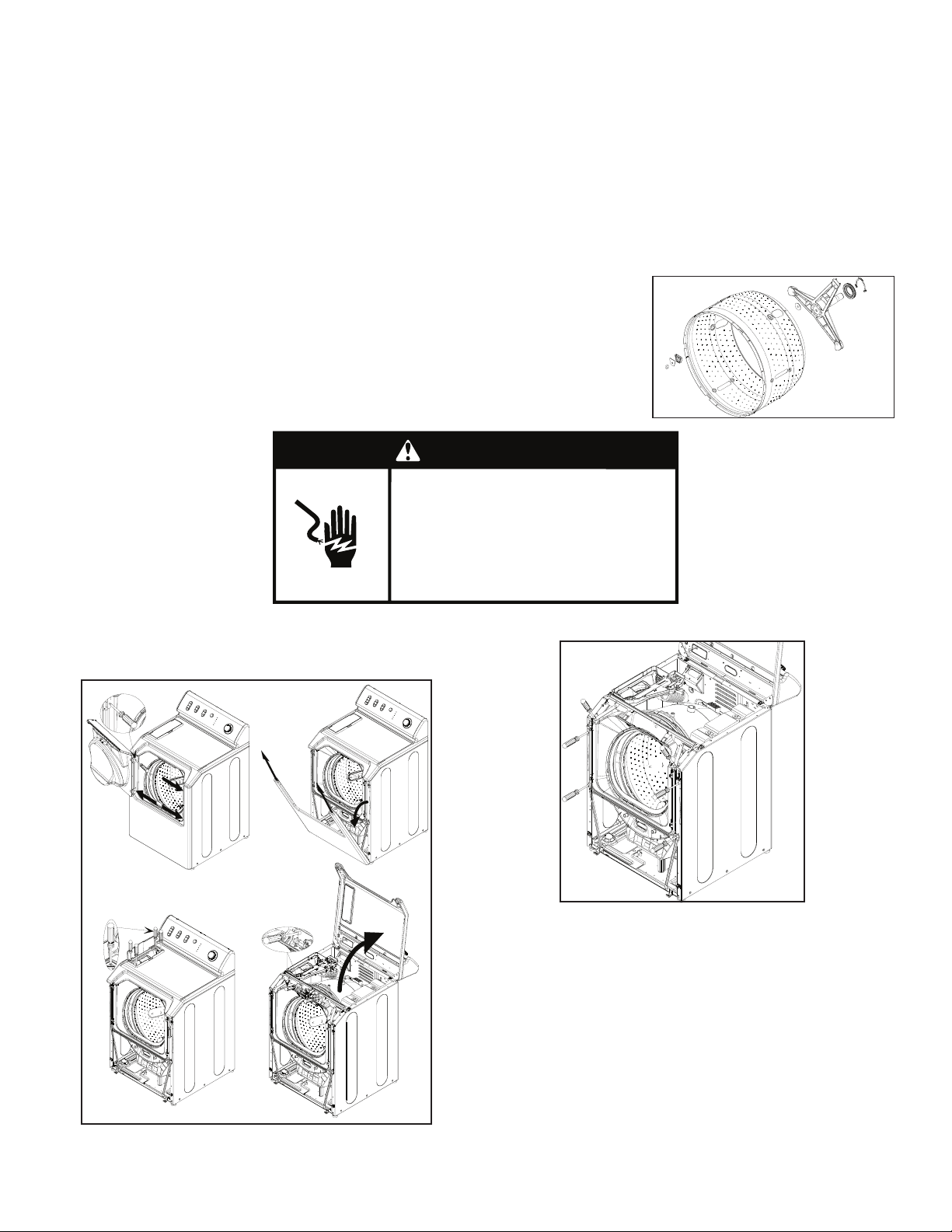
1. Disconnect power to the machine.
2. Remove the front panel, top cover, front shroud and shroud support brackets.
Spinner Support Assembly
Kit Includes:
Molykote Grease
Spinner Support Assy
Locking Nut - Replace if required
Seal Tool
Grommet - Replace if required
Washer Kit
“O” Ring
Lip Seal
Instruction Sheet
Explanation:
The spinner tub support attaches to the spin basket and the spinner support extends through a
seal system to the exterior of the outer tub, with a pulley attached to the end of the shaft. This
assembly supports the spin basket and transfers the rotation of the drive pulley directly to the
rotation of the spin basket.
NOTE: Whenever the spinner tub support is removed, replacement of the shaft seal system
should be performed.
Tools:
1. 5/16” Nut Driver
2. 9/16”, 1/2” Socket and Ratchet
3. Phillips Screw Diver
4. Flat Blade Screw Driver
5. 35-2968 Spanner (Used for leverage to remove rear pulley).
6. Torque Wrench
7. T-20 Torx™ Driver -
WARNING
†
1. Disconnect power to the machine.
2. Remove the front panel, top cover, front shroud and shroud
support brackets.
Electrical Shock
Hazard
Disconnect power before servicing.
Replace all parts and panels before
operating.
Failure to do so can result in death
or electrical shock.
3. Remove Shroud Support Brackets.
4. Remove the Outer Tub Cover.
a. If the washer has a heater installed into the tub cover,
remove the wires from the tub cover and the wire retainer
screws.
b. Usingaatbladedscrewdriver,slide the screwdriver
under the clip and pry to remove the clip. Remove the
remaining clips from the outer tub cover.
c. Gently remove the cover from the outer tub.
† - ®TORX and T20 are registered trademarks of Acument Intellectual Properties, LLC.
Instruction Sheet W11086225 Rev. A 1/17
— 1 —
(continued)
Page 2
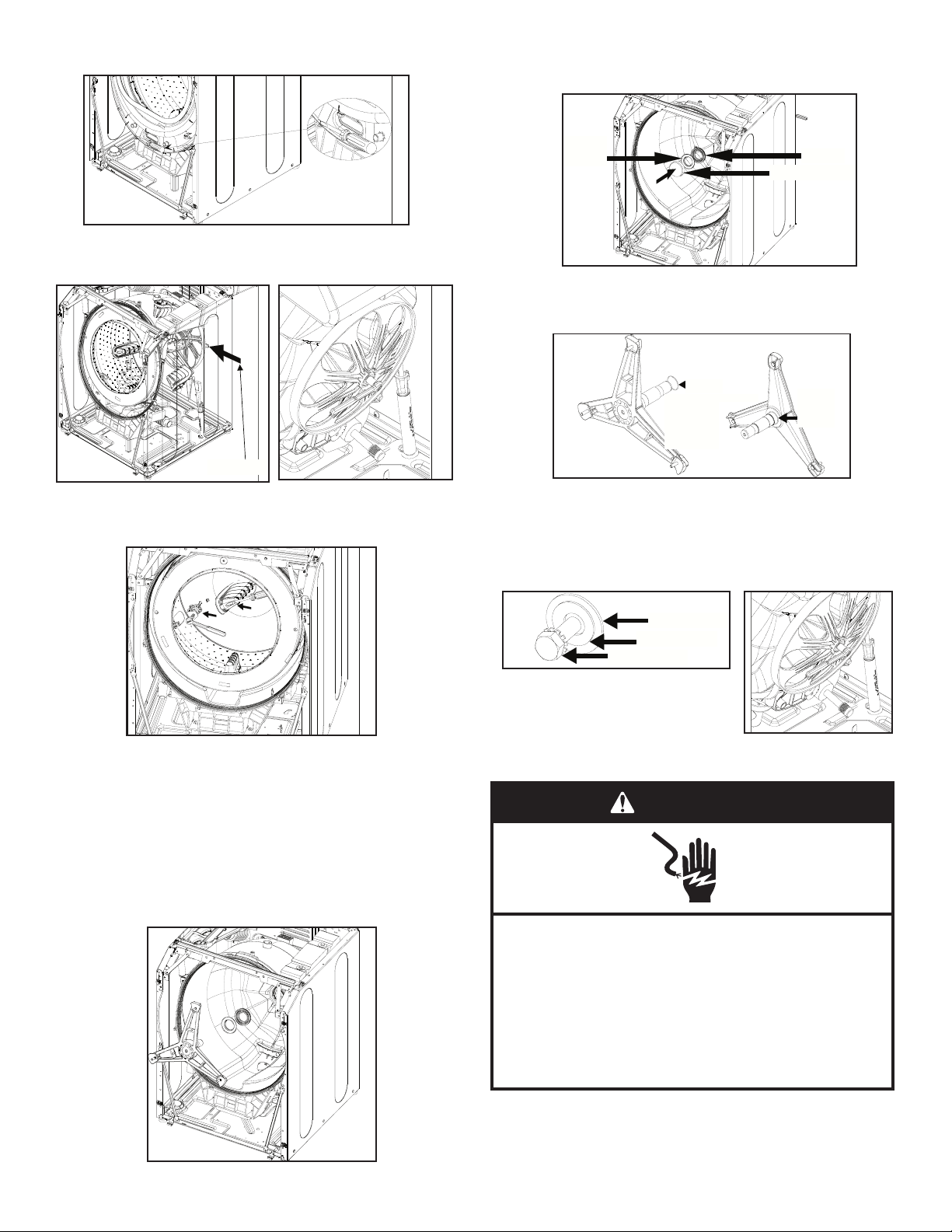
5. Remove Drive Pulley by standing over top of washer, while
wire retainer screws.
Remove the remaining clips from the outer tub cover.
Wrench
11. Slide “O”-Ring onto the new shaft and fully seat onto the base of the Spinner Support. Apply Molykote
grease on spinner shaft. Spread grease thin on shaft to avoid excess from getting into next wash load.
11. Slide “O”-Ring onto the new shaft and fully seat onto the base of the Spinner Support. Apply Molykote
grease on spinner shaft. Spread grease thin on shaft to avoid excess from getting into next wash load.
“O”-Ring
Apply Molykote Along Shaft
Fully seated
O-Ring
12. Reinstall the 3 plastic washers on Spinner. Assemble the Spinner and Spinner Support Shaft. Position
the Spinner with Spinner Support shaft into the Outer Tub.
13. Install the Drive Pulley onto the Spinner Support Shaft. Replace the tabbed pulley washer with new 1-
1/4” washer along with the new retaining bolt. Tighten retaining bolt to 33 ft. lbs. Torque drawing the
shaft and seals into proper alignment.
Fully seated
O-Ring
leaning the Outer Tub forward, then roll the Drive Belt of Pulley.
10. Place the new seal onto the insertion tool. Wipe the outside
diameter of the seal with a soap solution to help installation.
Linethesealupto the bearing housing and press rmlyinto
the housing until the seal is fully seated.
6. Remove the bolt (9/16” socket) in the center of the Drive Pulley.
Slide Pulley off of Spinner Support Shaft. If necessary use
Spanner Wrench to apply leverage to loosen Pulley.
Wrench
WRENCH
7. Separate the Spinner Support from the Spin Basket by removing
the3rearBafesinsidetheSpinTub.
8. Remove 3 lock nuts with a 1/2” socket.
STEEL
WASHER
LIP SEAL
INSERTION TOOL
11. Slide “O”-Ring onto the new shaft and fully seat onto the base
of the Spinner Support. Apply Molykote grease on spinner shaft.
Spread grease thin on shaft to avoid excess from getting into
next wash load.
“O”-Ring
O-RING
Apply Molykote Along Shaft
APPLY
MOLYKOTE
ALONG
SHAFT
FULLY
SEATED
Fully seated
O-RING
O-Ring
12. Reinstall the 3 plastic washers on Spinner. Assemble the Spinner
and Spinner Support Shaft. Position the Spinner with Spinner
Support shaft into the Outer Tub.
13. Install the Drive Pulley onto the Spinner Support Shaft. Replace
the tabbed pulley washer with new 1-1/4” washer along with the
new retaining bolt. Tighten retaining bolt to 33 ft. lbs. Torque
drawing the shaft and seals into proper alignment.
1-11/16” WASHER
1-11/16” Washer
1-1/4” Washer
1-1/4” WASHER
Retaining Bolt
RETAINER BOLT
9. Remove Spin Basket by lifting off of threaded studs on Spinner
Support.
A multi-lipped water seal is positioned on the Spinner Support
Shaft leading to the Outer Tub Bearings. This prevents water
from inside the tub from reaching the bearings. The water seal
is accessed only by removing the Spinner Support Shaft and
is comprised of a stainless steel seal face which mates with a
rubber gasket.
Remove the rubber seal gently from inside the Outer Tub.
Remove the plastic spacer, if so equipped. Once removed, clean
the surface exposed under the seal. Discard the rubber seal and
plastic spacer.
© Whirlpool Corporation 2017
(All Rights Reserved)
14. Run the Drive Belt over Motor Pulley and roll onto Drive Pulley.
15. Install Front Shroud Front Panel and Top Cover.
WARNING
Electrical Shock Hazard
Plug into a grounded 3 prong outlet.
Do not remove ground prong.
Do not use an adapter.
Do not use an extension cord.
Failure to follow these instructions can result in death,
fire, or electrical shock.
16. Plug in washer or reconnect power.
17. Testwasher for properoperation.Cyclewasherthrough a ll
and drain cycle to check for leaks.
— 2 — W11086225 A
Page 3

Risque de choc électrique
Déconnecter la source de courant
électrique avant l'entretien.
Le non-respect de ces instructions peut
causer un décès ou un choc électrique.
Replacer pièces et panneaux avant de
faire la remise en marche.
AVERTISSEMENT
Fiche d’instructions
Locking
Nut
Replace
if
required
Seal
Tool
Grommet
Replace if
required
Washer
Kit
“O”Ring
Lip
Seal
16021976
Instruction
Sheet
!
WARNING
5. 35-2968 Spanner (Used for leverage
to remove rear pulley).
6. Torque Wrench
7. T-20 Torx™ Driver
1. Disconnect power to the machine.
2. Remove the front panel, top cover, front shroud and shroud support brackets.
Ensemble de support d’essoreuse
La trousse inclut :
Graisse Molykote
Ensemble de support d’essoreuse
Écrou de blocage Remplacer au besoin
Outil à jointage
OEillet Remplacer au besoin
Trousse de rondelles
Joint torique
Joint à lèvre
Feuille d’instructions
Explications :
Lesupportdecuved’essoreusesexeaupanierd’essorageetlesupportd’essoreuses’étend
aumoyend’unsystèmed’étanchéitépoursortirdelacuveextérieure;etunepoulieestxéeà
l’extrémité de l’axe. Cet ensemble supporte le panier d’essorage et transmet le mouvement de
rotation de la poulie d’entraînement directement au panier d’essorage.
REMARQUE : Le système d’étanchéité de l’axe doit être remplacé chaque fois que le support
de cuve d’essoreuse est enlevé.
Tools:
1. Tourne-écrou de 5/16 po
2. Douille de 9/16, 1/2 po et clef à rochet
3. Tournevis Phillips
4. Tournevis à lame plate
5. Clef à écrou 35-2968 (Utilisée comme levier pour enlever la
poulie arrière).
6. Clef dynamométrique
7. Entraînement Torx™ T-20 -
†
1. Débranchez l’alimentation électrique de la machine.
2. Déposez le panneau avant, le couvercle supérieur, le
carénage avant et ses ferrures de supports.
†®TORX et T20 sont des marques déposées de Acument Intellectual Properties, LLC.
Fiche d’instructions W11086225 Rév. A 1/17
3. Déposez les ferrures de support du carénage.
4. Déposez le couvercle de la cuve extérieure.
a. Si une chaufferette est installée dans le couvercle de la
cuvedelaveuse,enlevezleslsprovenantducouvercle
delacuveetlesvisdexationquilesretiennent.
b. Faitesglisseruntournevisàlameplatesousl’attache
et levez-la pour la retirer. Enlevez les autres attaches
du couvercle de la cuve extérieure.
c. Déposez avec douceur le couvercle de la cuve
extérieure.
— 3 —
(suite)
Page 4

5. Déposez la poulie d’entraînement en vous tenant par-
wire retainer screws.
Remove the remaining clips from the outer tub cover.
Wrench
Insertion Tool
11. Slide “O”-Ring onto the new shaft and fully seat onto the base of the Spinner Support. Apply Molykote
grease on spinner shaft. Spread grease thin on shaft to avoid excess from getting into next wash load.
“O”-Ring
Apply Molykote Along Shaft
Fully seated
O-Ring
11. Slide “O”-Ring onto the new shaft and fully seat onto the base of the Spinner Support. Apply Molykote
grease on spinner shaft. Spread grease thin on shaft to avoid excess from getting into next wash load.
“O”-Ring
Apply Molykote Along Shaft
Fully seated
O-Ring
12. Reinstall the 3 plastic washers on Spinner. Assemble the Spinner and Spinner Support Shaft. Position
the Spinner with Spinner Support shaft into the Outer Tub.
13. Install the Drive Pulley onto the Spinner Support Shaft. Replace the tabbed pulley washer with new 1-
1/4” washer along with the new retaining bolt. Tighten retaining bolt to 33 ft. lbs. Torque drawing the
shaft and seals into proper alignment.
Fully seated
O-Ring
dessus la partie supérieure de la laveuse, tout en inclinant
la cuve extérieure vers l’avant, puis faites rouler la courroie
d’entraînement de la poulie.
6. Déposez le boulon (douille de 9/16 po) situé au centre de la
poulie d’entraînement. Faites glisser la poulie hors de l’axe de
supportd’essoreuse.Aubesoin,utilisezlaclefàécroucomme
levier pour desserrer la poulie.
Wrench
CLEF
7. Séparez le support d’essoreuse du panier d’essorage en
enlevantlestroisbafesarrièresituéesdanslacuved’essorage.
8. Enlevez les trois écrous de blocage avec une douille de 1/2 po.
10. Placez un nouveau joint dans l’outil d’insertion. Essuyez le
diamètre extérieur du joint avec une solution d’eau savonneuse
pour faciliter l’installation. Alignez le joint jusqu’au logement du
palier et enfoncez fermement le joint dans le logement pour qu’il
y soit bien assis.
RONDELLE
Steel Washer Lip Seal
EN ACIER
JOINT À LÈVRE
OUTIL D’INSERTION
11. Faites glisser le joint torique sur le nouvel axe et installez le joint
complètement sur la base du support d’essoreuse. Appliquez
de la graisse Molykote sur l’axe d’essoreuse. Étalez une mince
pellicule de graisse sur l’axe pour éviter qu’un surplus de graisse
nes’inltredanslaprochainecuvéedelavage.
JOINT TORIQUE
APPLIQUER DE LA
GRAISSE MOLYKOTE
LE LONG DE L’AXE
COMPLÈTEMENT
Fully seated
INSTALLÉ
O-Ring
12. Réinstallez les trois rondelles en plastique sur l’essoreuse.
Assemblez l’essoreuse et son axe de support. Placez
l’essoreuse et son axe de support dans la cuve extérieure.
13. Installez la poulie d’entraînement sur l’axe de support
d’essoreuse. Remplacez la rondelle frein d’origine de la poulie
avec une nouvelle rondelle de 1-1/4 po et un nouveau boulon
deretenue.Resserrezleboulonderetenueàuncouplede33
pieds/livres sur l’axe pour qu’il soit scellé dans l’alignement
correct.
RONDELLE DE 1-11/16 PO
1-11/16” Washer
1-1/4” Washer
RONDELLE DE 1-1/4 PO
Retaining Bolt
BOULON DE RETENUE
9. Déposezlepanierd’essorageenrelevantlesboulonsletés
sur le support d’essoreuse.
Un joint d’étanchéité à plusieurs lèvres est placé sur l’axe
de support d’essoreuse et mène aux roulements de la cuve
extéreure. Ce joint empêche l’eau à l’intérieur de lacuve
d’atteindre les roulements. Le joint d’étanchéité est accessible
seulement si l’on enlève l’axe de support d’essoreuse; ce joint
comprend une plaque d’étanchéité en acier inoxydable appariée
avec un joint statique en caoutchouc.
Déposez avec douceurle joint en caoutchouc à partir de
l’intérieur de la cuve extérieure. Déposez l’entretoise en
plastique, le cas échéant. Une fois qu’il est enlevé, nettoyez la
surface exposée sous le joint. Jetez le joint en caoutchouc et
l’entretoise en plastique.
© Whirlpool Corporation 2017
(Tous droits réservés)
14. Remettez la courroie d’entraînement sur la poulie du moteur,
puis sur la poulie d’entraînement.
15. Installez le carénage avant, le panneau avant et le couvercle
supérieur.
AVERTISSEMENT
Risque de choc électrique
Brancher sur une prise à 3 alvéoles reliée à la terre.
Ne pas enlever la broche de liaison à la terre.
Ne pas utiliser un adaptateur.
Ne pas utiliser un câble de rallonge.
Le non-respect de ces instructions peut causer
un décès, un incendie ou un choc électrique.
16. Brancher la laveuse ou reconnecter la source de courant
électrique.
17. Vériezsilalaveusefonctionnecorrectement.Exécutezuncycle
delavageduremplissagejusqu’àl’essorage,pourvériers’ily
a des fuites.
W11086225 A— 4 —
 Loading...