

Page 1

Customer Service
TM
Washer
Washer
Service Manual
Service Manual
16010061
Compiled From
16008373, 16010199,
Page 2

SAFETY PRECAUTIONS
This manual is to be used only by a Maytag Authorized Service Technician familiar with and
knowledgeable of proper safety and servicing procedures and possessing high quality testing
equipment associated with microwaves, gas, and electrical appliance repair.
All individuals who attempt repairs by improper means or adjustment subject themselves and
others to the risk of serious or fatal injury.
USE ONLY GENUINE MAYTAG APPROVED FACTORY REPLACEMENT COMPONENTS.
16008373-01 SAFETY PRECAUTIONS
© 1998 Maytag Corporation
Page 3

INTRODUCTION
Each model will be covered separately in a section pertaining only to its control system
and internal components. Because the basic structure for all washers is the same, they
will be covered generally without regard to model.
Model(s) covered in this manual:
MAH3000
For additional information on material covered in this manual, including safety issues,
contact:
Maytag Appliances Sales Company
240 Edwards Street, S.E.
Cleveland, TN 37311
Phone: 423.472.3333
FAX: 423.478.6722
16008373-01 INTRODUCTION
© 1998 Maytag Corporation
i
Page 4

CONTENTSCONTENTS
CONTENTS
CONTENTSCONTENTS
INTRODUCTIONINTRODUCTION
INTRODUCTION
INTRODUCTIONINTRODUCTION
CONTENTSCONTENTS
CONTENTS
CONTENTSCONTENTS
SECTION 1. GENERAL INFORMATIONSECTION 1. GENERAL INFORMATION
SECTION 1. GENERAL INFORMATION
SECTION 1. GENERAL INFORMATIONSECTION 1. GENERAL INFORMATION
PRE-INSTALLATION REQUIREMENTS............................................................................................................ 1 - 1
UNCRATING....................................................................................................................................................................... 1 - 1
INSTALLATION.................................................................................................................................................................. 1 - 2
GROUNDING POLARITY CHECKS ...................................................................................................................... 1-4
SPECIFICATIONS............................................................................................................................................................. 1-4
WASHER CONTROLS................................................................................................................................................... 1 - 5
INPUT DEFINITIONS..................................................................................................................................................... 1 - 6
OUTPUT DEFINITIONS............................................................................................................................................... 1 - 8
CYCLE SEQUENCE DEFINITIONS................................................................................................................... 1-10
MISCELLANEOUS....................................................................................................................................................... 1-11
Door Latch Switch Monitoring.................................................................................................................... 1-11
Door Lock/Spin Control................................................................................................................................... 1-11
Redistribution ......................................................................................................................................................... 1-11
Push-To-Start Relay Operation .................................................................................................................... 1-12
CYCLE REVIEW............................................................................................................................................................. 1-13
GENERAL COMPONENT EXPLODED VIEW ............................................................................................ 1-14
......................................................................................................................................................................................................................................................................................................................
...........................................................................................................................................................
......................................................................................................................................................................................................................................................................................................................
..............................................................................................................................................................................................................................................................................................................................................
.......................................................................................................................................................................
..............................................................................................................................................................................................................................................................................................................................................
............................................................................................................................................................................................................
......................................................................................................
............................................................................................................................................................................................................
ii
i
ii
iiii
ii
iiii
1-11-1
1-1
1-11-1
SECTION 2. ELECTRICAL COMPONENTS & TESTINGSECTION 2. ELECTRICAL COMPONENTS & TESTING
SECTION 2. ELECTRICAL COMPONENTS & TESTING
SECTION 2. ELECTRICAL COMPONENTS & TESTINGSECTION 2. ELECTRICAL COMPONENTS & TESTING
ELECTRICAL TEST EQUIPMENT ........................................................................................................................ 2 - 1
ELECTRICAL TESTS ..................................................................................................................................................... 2-2
Grounded Components..................................................................................................................................... 2-2
Voltage Checks ......................................................................................................................................................... 2-2
Water Valve Test....................................................................................................................................................... 2-2
Wax Motor Check/Door Lock Mechanism............................................................................................ 2-2
Timer & Console Switches ............................................................................................................................... 2-3
Timer Input Charts.................................................................................................................................................. 2-3
Machine Control....................................................................................................................................................... 2-5
DRIVE MOTOR ................................................................................................................................................................... 2-7
MOTOR CONTROL BOARD ...................................................................................................................................... 2-7
Motor & Motor Control Test............................................................................................................................ 2-8
Motor Phase Test .................................................................................................................................................... 2-8
Motor Windings Check ....................................................................................................................................... 2-9
Tachometer Circuit Diagnostics ................................................................................................ .............2-10
UNBALANCE CONTROL SYSTEM .................................................................................................................. 2-11
Tub Displacement Switch............................................................................................................................... 2-12
Strut Displacement Switch ............................................................................................................................ 2 -1 2
Inertial Unbalance Switch ............................................................................................................................... 2-13
Cabinet Vibration Sensor ............................................................................................................................... 2-13
Cabinet Vibration Absorber ......................................................................................................................... 2-13
....................................................................................................................................
..................................................................
....................................................................................................................................
2-12-1
2-1
2-12-1
16008373-01
© 1998 Maytag Corporation
CONTENTS
iiii
ii
iiii
Page 5

SECTION 3. TROUBLESHOOTINGSECTION 3. TROUBLESHOOTING
SECTION 3. TROUBLESHOOTING
SECTION 3. TROUBLESHOOTINGSECTION 3. TROUBLESHOOTING
................................................................................................................................................................................................................................
................................................................................................................
................................................................................................................................................................................................................................
3-13-1
3-1
3-13-1
DIAGNOSTIC FLOW CHARTS....................................................................................................3-4
Fills and Will Not Tumble................................................................................................................................... 3-4
Washer Overfills....................................................................................................................................................... 3-5
Washer Will Not Spin ........................................................................................................................................... 3-6
Machine Stalls During Spin............................................................................................................................... 3-8
Maximum Spin Speed Is Not Reached ................................................................................................... 3-9
Wash Cycle Takes Longer Than Normal .............................................................................................. 3-10
Suds Coming Out Of Door............................................................................................................................. 3 - 10
Washer Will Not Start ........................................................................................................................................ 3-11
Motor Phase Test ................................................................................................................................................. 3-12
TIMER TEMPLATE OVERLAY ............................................................................................................................. 3- 13
MISCELLANEOUS INFORMATION.................................................................................................................. 3-14
SECTION 4. CONSOLESECTION 4. CONSOLE
SECTION 4. CONSOLE
SECTION 4. CONSOLESECTION 4. CONSOLE
........................................................................................................................................................................................................................................................................................
............................................................................................................................................
........................................................................................................................................................................................................................................................................................
4-14-1
4-1
4-14-1
REMOVAL............................................................................................................................................................................. 4-1
VERTICAL SWITCHES.................................................................................................................................................. 4-2
HORIZONTAL SWITCHES.......................................................................................................................................... 4-2
TIMER REMOVAL/REPLACEMENT.................................................................................................................... 4-3
SECTION 5. CABINET ASSEMBLYSECTION 5. CABINET ASSEMBLY
SECTION 5. CABINET ASSEMBLY
SECTION 5. CABINET ASSEMBLYSECTION 5. CABINET ASSEMBLY
..................................................................................................................................................................................................................................
.................................................................................................................
..................................................................................................................................................................................................................................
5-15-1
5-1
5-15-1
DOOR ASSEMBLY & HINGES ................................................................................................................................. 5-1
Cabinet Vibration Absorber ............................................................................................................................ 5-2
Door Latch Hoop ..................................................................................................................................................... 5-2
FRONT PANEL................................................................................................................................................................... 5-2
TOP COVER......................................................................................................................................................................... 5-3
DOOR LOCK MECHANISM ....................................................................................................................................... 5-3
FRONT SHROUD ASSEMBLY................................................................................................................................. 5-4
CABINET ASSEMBLY W/REAR ACCESS PANEL...................................................................................... 5-5
SECTION 6. WATER CARRYING COMPONENTSSECTION 6. WATER CARRYING COMPONENTS
SECTION 6. WATER CARRYING COMPONENTS
SECTION 6. WATER CARRYING COMPONENTSSECTION 6. WATER CARRYING COMPONENTS
................................................................................................................................................................
................................................................................
................................................................................................................................................................
6-16-1
6-1
6-16-1
WATER VALVE................................................................................................................................................................... 6 -1
WATER LEVEL PRESSURE SWITCH.................................................................................................................. 6-2
AIR DOME HOSE.............................................................................................................................................................. 6-2
DISPENSER ASSEMBLY............................................................................................................................................. 6-3
FRONT WATER FLUME INJECTOR..................................................................................................................... 6-4
PUMP ASSEMBLY.......................................................................................................................................................... 6-4
Pump Accessory ..................................................................................................................................................... 6-5
DRAIN HOSE....................................................................................................................................................................... 6-6
SECTION 7. OUTER TUB & SPINNER ASSEMBLYSECTION 7. OUTER TUB & SPINNER ASSEMBLY
SECTION 7. OUTER TUB & SPINNER ASSEMBLY
SECTION 7. OUTER TUB & SPINNER ASSEMBLYSECTION 7. OUTER TUB & SPINNER ASSEMBLY
........................................................................................................................................................
............................................................................
........................................................................................................................................................
7-17-1
7-1
7-17-1
BAFFLES................................................................................................................................................................................ 7 - 1
DOOR BOOT........................................................................................................................................................................ 7 -1
OUTER TUB COVER...................................................................................................................................................... 7-2
SPIN BASKET ASSEMBLY W/BALANCE RING .......................................................................................... 7-3
DRIVE PULLEY.................................................................................................................................................................. 7-4
SPINNER TUB SUPPORT........................................................................................................................................... 7-5
16008373-01
©1997 Maytag Corporation
CONTENTS
iiiiii
iii
iiiiii
Page 6

SEAL SYSTEM .................................................................................................................................................................. 7-6
OUTER TUB ASSEMBLY............................................................................................................................................ 7-7
BEARINGS............................................................................................................................................................................ 7-7
COUNTER WEIGHTS.................................................................................................................................................... 7-7
STRUT ASSEMBLY........................................................................................................................................................ 7-8
Strut Displacement Switch ............................................................................................................................... 7-8
INERTIAL UNBALANCE SWITCH......................................................................................................................... 7-8
TUB DISPLACEMENT SWITCH............................................................................................................................. 7-9
SECTION 8. MOTOR DRIVE SYSTEMSECTION 8. MOTOR DRIVE SYSTEM
SECTION 8. MOTOR DRIVE SYSTEM
SECTION 8. MOTOR DRIVE SYSTEMSECTION 8. MOTOR DRIVE SYSTEM
................................................................................................................................................................................................................
........................................................................................................
................................................................................................................................................................................................................
8-18-1
8-1
8-18-1
DRIVE BELT ......................................................................................................................................................................... 8 -1
DRIVE MOTOR ................................................................................................................................................................... 8 - 1
MACHINE CONTROL.................................................................................................................................................... 8-2
MOTOR CONTROL ......................................................................................................................................................... 8-3
SECTION 9. ELECTRICAL SCHEMATICSSECTION 9. ELECTRICAL SCHEMATICS
SECTION 9. ELECTRICAL SCHEMATICS
SECTION 9. ELECTRICAL SCHEMATICSSECTION 9. ELECTRICAL SCHEMATICS
....................................................................................................................................................................................................
..................................................................................................
....................................................................................................................................................................................................
9-19-1
9-1
9-19-1
Schematic Prior to Series 17 .......................................................................................................................... 9 - 1
Timer Chart Prior to Series 17 ....................................................................................................................... 9-2
Schematic Series 17.............................................................................................................................................. 9-3
Timer Chart Series 17 .......................................................................................................................................... 9-4
Schematic Series 18.............................................................................................................................................. 9-5
Timer Chart Series 18 .......................................................................................................................................... 9-6
Schematic Series 19.............................................................................................................................................. 9-7
16008373-01
© 1998 Maytag Corporation
CONTENTS
iviv
iv
iviv
Page 7

SECTION 1. GENERAL INFORMATION
PRE-INSTALLATION
REQUIREMENTS
NOTE: Proper installation is the responsibil-
ity of the purchaser .
Checkpoints for proper installation:
• Properly grounded electrical outlet is re-
quired. Use 15 amp fuse or compatible
circuit breaker for electrical service.
• Standpipe Drain System must accept 1½"
O.D. drain hose. Standpipe height of 36"
is recommended.
NOTE: If drain standpipe is in excess of 5 feet
above floor level, install pump accessory kit,
part number 22002136.
• This unit is not equipped with a siphon
break, and the drain hose must be elevated
to a minimum height of 24". A 36" high
standpipe is recommended. For all installations the drain hose must be supported
by the drain hose strap on the back of the
washer.
• Hot and Cold water faucets must be within
four (4) feet of the back of the washer . This
allows quick access for immediate water
shut off.
• Water heater should be set to deliver a
minimum of 120ºF (49º C) hot water to the
washer.
• Do not store or operate washer in tem-
peratures below freezing. This can cause
damage to the pump, hoses and other
components.
cause an extended fill time. Refer to the
troubleshooting section for more information regarding a solution for slow fill
situations.
• Best performance is obtained with the
washer installed on a solid floor. Wood
floor constructions may need to be reinforced to minimize vibration from unbalanced load situations. Carpets and soft
tile surfaces are also contributing factors
to vibration and/or movement during the
spin cycle. Never install washer on a plat-
form or weak support structure.
UNCRATING INSTRUCTIONS
NOTE: The following steps must be per-
formed in the correct order to ease uncrating.
1. Remove the carton by cutting only in
marked areas of the carton. CAUTION:
Hoses are connected to the washer.
2. Carefully remove any packaging materials from the outside of the washer.
IMPORTANT: DO NOT cut the red straps
securing the power cord and inlet hoses
at this time. They will be removed later
during installation.
3. Remove the accessory package from inside the tub.
4. Remove the crate bottom from the washer
by removing crate bottom wire clips.
• Water pressure of 20 - 120 P.S.I. is required
to fill the washer in the appropriate time
frame. Pressures of less than 20 P.S.I. may
16008373-01 SECTION 1. GENERAL INFORMATION
© 1998 Maytag Corporation
1-1
Page 8

INSTALLATION
1. Two separate red shipping straps are used
to secure the machine for shipping purposes and to secure the power cord with
the water inlet hoses. Remove the straps
in the following sequence:
A . Locate the metal buckles securing the red
straps which extend through slots in the
rear wall of the cabinet. The buckles are
positioned in the center of the red straps.
Carefully cut the red straps, and remove
the metal buckles. NOTE: Cut the straps
as close to the buckles as possible. Discard the buckles.
Figure 1-2
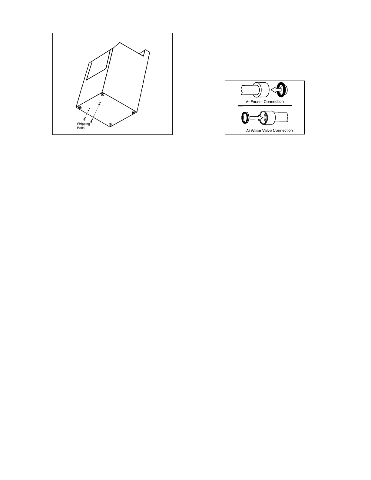
3. Locate the two (2) ½" hex head shipping
bolts extending up through the bottom of
the base (Figure 1-4). The shipping bolts
are near the center of the base toward the
front of the washer. Remove both bolts,
freeing the tub and suspension. Do not
be alarmed should the tub assembly shift
when the last bolt is removed. Some shifting of the tub is normal.
Figure 1-1
Figure 1-3
B. Grasp each loose strap individually and
pull the strap to remove it from the cabinet. Discard the strap (Figure 1-2).
2. Tip washer slightly forward. Loosen rear
leveling leg lock nuts. Tip washer back
slightly to loosen front leveling leg lock
nuts (Figure 1-3).
16008373-01 SECTION 1. GENERAL INFORMATION 1-2
© 1998 Maytag Corporation
Page 9
Turn on the water and check for leaks (Figure
1-5). Note the H and C designations on the
water valve bracket for the Hot and Cold
hoses.
Figure 1-4
4. Slide the washer into position and check
the levelness and stability of the washer.
If necessary, slide the washer out of position to either raise or lower the leveling
leg as required to level and stabilize the
washer securely on all four legs. Slide the
washer back into position to confirm levelness to the floor. When the washer is
level, tighten the locking nuts up against
the base of the washer. This will secure
the leveling legs in place.
5. Install the rubber feet, found in the installation package, on all four (4) legs (Figure
1-3).
6. Pull the drain hose vertically to the drain
strap . Then route the drain hose through
the drain hose strap on the back of the
washer and snap into the plastic hook of
the strap.
7. Install gooseneck end of drain hose into
drain standpipe. Be sure the connection
is not airtight between the drain hose and
standpipe. Standpipe must be at least 24"
high. 36" height is recommended.
8. Connect inlet hoses to water supply using screen washers (found in the installation package) at faucet connections, with
the domed screen facing the faucet. Attach hoses to the faucets and the water
valve.
Figure 1-5
NOTE: Accessory inlet hoses are available in
various lengths, up to 10 feet.
GROUNDING POLARITY CHECKS
The receptacle used for all Maytag products
operating on 120 Volts AC must be properly
grounded and polarized.
The power cord should be equipped with a
three (3) PRONG POLARIZED GROUNDING
PLUG FOR PROTECTION AGAINST SHOCK
HAZARD and should be plugged directly into
a properly grounded and polarized receptacle.
CAUTION: Do not cut or remove the grounding prong from this plug.
It is the responsibility of the person installing
the appliance to ensure it is adequately
grounded and polarized at the point of installation. Local conditions and requirements
should be taken into consideration. In cases
where only a two (2) prong receptacle is available, it is the personal responsibility of the
customer to have it replaced with a properly
grounded and polarized three (3) prong receptacle (Figure 1-6).
16008373-01 SECTION 1. GENERAL INFORMATION
© 1998 Maytag Corporation
1-3
Page 10

Plug power cord into a properly grounded 120
volt AC-approved electrical service. This
must be protected by a dedicated 15 amp fuse
or circuit breaker.
All grounding and wiring should be performed
in accordance with national and local codes.
USE OF ADAPTERS IS NOT RECOMMENDED.
Figure 1-6
SPECIFICATIONS
CAPACITY 3.1 Cubic Feet
CAPACITY 3.1 Cubic Feet
ELECTRICAL 120 volt s, 60 Hz; Requi r es 15 am p circ uit b r eaker or fus ed el ect ri cal
ELECTRICAL 120 volt s, 60 Hz; Requi r es 15 am p circ uit b r eaker or fus ed el ect ri cal
supply. Power cord must be connected to a properly grounded and
supply. Power cord must be connected to a properly grounded and
pol arized o utlet .
pol arized o utlet .
MOTOR Switched Reluctance Motor controlled by a microprocessor motor
MOTOR Switched Reluctance Motor controlled by a microprocessor motor
control board. Motor pulley ratio (motor to spinner RPM) 14 to 1.
control board. Motor pulley ratio (motor to spinner RPM) 14 to 1.
POWER U SAGE Motor Input : During Wash Tumble - 150 Watts
POWER U SAGE Motor Input : During Wash Tumble - 150 Watts
(Wattage readings taken with no clothes in spinner.)
(Wattage readings taken with no clothes in spinner.)
TU MBL ER SPEED Wash Tumble 47-51 RPM
TU MBL ER SPEED Wash Tumble 47-51 RPM
Rin se Tu m ble 47-5 1 RPM
Rin se Tu m ble 47-5 1 RPM
High Speed Spin 800 RPM (± 50 RPM based upon optim um
High Speed Spin 800 RPM (± 50 RPM based upon optim um
WATER USAGE Water pressure should be 20-120 p.s.i. (1.06-8.4 4 kg/cm ) at inlet hose
WATER USAGE Water pressure should be 20-120 p.s.i. (1.06-8.4 4 kg/cm ) at inlet hose
connection. Total water usage is approximately 25 gallons; varies w ith
connection. Total water usage is approximately 25 gallons; varies w ith
cl othe s lo ad. W ater fill in th e spi n b asket w it h no clo thes, m easured
cl othe s lo ad. W ater fill in th e spi n b asket w it h no clo thes, m easured
near the rear seam of the spin basket.
near the rear seam of the spin basket.
WASH LEVEL 3-4 inches
WASH LEVEL 3-4 inches
RINS E LEVEL 4-5 inc hes
RINS E LEVEL 4-5 inc hes
HOSE LENGTHS Four-foot inlet hoses with inlet washers and attaches to water valve.
HOSE LENGTHS Four-foot inlet hoses with inlet washers and attaches to water valve.
DIMENSIONS Cab ine t di mens io ns: 27" (68.58c m) W x 27 ½ ” (69.85 cm ) D x 36"
DIMENSIONS Cab ine t di mens io ns: 27" (68.58c m) W x 27 ½ ” (69.85 cm ) D x 36"
WEIGHT (Approx.) Un car to ned 190lb . (86 kg.) Ap p ro x .
WEIGHT (Approx.) Un car to ned 190lb . (86 kg.) Ap p ro x .
S CREW & BO LT T ORQ UES Bolt, Counter Weight 7in. lbs. (± 3in.lbs)
S CREW & BO LT T ORQ UES Bolt, Counter Weight 7in. lbs. (± 3in.lbs)
Drain hose attaches to pump and will accomm odate 36" dr ain stand
Drain hose attaches to pump and will accomm odate 36" dr ain stand
pipe.
pipe.
(91. 44cm )H.
(91. 44cm )H.
Crat ed 200lb . (91 kg) . Ap p ro x .
Crat ed 200lb . (91 kg) . Ap p ro x .
Bolt, Spin Pulley 30in. lbs (± 3in. lbs)
Bolt, Spin Pulley 30in. lbs (± 3in. lbs)
Bolt, Belt Adjuster 90in. lbs (± 10in. lbs)
Bolt, Belt Adjuster 90in. lbs (± 10in. lbs)
Screw, Front Baffle 25in. lbs (± 3in. lbs)
Screw, Front Baffle 25in. lbs (± 3in. lbs)
Screw, Rear Baffle 18.5in. lbs (± 3in. lbs)
Screw, Rear Baffle 18.5in. lbs (± 3in. lbs)
Clam p, Ho ses 15+ in. lb s
Clam p, Ho ses 15+ in. lb s
Nuts, Spinner Support 18in. lbs (± 3in. lbs)
Nuts, Spinner Support 18in. lbs (± 3in. lbs)
Nuts, Suspension Struts 7in. lbs (± 3in. lbs)
Nuts, Suspension Struts 7in. lbs (± 3in. lbs)
Du ring Rinse Tu m ble - 17 5 Watt s
Du ring Rinse Tu m ble - 17 5 Watt s
To p Spin - 80 0 Wa tt s
To p Spin - 80 0 Wa tt s
spin performance.)
spin performance.)
16008373-01 SECTION 1. GENERAL INFORMATION 1-4
© 1998 Maytag Corporation
Page 11

WASHER CONTROLS
The control system in the Neptune horizontal axis washer generally consists of a timer and
microprocessor-based machine control. These receive input signals and send output signals to
other equipment in the washer, including the motor and motor control, user input switches,
user indicator lights, the door latch and lock assembly, water valves, drain pump, unbalance
switches, dispenser actuator wax motors, a pressure switch, and a tub light.
The machine control has direct control of these items:
- Motor speed and direction, through signals to the motor control.
- Door lock wax motor.
- Hot and cold water valves, with an input signal from the timer and pressure switch.
- Timer motor.
- On Light.
In general, the timer dial is rotated to a desired setting, selects the cycles options using the
option switches, and starts the washer. The machine control reads the inputs from the timer,
option switches and pressure switch then send output signals to the motor control and other
components based upon those inputs. When the machine control has completed its set of
instructions for the specific timer setting, it energizes the timer motor output to advance the
timer to the next increment, reads a new set of input signals from the timer, and acts upon
them. This continues until the cycle is complete. (See Figure 1-7 & 1-8 for a generic representa-
tion of the Neptune washer control system.)
Prior To Series 17
Figure 1-7
16008373-01 SECTION 1. GENERAL INFORMATION
© 1998 Maytag Corporation
1-5
Page 12

Figure 1-8
INPUT DEFINITIONS
DOOR LOCK SWITCH INPUT
When input is present, this is indication the
washer door is locked. The machine controller will not command the spinner to spin faster
than 50 rpm when the input is not present
prior to spin.
END-OF-CYCLE SIGNAL INPUT
The End-of-Cycle Signal Input is energized
through a user input switch on the control
panel. When this is energized and the cycle
has finished, the machine control will sound
the End-of-Cycle signal (See End-Of-Cycle Sig-
nal Output).
FABRIC SELECTION INPUTS
The Fabric Selection Inputs are energized
through a user input switch on the control
panel. The machine control reads these inputs to determine which cycles should be run
when the washer is started.
MAX EXTRACT INPUT
The Max Extract Input is energized through a
user input switch on the control panel. When
input is energized, the machine control will
modify the final spin profile to the max extract profile.
Series 17 & Later
NOTE: If the user selects the Hand Washables
fabric selection, all spins will follow the Max
Extract profile regardless of whether the user
selects the Max Extract option.
OUT-OF-BALANCE INPUT
The Out-of-Balance Input Signal is provided
by three normally-closed switches wired in
sequence. If any of these switches opens due
to an out-of-balance condition, the signal will
be momentarily lost (See Unbalance Control
System).
PRESSURE SWITCH INPUT
The input signal from the Pressure Switch
serves two purposes. It supplies power for
the water valves and provides an indication
to the machine control as to whether the commanded water level has been reached.
When the timer advances into a cycle sequence that calls for water, power is supplied
through the timer to either the wash or rinse
level contacts on the pressure switch. When
the water level in the tub is below the full level
for that setting, the pressure switch circuit is
closed, supplying power for the water valves
to the machine control. When the water level
switch is satisfied, the pressure switch circuit
is opened and power for the water valves is
no longer passed to the machine control. The
16008373-01 SECTION 1. GENERAL INFORMATION 1-6
© 1998 Maytag Corporation
Page 13

machine control interprets this loss of power
as an indication that the water level has
reached the full level.
When the washer is at the "full" level and the
timer is set in a Prewash Tumble, Main Wash
Tumble, Light Wash Tumble, or Rinse Tumble
increment, the machine control will begin the
sequence timing defined for each cycle and
fabric selection setting (See Cycle Sequence
Definitions).
During the drain and spin increments after the
main wash, first rinse, second rinse, and extra rinse increments, the wash side circuit in
the pressure switch is closed. When the water level drains below the wash full level, the
circuit will close and energize the pressure
switch input. The machine control interprets
this signal (not to energize the water valve
outputs) to measure how quickly the washer
is draining. If the machine control commands
a spin speed above 51 rpm before the pressure switch input is energized, it will drop the
speed to 0 rpm and hold there until the pressure switch input is energized. An additional
delay equal to the length of time elapsed will
occur before the pressure switch input is energized. If four minutes elapse without the
pressure switch input being energized, the
machine control will energize the timer motor output to advance the timer into the next
increment and continue with the cycle.
TACH INPUT
The tach input is a feedback signal from the
motor control. It provides eight pulses per
revolution of the switched reluctance motor.
The motor runs at 14 times the speed of the
spinner (14:1 belt ratio). The tach input is used
for monitoring speed and out-of-balance detection (See Tachometer Circuit Diagnostics).
If the machine control commands a motor
speed and direction but does not sense a tach
input signal within five seconds, it will disengage the line relay to stop the washer. This
generally indicates a locked rotor or a malfunction in the motor control.
If the machine control senses a tach input signal when it is not commanding the motor to
run, it will disengage the line relay to stop the
washer.
If the machine control commands a coast
down from final spin speed but is still receiving a tach input signal after two minutes, it
will disengage the line relay to stop the washer.
TEMPERATURE SENSOR INPUT
A thermistor is located in the water valve to
monitor the blended incoming water temperature. The machine control uses this input signal to regulate the water temperature with the
warm or cold wash or warm rinse temperature selections (See Water Valve Outputs).
START/STOP INPUT
The start/stop input is energized by the momentary Push-to-Start/Stop Switch. If this input is energized when a cycle is in progress,
the machine control will disengage the line
TIMER INPUTS
The Timer Input signals are energized through
the cams in the timer. The timer operates with
a 30 second drive cycle and a 5.8 second advance time (See Timer Input Charts).
relay, both water valve output signals, the door
lock wax motor signal, the timer motor output signal, and the on-light output signal. If
this input is energized when a cycle is not in
progress, the machine control will energize
the line relay and begin the cycle sequence as
defined by the timer and user input switches
(See Push-To-Start/Line Relay Operation).
16008373-01 SECTION 1. GENERAL INFORMATION
© 1998 Maytag Corporation
WATER TEMPERATURE INPUTS
The Water Temperature inputs are two separate signals defined by a user input switch on
the control panel. The machine control interprets these signals to determine what the water temperature should be for each fill (See
W ater Valve Outputs).
1-7
Page 14

OUTPUT DEFINITIONS
DOOR LOCKED LIGHT OUTPUT
NOTE: This section applies only to washers
between Series 10 and 16. The "Door Locked"
lights on washers from Series 17 and after are
controlled by a "Door Locked" light switch.
END-OF-CYCLE SIGNAL OUTPUT
The End-Of-Cycle Signal Output is an internal signal on the machine control between the
microprocessor and annunciator. The end-ofcycle signal sounds when a wash cycle is finished and the End-Of-Cycle Input is energized.
The end-of-cycle signal sounds as six pulses
in a 0.35 seconds on, 0.15 seconds off pattern
(See Timer Input Charts).
The Door Locked Light Output signal powers
a 1/3 watt neon indicator lamp on the control
panel. This output is first energized when the
Door Lock Wax Motor Output is energized. At
the end of the cycle, it remains energized for
50 seconds after the Door Lock Switch Input
shuts down. This delay allows the wax motor
to fully retract and unlock the door.
NOTE: The washer will continue to tumble
at the end of cycle until this 50 second delay
is elapsed.
DOOR LOCK WAX MOTOR OUTPUT
The Door Lock Wax Motor Output signal powers a wax motor in the door lock assembly.
The wax motor extends to drive the door lock
system for the washer.
If the washer is started with the timer set in a
Prewash Tumble, Main Wash Tumble, or Light
Wash Tumble increment, the machine control
will wait for three minutes before energizing
the Door Lock Wax Motor Output. This delay
is not affected by water level. This output remains energized until the end of the cycle.
If the washer is started with the timer set in a
Prewash Drain, Bleach Dispense, Spin1, Rinse
Tumble, Spin2, or Spin3 increment, the machine control will energize this output immediately.
ON LIGHT OUTPUT
NOTE: This section applies only to washers
from Series 17 and after. The "Door Locked"
lights on washers between Series 10 and 16
are controlled by a cam on the timer.
The Door Locked Light Output signal powers
a 1/3 watt neon indicator lamp on the control
panel. This output is energized when the
washer is operating in a wash or spin cycle.
Note that the "On" light is not illuminated when
the timer is in a delay increment.
TIMER MOTOR OUTPUT
The machine control energizes the Timer
Motor Output to allow for variable-length
timer increments. If the washer is started with
the timer set in a Prewash Tumble, Main Wash
Tumble, Light Wash Tumble, or Rinse Tumble
increment, the machine control will not begin the cycle sequence timing until the water
level reaches the appropriate level. The Timer
Motor Output is disengaged during this time.
The machine control will stop the washer by
disengaging the line relay if the following occur: 1) The machine control energizes the
timer motor until it senses a timer change. 2)
The timer motor remains energized for five
minutes while the timer inputs change (See
Timer Input Charts).
The machine control will continuously energize the Door Lock Wax Motor Output during
the final (Spin 3) sequence until 30 seconds
before the washer begins to coast from the
final speed.
16008373-01 SECTION 1. GENERAL INFORMATION 1-8
© 1998 Maytag Corporation
Page 15

The machine control counts the number of
rinses during a normal wash cycle. In the first
and second Rinse Tumble increments, the
machine control will energize the Timer Motor Output as soon as the Pressure Switch Input is no longer energized, indicating that the
water has reached the full level. In the third
and fourth (if Extra Rinse is selected) Rinse
Tumble increments, the machine control will
energize the Timer Motor Output 30 seconds
after the Pressure Switch Input is no longer
asserted.
The machine control will energize the Timer
Motor Output when the timer is set into a
Spin1, Spin2, or Spin3 increment 30 seconds
before the end of the spin. It will remain energized until the timer inputs change.
TORQUE OUTPUT
The machine control commands motor speed
and direction through the Torque Output from
the machine control to the motor control.
This output is a pulse width modulated (PWM)
signal (See Section 2: Machine Control).
circuit opens and de-energizes the Pressure
Switch Input on the machine control, which
de-energizes the Water Valve Outputs.
The machine control will read the Water Temperature Sensor Input to determine the
blended water temperature passing through
the water valve. In a warm wash fill, the machine control will first energize both the hot
and cold Water Valve Outputs for five seconds
then de-energize the cold Water Valve Output
and monitor the water temperature. When
the Water Temperature Sensor Input passes
the warm threshold (approx. 20 K Ohms), the
machine control will re-energize the cold output for the remainder of the fill.
In a cold wash fill, the machine control will
first energize only the cold Water Valve Output for five seconds. It then energizes the hot
Water Valve Output and monitors the Water
Temperature Sensor Input until it passes the
cold threshold (approx. 44 K Ohms), when it
de-energizes the Hot Water Valve Output for
the remainder of the fill.
Vcc REFERENCE VOLTAGE OUTPUT
The Vcc Outputs are a reference voltage for
many of the signal outputs. On the machine
control, the Vcc outputs are 24 VDC referenced to the 120 VAC neutral line.
WATER VALVE OUTPUTS
The machine control determines whether the
hot or cold Water Valve Outputs should be energized during each timer increment, but it
only gates the power to the water valves, it
does not directly provide that power. When
the timer is in an increment calling for water,
power passes from the timer to the wash or
rinse level circuit in the pressure switch. When
the water level is below the full level, the pressure switch circuit is closed and the power
passes to the machine control. The machine
control gates the power to the hot and cold
Water Valve Outputs. When the pressure
switch senses that the full level is reached, the
If the user selects a warm rinse temperature,
the machine control will count the rinses and
allow a warm rinse fill only on the third and
fourth (if the user also selects the Extra Rinse
option) rinses. The first two rinses will be cold
only. The machine control does not regulate
water temperature during the rinses.
NOTE: If the user chooses the Easy Care/
Perm Press fabric selection, all rinse fills will
be cold regardless of whether the user also
selected the warm rinse temperature.
16008373-01 SECTION 1. GENERAL INFORMATION
© 1998 Maytag Corporation
1-9
Page 16

CYCLE SEQUENCE DEFINITIONS
NOTE: Refer to Section 2: Timer Input Charts
for information on the timing of each cycle
sequence.
BLEACH DISPENSE
In a Bleach Dispense increment, the machine
control will follow the same tumble pattern
and speed as in a Main Wash Tumble increment.
DELAY
During a Delay increment, the door Lock Wax
Motor Output, Door Locked Light Output (Series 17 and later only), Motor Torque Output,
"On" light (Series 10 to 16 only), and Water
Valve Outputs are de-energized. Note that the
Delay indicator is energized through a cam
on the timer.
EXTRA RINSE
When the user selects the Extra Rinse option,
the spin increment following the third rinse
will follow the Spin2 cycle sequence. The
Timer Motor Output will be energized 60 seconds prior to the end of the spin cycle sequence and will remain energized to advance
the timer through the "Off" increment into the
Rinse Tumble increment.
washers only) will de-energize and the Endof-Cycle Signal will sound if the user had selected the End-of-Cycle Signal option.
LIGHT WASH TUMBLE, MAIN WASH
TUMBLE, and RINSE TUMBLE
The machine control will tumble the washer
at the pattern and speed defined by the Fabric
Selection Inputs (See Cycle Review). Each
tumble will start only after the previous
tumble has completely stopped. The machine
control will reverse the tumble direction after
each pause. The machine control will continue to tumble the washer until the timer inputs change.
In a Light Wash Tumble or Main Wash Tumble
increment, the machine control will de-energize the line relay if the washer continues to
tumble for 29 minutes. This would only occur if the timer were to stall (See Section 1:
Timer Motor Output and Section 2: Timer
Input Chart).
PREWASH DRAIN
During a prewash drain increment, the washer
will tumble at the same speed and in the same
pattern as in the Prewash Tumble increment
for the fabric selection. The Door Lock Wax
Motor Output will be energized during this
increment (See Prewash Tumble).
If the Extra Rinse option is not selected, this
spin will follow the Spin3 cycle sequence and
the Timer Motor Output will be energized 30
seconds prior to the end of the final spin.
IDLE
The Idle increment follows the final spin increment in each cycle. If the Door Lock Switch
Input is energized when the timer advances
into the Idle increment at the end of the cycle,
the machine control will tumble the washer
until 50 seconds after the Door Lock Switch
input is no longer energized. This allows time
for the Door Lock Wax Motor to fully retract.
At this time, the Door Lock Light Output
(washers between Series 10 and 16 only) or
the "On" Light Output (Series 17 and later
16008373-01 SECTION 1. GENERAL INFORMATION 1-10
© 1998 Maytag Corporation
PREWASH TUMBLE
When the timer is set into a Prewash Tumble
increment, the machine control will tumble
at 51 rpm in the following tumble pattern:
Cycle Tumble-Pause Pattern
Cotton/Sturdy 6 sec. - 24 sec.
Easy Care/Perm Press 6 sec. - 24 sec.
Delicates 6 sec. - 24 sec.
Hand Washables 3 sec. - 27 sec.
Page 17

In a Prewash Tumble increment, the machine
control will de-energize the line relay if the
washer continues to tumble for 15 minutes.
This would only occur if the timer were to stall
(See Section 1: Timer Motor Output and Section 2: Timer Input Chart).
MISCELLANEOUS
Door Latch Switch Monitoring
At the end of a cycle, when the timer advances
into the Idle increment, the machine control
will keep the line relay energized until it loses
power when the door latch switch opens. This
guards against the switch contacts welding
closed. In this condition, the machine control will limit what additional cycles can be run
before the door is opened as follows:
Washers between Series 10 and 16
The machine control will allow the washer
to restart only if the user sets the timer
into a Rinse Tumble or Spin3 increment.
Washers from Series 17 and Later
The machine control will allow the washer
to restart in any setting. After that cycle
completes, the user must open the door
before the machine control will allow a
third cycle to start.
Door Lock/Spin Control
control will energize the timer motor output
until the timer inputs change so the washer
can proceed with the cycle.
At the end of spin sequence, if the door lock
switch input is de-energized before the washer
drops below 91 rpm, a hardware circuit on the
machine control will interrupt the torque output signal, which forces the motor control to
0 rpm, and energize the door lock wax motor
circuit to lock the door. This hardware circuit
will keep the door lock wax motor circuit energized until the door lock switch input signal
is energized.
Redistribution
The machine control commands a distribution profile speed ramp from 0 rpm to 85 rpm
at the beginning of each high speed (above
100 rpm) spin. When the washer reaches 85
rpm, the machine control monitors the Tach
Input to determine if the speed varies through
one revolution of the spinner basket. If it
senses a high enough variation in speed (suggesting an out-of-balance condition in the
clothing load), it will drop the spinner speed
to 0 rpm and force a short reverse tumble to
redistribute the clothing load before resuming the spin. If any of the out-of-balance
switches trip and open the out-of-balance input circuit at a speed below 500 rpm, the machine control will also drop the speed to 0 rpm
and force the reverse tumble to redistribute
the clothing load.
When the machine control begins a spin increment, it will not command spin speed
above 51 rpm unless the door lock switch input is energized. At the start of a spin increment, the machine control will drop the speed
to 0 rpm then tumble until the switch is energized. At that point, it will restart the spin sequence. If the door lock switch is not energized after 2 minutes of tumbling, the machine
16008373-01 SECTION 1. GENERAL INFORMATION
© 1998 Maytag Corporation
1-11
Page 18
© 1998 Maytag Corporation
16008373-01 SECTION 1. GENERAL INFORMATION 1-12
The following rules determine the maximum
number of redistribution attempts that will be
allowed in each spin step before the machine
control skips the step and continues with the
spin profile (See Section 2: Unbalance Con-
trol System).
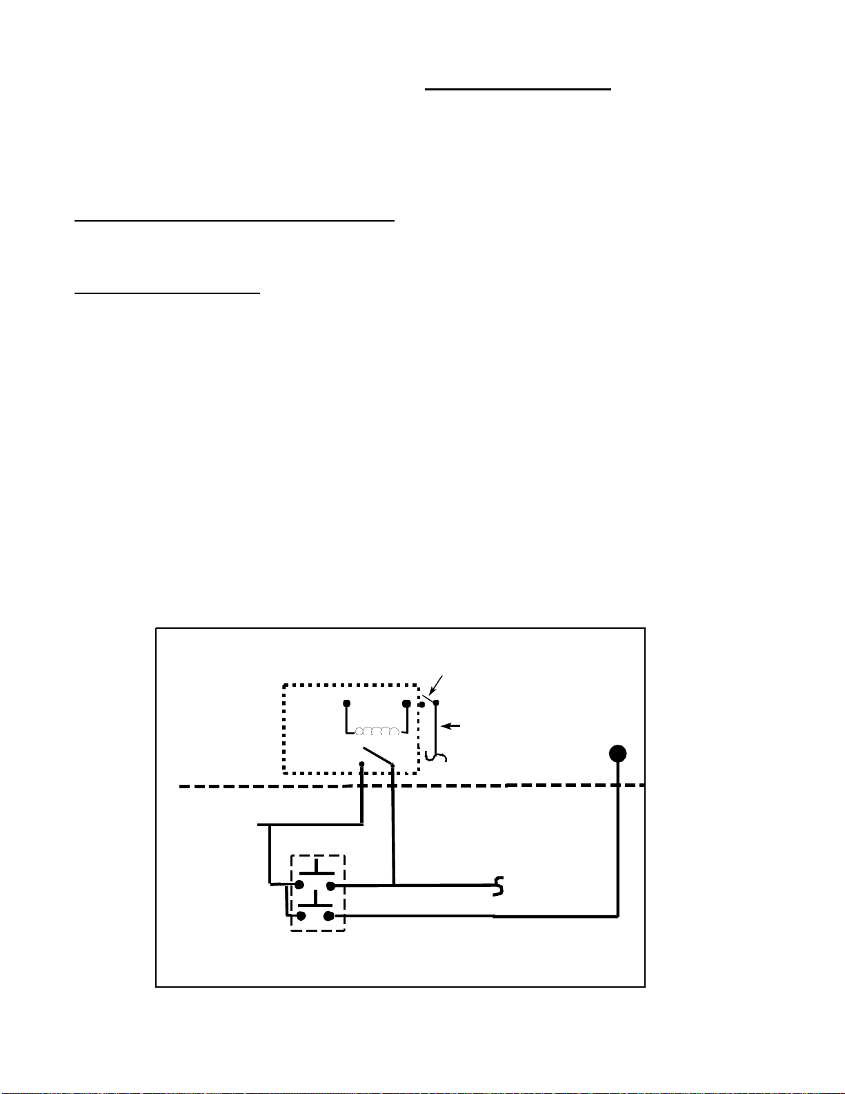
STOPPING THE WASHER
1. With the washer running, power is
supplied to the machine control and
washer from gray wire no. 26 through the
line relay.
2. When the user presses the push-to-start
button, a signal is sent to the machine control through red wire no. 28 telling the
washer to shut down.
3. The machine control opens the internal
logic switch which de-energizes the line
relay.
4. When the user releases the push-to-start
button, power is removed from the machine control and washer (Black wire no.
27).
STARTING THE WASHER
1. With the door closed, press the push-to
start switch.
2. The red no. 28 wire sends a signal to the
machine control to start running.
3. 120 VAC is supplied to the machine control board through black wire no. 27.
4. The machine control closes an internal
switch to energize the line relay.
5. When the push-to-start button is released,
power remains supplied to the machine
control and the washer from gray wire
no. 26 through the line relay.
Push-To-Start Relay Operation
PUSH TO START SWITCH
LINE
RELAY
MACHINE CONTROL BOARD
120 VAC POWER
FRO M MACH INE
CONT ROL BOARD
INTERN AL LOGI C
SWITCH
120 VAC LINE
(When door is
closed)
GY 26
BK 27
RD 28
120 VAC Line
To Timer &
Motor Co ntrol Board
NO
COM
Figure 1-8
Page 19

CYCLE REVIEW
Main Wash Time/Total Cycle Time - Minutes (See Notes).
N on-M ax
Extract Cotton/ Sturdy
Heavy W ash 23 .0 /4 9. 0 20 .0 /4 5.5 20/46.5 Not A pplicable
Normal Wash 17 .0 /4 3. 0 14 .0 /3 9.5 14.0 /4 0.5 No t A pplicable
Light/Quick
Wash
Fin al Sp in
(RPM /M i n )
Max Extract
Cycles Cotton/ Sturdy
Heavy W ash 23 .0 /4 6. 0 20 .0 /4 1.5 2 0 .0 /4 2. 0 20 .0 /4 3 .0
Normal Wash 17 .0 /4 0. 0 14 .0 /3 5.5 1 4 .0 /3 6. 0 14 .0 /3 7. 0
Light/Quick
Wash
Fin al Sp in
(RPM /M i n )
11 .0 /3 7.0 8.0/33.5 7.0/34 .5 Not A pplicable
800/3.5 60 0/3.0 500/4.5 No t A pplicable
11 .0 /3 4.0 8.0/29.5 8 .0 /3 0.0 8 .0 /3 1.0
800/4.0 60 0/3.5 500/5.0 500/5.0
Easy Care/
Perm Press Delicates
Easy Care/
Perm Press Delicates
Hand
Washables
Hand
Washables
Notes:
1. The main wash times listed include 2 minutes of bleach fill and tumble time.
2. The total cycle times are approximate and will vary based on water fill times, due to types of
clothing loads, available water pressure and the time for the door lock system to retract at
the end of the cycle.
3. The main wash time is affected significantly if the machine control detects an excessive
amount of suds. The washer will go into a suds reduction routine, consisting of a series of
additional rinse and partial drain cycles to reduce the suds present (See Troubleshooting &
Diagnosis - Clothes Wet at End of Spin).
Tumble Pattern - Number of seconds tumbling/Number of seconds of pause between tumbles.
Cotton/ Sturdy Easy Care/
Perm Press
7/3 5/ 3 6/2 4 3/27
De licates Hand W ashab les
16008373-01 SECTION 1. GENERAL INFORMATION
© 1998 Maytag Corporation
1-13
Page 20

GENERAL COMPONENT EXPLODED VIEW
16008373-01 SECTION 1. GENERAL INFORMATION 1-14
© 1998 Maytag Corporation
Page 21

SECTION 2. ELECTRICAL COMPONENTS & TESTINGSECTION 2. ELECTRICAL COMPONENTS & TESTING
SECTION 2. ELECTRICAL COMPONENTS & TESTING
SECTION 2. ELECTRICAL COMPONENTS & TESTINGSECTION 2. ELECTRICAL COMPONENTS & TESTING
ELECTRICAL TEST EQUIPMENTELECTRICAL TEST EQUIPMENT
ELECTRICAL TEST EQUIPMENT
ELECTRICAL TEST EQUIPMENTELECTRICAL TEST EQUIPMENT
The equipment required to service Maytag
products depends largely upon the conditions
you encounter. Locating a malfunction will
DescriptionDescription
Description
DescriptionDescription
Analog Test Meter 200 00005
Digital Test Meter 20001001
Clamp-On Ammeter 20000002
AC Voltage Sensor 20000081
Analog Test MeterAnalog Test Meter
Analog Test Meter
Analog Test MeterAnalog Test Meter
can be used to check
for open or closed
circuits, measure resistance, AC and DC volts,
and temperature.
often require the use of electrical testing
equipment such as:
Part NumberPart Number
Part Number
Part NumberPart Number
Clamp-On AmmeterClamp-On Ammeter
Clamp-On Ammeter
Clamp-On AmmeterClamp-On Ammeter
can be used to detect
shorts. Overloads on
the circuit
breaker or fuse
can be traced
to either the
washer or circuit
breaker by checking the washer
current draw.
AC Voltage SensorAC Voltage Sensor
Digital Test MeterDigital Test Meter
Digital Test Meter
Digital Test MeterDigital Test Meter
can be used to check for
open or closed circuits,
measure resistance,
AC and DC volts,
and temperature.
16008373-01 SECTION 2. ELECTRICAL COMPONENTS & TESTING
© 1998 Maytag Corporation
AC Voltage Sensor
AC Voltage SensorAC Voltage Sensor
can be used to alert you if
AC voltage is present so proper
safety precautions can be observed.
The tip of the sensor will glow
bright red if voltage is between
110-600 volts AC.
2-12-1
2-1
2-12-1
Page 22

ELECTRICAL TESTS
Water Valve Test
Warning - Always shut off
electrical power to the
unit before beginning any
service repair procedures.
Grounded Components
When performing service diagnostics, replacements and repairs, always check to determine whether all ground wires linking
panel and components are reattached if
removed.
Voltage Checks
Generally, these checks will consist of taking
readings at the wall receptacle to determine
the availability of voltage to the product. Voltage checks on individual components of a
product are not recommended due to the
possibility of electrical shock. Component part
testing is best accomplished through continuity checks with an Appliance Test Meter
(See Electrical Test Equipment).
NOTE: Use of the meter on voltage higher
than the indicated range may cause permanent damage to the meter. To prevent damage, first select the highest range and then
lower the range for readings which fall within
the lower scale.
Set up meter for use as follows:
1. Turn selector knob to desired meter function and appropriate range.
2. Plug black lead into socket marked black
(-).
Check the water valve for electrical continuity. This check should be made with the elec-
trical supply disconnected from the washer.
Remove the wire harness from the water valve
terminals and place the ohm meter probes on
the terminals of the water valve. The water
valve solenoid coil should have a resistance
between 500-1000 ohms. If no ohms are
shown on the display of the electrical test
meter, the solenoid coil has an open winding
and the valve should be replaced. The thermistor in the water valve changes in resistance
in direct relationship to water temperatures.
To monitor the performance of the thermistor,
run a partial hot water fill and check the ohm
resistance of the thermistor circuit. Then, run
a cold water fill and measure the resistance
again. There should be a notable difference
in the resistance readings. To check the ohm
resistance, pull the P2 wire harness connector off the machine control and locate the
P2(5) and P2(6) leads in the connector
(Figure 2-3).
Wax Motor Check - Door Lock
Mechanism
Check the wax motor for proper resistance.
This check should be made with the electrical
supply disconnected from the washer. Re-
move the wire harness from the wax motor
terminals and place the ohm meter probes on
the terminals of the wax motor. The wax motor should have a resistance of approximately
1900 ohms at room temperature. To check
wax motors through console, see section:
Machine Control page 2-5.
3. Plug red lead into socket marked red (+).
4. Place test leads into receptacle to determine voltage available.
16008373-01 SECTION 2. ELECTRICAL COMPONENTS & TESTING
© 1998 Maytag Corporation
2-2
Page 23

Timer & Console SwitchesTimer & Console Switches
Timer & Console Switches
Timer & Console SwitchesTimer & Console Switches
The timer is located in the control console on
the back. It is composed of a series of switches
driven by an electric timer motor. The timer
motor rotates a pinion gear which then rotates
internal cams. As the cams rotate, they lift
and drop various switch contacts which ride
on the cam. The internal switches provide
cycle sequence or step inputs to the machine
control to control the pump, dispenser wax
motors, delay light, ON light and timer motor .
The timer wire harness connector can be
pulled and the individual contacts for the various circuits can be checked with an ohm
meter. As illustrated, timer contact for the
drain pump is 14T
(Figure 2-1).(Figure 2-1).
(Figure 2-1).
(Figure 2-1).(Figure 2-1).
CC
C
TTTCC
TT
Figure 2-2Figure 2-2
Figure 2-2
Figure 2-2Figure 2-2
BB
B
BB
motor windings. The following chart can be
used for checking other components via the
timer wire harness connector.
Figure 2-1Figure 2-1
Figure 2-1
Figure 2-1Figure 2-1
Y ou can identify the wire for the drain circuit
(Figure 2-2)(Figure 2-2)
(Figure 2-2)
(Figure 2-2)(Figure 2-2)
by tracing down the side of the
connector to contact 14, and across to align
with column T.
Contact 8B in the connector is a direct contact to the neutral leg of the timer . When an
ohm meter probe is placed into the 14T connection and the other probe is placed into 8B,
an ohm reading of the complete drain circuit
can be performed. The drain circuit should
have a resistance of approximately 18 ohms.
This is the resistance reading of the pump
Description Connector Connector Ohms
Pump
Motor
Bleach Wax
Motor
Softener
Wax Motor
Timer
Motor
Timer Input ChartsTimer Input Charts
Timer Input Charts
Timer Input ChartsTimer Input Charts
14T 10B 18
2B 10B 950-1100
2T 10B 950-1100
10T 10B 5000
As stated previously, the machine control
board receives inputs from the timer monitor
where the timer is in the cycle. The machine
control board accomplishes this by routing
four circuits through the timer. Two of the circuits (1A & 1B) are supplied with 120 V AC and
the other two circuits (2A & 2B) are 24 VDC.
The voltages for the four circuits is shown on
the timer chart of the electrical schematic
enclosed in the washer console.
16008373-01 SECTION 2. ELECTRICAL COMPONENTS & TESTING
© 1998 Maytag Corporation
2-32-3
2-3
2-32-3
Page 24

Software in the machine control board specifically monitors the timer input circuits to
determine where the timer is in all the wash cycles and will rapidly advance the timer to
OPEN and break contacts in the timer. The timer is solely used as an off-board set of
relay switches. Note: The timer motor is hard wired to timer cams 10T and 10B in the
timer.
TIMER 1A
(120 VAC)
CYCLE SEQUENCE
PREWASH TUMBLE 0 1 1 0
PREWASH DRAIN 1 1 1 0
MAIN WASH TUMBLE 0 1 0 0
LIGHT WASH TUMBLE 1 1 0 0
BLEACH DISPENSE 1 0 1 0
RINSE TUMBLE 1 0 0 1
SPIN 1 0 0 1 0
SPIN 2 0 0 0 1
SPIN 3 0 1 0 1
EXTRA RINSE 1 1 0 1
DELAY 1 0 0 0
PK19/P7(8)
TIMER 1B
(120 VAC)
YL16/P7(7)
TIMER 2A
(24 VDC)
PU17/P3(3)
TIMER 2B
(24 VDC)
BU18/P3(5)
IDLE 0 0 0 0
Key: 0 = Input Signal Not Asserted 1= Input Signal Asserted
There are conditions under which the machine control will shut the cycle down if the
timer does not advance.
- During Extra Wash/Prewash: If the timer inputs do not change away from Prewash
Tumble for 15 minutes, the machine control will open the line relay.
- During Main Wash: If the timer inputs do not change for 29 minutes, the machine
control will open the line relay.
- During any increment when the machine control energizes the timer motor until it
sees the timer inputs change: If the timer inputs do not change for 5 minutes with the
timer motor continuously energized, the machine control will open the line relay.
These varying delays are to allow the washer to progress through several increments
where the timer inputs normally do not change. In these cases, the machine control
energizes the timer motor for 30 seconds, which is its advance time. It does not look for
a timer input change.
16008373-01 SECTION 2. ELECTRICAL COMPONENTS & TESTING
© 1998 Maytag Corporation
2-4
Page 25
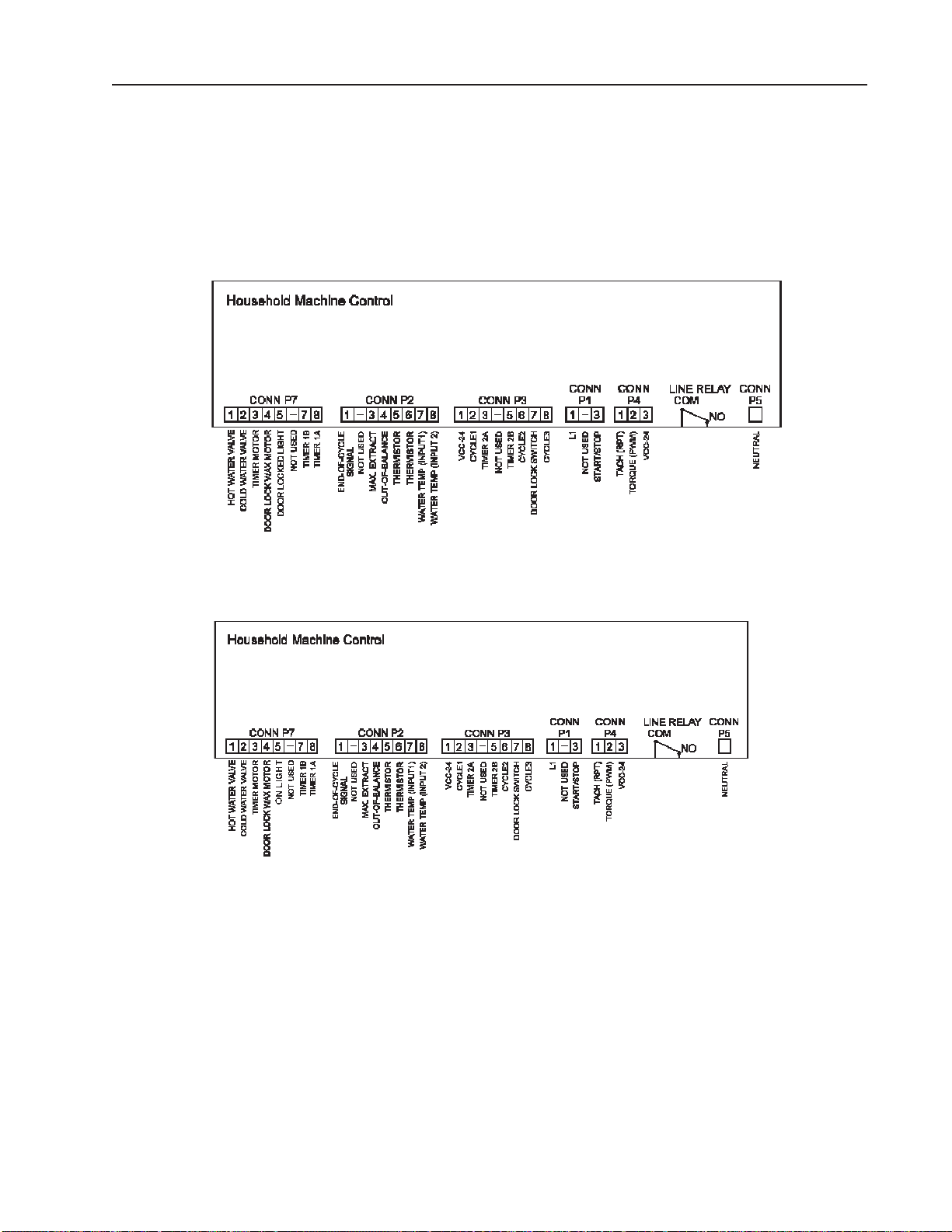
Machine ControlMachine Control
Machine Control
Machine ControlMachine Control
The machine control microprocessor board is located in the control console, mounted to the
rear panel. The board receives input from the timer , door latch and lock switches, and unbalance and selector switches on the console. It also communicates with the motor control board
to facilitate the various cycles and drive the motor for optimum perfor mance. Torque and
speed of the motor are monitored through the motor control board.
Prior to Series 17Prior to Series 17
Prior to Series 17
Prior to Series 17Prior to Series 17
Figure 2-3Figure 2-3
Figure 2-3
Figure 2-3Figure 2-3
Series 17 and AfterSeries 17 and After
Series 17 and After
Series 17 and AfterSeries 17 and After
Figure 2-3bFigure 2-3b
Figure 2-3b
Figure 2-3bFigure 2-3b
Both incoming and exiting voltage are monitored through the machine control board and the
surrounding circuitry . The following table lists the voltages for the various terminals on the
microprocessor board. If proper voltage is not present, check switches and wiring for any
loose connections or open circuits by disconnecting the power supply and performing continuity checks of individual circuits.
Line Relay Connector Comm (Gray wire), L1 output is Line Relay Connector Comm (BlackLine Relay Connector Comm (Gray wire), L1 output is Line Relay Connector Comm (Black
Line Relay Connector Comm (Gray wire), L1 output is Line Relay Connector Comm (Black
Line Relay Connector Comm (Gray wire), L1 output is Line Relay Connector Comm (BlackLine Relay Connector Comm (Gray wire), L1 output is Line Relay Connector Comm (Black
wire).wire).
wire).
wire).wire).
NOTE:NOTE:
NOTE:
NOTE:NOTE:
Connector P5 is Neutral input and L1 input is the Connector P5 is Neutral input and L1 input is the
Connector P5 is Neutral input and L1 input is the
Connector P5 is Neutral input and L1 input is the Connector P5 is Neutral input and L1 input is the
To check voltages from the board, turn timer dial to a wash cycle and press the start/off button.
This will activate the L1 relay board and apply power on the machine control.
16008373-01 SECTION 2. ELECTRICAL COMPONENTS & TESTING
© 1998 Maytag Corporation
2-52-5
2-5
2-52-5
Page 26

FUNCTION
MACHINE
CONTROL
BOARD
TERMINAL/WIRE
MACHINE
CONTROL
BOARD
TERMINAL/WIRE
VOLTAGEAPPROX.
(When Activated)
TIMER
CONTACT
Permanent Press
(Fabric Switch)
Delicates
(Fabric Switch)
Hand Wash
(Fabric Switch)
Cotton/Sturdy
(Fabric Switch)
Signal ON/OFF
(Options Switch)
Extra Rinse
(Options Switch)
Max Extract
(Options Switch)
Push To Start
Switch
(When pressed)
Unbalance
Control
P5 (WH11) P3/2 (PK 37) 24 VDC Not Involved
P5 (WH11) P3/6 (OR 38) 24 VDC Not Involved
P5 (WH11) P3/8 (BR 39) 24 VDC Not Involved
P5 (WH 11)
P5 (WH 11)
P5 (WH 11)
P5 (WH 11) P2/1 (PU 21) 24 VDC - ON
P5 (WH 11) P7/8 (PK 19) 120 VAC 12B, 6B,8T
P5 (WH 11) P2/3 (YL 20) 24 VDC Not Involved
P5 (WH 11) P1/3 (RD 28) 120 VAC Not Involved
P5 (WH11) P2/4 (OR 40) 24 VDC Not Involved
P3/2 (PK 37)
P3/6 (OR 38)
P3/8 (BR 39)
0 VDC
0 VDC
0 VDC
0 VDC - OFF
Not Involved
Not Involved
Door Lock - Spin P3 (1) P3/7 (YL 36) 24 VDC Not Involved
Motor Control &
Machine Control
Hot Water Valve P5 (WH11) P7/1 (OR7) 120 VAC or
Cold Water Valve P5 (WH11) P7/2 (BU 9) 120 VAC or
Door Lock Wax
Motor
Bleach Wax
Motor
Softener Wax
Motor
Delay Light P5 (WH11) Not Involved 120 VAC 4T
On Light
(Series 17)
P5 (WH11) LINE RELAY COM
(BK 27 or BK1)
P5 (WH11) P7/4 (BR 14) 120 VAC Not Involved
P5 (WH11) Not Involved 120 VAC 2T
P5 (WH11) Not Involved 120 VAC 2B
P5 (WH11) P7/5 (RD 3) 120 VAC Not Involved
120 VAC Not Involved
Not Involved
500-1000 Ohms
Not Involved
500-1000 Ohms
16008373-01 SECTION 2. ELECTRICAL COMPONENTS & TESTING
© 1998 Maytag Corporation
2-6
Page 27

DRIVE MOTORDRIVE MOTOR
DRIVE MOTOR
DRIVE MOTORDRIVE MOTOR
The drive motor is a switched reluctance type
motor. The basic operating principle of the
switched reluctance motor is direct magnetic
attraction between the stationary electromagnetic coils (stator) and a specially configured
rotor or armature
comprised of stacked plates or laminations
mounted on a center shaft. The shape of
these laminations are characteristic of the
switched reluctance motor. The rotor, when
viewed from the end of the rotor, has "teeth"
much like a gear . These "teeth", or pole pieces,
are pulled as the result of direct current power
through the stator coils.
(Figure 2-4)(Figure 2-4)
(Figure 2-4)
(Figure 2-4)(Figure 2-4)
. The rotor is
The following illustration shows the motor
terminals for each of the coils involved. The
letters with positive and negative symbols indicate the motor phase circuitry of the
terminals.
Motor Harness Connector
Figure 2-5Figure 2-5
Figure 2-5
Figure 2-5Figure 2-5
Figure 2-4Figure 2-4
Figure 2-4
Figure 2-4Figure 2-4
Multiple stator coils are positioned around the
rotor and are connected in three different
phased "sets" of paired coils.
Magnetic attraction causes the rotor poles to
turn toward the coils. The electronic motor
control board switches the magnetic field off
as the rotor pole piece approaches; then,
turns on another set of coils further ahead. It
is this switching action of motor phases that
determines direction and rotational speed of
the rotor (and shaft). The motor control board
changes the 120 V AC voltage line input to 170
VDC, and distributes the current phases to the
stator coil sets in sequence to the drive
motor.
Refer to section titled
identification of A, B and C terminal/harnesses
(Figure 2-6). (Figure 2-6).
(Figure 2-6).
(Figure 2-6). (Figure 2-6).
for harness identification.
MOTOR CONTROL BOARDMOTOR CONTROL BOARD
MOTOR CONTROL BOARD
MOTOR CONTROL BOARDMOTOR CONTROL BOARD
The motor control board r eceives 120 VAC
voltage from the line cord and distributes DC
voltage to the drive motor. The motor control converts the voltage from single phase to
3 phase for the drive motor .
Another purpose of the motor control is to
monitor the drive motor speed through a tachometer circuit linking the motor control
board to a tachometer on the drive motor. This
is a 3-wire circuit comprised of a Black, Blue
and White wire harness. Failure of this circuit
will cause the motor to start jerking in place
or accelerate rapidly for up to 5 seconds. This
occurs whenever the tachometer in the drive
motor is trying to locate the proper shutter
and sensor sequence. For example, if the tachometer signal is lost from the motor control to the machine control just prior to spin,
the motor will ramp up for 5 seconds then
stop.
Also, see the wiring schematic
Motor ControlMotor Control
Motor Control
Motor ControlMotor Control
for board
16008373-01 SECTION 2. ELECTRICAL COMPONENTS & TESTING
© 1998 Maytag Corporation
2-72-7
2-7
2-72-7
Page 28
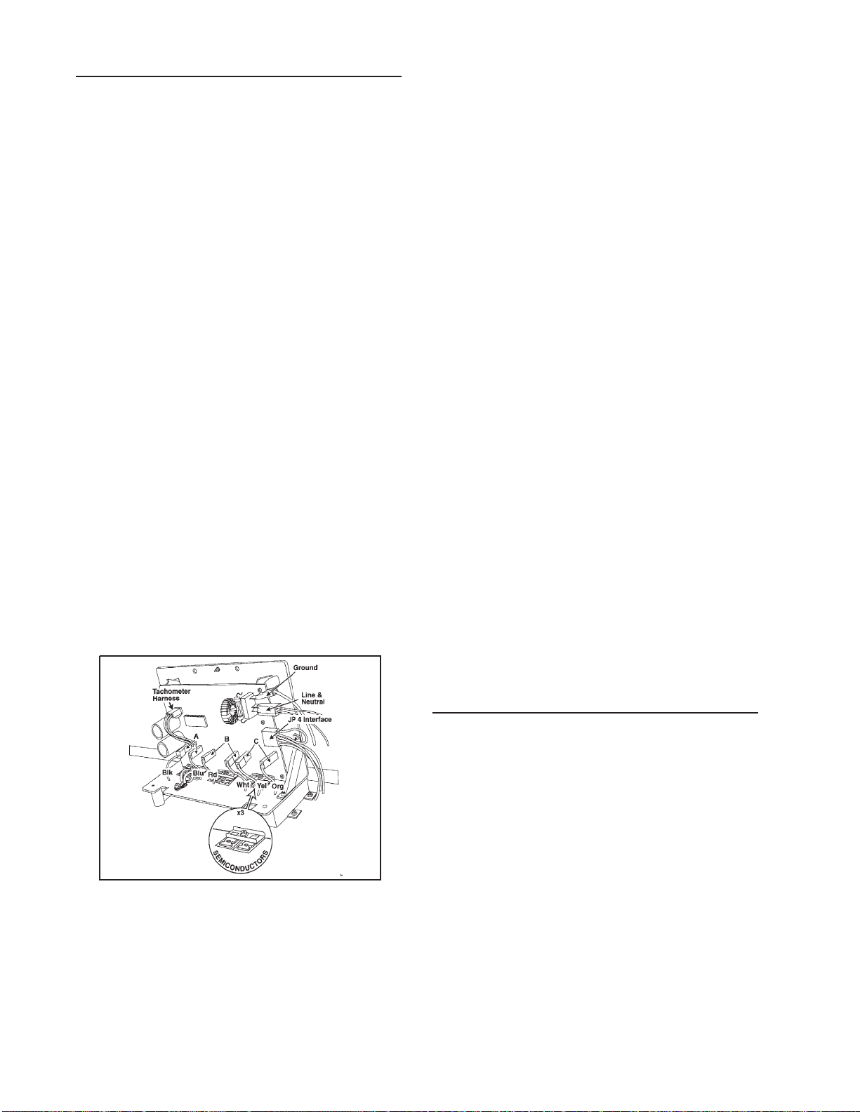
© 1998 Maytag Corporation
16008373-01 SECTION 2. ELECTRICAL COMPONENTS & TESTING
2-82-8
2-82-8
2-8
Motor & Motor ContrMotor & Motor Contr
Motor & Motor ContrMotor & Motor Contr
Motor & Motor Contr
ol Tol T
ol Tol T
ol T
estest
estest
est
1. Set the timer knob into the delay increments.
2 . Press the push-to-start switch to start the
washer in the delay mode. Confirm the
delay light is ON.
3. Check for 120 VAC between the L and N
terminals (black wire no.27 and white wire
no. 13) on the motor control board. If not
present, check wiring between the machine control and the motor control
boards.
4 . Unplug the washer power cord. Test cord
to the same board terminals.
5. Remove JP4 Interface connector wire harness on front end of motor control board.
6. Plug the washer power cord into a 120 V AC
power source. The motor control will immediately execute a test routine and the
motor should run, rotating the spinner at
50 rpm.
6.
If the motor runs,If the motor runs,
If the motor runs,If the motor runs,
If the motor runs, and the spinner rotates
at the proper RPM speed, the problem lies
outside of the motor and motor control
circuit. Disconnect power to the washer
and reconnect the JP4 Interface connector to the motor control.
7.
If the motor does not run:If the motor does not run:
If the motor does not run:If the motor does not run:
If the motor does not run:
A. Check the 10-amp fuse located on the
control board, either visually or with an
ohm meter . If bad, completely replace motor control/wire harness assembly
(Figure 2-6).(Figure 2-6).
(Figure 2-6).(Figure 2-6).
(Figure 2-6).
Figure 2-6Figure 2-6
Figure 2-6Figure 2-6
Figure 2-6
B. If the fuse is functioning, visually check
the six semiconductors on the heat sink
for any damage. If damaged, replace motor control/wire harness assembly complete and check motor windings for damage
(See Drive Motor). (See Drive Motor).
(See Drive Motor). (See Drive Motor).
(See Drive Motor).
Replace motor if
necessary
(Figure 2-6) (Figure 2-6)
(Figure 2-6) (Figure 2-6)
(Figure 2-6)
..
..
.
C. If fuse and semiconductors show no
visible damage, perform the motor phase
test.
8. Unplug the washer power cord and replace motor control board connector JP4
when finished.
Motor Phase TMotor Phase T
Motor Phase TMotor Phase T
Motor Phase T
estest
estest
est
It is possible for the motor to still run under
light loads when one of the phases of the
motor is nonfunctional. One possible symptom would be a "growling" noise from the
motor . Torque is decreased when the motor
is out of phase. This could result in a customer complaint that the load is not spinning
out properly or it does not tumble consistently
with a large load
(See Section 3: T(See Section 3: T
(See Section 3: T(See Section 3: T
(See Section 3: T
rr
rr
r
ouble-ouble-
ouble-ouble-
ouble-
shooting).shooting).
shooting).shooting).
shooting).
Page 29

To gain access to the motor control board
terminals (Figure 2-6):
windings check (See Motor Windings
Check).
1. Disconnect power to the washer prior to
testing.
2. Remove the two screws securing the motor control assembly to the base. Unsnap
the two twist-lock wire ties restraining the
motor to the motor control board harness
base.
3. Remove the green ground wire, line & neutral wires and the JP4 connector from the
motor control board.
4. Carefully lift the front end of the motor
control board to disengage the rear locking tabs from the slots in the base. Slowly
drag the motor control board, with motor
harness attached, toward the front of the
washer and place in front of the washer.
5. Remove the screw securing the splash
shield covering the face of the motor control board. Pivot the splash shield with top
screw in the motor control board metal
frame, allowing the plastic shield to become an electrical shield between the
motor control board and the base.
6. Reconnect the ground wire, line 1 and neutral wires. Leave the JP4 connector off the
board (Figure 2-6).
10. Check Phase B by disconnecting the white
or red wire at the motor control board. If
the motor operates with a slight growling
sound, phases A and C are operating correctly. Reconnect phase B and test with
phase A disconnected. If the motor does
not run properly, phase A or C is not functioning. Perform the motor windings
check (See Motor Windings Check).
Motor Windings Check
1. Disconnect power to the unit.
2. Remove each pair of phase wires from the
motor control and perform an ohm check
of each wire leading to the motor. Each
wire pair should show 2-3 ohms resistance
(Figure 2-5).
2. There should be no continuity between
any of the terminals and the frame of the
motor.
3. Check that all six motor terminals are secure and at the same height in the connector housing. Replace motor if terminals are pressed into the motor.
7. Place the timer knob into the delay
increments.
8. Plug the power cord into the wall socket
and press the push-to-start button.
tor onto the motor. Reassemble the drip
shield cover onto the motor control.
5. Reposition the motor control into the
washer when finished. Make sure the two
screws and the twistlock wire ties are fas-
4. Remount the six-position motor connec-
9. Check Phase C by disconnecting the yel-
tened properly to the wire harness.
low or orange wire at the motor control
board. If the motor operates with a slight
growling sound, phases A and B are operating correctly. Reconnect phase C and
test with phase B disconnected. If the
motor does not run properly, phase A or
B is not functioning. Perform the motor
16008373-01 SECTION 2. ELECTRICAL COMPONENTS & TESTING
© 1998 Maytag Corporation
2-9
Page 30
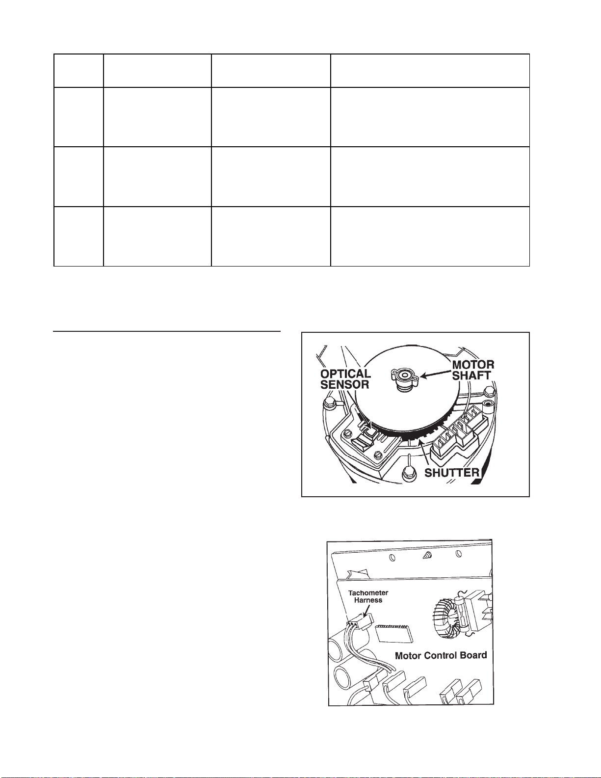
PHASE WIRE COLORS MOTOR CONDITION RESULT/SOLUTION
C Yellow or Orange Runs
Does Not Run
B White or Red Runs
Does Not Run
A Black or Blue Runs
Does Not Run
TT
achometer Cirachometer Cir
T
achometer Cir
TT
achometer Cirachometer Cir
The tachometer system of the motor is comprised of a plastic wheel, called a shutter , and
an optical sensor
mounted to the end of the motor shaft under
the plastic endbell covering of the motor . The
edge of the shutter resembles a "picket fence"
with different size "pickets." The pattern consists of six different "pickets" which are repeated eight times. An optical sensor is
mounted to one side of the shutter and monitors the "pickets" as they pass through the
sensor .
cuit Diagnosticscuit Diagnostics
cuit Diagnostics
cuit Diagnosticscuit Diagnostics
(Figure 2-9).(Figure 2-9).
(Figure 2-9).
(Figure 2-9).(Figure 2-9).
The shutter is
-Phases A&B are operating correctly.
(Check Phase A and B)
-Phase A or B is non-functional.
(See Step 10)
-Phases A&C are operating correctly.
(Check Phase A and C)
-Phase A or C is non-functional.
(See Step 10)
-Phases B&C are operating correctly.
(Check Phase B and C)
-Phase B or C is non-functional.
(See Step 10)
Figure 2-9Figure 2-9
Figure 2-9
Figure 2-9Figure 2-9
As the "pickets" pass through the sensor field,
signals are generated and transmitted to the
motor control board through the tachometer
wire harness
16008373-01 SECTION 2. ELECTRICAL COMPONENTS & TESTING
(Figure 2-10 and 2-11).(Figure 2-10 and 2-11).
(Figure 2-10 and 2-11).
(Figure 2-10 and 2-11).(Figure 2-10 and 2-11).
© 1998 Maytag Corporation
Figure 2-10Figure 2-10
Figure 2-10
Figure 2-10Figure 2-10
2-102-10
2-10
2-102-10
Page 31

The following table indicates voltage checks
of the tachometer harness between the motor and motor control board.
Figure 2-11Figure 2-11
Figure 2-11
Figure 2-11Figure 2-11
The motor control monitors the signals and
communicates this information to the machine control. The purpose of this signal is to
tell the motor when to energize each winding
in the motor and to tell the machine control
the actual motor speed.
Note:Note:
If the machine control board does not If the machine control board does not
Note:
If the machine control board does not
Note:Note:
If the machine control board does not If the machine control board does not
receive an input signal from the motor con-receive an input signal from the motor con-
receive an input signal from the motor con-
receive an input signal from the motor con-receive an input signal from the motor control/tachometer circuit (JP4 connector), thetrol/tachometer circuit (JP4 connector), the
trol/tachometer circuit (JP4 connector), the
trol/tachometer circuit (JP4 connector), thetrol/tachometer circuit (JP4 connector), the
motor speed will rapidly accelerate for 5 sec-motor speed will rapidly accelerate for 5 sec-
motor speed will rapidly accelerate for 5 sec-
motor speed will rapidly accelerate for 5 sec-motor speed will rapidly accelerate for 5 seconds then shut down. The machine controlonds then shut down. The machine control
onds then shut down. The machine control
onds then shut down. The machine controlonds then shut down. The machine control
will sense a "locked rotor" condition and thewill sense a "locked rotor" condition and the
will sense a "locked rotor" condition and the
will sense a "locked rotor" condition and thewill sense a "locked rotor" condition and the
motor will stop. If the motor control doesmotor will stop. If the motor control does
motor will stop. If the motor control does
motor will stop. If the motor control doesmotor will stop. If the motor control does
not rnot r
eceive an input signal freceive an input signal fr
not r
eceive an input signal fr
not rnot r
eceive an input signal freceive an input signal fr
the motor will "jerk" for 5 seconds then shutthe motor will "jerk" for 5 seconds then shut
the motor will "jerk" for 5 seconds then shut
the motor will "jerk" for 5 seconds then shutthe motor will "jerk" for 5 seconds then shut
down.down.
down.
down.down.
om the motorom the motor
om the motor
om the motorom the motor
,,
,
,,
1 . Inspect the motor control wire harness for
integrity of the connections on both ends.
The harness is comprised of a White, Blue
and Black wire.
Tachometer
Wire Checks
White to Black
(From Motor
Control)
White To Black
(From Motor
Control)
White To Black
(From Motor
Control)
Blue to Black
(From Drive
Motor)
Blue to Black
(From Drive
Motor)
UNBALANCE CONTROL SYSTEMUNBALANCE CONTROL SYSTEM
UNBALANCE CONTROL SYSTEM
UNBALANCE CONTROL SYSTEMUNBALANCE CONTROL SYSTEM
Voltage Found
11 VDC
(± 2.5 VDC)
0 VDC
+ 13 VDC or
<9 VDC
No change in
DC volts as
motor is turned
slowly
Voltage
changes from 0
- 5 VDC volts as
motor is turned
slowly.
Condition Of
Component
Good Motor
Control Board
Bad Motor
Control Board
Bad Motor
Bad Motor
Good Motor
The unbalance control system is comprised
of the inertial switch, outer tub displacement
switch, strut displacement switch and a cabinet vibration sensor mounted to the machine
control board. The three switches are wired
in series on a 24 VDC circuit, monitored by
the machine control board. The sensor is
mounted on the machine control board.
2 . Set the washer into the Delay Wash cycle
and press the start/off button. The unit will
start without activating the motor. Leave
the tachometer harness on the motor control and insert the meter probes into the
back side of the tachommeter harness.
Software in the machine control board will
begin monitoring the switches when the spin
speed reaches 90 rpm. The inertial unbalance
switch monitors outer tub vibrations above
150 rpm. Inside the door is a cabinet vibration absorber designed to counter the vibration of the tub and serve as a tuned absorber
for the whole washer .
16008373-01 SECTION 2. ELECTRICAL COMPONENTS & TESTING
© 1998 Maytag Corporation
2-112-11
2-11
2-112-11
Page 32

Whenever a displacement switch is tripped,
the machine stops and redistributes the
clothes load. This involves a three (3) second
pause, followed by a five (5) second reverse
tumble (47-49 rpm) to redistribute the clothes
load. The washer will pause again for three
(3) seconds, then start the distribution profile
again. To redistribute the load, the machine
tumbles the load (50-90 rpm) and again attempts to pass through critical (about 150
rpm). The machine will try to redistribute
twice as the washer attempts to spin at 800
rpm.
Tub Displacement Switch
The tub displacement switch is located on the
upper right hand side of the outer tub, below
the top concrete weight, between the outer
tub and the cabinet. The switch senses the
outer tub touching the cabinet side as the
machine passes through critical. When this
switch is tripped, the machine stops and redistributes the load.
Testing the Tub Displacement Switch:
Once the load is properly redistributed and
the speed reaches above 500 rpm, the inertial
switch and cabinet vibration sensor are used.
If the inertial switch or sensor is activated, the
washer will drop in spin speed. This is based
upon the speed at which switch activation
takes place. See Figure 2-12 outlining the spin
speed categories and the corresponding reduced speeds. If the switches are not activated, the final spin speed will reach a maximum of 850 rpm and then drop to find the
optimum performance level, based upon
readings taken by the cabinet vibration sensor. Consumers may be confused by the upand-down cycling of the motor. However, the
machine is searching for the optimal speed
performance.
RPM FUNCTION
47 ...........................Tumble
47-85 .......................Distribution
90-250 .....................Accelerate Through
Critical
250-499..................Accelerate Through
Critical
500-575..................High Speed Acceleration
- WILL DROP TO 450 RPM
600-675..................High Speed Acceleration
- WILL DROP TO 555 RPM
>675.......................High Speed Acceleration
- WILL DROP TO 650 RPM
750-800 .............TOP SPIN SPEED
1. Disconnect power to the unit.
2. Place ohm meter leads across the two terminals of the switch. Depress the button
on the switch. If the contacts open, the
switch is good. If not, replace the switch.
Strut Displacement Switch
The strut displacement switch is clipped to the
top of the left rear strut. The switch senses
the outer tub bottoming out on the strut as
the machine accelerates above 90 rpm. This
is caused by the twisting motion of the outer
tub. This additional switch is required because
the twisting motion may not trip the outer tub
displacement switch. The primary cause for
activation would be an unbalance at the front
and rear of the spinner on opposite sides.
The strut displacement switch is wired in series with the tub displacement switch and
causes the same type of redistribution.
Testing the Strut Displacement Switch:
1. Disconnect power to the unit.
2. Place ohm meter leads across the two terminals of the switch. Depress the button
on the switch. If the contacts close, the
switch is good. If not, replace the switch.
Figure 2-12
16008373-01 SECTION 2. ELECTRICAL COMPONENTS & TESTING
© 1998 Maytag Corporation
2-12
Page 33

Inertial Unbalance Switch
The inertial unbalance switch is located on the
upper right hand side of the outer tub, in front
of the top concrete weight. The switch consists of a moving weight in the switch body
which presses against the switch contacts. If
the unbalance of the outer tub becomes too
erratic, the moving weight will open the contacts in the switch. When the machine controller senses the switch opening, the machine
controller will reduce the spin speed to 650,
550, or 450 rpm depending on the current
speed closest to the level spin speed (i.e. 625
rpm trip would drop to 550 rpm) (See Figure
2-12).
Testing the Inertial Unbalance Switch:
Testing of the switch may prove difficult. The
switch will not open unless the switch is
moved side to side creating a "G" force of 8 - 9
Ft. lbs.
spring rate of the absorber; and changes in
the pulley-belt ratio. It can also change from
run to run due to the size of the clothes load
and type of floor. The sensor finds the optimum speed on every run. The optimum speed
is between 750 and 850 rpm.
Cabinet Vibration Absorber
This is a tuned absorber mounted in the door.
The tuned absorber consists of a mass suspended by springs tuned to vibrate at approximately 800 rpm. The mass vibrates 180 degrees out of phase with the vibration of the
cabinet. This cancels out much of the vibration caused by the clothes load at 800 rpm (See
Section 5: Cabinet Assembly).
1. Disconnect power to the unit.
2. Place ohm meter leads across the two terminals of the inertial switch. Move the
switch side to side. If the contacts do not
open easily, the switch is good. If the
switch contacts are open or easily tripped,
replace the switch.
Cabinet Vibration Sensor
The cabinet vibration sensor is mounted to the
lower left corner of the machine control
board. This is a piezo-electric strip mounted
to the machine control board. With a mass
attached to the end of the strip, the machine
controller monitors the cabinet vibration as
the machine reaches top speed. The machine
controller uses the vibration sensor to attempt
to spin the washer at the optimum speed with
the least amount of vibration. Optimum speed
changes from machine to machine due to:
changes in mass of the absorber; changes in
16008373-01 SECTION 2. ELECTRICAL COMPONENTS & TESTING
© 1998 Maytag Corporation
2-13
Page 34

16008373-01 SECTION 2. ELECTRICAL COMPONENTS & TESTING
© 1998 Maytag Corporation
2-14
Page 35

SECTION 3. TROUBLESHOOTINGSECTION 3. TROUBLESHOOTING
SECTION 3. TROUBLESHOOTING
SECTION 3. TROUBLESHOOTINGSECTION 3. TROUBLESHOOTING
Washer Runs Five Minutes Then Shuts OFFWasher Runs Five Minutes Then Shuts OFF
Washer Runs Five Minutes Then Shuts OFF
Warning Warning
Warning
Warning Warning
electrical power to theelectrical power to the
electrical power to the
electrical power to theelectrical power to the
unit before beginning anyunit before beginning any
unit before beginning any
unit before beginning anyunit before beginning any
service repair procedures.service repair procedures.
service repair procedures.
service repair procedures.service repair procedures.
Shuts OFF When Push-To-Start Button Re-Shuts OFF When Push-To-Start Button Re-
Shuts OFF When Push-To-Start Button Re-
Shuts OFF When Push-To-Start Button Re-Shuts OFF When Push-To-Start Button Releasedleased
leased
leasedleased
Check for proper wiring of BK 27 to COMM
and GY 26 to NO. If reversed, the washer will
shut off when button is released. If wiring is
proper, replace machine control board. Line
relay may be bad
Start Line Relay Operation).Start Line Relay Operation).
Start Line Relay Operation).
Start Line Relay Operation).Start Line Relay Operation).
Runs For Five Seconds Then Shuts OFF:Runs For Five Seconds Then Shuts OFF:
Runs For Five Seconds Then Shuts OFF:
Runs For Five Seconds Then Shuts OFF:Runs For Five Seconds Then Shuts OFF:
Suspect a communication problem between
motor, the motor control board and the machine control board. Check the motor and
motor control system by removing the JP4
connector on the motor control board. Set
the timer dial into the delay cycle and then
press the push to start switch. If the motor
operates and the washer goes into a 50 rpm
tumble, then the source of the problem is the
RD 30 wire leading from the motor control to
the P4(2)/RD30 connector on the machine
control board. When the machine control
tells the motor control to run the motor, it
monitors the red wire to determine if the motor is actually running. If the board does not
see a return signal, the washer will shut down.
If RD30 wire is making contact, then suspect
possible problems with timer input circuits.
(See the following section on Machine Op-(See the following section on Machine Op-
(See the following section on Machine Op-
(See the following section on Machine Op-(See the following section on Machine Operation Does Not Match Cycle Description):eration Does Not Match Cycle Description):
eration Does Not Match Cycle Description):
eration Does Not Match Cycle Description):eration Does Not Match Cycle Description):
16008373-01 SECTION 3. TROUBLESHOOTING
::
:
::
- Always shut off- Always shut off
- Always shut off
- Always shut off- Always shut off
(See Section 1: Push-To-(See Section 1: Push-To-
(See Section 1: Push-To-
(See Section 1: Push-To-(See Section 1: Push-To-
© 1998 Maytag Corporation
Washer Runs Five Minutes Then Shuts OFFWasher Runs Five Minutes Then Shuts OFF
During the wash cycle, the machine control
communicates with the timer, via the timer input circuits. If the machine control board does
not see a change in timer inputs over a period
of 5 minutes, it will open the line relay and shut
the washer off. Check the timer input circuits
for poor connections at the timer and the machine control board. Replace timer if neces-
(See Section 2: Timer Input Circuits).(See Section 2: Timer Input Circuits).
sary
(See Section 2: Timer Input Circuits).
(See Section 2: Timer Input Circuits).(See Section 2: Timer Input Circuits).
Shuts OFF In The Middle Of The Spin Cycle:Shuts OFF In The Middle Of The Spin Cycle:
Shuts OFF In The Middle Of The Spin Cycle:
Shuts OFF In The Middle Of The Spin Cycle:Shuts OFF In The Middle Of The Spin Cycle:
During the spin cycle, the machine control
monitors the door lock mechanism to ensure
the door is locked. This is done through the
door lock enable switch. During "lock mode,"
the shaft of the door lock mechanism is
pressed forward by the door lock wax motor,
and the shaft presses in the button of the door
lock enable switch. If the machine control
board sees the switch OPEN during the spin
cycle, the machine control board will automatically shut the washer OFF. This is caused
by a weak spring in the door lock wax motor.
Replace the complete door lock mechanism.
Shuts OFF During Final Rinses:Shuts OFF During Final Rinses:
Shuts OFF During Final Rinses:
Shuts OFF During Final Rinses:Shuts OFF During Final Rinses:
The machine control board is programmed to
allow a maximum continous fill time of six
minutes or an accumulated fill time of 8 minutes for each full wash cycle. If the required
fill time exceeds the time limit, the washer will
shut down. This is to prevent flooding in the
event there is a loose hose clamp or damaged
air dome hose. Check the incoming water lines
for a minimum pressure of 20 psi. If lower,
the customer can use smaller clothes loads
and reduce the pressure to 10 psi. An alternative solution would be to change the plastic
inlet screens to metal screened washers and
remove the nozzle extender found in the water valve inlet hose near the dispener inlet.
3-13-1
3-1
3-13-1
::
:
::
Page 36

Tumbles Only:
Excessive Vibration:Excessive Vibration:
Excessive Vibration:
Excessive Vibration:Excessive Vibration:
When the door lock mechanism is in the
"locked" mode, the wax motor has extended,
forcing the latch axle to engage the door lock
enable switch. This ensures the door is fully
locked and the switch can then complete the
signal back to the machine control board indicating the door is locked. Check connector
P3(7)/YL 36 wire to verify if the terminal is
making good contact to the board terminal.
Check the door lock enable switch for continuity when the button is depressed. Replace
door lock mechanism if necessary.
ContinuesTo Tumble After The Wash Cycle
Is Finished:
Check for a stuck button on the door lock enable switch in the door lock mechanism. You
can verify this at the machine control board
by checking for continuity across P3(7)/YL 36
to P3(1)/RD23. If the door is unlocked and
there is continuity, the switch button is stuck.
At the end of the wash cycle, the machine control monitors the door lock enable switch for
disengagement. If the switch is stuck, the
washer will continue to tumble till the door
unlocks, even though the door is actually unlocked. Replace the door lock mechanism.
Third Rinse Cycle Is Always Cold:Third Rinse Cycle Is Always Cold:
Third Rinse Cycle Is Always Cold:
Third Rinse Cycle Is Always Cold:Third Rinse Cycle Is Always Cold:
If the user rotates the timer dial to the third or
fourth rinse, the water will always be cold regardless of temperature selection. The machine control board counts the number of
rinses through the wash cycle. When the third
and fourth rinse are reached, the board will
check the rinse temperature selection for
proper fill temperature
Temperature Inputs).Temperature Inputs).
Temperature Inputs).
Temperature Inputs).Temperature Inputs).
(See Section 1:Water (See Section 1:Water
(See Section 1:Water
(See Section 1:Water (See Section 1:Water
Ensure that shipping bolts and straps have
been removed from the washer. Check the
levelness of the washer and ensure the leveling leg nuts are tightened up against the cabinet. Check the tightness of the upper and
lower weights on the outer tub. Check for
loose cabinet screws. Place hand on side of
cabinet to determine if vibration noise due to
cabinet flex. Apply sound dampening pad to
inner cabinet wall if necessary. Check the unbalance circuit and wiring for continuity at the
machine control (P2(4) to P3(1). Continuity
should be present. If not, check the wiring
connections at the strut, outer tub and interial
unbalance switches. If a switch is bad or a
wire off, the machine control will not know
when an unbalance occurs. The machine control board checks the state of the circuit prior
to beginning the spin cycle, then monitors the
circuit throughout the cycle. If the circuit is
OPEN, the board will not see “a change in
state” whenever one of the normally-closed
switches is activated during an unbalanced
load condition.
Machine Operation Does Not Match CycleMachine Operation Does Not Match Cycle
Machine Operation Does Not Match Cycle
Machine Operation Does Not Match CycleMachine Operation Does Not Match Cycle
Description:Description:
Description:
Description:Description:
The machine control board monitors where
the timer is in the cycle and then uses this information to start different operations, such
as drain, fill, tumble and spin. Four input wires
from the timer to the machine control board
inform the machine control board where the
timer is in the wash cycle. However, if one or
more of these wires are making an intermittant
contact with the machine control board, the
board can be “misinformed” and will not respond properly.
Check the connections of the timer input wires
leading from the timer to the machine control board
Charts). Charts).
Charts). Also, check wiring of all console
Charts). Charts).
switches to ensure no cross-wiring of 24 VDC
and 120 VAC circuits.
(See Section 2: Timer Input(See Section 2: Timer Input
(See Section 2: Timer Input
(See Section 2: Timer Input(See Section 2: Timer Input
16008373-01 SECTION 3. TROUBLESHOOTING
© 1998 Maytag Corporation
3-23-2
3-2
3-23-2
Page 37

Door Leaks:Door Leaks:
Door Leaks:
Door Leaks:Door Leaks:
Dispenser Does Not DispenseDispenser Does Not Dispense
Dispenser Does Not Dispense
Dispenser Does Not DispenseDispenser Does Not Dispense
::
:
::
Usually this occurs when the door is remounted into the shroud and the technician
fully tightens the top hinge screw prior to inserting the lower screw. The technician should
fully seat the door into the shroud evenly prior
to tightening the hinge bracket screw into the
shroud. Check also for excess plastic flashing
in the tab area of the plastic shroud. Carefully remove the excess flash and remount the
boot gasket.
“Thumping” Noise In Spin“Thumping” Noise In Spin
“Thumping” Noise In Spin
“Thumping” Noise In Spin“Thumping” Noise In Spin
The noise could be from loose lower front
weight mounting bolts or a loose bolt securing the driven pulley. Check the belt for a weak
seam and replace if necessary. Check the
motor adjustment bolt for tightness.
"Ticking or Knocking" Noise In Spin"Ticking or Knocking" Noise In Spin
"Ticking or Knocking" Noise In Spin
"Ticking or Knocking" Noise In Spin"Ticking or Knocking" Noise In Spin
The noise could be from a loose wire harness,
plastic purse-lock wire harness retainer on
upper hose hitting the topcover or a plastic
injection mold standoff on the outer tub bearing housing may possibly be interfering with
the driven pulley.
::
:
::
::
:
::
Examine the siphon cap to see if the cap was
twisted, causing the cap to seal the siphon
tube against the bottom of the siphon cup. Reposition cap to lift the siphon tube off the bottom of the cup. The wax motors are activated
a full 30 seconds prior to turning on the water
valves. If the timing is not correct, suspect a
bad wiring connection. Also, examine the linkage of the acutuator arm and proper location
of the spring on the wax motor
6: Water Carrying Components).6: Water Carrying Components).
6: Water Carrying Components).
6: Water Carrying Components).6: Water Carrying Components).
Clothes Wet:Clothes Wet:
Clothes Wet:
Clothes Wet:Clothes Wet:
Possibly due to the washer shutting down too
soon or execessive suds present. Did the timer
advance to OFF? If yes, then excessive suds
may be the cause or the intertial unbalance
switch tripped too soon, resulting in lower spin
speeds. Change the inertial switch if suds were
Note: Note:
not detected.
ergized for five minutes without the cycle in-ergized for five minutes without the cycle in-
ergized for five minutes without the cycle in-
ergized for five minutes without the cycle in-ergized for five minutes without the cycle inputs changing, the machine control board willputs changing, the machine control board will
puts changing, the machine control board will
puts changing, the machine control board willputs changing, the machine control board will
drop the line voltage relay.drop the line voltage relay.
drop the line voltage relay.
drop the line voltage relay.drop the line voltage relay.
If the timer motor is en-If the timer motor is en-
Note:
If the timer motor is en-
Note: Note:
If the timer motor is en-If the timer motor is en-
(See Section(See Section
(See Section
(See Section(See Section
Also, check the drive belt for a weak spot on
the belt. Ussually felt on the backside of the
belt as a "flat" spot. Replace the belt.
RF (Radio Frequency) Interference:RF (Radio Frequency) Interference:
RF (Radio Frequency) Interference:
RF (Radio Frequency) Interference:RF (Radio Frequency) Interference:
The interference could occur if the RPT shutter on the motor was misaligned or a motor
terminal has been pushed inward slightly
when the motor harness connector was
placed on the motor. Remove the motor phase
harness connector and check the motor terminals. Replace the motor if the motor
teminals are loose.
16008373-01 SECTION 3. TROUBLESHOOTING
© 1998 Maytag Corporation
3-33-3
3-3
3-33-3
Page 38

TROUBLESHOOTINGTROUBLESHOOTING
TROUBLESHOOTING
TROUBLESHOOTINGTROUBLESHOOTING
16008373-01 SECTION 3. TROUBLESHOOTING
© 1998 Maytag Corporation
3-43-4
3-4
3-43-4
Page 39

TROUBLESHOOTINGTROUBLESHOOTING
TROUBLESHOOTING
TROUBLESHOOTINGTROUBLESHOOTING
16008373-01 SECTION 3. TROUBLESHOOTING
© 1998 Maytag Corporation
3-53-5
3-5
3-53-5
Page 40

TROUBLESHOOTINGTROUBLESHOOTING
TROUBLESHOOTING
TROUBLESHOOTINGTROUBLESHOOTING
16008373-01 SECTION 3. TROUBLESHOOTING
© 1998 Maytag Corporation
3-63-6
3-6
3-63-6
Page 41

TROUBLESHOOTINGTROUBLESHOOTING
TROUBLESHOOTING
TROUBLESHOOTINGTROUBLESHOOTING
16008373-01 SECTION 3. TROUBLESHOOTING
© 1998 Maytag Corporation
3-73-7
3-7
3-73-7
Page 42

TROUBLESHOOTINGTROUBLESHOOTING
TROUBLESHOOTING
TROUBLESHOOTINGTROUBLESHOOTING
16008373-01 SECTION 3. TROUBLESHOOTING
© 1998 Maytag Corporation
3-83-8
3-8
3-83-8
Page 43

TROUBLESHOOTINGTROUBLESHOOTING
TROUBLESHOOTING
TROUBLESHOOTINGTROUBLESHOOTING
16008373-01 SECTION 3. TROUBLESHOOTING
© 1998 Maytag Corporation
3-93-9
3-9
3-93-9
Page 44

TROUBLESHOOTINGTROUBLESHOOTING
TROUBLESHOOTING
TROUBLESHOOTINGTROUBLESHOOTING
16008373-01 SECTION 3. TROUBLESHOOTING
© 1998 Maytag Corporation
3-103-10
3-10
3-103-10
Page 45

TROUBLESHOOTINGTROUBLESHOOTING
TROUBLESHOOTING
TROUBLESHOOTINGTROUBLESHOOTING
16008373-01 SECTION 3. TROUBLESHOOTING
© 1998 Maytag Corporation
3-113-11
3-11
3-113-11
Page 46

TROUBLESHOOTINGTROUBLESHOOTING
TROUBLESHOOTING
TROUBLESHOOTINGTROUBLESHOOTING
16008373-01 SECTION 3. TROUBLESHOOTING
© 1998 Maytag Corporation
3-123-12
3-12
3-123-12
Page 47

TROUBLESHOOTINGTROUBLESHOOTING
TROUBLESHOOTING
TROUBLESHOOTINGTROUBLESHOOTING
Use a knife or scissors to cut across the + in the center of the dial and press the template over
the timer shaft. Align the template with the OFF indicators of the Quick Wash and Regular wash
on the facia. Press the timer knob onto the timer shaft.
16008373-01 SECTION 3. TROUBLESHOOTING
© 1998 Maytag Corporation
3-133-13
3-13
3-133-13
Page 48

MISCELLANEOUS INFORMATIONMISCELLANEOUS INFORMATION
MISCELLANEOUS INFORMATION
MISCELLANEOUS INFORMATIONMISCELLANEOUS INFORMATION
Energy UsageEnergy Usage
Energy Usage
Energy UsageEnergy Usage
The energy usage averages up to 0.10 Kwh per cycle, when using the Regular cycle with Normal wash. Peak amperage is 7.5 amps during acceleration to high speed spin, with nominal
running amperage at a maximum of 5.0 amps.
Washer WattagesWasher Wattages
Washer Wattages
Washer WattagesWasher Wattages
The following wattages are approximate and without clothes:
Function:Function:
Function:
Function:Function:
Delay 10-15
Tumbling (empty) & water fill 50-70
Tumbling (Full-Wash level) 110-120
Tumbling (Full-Rinse Level) 140-150
Draining (No tumble) with water 45-50
Draining (No tumble) no water 30-35
Spinning (100 rpm) 85-90
Spin Acceleration (100-200 rpm) 130-150
Spinning (400 rpm) 160-170
Spinning (850 rpm) 400-410
::
:
::
::
:
::
Wattages:Wattages:
Wattages:
Wattages:Wattages:
16008373-01 SECTION 3. TROUBLESHOOTING
© 1998 Maytag Corporation
3-143-14
3-14
3-143-14
Page 49

SECTION 4. CONSOLESECTION 4. CONSOLE
SECTION 4. CONSOLE
SECTION 4. CONSOLESECTION 4. CONSOLE
Warning Warning
Warning
Warning Warning
electrical power to the unitelectrical power to the unit
electrical power to the unit
electrical power to the unitelectrical power to the unit
before beginning any servicebefore beginning any service
before beginning any service
before beginning any servicebefore beginning any service
procedure.procedure.
procedure.
procedure.procedure.
REMOVALREMOVAL
REMOVAL
REMOVALREMOVAL
Disconnect power to the unit.Disconnect power to the unit.
1.
Disconnect power to the unit.
Disconnect power to the unit.Disconnect power to the unit.
- Always shut off- Always shut off
- Always shut off
- Always shut off- Always shut off
2 . Remove the three screws securing the con-
sole rear cover plate across the rear top
edge of the console
ConsoleConsole
Console
ConsoleConsole
MountingMounting
Mounting
MountingMounting
ScrewsScrews
Screws
ScrewsScrews
(Figure 4-1)(Figure 4-1)
(Figure 4-1)
(Figure 4-1)(Figure 4-1)
..
.
..
5 . Push the bottom of the console toward
the back panel to disengage the six locking feet from the top cover
Figure 4-3Figure 4-3
Figure 4-3
Figure 4-3Figure 4-3
(Figure 4-3)(Figure 4-3)
(Figure 4-3).
(Figure 4-3)(Figure 4-3)
6 . Carefully lift and roll the console forward
onto the top cover. You now have access
to the console components and wiring
(Figure 4-4).(Figure 4-4).
(Figure 4-4).
(Figure 4-4).(Figure 4-4).
Figure 4-1Figure 4-1
Figure 4-1
Figure 4-1Figure 4-1
3 . Lay a drop cloth across the top cover of the
washer.
4. Grasp the top of the console and gently rock
the top forward (
Figure 4-2Figure 4-2
Figure 4-2
Figure 4-2Figure 4-2
Figure 4-2Figure 4-2
Figure 4-2).
Figure 4-2Figure 4-2
Figure 4-4Figure 4-4
Figure 4-4
Figure 4-4Figure 4-4
To Reinstall: To Reinstall:
7.
To Reinstall: Roll the console back into
To Reinstall: To Reinstall:
an upright position, engaging the locking
feet into the slots in the top cover. Replace the three screws to attach console
back to rear panel.
16008373-01 SECTION 4. CONSOLE
© 1998 Maytag Corporation
4-14-1
4-1
4-14-1
Page 50

VERTICAL SWITCHESVERTICAL SWITCHES
VERTICAL SWITCHES
VERTICAL SWITCHESVERTICAL SWITCHES
(Push Button)(Push Button)
(Push Button)
(Push Button)(Push Button)
REMOVALREMOVAL
REMOVAL
REMOVALREMOVAL
HORIZONTAL SWITCHESHORIZONTAL SWITCHES
HORIZONTAL SWITCHES
HORIZONTAL SWITCHESHORIZONTAL SWITCHES
(Push-to-Start)(Push-to-Start)
(Push-to-Start)
(Push-to-Start)(Push-to-Start)
REMOVALREMOVAL
REMOVAL
REMOVALREMOVAL
Depress the tab at the top of the switch with
a screwdriver to disengage the tab from the
console. Pivot the switch away from the
console to remove
REPLACEMENTREPLACEMENT
REPLACEMENT
REPLACEMENTREPLACEMENT
(Figure 4-5)(Figure 4-5)
(Figure 4-5).
(Figure 4-5)(Figure 4-5)
Align the rib on the bottom of the switch with
the slot in the console. Pivot the switch up
into the console until the tab engages the
console securely. Check that the locating tabs
on either side of the switch's lower alignment
rib are in position to properly center and lock
the switch into the lower part of the switch
opening.
Align the Center RibAlign the Center Rib
Align the Center Rib
Align the Center RibAlign the Center Rib
on the bottom of theon the bottom of the
on the bottom of the
on the bottom of theon the bottom of the
Switch with the Slot inSwitch with the Slot in
Switch with the Slot in
Switch with the Slot inSwitch with the Slot in
the Cup on the Bottomthe Cup on the Bottom
the Cup on the Bottom
the Cup on the Bottomthe Cup on the Bottom
of the Switch Openingof the Switch Opening
of the Switch Opening
of the Switch Openingof the Switch Opening
on the Consoleon the Console
on the Console
on the Consoleon the Console
Depress the locking tab on the switch to
disengage it from the locking tab on the
console. Pivot the switch from the console
(Figure 4-6).(Figure 4-6).
(Figure 4-6).
(Figure 4-6).(Figure 4-6).
REPLACEMENTREPLACEMENT
REPLACEMENT
REPLACEMENTREPLACEMENT
Position one side into the console and pivot
the other tab into the console and apply enough
pressure to engage the tab into the console.
Locking Tab
Locking Tab
Screwdriver
Figure 4-5Figure 4-5
Figure 4-5
Figure 4-5Figure 4-5
Pivoting thePivoting the
Pivoting the
Pivoting thePivoting the
Switch Body, LockSwitch Body, Lock
Switch Body, Lock
Switch Body, LockSwitch Body, Lock
it in at the Top ofit in at the Top of
it in at the Top of
it in at the Top ofit in at the Top of
the Openingthe Opening
the Opening
the Openingthe Opening
on the Console.on the Console.
on the Console.
on the Console.on the Console.
Locking Tab
Figure 4-6Figure 4-6
Figure 4-6
Figure 4-6Figure 4-6
Locking Tab
Carefully DepressCarefully Depress
Carefully Depress
Carefully DepressCarefully Depress
Locking Tab onLocking Tab on
Locking Tab on
Locking Tab onLocking Tab on
Switch to DisengageSwitch to Disengage
Switch to Disengage
Switch to DisengageSwitch to Disengage
From ConsoleFrom Console
From Console
From ConsoleFrom Console
16008373-01 SECTION 4. CONSOLE
© 1998 Maytag Corporation
4-24-2
4-2
4-24-2
Page 51

TIMER REMOVALTIMER REMOVAL
TIMER REMOVAL
TIMER REMOVALTIMER REMOVAL
Disconnect power to the unit.Disconnect power to the unit.
1.
Disconnect power to the unit.
Disconnect power to the unit.Disconnect power to the unit.
REPLACEMENTREPLACEMENT
REPLACEMENT
REPLACEMENTREPLACEMENT
2 . Carefully lift the timer knob and dial off
the timer shaft by pulling the knob away
from the face of the control console
(Figure 4-7).(Figure 4-7).
(Figure 4-7).
(Figure 4-7).(Figure 4-7).
Figure 4-7Figure 4-7
Figure 4-7
Figure 4-7Figure 4-7
3. Disengage the console assembly from
the top cover and roll forward
Console Removal)Console Removal)
Console Removal).
Console Removal)Console Removal)
(See(See
(See
(See(See
1 . Align the three tabs of the timer into the
slots of the console.
2 . Insert the timer into the slots and
slightly lift the locking tab of the timer.
Slide the timer away from the endcap
until the locking tab can engage with the
square hole in the console.
3. Replace mounting screw.
4. Remove timer mounting screw on back
of timer in the console.
5 . Slightly lift the locking tab on the back of
the timer
6 . With the locking tab lifted, slide the timer
body toward the end cap of the console.
This will disengage the retaining tabs of
the timer from the slots in the console.
7 . Lift the timer away from the console.
(Figure 4-8).(Figure 4-8).
(Figure 4-8).
(Figure 4-8).(Figure 4-8).
Figure 4-8Figure 4-8
Figure 4-8
Figure 4-8Figure 4-8
16008373-01 SECTION 4. CONSOLE
© 1998 Maytag Corporation
4-34-3
4-3
4-34-3
Page 52

16008373-01 SECTION 4. CONSOLE
© 1998 Maytag Corporation
4-44-4
4-4
4-44-4
Page 53

SECTION 5. CABINET ASSEMBLY
Warning
- Always shut off
electrical power to the unit
before beginning any service repair procedures.
DOOR ASSEMBLY & HINGES
The door assembly is reversible. It contains
an inertial vibration damper comprised of a
steel plate suspended with springs. The
damper is designed to tune out excessive vibrations generated by the machine during the
spin cycle. Replacement inner door liners are
shipped with the vibration damper in place.
REMOVAL
1. Open the door and remove the center
screw of each hinge secured to the inner
flange of the front panel in the door
opening.
Figure 5-1
REVERSAL
1. Repeat the above steps and, remove the
corresponding sheet metal spacers on the
opposite side.
2. Remove the hinges from the door and relocate them to the other side of the door.
3. Remount the door into the new slots and
secure with one screw into each hinge.
2. Grasp the door with both hands and lift
the hinge area slightly. Draw the door assembly away from the machine. This will
disengage the hinges from the slots in the
front shroud
bind, press out on the plastic shroud near
the hinge toward the cabinet.
16008373-01 SECTION 5. CABINET ASSEMBLY
(Figure 5-1).
If the hinges
© 1998 Maytag Corporation
4. Mount the sheet metal spacers onto the
side where the hinges were previously to
cover the hinge slots in the front shroud.
DISASSEMBLY
1. Remove ten screws located across the bottom and along either side of the door
panel. The top edge of the outer panel is
folded over the inner door plug.
2. With the outer door panel removed, the
stabilizer is exposed and is attached to the
inner door plug.
5-1
Page 54

Cabinet Vibration Absorber
The purpose of the cabinet vibration absorber
is to provide a dampening effect to the washer
during the spin cycle. By dampening the
machine vibration, the washer is able to maintain and achieve optimum spin performance.
The stabilizer is attached to the inner door plug
with two screws.
Door Latch Hoop
Inner Door Liner
2. Open the door and remove the four screws
along the inside lip of the door opening.
The two that are located vertically, on either side of the door opening, secure the
front panel to the front shroud assembly
(Figure 5-3)
. Care should be taken when
opening and closing the door with the
screws removed.
3. Remove the door.
Cabinet Vibration Absorber
Figure 5-2
Door Latch Hoop
The door latch hoop is snapped into the door
liner. A spring retains the hoop in the proper
position to align with the door lock mechanism when the door is closed. A plastic support is snapped into place over the latch hoop
at add strength
(Figure 5-2).
FRONT PANEL
Figure 5-3
4. To remove the front panel, open the door,
twist the upper right and left panel extensions inward by pressing in on the outer
upper edges of the front panel posts. This
will disengage the front panel posts from
clips located on the face of the cabinet
flange
(Figure 5-4)
.
5. Tilt the top of the front panel away from
the washer. Then, remove the front panel
(Figure 5-4)
.
REMOVAL
Figure 5-4
1. Disconnect power to the unit.
16008373-01 SECTION 5. CABINET ASSEMBLY
© 1998 Maytag Corporation
5-2
Page 55

TOP COVER
DOOR LOCK MECHANISM
REMOVAL
1. Remove the front panel
Removal)
.
(See Front Panel
2. Remove the four screws fastening the dispenser bezel to the top of the top cover
(See Dispenser Assembly)
.
3. Remove two 5/16" hex head screws securing the two hold down brackets on the top
cover
(Figure 5-5)
.
4. To remove the hold down brackets, swing
the bracket to the outside to unhook the
bracket from the slot in the top cover lip
(Figure 5-6)
.
5. If the door is still positioned on the front
shroud, open the door prior to lifting the
front of the top cover and tilt the top cover
toward the rear of the machine.
The purpose of the door lock mechanism is
to secure the door during the spin cycle.
When the door is shut, the wire loop on the
door engages the rotating gear in the door
lock mechanism
(Figure 5-7)
. When the
proper water level is reached and the pressure switch is satisfied, 120 VAC is applied to
the wax motor. The piston in the wax motor
will extend, pushing the latch axle and sliding
gear from left to right. Teeth on the face of
the sliding gear will intermesh with the teeth
on the side of the rotating gear (normally takes
about 45-60 seconds). This interlocking of
teeth provides the locking action of the lock
mechanism.
At the end of the spin cycle, when tumbler
speed drops below 90 RPM, voltage is no
longer applied to the wax motor. The wax
motor will cool and relax the piston on the
wax motor. The latch axle and sliding gear
are then pulled from right to left, disengaging
the teeth of the sliding gear from the rotating
gear (normally takes 1 - 1½ minutes). This allows the rotating gear to be in a position to
rotate if necessary, should the door be
opened.
Rotating
Wax Motor
Accessory
Cable
Latch Axle
Axle Spring
Figure 5-5
16008373-01 SECTION 5. CABINET ASSEMBLY
Figure 5-6
© 1998 Maytag Corporation
Sliding
Gear
Door Switch
Ramp
Cover
Figure 5-7
Gear
Spring
Gear Return
Spring
Door Lock
Switch
Lamp
Holder
Latch
Switch
Holder
Bulb
5-3
Page 56

Two switches in the door lock mechanism inform the machine microprocessor control
when the door is latched shut and when the
door is securely locked. For more information, refer to section on
Electrical-Mechanical
Troubleshooting.
An emergency access cord (filament) is attached to the sliding gear, should the wax
motor fail in the extended position and entry
into the washer is necessary. To gain access
to the cable, removal of the dispenser bezel is
necessary. Once removed, the cable is exposed. By carefully applying both a steady
pull of the access cord and opening force to
the door, the wax motor is overridden and the
sliding gear is pulled from right to left away
from engagement with the rotating gear.
Thus, allowing the rotating gear to release the
wire loop of the door.
NOTE:
When the cord is released, the lock
will return to a locked position (Figure 5-8).
REMOVAL
1. Remove the front panel and raise the top
cover to expose the door lock mechanism
(See Front Panel & Top Cover).
Emergency Access Cord
Mounting Screws
Figure 5-8
FRONT SHROUD ASSEMBLY
The shroud assembly ties the sides of the
cabinet together across the front for stability and provides support for mounting of the
door assembly, front panel and door lock
mechanism. To gain access to components
behind the front shroud, the assembly can
be removed as a whole assembly and lifted
onto the top of the washer. This will allow
access to the tub cover, spin basket, sump
area and etc..
REMOVAL
2. Remove the wires from the lock switches,
wax motor and light fixture.
3. Remove light.
4. Remove two 5/16" hex-head screws securing the switch support to the metal shroud
support
16008373-01 SECTION 5. CABINET ASSEMBLY
(Figure 5-8).
© 1998 Maytag Corporation
1. Remove the front panel and raise the top
cover to expose the front shroud assembly
(See Front Panel & Top Cover).
2. With the door open, unsnap the boot gasket from around the inside perimeter of
the door opening by pulling out on the
sealing lip of the gasket
(Figure 5-9).
5-4
Page 57

Figure 5-9
CABINET ASSEMBLY w/REAR
ACCESS PANEL
Removal of the access panel gains access to
the rear components of the washer
(Figure 5-11)
.
3. Remove the door
(See Door Assembly and
Hinge Removal).
4. Removal and replacement of the screws
in the following order, as illustrated, is necessary to provide proper alignment of the
parts. Failure to do so will hinder removal
and replacement of the shroud onto the
cabinet
(Figure 5-10)
.
Figure 5-11
REMOVAL
Remove the four hex-head screws surrounding the access panel
Spacer
(Figure 5-12)
.
Figure 5-10
Screws
5. Place a soft cloth over the top of the concrete weight. Carefully lift and stand the
Access Panel
shroud assembly on top of the tub. The
assembly can lean back against the top
Figure 5-12
cover. The wire harness on the left side of
the upper cabinet is long enough to do this.
When replacing the shroud, be sure to tuck
the harness inside the upper flange of the
top cover to keep the wires from being
pinched and damaged.
16008373-01 SECTION 5. CABINET ASSEMBLY
© 1998 Maytag Corporation
5-5
Page 58

16008373-01 SECTION 5. CABINET ASSEMBLY
© 1998 Maytag Corporation
5-6
Page 59

SECTION 6. WATER-CARRYING COMPONENTS
5. While pulling the bracket away from the
Warning
- Always shut off
electrical power to the unit
before beginning any service repair procedures.
cabinet, rotate the left side of the bracket
away from the washer.
6. Remove the wire harness from the water
valve coils (Blue & White wires - Cold; Orange & White wires - Hot) and remove the
clamp from the injector hose.
WATER VALVE
The water valve is accessible from the front
or rear of the machine.
REAR REMOVAL
1. Disconnect power to the unit.
2. Shut off the water to the inlet hoses and
remove the hoses from the water valve
connections of the washer.
3. Remove the two ¼" hex head screws securing the water valve bracket to the cabinet
(Figure 6-1).
Injector
Hose
Mounting
Screws
7. Remove two 5/16" hex head screws securing the valve to the mounting bracket.
FRONT REMOVAL
1. Disconnect power to the unit.
2. Shut off the water supply to the inlet hoses.
3. Remove the front panel.
4. Remove dispenser bezel and raise the top
cover to expose the upper rear cabinet area
(See Front Panel & Top Cover Removal).
5. Remove the wire harness from the water
valve coils (blue & white wires - cold; orange & white wires - hot) and remove the
clamp from the injector hose. When the
valve is replaced, the hot water valve coil
is on the left.
6. Remove the two 5/16" hex head screws se-
Water
Valve
Mounting
Bracket
Mounting Screws
curing the water valve bracket to the
cabinet.
7. Carefully lift the valve and direct the inlet
hoses through the openings in the rear
mounting bracket.
Figure 6-1
8. Remove the inlet hoses from the water
4. While pulling the lower end of the bracket
down slightly, slide the bracket to the left.
This will allow the injector hose to clear
the rear cabinet opening.
16008373-01 SECTION 6. WATER CARRYING COMPONENTS
© 1998 Maytag Corporation
valve connections. If possible, clamp the
hoses shut and/or have a towel handy in
case of overspray when water pressure is
relieved.
6-1
Page 60

WATER LEVEL PRESSURE
SWITCH
The water pressure switch is located in the
console area and mounted to a galvanized
bracket secured to the rear panel of the console. The air dome hose is inserted into the
lower end of the mounting bracket
6-2)
. The nipple of the pressure switch is inserted into the end of the air dome hose which
is secured by the lower mounting bracket.
Bracket
Pressure
Switch
A) Slide
Switch Off
(Figure
7. To replace, insert air dome hose into the
bracket. Insert the pressure switch nipple
into the air dome hose. Press the pressure switch into the bracket until it "snaps"
into place.
AIR DOME HOSE
The air dome hose connects the pressure
switch to the air dome located in the sump
area of the outer tub. Routing of the air dome
hose passes from the console down the rear
wall of the cabinet to the rear sump area of
the outer tub. Two holding clips retain the air
dome hose to the cabinet away from the belt
and pulley.
B) Rotate
Switch
Air Dome
Hose
Figure 6-2
REMOVAL
1. Disconnect power to the unit.
2. Remove the console
Removal)
.
(See Console
3. Slide the pressure switch up, away from
the air dome hose.
4. Remove wire harness from the pressure
switch.
5. Rotate the pressure switch 90 degrees to
disengage locking tabs on the back of the
switch from the mounting bracket.
REMOVAL FROM CONSOLE
1. Disconnect power to the unit.
2. Remove the console
(See Console
Removal).
3. Slide the pressure switch up on the mounting bracket, away from the air dome hose.
The mounting bracket for the pressure
switch is secured to the rear panel of the
console
(See Figure 6-2).
4. Pull the air dome hose down through the
top cover opening.
REMOVAL FROM OUTER TUB
1. Disconnect power to the unit.
2. From behind the outer tub, slide off the
retainer clip securing the air dome hose
to the rear spout of the outer tub.
6. The mounting bracket for the pressure
switch is secured to the rear console panel
with one screw.
16008373-01 SECTION 6. WATER CARRYING COMPONENTS
© 1998 Maytag Corporation
3. Remove one of the rear baffles.
4. Grasp and lift the airdome hose from the
sump area
(See Figure 6-3).
6-2
Page 61

5. Pull the air dome and hose out through the
sump opening in the spin basket
(Figure
6-3).
5. Remove all slack in the hose between the
upper and lower clips holding the air dome
hose. This reduces the potential for noise.
REPLACEMENT/ROUTING
1. Thread the narrow end of the hose through
the air dome outlet in the rear of the outer
(Figure 6-3).
tub
cate the hose to ease insertion into the
outer tub air dome outlet.
NOTE:
Using soap and water may lead to a
potential leak.
Sump
Opening
Exposed
Air Dome
Outlet
Apply alcohol to lubri-
Spin Basket
Rear
Baffle
Removed
6. Route the air dome hose into the center
rear hole in the top cover. Route toward
the pressure switch and secure the hose
to the pressure switch.
DISPENSER ASSEMBLY
The dispenser assembly is located in the left
hand side of the top cover. Three bays dispense the fabric softener, bleach and detergent into the wash load. A double wax motor
mechanism directs the flow of water into each
specific bay when required for disbursement
into the wash load. When a specific fluid is
required, the water is directed into that bay.
As water fills the bay, the fluid level rises.
When the fluid reaches a specific height, it is
siphoned out into the dispenser injector hose
to the wash load.
Figure 6-3
2. Secure the retainer clip on the outside
ridge of the air dome hose.
3. Push the bent end of the air dome down
into the sump area, below the spin basket,
making sure the flat rubber tab on the air
dome is down inside the drain sump
opening.
4. The air dome hose is retained to the
rear wall of the cabinet with two clips.
NOTE:
A silver indicator mark is located
approximately 20 inches away from the air
dome. The indicator mark must be located
under the lower clip to allow the correct
amount of slack in the hose.
Wax Motors
Siphon Cap
Siphon Cup
Linkage
Dispenser
Top
Rotary
Nozzle
Dispenser Bottom
Figure 6-4
REMOVAL
1. Disconnect power to the unit.
2. Remove the siphon cup and cap.
3. Remove the four screws securing the dispenser bezel and assembly to the top
cover.
16008373-01 SECTION 6. WATER CARRYING COMPONENTS
© 1998 Maytag Corporation
6-3
Page 62

4. Remove the front panel and top cover
(See
Front Panel & Top Cover Removal).
5. Disconnect the hoses attached to the dispenser assembly.
6. While lifting, rotate the dispenser assembly 90 degrees in a counterclockwise
direction.
The two tabs on the side wall of the
NOTE:
dispenser bottom may break off if the above
procedure is not followed properly.
5. Remove the hose clamp and injector hose
from the spout on the front upper area of
the outer tub.
6.In order to provide sufficient space to remove the injector, place a 5/8" - 3/4" wedge
between the spinner and the outer tub.
7. Pinch the two tabs exposed on the outer
edge of the outer tub spout and press the
injector into the tub. Reverse the previous steps to replace the injector.
PUMP ASSEMBLY
FRONT WATER FLUME INJECTOR
As water is filling the dispenser assembly,
water is also diverted to a hose leading to the
front of the outer tub.
As the water enters
the top of the outer
tub through the hose,
it passes through a
water flume. The
flume directs the water toward the front of
the tub to saturate the
clothes load.
Figure 6-5
REMOVAL
1. Disconnect power to the unit.
2. Remove the front panel and raise the top
cover to expose the upper front
cabinet area
Removal).
(See Front Panel & Top Cover
The pump assembly is mounted to the right
rear area of the base.
REMOVAL
1. Disconnect power to the unit.
2. Spread a towel below the drain hoses prior
to loosening the hose clamps. This will
catch any residual water left in the hoses
and sump area.
3. Remove the hose clamps and hoses from
the pump.
4. Remove the wiring harness from the pump
motor terminals.
5. Rotate the pump assembly in a counterclockwise direction. The support legs of
the pump are slotted to engage in keyed
slots in the base. Reverse the steps to remount the pump.
3. Remove the front shroud assembly
Front Shroud Assembly Removal)
4. Remove the outer tub cover
(See Outer
(See
.
Tub Cover Removal).
16008373-01 SECTION 6. WATER CARRYING COMPONENTS
© 1998 Maytag Corporation
6-4
Page 63

Figure 6-6
CLEANING THE PUMP
Figure 6-7
The pump assembly can also be disassembled
without removing the hoses from the pump
(See Figure 6-6).
1. Depress the locking tab on the face of the
pump housing.
2. Rotate the block portion of the pump containing the motor windings toward the
front of the washer. This will disengage
the locking tabs of the pump housing from
the pump face.
3. Carefully remove the pump body away
from the housing. The drain impeller is
exposed for cleaning.
Pump Accessory Kit
1. Disconnect power to the unit.
4. Position the second pump near the first
pump and connect the accessory connector to the sump intake of the second pump.
Secure with the clamp in the kit.
5. Connect the drain hose to the drain outlet
of the second pump. Secure with a clamp.
6. The second pump assembly is not secured
to the washer's base frame.
7. Installation is complete.
2. Disconnect the drain hose from the existing pump in the washer.
3. Attach the accessory connector to the
pump drain outlet and secure with the
clamp found in the kit.
Figure 6-8
16008373-01 SECTION 6. WATER CARRYING COMPONENTS
© 1998 Maytag Corporation
6-5
Page 64

DRAIN HOSE
The drain hose attaches to the pump and is
routed through the lower rear wall of the cabinet. The drain hose is protected externally by
a shield.
REMOVAL
1. Disconnect power to the unit.
Drain Hose
Access
Cover
2. Remove the four ¼" hex head screws securing the access panel to the rear wall of
the cabinet.
3. Remove the ¼" hex head screw securing
the drain hose shield. Remove shield.
4. With access into the machine compartment, spread a towel under the connection of the drain hose to the pump. Loosen
the clamp and remove the drain hose
(Fig-
ure 6-10).
5. Reverse the previous steps for
replacement.
Figure 6-9
Clamp
Drain Hose
Figure 6-10
16008373-01 SECTION 6. WATER CARRYING COMPONENTS
© 1998 Maytag Corporation
6-6
Page 65

16008373-01 SECTION 6. WATER CARRYING COMPONENTS
© 1998 Maytag Corporation
6-7
Page 66

SECTION 7. OUTER TUB & SPINNER ASSEMBLY
Warning
- Always shut off
electrical power to the unit
before beginning any service repair procedures.
BAFFLES
The baffles in the spin basket distribute and
redistribute the clothes during the tumbling
action of the washer.
REMOVAL
1. Disconnect power to the unit.
2. The three rear baffles within the spin basket are removed by removing the two
crosshead screws securing each baffle
from inside the spin basket.
3. The three front baffles within the spin basket are removed by removing the two ¼"
hex head screws from outside of the spin
basket. To gain access, remove the outer
tub cover. The front baffle mounting
screws can now be reached through the
sump area, using a flat ratchet with a ¼"
drive socket.
REMOVAL
1. Disconnect power to the unit.
2. Remove the front panel, top cover and
front shroud
(See Front Panel, Top and
Front Shroud Removal).
3. Using one of the two hold down brackets
(See Figure 5-6)
support springs, grasp the hook of the boot
clamp spring. With the other hand, press
the wire loop into the door boot. This will
brake the wire into the door boot and not
allow the wire to slip.
NOTE:
Be careful not to bend or crease the
or one of the two front
wire loop. If the wire loop becomes bent, the
result will be a potential leak upon replacement of the boot seal onto the outer tub
cover.
4. Pull the boot clamp spring hook toward
the wire loop and disengage the spring
from the wire loop.
5. Carefully remove the wire loop from the
lip of the outer tub cover.
NOTE:
Note the orientation ribs on the outer
tub cover and the locating notches in the door
boot seal lip.
DOOR BOOT
Locking
The door boot rubber gasket provides a seal
between the outer tub assembly and the front
shroud. The boot seal is secured to the front
shroud by locking tabs on the boot seal, which
engage with slots in the shroud. Attachment
to the outer tub is by a wire loop stretched
around the perimeter of the opening in the
outer tub cover and secured with a spring.
16008373-01 SECTION 7. OUTER TUB & SPINNER ASSEMBLY
© 1998 Maytag Corporation
Tabs
Boot
Gasket
Door Shroud
Figure 7-1
7-1
Page 67

© 1998 Maytag Corporation
16008373-01 SECTION 7. OUTER TUB & SPINNER ASSEMBLY
7-2
6. Unsnap the locking tabs of the door boot
around the inside perimeter of the door
shroud
(Figure 7-1).
REPLACEMENT
1. Align the door boot with the D-shape toward the front, with the flat of the D toward the bottom. Also, locate the large
tab toward the top center of the shroud.
2. Stretch the rear lip of the door boot onto
the tub cover.
3. Move the rear door boot lip along the face
of the tub cover until the locator notches
in the door boot align with the locator ribs
in the tub cover. Check alignment of the
six rib marks and reposition if necessary.
This is necessary in order to have the locking tabs on the inside perimeter of the door
boot align with the corresponding tabs on
the front shroud.
4. Carefully loop the wire loop with spring
around the lip of the outer tub cover and
place the spring at the 11:00 o'clock position, just left of the top rib of the outer tub
cover. Hook the end of the spring over the
nearest tub cover clip to hold the spring
and wire in position for final hookup to the
other end of the wire loop.
5. Using either the hold down bracket or the
outer tub spring, grasp the hook end of
the spring and apply pressure on the
clamp wire into the door boot.
6. Pull the spring hook toward the wire loop
to engage the spring with the wire loop.
NOTE:
Be careful not to bend or crease the
wire loop. If the wire loop becomes bent, the
result will be a potential leak upon replacement of the boot seal onto the outer tub
cover.
OUTER TUB COVER
The outer tub cover has a gasket seal embedded in the outer flange of the cover to
seal the cover to the outer tub. The cover is
secured to the outer tub by means of twelve
(12) locking clips evenly spaced around the
perimeter of the cover. When the outer tub
cover is removed, access to the sump area
and the front injector flume is possible.
REMOVAL
1. Disconnect power to the unit.
2. Remove the front panel, top cover and
front shroud
(See Front Panel, Top
Cover, and Front Shroud Removal).
3. Using a flathead screwdriver, slide under the clip and pry to remove. Remove
the remaining clips from the outer tub
cover.
4. Remove the cover from the outer tub.
This exposes the sump area on the floor
of the outer tub and the water injector
flume on top of the outer tub.
7. Reposition the front shroud on the front
of the washer and secure
(See Front
Shroud).
8. Pull the front edge of the door boot and
locate the widest locking tabs, located
at the 12, 4 & 8 o'clock positions. Insert
the locking tabs into the large interlocking slots in the shroud. (Spraying the
surface with window cleaner or a soap
solution aids reinsertion of the tabs into
the plastic front shroud.) Press the thick
rubber section of the door boot into the
groove in the shroud so the locking tabs
engage in the slots.
9. Press the remaining locking tabs into the
perimeter of the shroud.
Page 68

REMOVAL
1. Disconnect power to the unit.
2. Remove the front panel, top cover, front
shroud, outer tub cover and rear baffles
(See Front Panel, Top cover, Front Shroud,
Outer Tub Cover and Rear Baffle
Removal).
Figure 7-2
SPIN BASKET ASSEMBLY
w/BALANCE RING
The balance ring is securely fastened to the
spin basket and cannot be obtained as a separate repair part. To obtain, order complete
spin basket assembly. The balance ring is
filled with a calcium chloride solution and
baffles.
3. To separate the spinner tub support from
the spinner, remove the three rear baffles
within the spin basket by removing the two
screws securing each baffle
Removal)
4. Remove the three locking type nuts (½"
socket) securing the spin basket to the spider assembly
.
(Figure 7-5).
(See Baffle
Figure 7-4
Figure 7-3
within the ring allow the fluid to disperse
within the ring evenly. By rotating the spin
basket, you can hear the fluid dispersing
within the baffles of the balance ring. This
sound is normal.
The spin basket is mounted to the spinner support by means of threaded studs on the support extending through the spin basket and
secured with nuts. The mounting nuts are
concealed under the rear baffles
16008373-01 SECTION 7. OUTER TUB & SPINNER ASSEMBLY
(Figure 7-4).
© 1998 Maytag Corporation
7-3
Page 69

Spinner
Support
Washer
Profile
Washer
Locking Nut
Figure 7-5
5. Remove the spin basket by lifting it off the
threaded bolts of the spinner support.
6. When replacing the spin basket onto the
spinner support, replace the washers under the three locking type nuts. Secure
the ½" nuts firmly (18 in. lbs. torque).
DRIVE PULLEY
The drive pulley can be accessed via the rear
access panel of the washer. The pulley is secured to the shaft of the spider assembly by a
bolt. The direction of pulley rotation controls
the spin action of the spin basket.
1. Disconnect power to the unit.
Figure 7-6
REPLACEMENT
1. Slide pulley on shaft.
2. Insert new tabbed washer and secure the
bolt with a 9/16" socketed ratchet wrench
(30 in. lbs. torque).
NOTE:
If the washer is cupped, flip the
washer on the pulley so the cupped portion
extends away from the shaft. Failure to do
so can result in a binding of the spinner support shaft and seals
.
2. Remove the rear access panel from the
washer to access the pulley area.
3. Remove the bolt and the spider shaft will
be exposed. Carefully slide the pulley off
the spider shaft, using a "rocking/side-toside" motion. If the pulley has a snug fit,
use your Spanner Wrench to apply enough
leverage to pry the pulley off the shaft
(Figure 7-6).
16008373-01 SECTION 7. OUTER TUB & SPINNER ASSEMBLY
© 1998 Maytag Corporation
7-4
Page 70

SPINNER TUB SUPPORT
The spinner tub support attaches to the spin basket and the shaft of the spider extends through
a seal system to the exterior of the outer tub with a pulley attached to the end of the shaft
(Figure 7-7)
pulley directly to the rotation of the spin basket.
NOTE:
When the spinner tub support is removed, the shaft seal system should be replaced.
. This assembly supports the spin basket and transfers the rotation of the drive
Plastic
Washer
Seal
Spacer
Sleeve
Spin
Basket
(See Figure 7-5)
Spinner
Support
Figure 7-7
REMOVAL
1. Disconnect power to the unit.
2. Remove the front panel, top cover, front shroud and outer tub cover
(See Front Panel, Top
Cover, Front Shroud and Outer Tub Cover Removal).
3. Remove the drive pulley
(See Pulley Removal).
4. With the pulley removed, the spin basket with the spider shaft can be pulled from the front
of the outer tub assembly.
5. To separate the spinner tub support from the spinner, remove the three rear baffles within
the spin basket by removing the two screws securing each baffle
(See Baffle Removal).
6. Remove the three locking nuts (½" socket) securing the spin basket to the spider assembly.
7. Remove the shaft seal
(Figure 7-8).
REPLACEMENT
1. Reverse the previous steps.
2. IMPORTANT:
Secure the three locking nuts (½" socket) on the spinner tub support studs
(18 in. lbs. torque).
16008373-01 SECTION 7. OUTER TUB & SPINNER ASSEMBLY
© 1998 Maytag Corporation
7-5
Page 71

© 1998 Maytag Corporation
16008373-01 SECTION 7. OUTER TUB & SPINNER ASSEMBLY
7-6
SEAL SYSTEM
A multi-lipped water seal is positioned on the
tub support shaft leading to the outer tub bearing. This prevents water inside the tub from
reaching the bearings. The water seal is accessed by removing the tub support shaft. It
is comprised of a stainless steel seal face positioned on the tub support shaft, which mates
with a rubber gasket. Grease on the face of
the rubber gasket provides lubricant for the
steel seal face. The steel seal face provides
the rotating seal surface against the circular
rubber ribs in the face of the rubber seal. This
makes for three rib contacts at various diameters, providing three seals.
REMOVAL
1. Disconnect power to the unit.
2. Remove the spinner tub support with spinner
(See Spinner Tub Support Removal).
3. With a flathead screwdriver, pry the seal
carefully off the tub support shaft
(Figure
7-8).
4. Reach inside the outer tub bearing area
and remove the rubber seal. Discard both
the steel seal washer and the rubber seal
(Figure 7-9).
5. Position the spacer, replacement rubber
seal and steel seal washer into the outer
tub bearing area.
6. Position the spinner with spinner support
shaft into the outer tub and insert the shaft
through the seal in the rear of the outer
tub until the spinner support shaft seats
into place.
7. Reposition the drive pulley with tabbed
washer onto the spinner support shaft.
Insert the retaining bolt and tighten securely (30 in. lbs. torque). This will draw
the shaft and seals into proper alignment.
Figure 7-9
Figure 7-8
Page 72

OUTER TUB ASSEMBLY
The outer tub assembly is suspended from two
springs positioned toward the upper front of
the cabinet and supported in the rear by two
struts which are secured to the base frame.
Two counter weights are mounted to the outer
tub from above and below the tub. The aluminum bearing housing retains both inner and
outer bearings for the spinner tub support
shafts.
Front
Water
Flume
Upper
Weight
REMOVAL OF UPPER WEIGHT
1. Disconnect power to the unit.
2. Lift top cover
(See Top Cover).
3. Remove the two ½" counter balance bolts
securing the weight to the top of the outer
tub assembly.
NOTE:
The bolts screw into two nuts below
the weight, under the tub mounting pad (Figure 7-11).
Counter
Balance
Bolt
Upper
Weight
Nut
Displacement
Switch
Figure 7-10
BEARINGS
The bearings are not repairable or replaceable.
Replacement of the complete outer tub assembly is required.
COUNTER WEIGHTS
Two counter weights are secured to the outer
tub assembly. One is secured to the top of
the tub assembly and the other is secured to
the bottom of the tub assembly.
Figure 7-11
REMOVAL OF LOWER FRONT WEIGHT
1. Remove the front panel
(See Front Panel).
2. Remove the two bolts securing the weight
to the outer tub assembly. Use a 9/16"
socket
(Figure 7-12)
.
3. Lower the front weight and guard against
hitting the motor control microprocessor
board mounted to the base assembly.
Front
Weight
Strap
Counter Balance
Bolt
Figure 7-12
16008373-01 SECTION 7. OUTER TUB & SPINNER ASSEMBLY
© 1998 Maytag Corporation
7-7
Page 73

STRUT ASSEMBLY
Two struts are mounted to the base and inserted into rubber isolators in the rear of the
outer tub assembly. The struts provide suspension support to the outer tub assembly.
REMOVAL
Isolator
Strut
Push Rod
1. Disconnect power to the unit.
2. Remove the front panel, top cover and
front shroud
(See Front Panel, Top Cover
and Front Shroud Removal).
3. Disconnect dispenser hoses and injector
hose connections to the outer tub.
4. Lean the cabinet forward to access the two
locking nuts that secure the struts to the
bottom of the base frame assembly. Use
an 8mm or ½" socket. Remove the locking nuts and lower strut washers.
5. With the washer standing upright, roll the
washer forward and off the struts, which
mount into the rubber isolators inserted
into the rear of the outer tub.
6. To Reinstall: Reverse the previous steps.
Rear Strut
Isolator
Lower Strut Washer
Locking Nut
Figure 7-13
4. Release the small locking tab on top of the
switch and rotate the switch to disengage
the switch from the strut.
5. To Reinstall: Reverse the aforementioned
steps.
INERTIAL UNBALANCE SWITCH
The purpose of the switch is to monitor the
lateral horizontal movement of the outer tub
Strut Displacement Switch
during spin (above 500 RPM), versus the vertical movement. When a severe amount of
1. Disconnect power to the unit.
motion is detected, the machine control will
implement a reduction in speed or start a re-
2. Remove the rear access panel for immediate access or remove the front panel.
distribution of the clothes load. This is done
by gradually stopping the motor. After the
motor stops, the tumbler will alternately
3. Remove the wires to the switch.
tumble, first in one direction then another. After a brief time, the machine will again work
up to a full spin. Should the machine detect
another unbalance, the control will implement
another redistribution of the load.
16008373-01 SECTION 7. OUTER TUB & SPINNER ASSEMBLY
© 1998 Maytag Corporation
7-8
Page 74

REMOVAL
REMOVAL
1. Disconnect power to the unit.
2. Remove the front panel and lift the top
cover
Removal)
(See Front Panel & Top Cover
.
3. The switch is located on the upper right
hand side of the outer tub assembly
(Fig-
ure 7-14).
4. Remove the two screws securing the
switch to the outer tub assembly.
1. Disconnect power to the unit.
2. Remove the front panel and lift the top
cover
(See Front Panel & Top Cover Re-
moval).
3. The switch is located on the upper right
hand side of the outer tub assembly, directly behind the right upper front suspension spring
(Figure 7-15).
4. Remove the screw and flat washer securing the switch in place.
5. Using a flathead screwdriver, pry the
switch body from the outer tub assembly.
Outer Tub
Figure 7-14
TUB DISPLACEMENT SWITCH
The displacement switch is located on the
right hand side of the outer tub assembly, below the upper weight. The location of the
switch on the outer tub will activate the switch
whenever the outer tub assembly makes contact with the wall of the cabinet. Should contact with the cabinet occur before the machine
reaches 500 rpm, the machine control is
alerted and will reduce speed to implement a
redistribution program.
Switch
Figure 7-15
16008373-01 SECTION 7. OUTER TUB & SPINNER ASSEMBLY
© 1998 Maytag Corporation
7-9
Page 75

16008373-01 SECTION 7. OUTER TUB & SPINNER ASSEMBLY
© 1998 Maytag Corporation
7-10
Page 76

SECTION 8. MOTOR DRIVE SYSTEMSECTION 8. MOTOR DRIVE SYSTEM
SECTION 8. MOTOR DRIVE SYSTEM
SECTION 8. MOTOR DRIVE SYSTEMSECTION 8. MOTOR DRIVE SYSTEM
Warning Warning
Warning
Warning Warning
electrical power to theelectrical power to the
electrical power to the
electrical power to theelectrical power to the
unit before beginning anyunit before beginning any
unit before beginning any
unit before beginning anyunit before beginning any
service procedures.service procedures.
service procedures.
service procedures.service procedures.
The motor drive system tear-down procedure
covers all components related to the drive
system, such as the drive motor, drive belt,
motor control, machine control and accelerometer switch.
DRIVE BELTDRIVE BELT
DRIVE BELT
DRIVE BELTDRIVE BELT
The drive belt has six (6) ribs which mate
with the face of the motor pulley. The belt
encircles the motor pulley and the drive
pulley of the spinner.
REMOVALREMOVAL
REMOVAL
REMOVALREMOVAL
- Always shut off- Always shut off
- Always shut off
- Always shut off- Always shut off
Figure 8-1Figure 8-1
Figure 8-1
Figure 8-1Figure 8-1
DRIVE MOTORDRIVE MOTOR
DRIVE MOTOR
DRIVE MOTORDRIVE MOTOR
The drive motor is hinged into the left bottom
area of the outer tub and secured to the outer
tub by the bolt on the belt adjustment wheel.
A slot in the mounting bracket of the outer
tub allows the motor to pivot and allows
adjustment of the drive belt tension.
Disconnect power to the unit. Disconnect power to the unit.
1.
Disconnect power to the unit.
Disconnect power to the unit. Disconnect power to the unit.
2 . Roll the belt off the drive pulley and re-
move from the motor pulley.
ADJUSTMENTADJUSTMENT
ADJUSTMENT
ADJUSTMENTADJUSTMENT
Check belt tension. If loose, remove the belt,
loosen the belt adjustment wheel bolt and
rotate the wheel one notch in a clockwise
rotation. Check belt tension again. The belt
should experience no more than 1" deflection
when depressed toward the inside
(Figure 8-1).(Figure 8-1).
(Figure 8-1).
(Figure 8-1).(Figure 8-1).
REMOVALREMOVAL
REMOVAL
REMOVALREMOVAL
Disconnect power to the unit.Disconnect power to the unit.
1.
Disconnect power to the unit.
Disconnect power to the unit.Disconnect power to the unit.
2 . Remove the front panel, rear access panel
and the front weight
Rear Access Removal).Rear Access Removal).
Rear Access Removal).
Rear Access Removal).Rear Access Removal).
3 . From the rear, locate the belt adjustment
wheel and note the adjustment number
aligned with the rib of the outer tub. This
will help later when the belt adjustment
wheel is placed back onto the outer tub
and the belt is remounted on the motor
and drive pulley. Remove the bolt securing the belt adjustment wheel
(Figure 8-2).(Figure 8-2).
(Figure 8-2).
(Figure 8-2).(Figure 8-2).
(See Front Panel &(See Front Panel &
(See Front Panel &
(See Front Panel &(See Front Panel &
16008373-01 SECTION 8. MOTOR DRIVE SYSTEM
© 1998 Maytag Corporation
8-18-1
8-1
8-18-1
Page 77

4. Lift the motor slightly to disengage the belt
from the motor pulley. Place motor on the
base frame.
Figure 8-2Figure 8-2
Figure 8-2
Figure 8-2Figure 8-2
Figure 8-3Figure 8-3
Figure 8-3
Figure 8-3Figure 8-3
5 . From the front, remove the wire harnesses
from the back of the motor.
6 . Grasp the motor and slide it carefully from
the pivot hang holes in the outer tub.
REPLACEMENTREPLACEMENT
REPLACEMENT
REPLACEMENTREPLACEMENT
1 . Reverse the previous procedures to re-
mount the motor.
NOTE:NOTE:
Prior to hanging the motor, recon- Prior to hanging the motor, recon-
NOTE:
Prior to hanging the motor, recon-
NOTE:NOTE:
Prior to hanging the motor, recon- Prior to hanging the motor, recon-
nect motor wire harnesses and ground wire.nect motor wire harnesses and ground wire.
nect motor wire harnesses and ground wire.
nect motor wire harnesses and ground wire.nect motor wire harnesses and ground wire.
2 . Prior to hanging the motor on the outer
tub, check the positioning of the rubber
motor mounts.
3 . Check belt tension. If loose, loosen the belt
adjustment wheel bolt and rotate the
wheel one notch in a clockwise rotation.
Check belt tension again. The belt should
experience no more than a 1" deflection
when depressed to the inside.
MACHINE CONTROLMACHINE CONTROL
MACHINE CONTROL
MACHINE CONTROLMACHINE CONTROL
The machine control is located in the control
console and is secured to the rear cover.
REMOVALREMOVAL
REMOVAL
REMOVALREMOVAL
Disconnect power to the unit.Disconnect power to the unit.
1.
Disconnect power to the unit.
Disconnect power to the unit.Disconnect power to the unit.
2 . Remove the control console
Console Removal).Console Removal).
Console Removal).
Console Removal).Console Removal).
3 . Remove the wiring from the machine con-
trol, paying close attention to the wire harness hookup to the control board.
4. Remove the two 5/16" nuts securing the
board to the rear console panel.
5. Reverse the previous procedures to remount the board.
(See Control(See Control
(See Control
(See Control(See Control
16008373-01 SECTION 8. MOTOR DRIVE SYSYTEM
© 1998 Maytag Corporation
8-28-2
8-2
8-28-2
Page 78

MOTOR CONTROLMOTOR CONTROL
MOTOR CONTROL
MOTOR CONTROLMOTOR CONTROL
The motor control is located behind the front
panel in the lower right hand side of the
cabinet. The assembly comprises of the
circuit board, control cover, mounting plate
and motor wire harness.
REMOVALREMOVAL
REMOVAL
REMOVALREMOVAL
Disconnect power to the unit.Disconnect power to the unit.
1.
Disconnect power to the unit.
Disconnect power to the unit.Disconnect power to the unit.
2 . Remove the front panel (
RemovalRemoval
Removal).
RemovalRemoval
3 . Remove the shield/cover from the motor
control board by depressing the locking
tab found along the lower left side of the
motor control base plate.
4. Remove the wire harness leading to the
control console
(Figure 8-4).(Figure 8-4).
(Figure 8-4).
(Figure 8-4).(Figure 8-4).
See Front PanelSee Front Panel
See Front Panel
See Front PanelSee Front Panel
Figure 8-4Figure 8-4
Figure 8-4
Figure 8-4Figure 8-4
5 . Remove the wire harness from the motor.
6 . Remove two mounting screws in front of
the motor securing the assembly to the
base. A rear locating tab on the motor
control base engages with a slot in the
base frame.
7 . To replace, reverse the previous steps.
16008373-01 SECTION 8. MOTOR DRIVE SYSTEM
© 1998 Maytag Corporation
8-38-3
8-3
8-38-3
Page 79

16008373-01 SECTION 8. MOTOR DRIVE SYSYTEM
© 1998 Maytag Corporation
8-48-4
8-4
8-48-4
Page 80

SECTION 9. ELECTRICAL SCHEMATICS & TIMERSECTION 9. ELECTRICAL SCHEMATICS & TIMER
SECTION 9. ELECTRICAL SCHEMATICS & TIMER
SECTION 9. ELECTRICAL SCHEMATICS & TIMERSECTION 9. ELECTRICAL SCHEMATICS & TIMER
INFORMATIONINFORMATION
INFORMATION
INFORMATIONINFORMATION
Prior to Series 17
16008373-01 SECTION 9. ELECTRICAL SCHEMATICS
© 1998 Maytag Corporation
9-19-1
9-1
9-19-1
Page 81

TIMER CHART - Prior to Series 17TIMER CHART - Prior to Series 17
TIMER CHART - Prior to Series 17
TIMER CHART - Prior to Series 17TIMER CHART - Prior to Series 17
16008373-01 SECTION 9. ELECTRICAL SCHEMATICS
© 1998 Maytag Corporation
9-29-2
9-2
9-29-2
Page 82

ELECTRICAL SCHEMATIC - Series 17ELECTRICAL SCHEMATIC - Series 17
ELECTRICAL SCHEMATIC - Series 17
ELECTRICAL SCHEMATIC - Series 17ELECTRICAL SCHEMATIC - Series 17
16008373-01 SECTION 9. ELECTRICAL SCHEMATICS
© 1998 Maytag Corporation
9-39-3
9-3
9-39-3
Page 83

TIMER CHART - Series 17TIMER CHART - Series 17
TIMER CHART - Series 17
TIMER CHART - Series 17TIMER CHART - Series 17
16008373-01 SECTION 9. ELECTRICAL SCHEMATICS
© 1998 Maytag Corporation
9-49-4
9-4
9-49-4
Page 84

ELECTRICAL SCHEMATIC - Series 18ELECTRICAL SCHEMATIC - Series 18
ELECTRICAL SCHEMATIC - Series 18
ELECTRICAL SCHEMATIC - Series 18ELECTRICAL SCHEMATIC - Series 18
16008373-01 SECTION 9. ELECTRICAL SCHEMATICS
© 1998 Maytag Corporation
9-59-5
9-5
9-59-5
Page 85

TIMER CHART - Series 18TIMER CHART - Series 18
TIMER CHART - Series 18
TIMER CHART - Series 18TIMER CHART - Series 18
16008373-01 SECTION 9. ELECTRICAL SCHEMATICS
© 1998 Maytag Corporation
9-69-6
9-6
9-69-6
Page 86

ELECTRICAL SCHEMATIC - Series 19ELECTRICAL SCHEMATIC - Series 19
ELECTRICAL SCHEMATIC - Series 19
ELECTRICAL SCHEMATIC - Series 19ELECTRICAL SCHEMATIC - Series 19
16008373-01 SECTION 9. ELECTRICAL SCHEMATICS
© 1998 Maytag Corporation
9-79-7
9-7
9-79-7
Page 87

NOTESNOTES
NOTES
NOTESNOTES
::
:
::
16008373-01 SECTION 9. ELECTRICAL SCHEMATICS
© 1998 Maytag Corporation
9-89-8
9-8
9-89-8
Page 88

INTRODUCTION
Attached is supplement three (16008373-03) for service manual 16008373, which
replaces supplement two (16008373-02). This Maytag Washer Service Manual
supplement covers Models MAH4000 & MAH5500A. We suggest you file this with your
16008373 Manual for reference.
Models covered in this manual supplement:
MAH4000 MAH5500A
CONTENTS
SECTION 1. MAH4000/MAH5500A CONTROL FACIA ........................................ 1
SECTION 2. SPECIFICATIONS ............................................................................. 2
SECTION 3. BASIC MACHINE OPERATION ........................................................ 3
SECTION 4. WASHER CONTROLS OVERVIEW .................................................. 3
SECTION 5. CYCLE REVIEW ................................................................................ 4
Stain Cycle ........................................................................................ 4
Cycle Times ...................................................................................... 6
SECTION 6. GENERAL COMPONENT - EXPLODED VIEW ................................ 7
SECTION 7. ELECTRICAL INFORMATION .......................................................... 8
SECTION 8. WATER CARRYING COMPONENTS ............................................... 9
WATER VALVE.................................................................................. 9
DISPENSER ASSEMBLY................................................................ 9
RECIRCULATION PUMP .................................................................. 10
DETERGENT HOSE .......................................................................... 11
SECTION 9. WIRING INFORMATION .................................................................. 14
For additional information on material covered in this manual, including safety issues,
contact:
16010199 (16008373-03)
Revised 7/00
Maytag Appliances Sales Company
240 Edwards Street, S.E.
Cleveland, TN 37311
Phone: 423-472-3333
1
©2000 Maytag Appliances Sales Company
Page 89

(The following information is supplemental to the information found in the basic
manual part number 16008373.)
SECTION 1. MAH4000/MAH5500A CONTROL FACIA
SECTION 2. SPECIFICATIONS
YTICAPAC teeFcibuC1.3
LACIRTCELE
ROTOM
EGASUREWOP
DEEPSRELBMUT
EGASURETAW
SHTGNELESOH
SNOISNEMID 72xW)mc85.86("72:snoisnemiDtenibaC2/1H)mc44.19("63xD)mc58.96("
).xorppA(THGIEW .xorppA).gk19(.bl002detarC.xorppA).gk68(.bl091denotracnU
teksabnipsehtfo
sehcni4-3LEVELHSAW
sehcni5-4LEVELESNIR
MPR15-74elbmuTesniR
(MPR008nipSdeepShgiH+ nipsmumitponopudesabMPR05
.ylppuslacirtceledesufrorekaerbtiucricpma51seriuqeR;zH06,stloV021
.teltuodeziralopdnadednuorgylreporpaotdetcennocebtsumdrocrewoP
.draoblortnocrotomrossecorporcimaybdellortnocrotoMecnatculeRdehctiwS
.1ot41)MPRrennipSotrotoM(oitaRyelluProtoM
sttaW071-elbmuThsaWgniruD:tupnIrotoM
sttaW591-elbmuTesniRgniruD
sttaW008-nipSpoT
).nipsnisehtolconhtiwnekatsgnidaeregattaW(
MPR15-74elbmuThsaW
)ecnamrofrep
esohtelnita)mc/gk44.8-60.1(.I.S.P021-02ebdluohserusserpretaW
sehtolchtiwseirav,snollag52yletamixorppasiegasuretawlatoT.noitcennoc
maesraerehtraenderusaem,sehtolconhtiwteksabnipsehtnillifretaW.daol
.evlavretawotdehcattadnasrehsawtelnihtiwsesohtelnitoofruoF
.epipdnatsniard"63etadommoccalliwdnapmupotdehcattaesohniarD
TLOB&WERCS
SEUQROT
16010199 (16008373-03)
Revised 7/00
(.sbl.ni7thgieWretnuoC,tloB+).sbl.ni3
(.sbl.ni03yelluPnipS,tloB+).sbl.ni3
(.sbl.ni09retsujdAtleB,tloB+).sbl.ni01
(.sbl.ni52elffaBtnorF,wercS+).sbl.ni3
(.sbl.ni5.81elffaBraeR,wercS+).sbl.ni3
.sbl.ni+51sesoH,pmalC
(.sbl.ni81troppuSrennipS,stuN+).sbl.ni3
(.sbl.ni7sturtsnoisnepsuS,stuN+).sbl.ni3
2
©2000 Maytag Appliances Sales Company
Page 90

©2000 Maytag Appliances Sales Company
16010199 (16008373-03)
Revised 7/00
3
SECTION 3. BASIC MACHINE OPERATION
The model MAH4000 and MAH5500A are similar to the MAH3000 washer, with the exception
being the MAH4000 and MAH5500A have a recirculation pump in series between the outer
tub outlet and the drain pump. When the water pressure switch becomes satisfied (Series 11
and later on the MAH4000 and all the MAH5500A), power is then applied to the recirculation
pump. The recirculation pump draws water from the bottom of the outer tub and circulates the
water up through the detergent hose, then into the top of the outer tub. By doing this, the
washer is able to provide a more even distribution of detergent throughout the wash load.
The software of the MAH4000 and MAH5500A models is slightly different than the software
used in the MAH3000 washer. Fabric Selections on the control console were changed from
Cotton/Sturdy to Whites, Easy Care/Perm Press to Colors, Delicates remained the same.
Series 10 of the MAH4000 washer allowed the recirculating pump to be directly controlled by
the timer. (Figure 4-1)
SECTION 4. WASHER CONTROLS OVERVIEW
Series 11 & Later
Figure 4-2
Figure 4-1
Series 10
(MAH4000 only)
(MAH4000 & MAH5500A)
Page 91

A new Stain Cycle and revised tumble patterns were introduced and will be described
in the following pages.
At series 11 the timer was changed, wire harness revised and the schematic was
changed. The timer cams were changed in the timer, the wire harness changed to pull
wires out of the timer connector and the pump is now in series with the pressure
switch, also an extra wire was jumpered across the pressure switch. Now the recirculating pump is controlled through the pressure switch (Figure 4-2). This was done to
force the washer to fill with water prior to starting the recirculation pump.
SECTION 5. CYCLE REVIEW
Figure 5-1
Cycles on the Fabrics switch now list the cycles according to how clothes are
sorted. This simiplifies how to select the cycles in doing the wash. A new
Stain Cycle was added to the Option Switch which adds cycle wash time, various tumble patterns and an additional rinse with longer tumble times during the
rinse. (See Figure 5-1)
16010199 (16008373-03)
Revised 7/00
©2000 Maytag Appliances Sales Company
4
Page 92

Cycle Times:
elcyChsaWlatoT/emiThsaWllA
xaM-noN
tcartxE
hsaWyvaeH0.94/0.325.54/0.025.64/02elbacilppAtoN
hsaWlamroN0.34/0.715.93/0.415.04/0.41elbacilppAtoN
kciuQ/thgiL
hsaW
nipSlaniF
)niM/MPR(
hsaWyvaeH0.64/0.325.14/0.020.24/0.020.34/0.02
hsaWlamroN0.04/0.715.53/0.410.63/0.410.73/0.41
kciuQ/thgiL
hsaW
nipSlaniF
)niM/MPR(
0.73/0.115.33/0.85.43/0.7elbacilppAtoN
5.3/0080.3/0065.4/005elbacilppAtoN
0.43/0.115.92/0.80.03/0.80.13/0.8
0.4/0085.3/0060.5/0050.5/005
ydrutS/nottoC
/eraCysaE
sserPmreP
setacileDselbahsaWdnaH
Notes:
1. The main wash times listed include 2 minutes of bleach fill and tumble time.
2. The total cycle times are approximate and will vary based on water fill times, due to
types of clothing loads and the time for the door lock system to retract at the end of
the cycle.
3. The main wash time is affected significantly if the machine control detects an excessive amount of suds via a loss of motor torque. The washer will go into a suds
reduction routine, consisting of a series of additional rinse and partial drain cycles to
reduce the suds present. (See Troubleshooting & Diagnosis - Clothes Wet at End
of Spin)
nrettaPelbmuT/gnilbmutsdnocesforebmuN-
.selbmutneewtebesuapfosdnocesforebmuN
ydrutS/nottoC
3/73/542/672/3
/eraCysaE
sserPmreP
setacileDselbahsaWdnaH
16010199 (16008373-03)
Revised 7/00
©2000 Maytag Appliances Sales Company
5
Page 93

Stain Cycle:
General overview of Stain Cycle:
1) Tumble in the normal tumble pattern until it has completed filling
plus 3 minutes.
2) Tumble for an additional 15 minutes with a 6T/24P tumble pattern.
3) Return to selected tumble pattern and proceed with remainder of the
wash time preselected.
4) Bleach fill and first rinse fill temperature will be the same as the wash fill
temperature.
5) Rinse times (including fills) are now 5-1/2 minutes, 4 minutes, 4
minutes and 4-1/2 minutes.
6) The fourth rinse is forced, which would be warm if warm rinse selected.
(Colors will not default to cold on the 4th rinse.)
The following is an example of a Stain Cycle:
.detcelestonesniRartxE,remitnodetceleselcyCniatS,dloC/mraW,setihW
elcyC
noitcnuF
emiTlliF
hsaW/lliF
)esuap
/hcaelB
elbmuT
esniRts1 elbmuT&lliFsetuniM2elbmuT&lliFsetuniM2/1-5
esniRdn2 elbmuT&lliFsetuniM2elbmuT&lliFsetuniM4
esniRdr3 elbmuT&lliFsetuniM2/1-2elbmuT&lliFsetuniM4
esniRht4 elbmuT&lliFsetuniM2/1-4
nipSlaniF setuniM2/1-6setuniM2/1-6
nuRlatoT
:emiT
"detcelestoN"
P3/T7@setuniM02
setuniM2setuniM2
__________
setuniM64setuniM47
hctiwSnoitpOelcyCniatS
"detceleS"
emiTlliF
P3/T7@setuniM3
dnoces3=P3,elbmutdnoces7=T7(
P42/T6@setuniM51
P3/T7@setuniM71
hctiwSnoitpOelcyCniatS
_________
Suds detection during stain cycle:
1. Torque baseline is set during the first 3 minutes of Wash cycle after the washer is
filled.
2. Suds detection is frozen during 15 minutes of the 6/24 tumble action during Wash/
Fill cycle.
3. Suds detection begins when cycle resumes the initial selected tumble pattern .
16010199 (16008373-03)
Revised 7/00
©2000 Maytag Appliances Sales Company
6
Page 94

SECTION 6. GENERAL COMPONENT - EXPLODED VIEW
Component Identification & Location:
16010199 (16008373-03)
Revised 7/00
©2000 Maytag Appliances Sales Company
7
Page 95

SECTION 7. ELECTRICAL INFORMATION
ENIHCAM
NOITCNUF
sroloC
)hctiwScirbaF(
setacileD
)hctiwScirbaF(
selbahsaWdnaH
)hctiwScirbaF(
setihW
)hctiwScirbaF(
FFO/NOlangiS
)hctiwSsnoitpO(
esniRcartxE
)hctiwSsnoitpO(
elcyCniatS
)hctiwSsnoitpO(
tcartxExaM
)hctiwSsnoitpO(
LORTNOC
DRAOB
ERIW/LANIMRET
ONyaleReniL
)62YG(
ONyaleReniL
)62YG(
ONyaleReniL
)62YG(
ONyaleReniL
)62YG(
ONyaleReniL
)62YG(
)11HW(5P)91KP(8/7PCAV021)22YG(B21
ONyaleReniL
)62YG(
ONyaleReniL
)62YG(
ENIHCAM
LORTNOC
DRAOB
ERIW/LANIMRET
)73KP(2/3PCDV42devlovnItoN
)83RO(6/3PCDV42devlovnItoN
)93RB(8/3PCDV42devlovnItoN
)73KP(2/3P
)83RO(6/3P
)93RB(8/3P
)12UP(1/2P
)93RB(*/3PCDV42devlovnItoN
)02LY3/2PCDV42devlovnItoN
-EGATLOV
.XORPPA
CDV0
CDV0
CDV0
NO-CDV42
FFO-CDV0
TCATNOCREMIT
)detavitcAnehW(
devlovnItoN
devlovnItoN
tratSoThsuP
hctiwS
)desserPnehW(
lortnoCecnalabnU
nipS-kcoLrooD)1(3P)63LY(7/3PCDV42devlovnItoN
&lortnoCenihcaM
lortnoCrotoM
rewoP
evlaVretaWtoH)11HW(5P)7RO(1/7P
evlaVretaWdloC)11HW(5P)9UB(2/7P
xaWkcoLrooD
rotoM
retaWhcaelB
evlaV
retaWrenetfoS
evlaV
)11HW(5P
ONyaleReniL
)62YG(
)11HW(5P
)11HW(5P)41RB(4/7PCAV021devlovnItoN
)11HW(5PdevlovnItoNCAV021)5RB(T2
)11HW(5PdevlovnItoNCAV021)6LY(B2
)82DR
)72KB(
ro82LY(3/1P
)04RO(4/2PCDV42devlovnItoN
moCyaleReniL
CAV021devlovnItoN
CAV021devlovnItoN
roCAV021
smhO0001-005
roCAV021
smhO0001-005
devlovnItoN
devlovnItoN
thgiLyaleD
16010199 (16008373-03)
Revised 7/00
ONyaleReniL
)62YG(
devlovnItoNCAV021)2RO(T4
8
©2000 Maytag Appliances Sales Company
Page 96

SECTION 8. WATER CARRYING COMPONENTS
Warning - Always shut off
electrical power to the unit
before beginning any service repair procedures.
WATER VALVE
The water valve is accessible from the
front of the machine. The flow rate of the
dispenser 3 gpm.
Removal
1. Discontinue power and water to the
machine.
2. Remove the front panel and lift the top
cover.
3. Remove the wire harness connections
to the water valve solenoids.
4. Loosen and remove the hose clamps
on the inlet hoses leading away from
the water valve.
&2,/:$7(59$/9(
7+(50,6725
&211(&7 ,21
+RW
02817,1*
6&5(:
Figure 8-1
&ROG
'HWHUJHQW
:DVK
%OHDFK
)DEULF
6RIWQHU
6. Carefully lift the valve with the inlet
hoses attached and direct the inlet
hoses through the openings in the
valve mounting bracket.
7. The hoses can be crimped or the
water shut off at the faucets. Place a
towel below the valve and remove the
inlet hoses from the water valve.
8. To reinstall, reverse the aforementioned procedure.
DISPENSER ASSEMBLY
5. Locate and loosen the valve mounting
screw by turning the screw at least
three full turns.
NOTE: The mounting screw serves
as a locating pin to hold the valve in
position on the mounting bracket. By
partially removing the screw, the
water valve can now be slid to the
left and removed from the bracket
(Figure 8-1).
16010199 (16008373-03)
Revised 7/00
©2000 Maytag Appliances Sales Company
The wax motor and linkage system designed for proper dispersing of the water
into the bleach and fabric softener dispensing cups has been eliminated. The
new system uses a 4 coil water valve with
designated inlet hoses leading to each
dispensing cup. The 4 coil water valve
operates like a 2 coil water valve. The
two water valve coils are individually
dedicated to dispensing water through
the bleach and fabric softener dispensing
cups. When either of these valves is
open, part of the flow will be routed
through the dispenser cup. A portion of
the flow will still be routed through the
detergent wash area.
9
Page 97

DISPENSER
DISPENSER
FLUME
FABRIC
SOFTENER
INLET HOSE
INLET HOSE
BOTTOM
DETERGENT
WASH INLET
HOSE
BLEACH
Figure 8-2
As a result of this revision, a new dispenser bottom, water valve and hoses
were introduced. (See Figure 8-2)
OPERATION:
When Bleach or Fabric Softener is required to dispense, the dedicated solenoid on the water valve is activated the
same as the previously used wax motor.
Water is directed to dedicated spouts on
the dispenser bottom. (See Figure 8-3)
RECIRCULATION PUMP
The Recirculation Pump is accessible
from the front or the rear of the machine.
The pump is connected in series with the
outer tub pump hose and the drain hose.
(See Figure 8-4)
Figure 8-4
1. Disconnect power and water to the
machine.
Inside the dispenser bottom, water is
directed into the designated channels
leading to the siphon cup assembly.
FABRIC
SOFTENER
BLEACH
DISPENSER
BOTTOM
(TOP VIEW)
NOZZLE WAS
REMOVED
Figure 8-3
2. Remove the front panel.
3. Lay a towel under the tub to pump
hose and loosen the clamp on the
pump connection to the hose.
4. Loosen the clamp on the detergent
hose connected to the side of the
recirculation pump.
5. Lift the recirculation pump at an angle
to disengage the locating tab of the
mounting bracket from the baseframe.
(See Figure 8-5)
16010199 (16008373-03)
Revised 7/00
©2000 Maytag Appliances Sales Company
10
Page 98

DETERGENT HOSE
The detergent hose leads from the recirculation pump up the rear of the washer
cabinet and leads to the top of the outer
tub assembly. The hose provides a path
for the water to recirculate from the lower
part of the outer tub assembly to the
enter on top of the outer tub assembly.
Note: Small indicator marks are painted
on the hose to locate and properly position the metal mounting clips onto the
hose.
Figure 8-5
6. To remove the pump from the mounting bracket, pull down on the mounting tabs and slide the pump off the
mounting bracket. (See Figure 8-6)
DETERGENT HOSE
INDICATOR
MARK
RECIRCULATION PUMP
Figure 8-7
Removal
Figure 8-6
16010199 (16008373-03)
Revised 7/00
1. Disconnect power and water to the
washer.
2. Remove the detergent hose from the
recirculation pump.
NOTE: Indicator mark on hose for
reinstallation.
11
©2000 Maytag Appliances Sales Company
Page 99

3. Locate the rear mounting clip on the
detergent hose in the access panel
opening and slide the clip off the
cabinet flange. (See Figure 8-8)
Note: When reinstalling clip to
cabinet ensure the clip is approximately 1 inch up from the inside
corner of the access opening to
prevent kinking of the hose.
5. The detergent hose then goes vertically to the upper right rear flange of
the cabinet and is retained by two
metal clips. Indicators are on the hose
showing the proper positioning of the
clips on the hose.
NOTE: The upper left clip should be
positioned directly above the top air
dome hose retainer.
(See Figure 8-11 & 8-12)
Figure 8-8
4. Follow the detergent hose vertically up
to the air dome hose mounting bracket.
The detergent hose is tucked behind
the air dome hose. (See Figure 8-9)
Figure 8-9
Figure 8-10
Figure 8-11
6. The detergent hose turns 90 degrees
toward the front of the washer and
passes through the saddle horn on the
top of the outer tub. Unsnap the hose
from the saddle horn.
(See Figure 8-12)
16010199 (16008373-03)
Revised 7/00
©2000 Maytag Appliances Sales Company
12
Page 100

Figure 8-12
7. The saddle horn is secured to the top
of the outer tub with a screw.
NOTE: The upper wire harness for
the unbalance circuit is snapped into
the saddle horn with the detergent
hose.
8. Loosen the clamp on the detergent
hose on the outer tub and remove the
hose.
9. To reinstall, reverse the removal steps
taking note of the indicators on the
hose in reference to the mounting
clips, making sure the hose does not
kink above the recirculation pump.
16010199 (16008373-03)
Revised 7/00
©2000 Maytag Appliances Sales Company
13
 Loading...