

JENN-AIR® DETAILED PLANNING DIMENSIONS
1 2
OFF
1 2
OFF
A
B
J
E
I
K
L
B
1 2
OFF
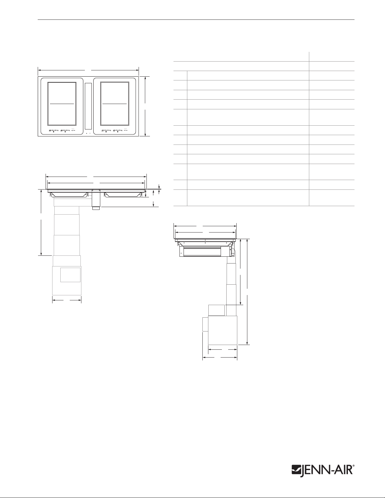
36" INDUCTION DOWNDRAFT COOKTOP WITH ELECTRONIC TOUCH CONTROL
JID4436ES – 36" x 79⁄16" x 2111⁄32"
1 of 8
PRODUCT DIMENSIONS
A
TOP VIEW
A
C
E
MODEL # JID4436ES
in cm
Overall width
A
Overall depth
B
Width of recessed cooktop 349⁄16 87.8
C
Width of blower motor assembly 111⁄8 28.2
B
H
F
G
D
Height from blower housing assembly to
E
countertop (min.-max.)
Height of recessed cooktop 29⁄16 6.5
F
Height from electrical housing to countertop 79⁄16 19.2
G
Height of cooking surface
H
Depth of recessed cooktop 209⁄32 51.5
I
Height from bottom of blower housing
J
assembly to countertop (min.-max.)
Depth of blower housing assembly 111⁄16 28 .1
K
Depth of blower housing assembly with
L
electrical box
36 91.4
2111⁄32 54.2
149⁄16-
211⁄4
5
2913⁄16-
36
37.0
54.0
⁄64 0.2
75.7-
1
92.7
⁄2
137⁄8 35.2
B
I
FRONT VIEW
E
J
D
K
L
SIDE VIEW
IMPORTANT: Dimensional specifications are provided for planning purposes only.
Do not make any cutouts based on this information. Refer to the Installation or Use & Care Guide
before selecting cabinetry, verifying electrical/gas connections, making cutouts or beginning installation.
All Jenn-Air® appliances are appropriately UL, CUL or CSA approved.
8508AdZw316
JENN-AIR® DETAILED PLANNING DIMENSIONS
Side
Cabinet
G
H
Side
Cabinet
E*
G
F
C
e
A
B
B
H
D
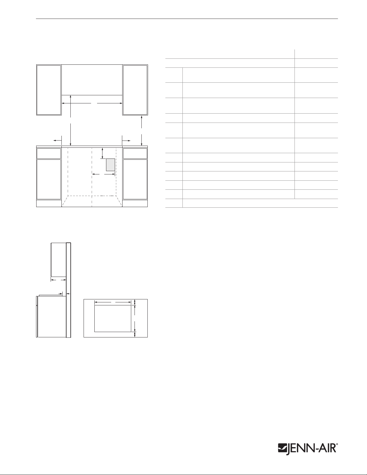
36" INDUCTION DOWNDRAFT COOKTOP WITH ELECTRONIC TOUCH CONTROL
JID4436ES – 36" x 79⁄16" x 2111⁄32"
2 of 8
OPENING/CLEARANCE DIMENSIONS
A
E*
B
D
e
C
FRONT VIEW
Side
Cabinet
G
H
I
MODEL # JID4436ES
in cm
Width of combustible area above cooking
A
surface (min.)
Width from cooktop to fixed wall
B
or other combustible material (min.)
Width to outer edge of outlet from centerline
C
of cabinet (max.)
Height to top edge of outlet (min.)
D
Height to bottom of uncovered wood or
F
B
E*
metal cabinet above cooking surface (min.)
Height to bottom of uncovered wood
F
or metal cabinet (min.)
Depth of upper cabinet (recommended)
G
Depth from cutout to wall (min.)
H
Width of cutout (recommended)
I
Depth of cutout (recommended)
J
Depth from cutout to front of countertop
K
e
Recommended electrical access location
* Dimension can be reduced by 6" (15.2 cm) when bottom of wood or metal cabinet
is covered by not less than 1⁄4" (0.6 cm) flame retardant millboard covered with not
less than No. 28 MSG sheet metal, 0.015" (0.4 mm) stainless steel, 0.024" (0.6 mm)
aluminum or 0.020" (0.5 mm) copper.
36 91.4
21⁄2 6.4
24 61.0
12 30.5
30 76.3
18 45.7
13 33.0
11⁄2 3.8
357⁄16 90.0
207⁄8 53.0
211⁄16 6.8
ELECTRICAL REQUIREMENTS
120/240 volt, 60 Hz, AC only, 40-amp fused, electrical circuit is required. A dedicated
circuit is required.
VENTING REQUIREMENTS
See pages 3-8 for ducting information. This cooktop must be exhausted outdoors
unless using the duct-free filter kit (W10807915). Refer to kit instructions for further
information.
LOCATION REQUIREMENTS
• To ensure cooktop base clearance, cabinet side walls need to be wider than the cutout.
H
J
K
• A minimum clearance of 6" (15.2 cm) is recommended between the side of the
cooktop and side wall for maximum ventilation performance.
• A minimum clearance of 2" (5.1 cm) is recommended between the blower motor
and cabinet for proper cooling. A 6" (15.2 cm) clearance is recommended for
servicing access.
• An under counter built-in oven cannot be installed under this cooktop.
SIDE VIEW
TOP VIEW – CUTOUT
IMPORTANT: Dimensional specifications are provided for planning purposes only.
Do not make any cutouts based on this information. Refer to the Installation or Use & Care Guide
before selecting cabinetry, verifying electrical/gas connections, making cutouts or beginning installation.
All Jenn-Air® appliances are appropriately UL, CUL or CSA approved.
8508AdZw316
JENN-AIR® DETAILED PLANNING DIMENSIONS
F
G
DUCT-FREE KIT
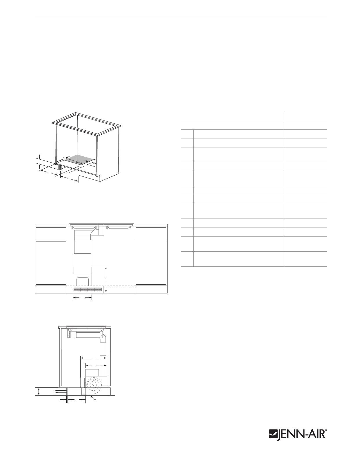
W10807915 – 183⁄8" x 83⁄4" x 4"
DUCT-FREE VENTILATION
The duct-free filter kit (W10807915) is approved for use with induction downdraft cooktop model
JID4436ES. The kit filters the air from the downdraft system and ventilates the conditioned air into
the room through the toe kick or pedestal of the base cabinet. Do not ventilate the air from the
downdraft system into the base cabinet, base cabinet pedestal, crawl space, wall or attic.
OPENING/CLEARANCE DIMENSIONS
MODEL # W10807915
Height of cabinet base cutout 315⁄16 10.0
A
Width of cabinet base cutout 173⁄64 43.3
B
A
E
C
D
B
3/4 TOP VIEW – FRONT KICK PLATE RECIRCULATION
PRODUCT DIMENSIONS
Width from cabinet bottom cutout to
C
centerline of cabinet
Width of cabinet bottom cutout 143⁄4 3 7. 5
D
Depth from front of cabinet bottom
E
cutout to centerline of cabinet
Width of housing 111⁄8 28.2
F
Height of housing 151⁄4 38.7
G
Depth of blower housing assembly with
H
electrical box
Depth of housing 111⁄16 28 .1
I
Minimum height of toe kick 4 10.2
J
Projection from toe kick to face of
K
duct-free cover
Depth from toe kick to blower housing
L
(min.)
3 of 8
in cm
21⁄2 6.4
31⁄2 8.9
137⁄8 35.2
3
⁄4 1.9
81⁄2 21.6
G
FRONT VIEW – FRONT KICK PLATE RECIRCULATION
F
EXHAUST CUTOUT LOCATION
The cutout location in the toe kick area and the cabinet floor is dependent
upon the dimensions of the cooktop and base cabinet.
H
I
Airflow
J
LK
SIDE VIEW – FRONT KICK PLATE RECIRCULATION
IMPORTANT: Dimensional specifications are provided for planning purposes only.
Do not make any cutouts based on this information. Refer to the Installation or Use & Care Guide
before selecting cabinetry, verifying electrical/gas connections, making cutouts or beginning installation.
All Jenn-Air® appliances are appropriately UL, CUL or CSA approved.
Floor
8508AdZw316

JENN-AIR® DETAILED PLANNING DIMENSIONS
H
I
DUCT-FREE KIT
W10807915 – 183⁄8" x 83⁄4" x 4"
DUCT-FREE VENTILATION
The duct-free filter kit (W10807915) is approved for use with induction downdraft cooktop model
JID4436ES. The kit filters the air from the downdraft system and ventilates the conditioned air into
the room through the toe kick or pedestal of the base cabinet. Do not ventilate the air from the
downdraft system into the base cabinet, base cabinet pedestal, crawl space, wall or attic.
OPENING/CLEARANCE DIMENSIONS
MODEL # W10807915
Height of right side cabinet base cutout 315⁄16 10.0
A
Depth of right side cabinet base cutout 173⁄64 43.3
B
E
D
3/4 TOP VIEW – RIGHT SIDE RECIRCULATION
C
F
B
PRODUCT DIMENSIONS
A
Width from cabinet bottom cutout to centerline
C
of cabinet
Width of cabinet bottom cutout 143⁄4 37.5
D
Depth from front of cabinet bottom cutout to
E
centerline of cabinet
Depth from front edge of right side cabinet base
F
cutout to centerline of cabinet
Width of housing 111⁄8 28.2
G
Height of housing 151⁄4 38.7
H
Projection from toe kick to face of duct-free cover
I
Depth from toe kick to blower housing (min.) 81⁄2 21.6
J
Depth of blower housing assembly with
K
electrical box
Depth of housing 111⁄16 28.1
L
4 of 8
in cm
21⁄2 6.4
31⁄2 8.9
61⁄4 15.8
3
⁄4 1.9
137⁄8 35.2
H
I
The cutout location in the base pedestal and the cabinet floor is dependent upon the
dimensions of the cooktop and base cabinet.
G J
EXHAUST CUTOUT LOCATION
FRONT VIEW – RIGHT SIDE RECIRCULATION
K
L
A
Floor
Airflow
B
SIDE VIEW – RIGHT SIDE RECIRCULATION
IMPORTANT: Dimensional specifications are provided for planning purposes only.
Do not make any cutouts based on this information. Refer to the Installation or Use & Care Guide
before selecting cabinetry, verifying electrical/gas connections, making cutouts or beginning installation.
All Jenn-Air® appliances are appropriately UL, CUL or CSA approved.
8508AdZw316

JENN-AIR® DETAILED PLANNING DIMENSIONS
H
DUCT-FREE KIT
W10807915 – 183⁄8" x 83⁄4" x 4"
DUCT-FREE VENTILATION
The duct-free filter kit (W10807915) is approved for use with induction downdraft cooktop model
JID4436ES. The kit filters the air from the downdraft system and ventilates the conditioned air into
the room through the toe kick or pedestal of the base cabinet. Do not ventilate the air from the
downdraft system into the base cabinet, base cabinet pedestal, crawl space, wall or attic.
OPENING/CLEARANCE DIMENSIONS
MODEL # W10807915
Height of left side cabinet base cutout 315⁄16 10.0
A
Depth of left side cabinet base cutout 173⁄64 43.3
B
A
E
C
B
3/4 TOP VIEW – LEFT SIDE RECIRCULATION
F
D
PRODUCT DIMENSIONS
Width from cabinet bottom cutout to centerline
C
of cabinet
Width of cabinet bottom cutout 143⁄4 37.5
D
Depth from front of cabinet bottom cutout to
E
centerline of cabinet
Depth from front edge of left side cabinet base
F
cutout to centerline of cabinet
Width of housing 111⁄8 28.2
G
Height of housing 151⁄4 38.7
H
Projection from toe kick to face of duct-free cover
I
Depth from toe kick to blower housing (min.) 81⁄2 21.6
J
Depth of blower housing assembly with
K
electrical box
Depth of housing 111⁄16 28.1
L
5 of 8
in cm
21⁄2 6.4
31⁄2 8.9
61⁄4 15.8
3
⁄4 1.9
137⁄8 35.2
EXHAUST CUTOUT LOCATION
I
FRONT VIEW – LEFT SIDE RECIRCULATION
GJ
H
The cutout location in the base pedestal and the cabinet floor is dependent upon the
dimensions of the cooktop and base cabinet.
K
L
A
Airflow
Floor
B
SIDE VIEW – LEFT SIDE RECIRCULATION
IMPORTANT: Dimensional specifications are provided for planning purposes only.
Do not make any cutouts based on this information. Refer to the Installation or Use & Care Guide
before selecting cabinetry, verifying electrical/gas connections, making cutouts or beginning installation.
All Jenn-Air® appliances are appropriately UL, CUL or CSA approved.
8508AdZw316

JENN-AIR® DETAILED PLANNING DIMENSIONS
DOWNDRAFT COOKTOP DUCTING ARRANGEMENTS
The diagrams below show typical duct arrangements for downdraft cooktops.The JID4436ES induction downdraft cooktop
also offers a duct-free installation option. For more details, refer to pages 3-5.
OPENING/CLEARANCE DIMENSIONS
in cm
Width of rear cabinet cutout (max.) 17 43.2
A
Height of rear cabinet cutout (min.) 4 10.2
B
A
C
3/4 TOP VIEW – REAR DUCTING
DUCTING CONFIGURATIONS
Roof jack
B
Height from cabinet floor to bottom of cabinet
C
cutout (min.)
1 2.5
DUCTING REQUIREMENTS
COOKTOP DUCT LENGTH DUCT SIZE
10' (3.0 m) or less*
Electric/
Induction
Between 10' (3.0 m) and
60' (18.3 m)
* May be used to vent straight out the back of the cooktop and directly through the wall.
5" (12.7 cm)
diameter*
6" (15.2 cm)
diameter
31⁄4" x 10"
(8.3 cm x 25.4 cm)
6 of 8
(8.3 cm x 25.4 cm) duct –
REAR DUCTING IN WALL TO ROOF
1
⁄4 x 10"
3
54' (16.5 m) max.
CALCULATING MAXIMUM DUCTING LENGTH
• Maximum ducting length is 60' (18.3 m).
• Each 90° elbow equals 5' (1.5 m) duct.
• Use no more than three 90° elbows.
• Flexible metal vent is not recommended.
• Do not install two elbows together.
NOTES:
• For ducting runs up to 30' (9.1 m), install cooktop as shipped.
• For altitudes above 4500' (1372 m), reduce recommended vent run by 20% for
best performance.
• For round duct installations, use transition elbow between blower housing
and ducting.
wall cap
REAR DUCTING THROUGH WALL TO OUTSIDE
IMPORTANT: Dimensional specifications are provided for planning purposes only.
Do not make any cutouts based on this information. Refer to the Installation or Use & Care Guide
before selecting cabinetry, verifying electrical/gas connections, making cutouts or beginning installation.
All Jenn-Air® appliances are appropriately UL, CUL or CSA approved.
8508AdZw316

JENN-AIR® DETAILED PLANNING DIMENSIONS
DOWNDRAFT COOKTOP DUCTING ARRANGEMENTS
The diagrams below show typical duct arrangements for downdraft cooktops.The JID4436ES induction downdraft cooktop
also offers a duct-free installation option. For more details, refer to pages 3-5.
OPENING/CLEARANCE DIMENSIONS
in cm
Depth of cabinet bottom cutout (min.) 11 27.9
A
Width of cabinet bottom cutout (max.) 17 43.2
B
A
7 of 8
B
3/4 TOP VIEW – DUCTING THROUGH
CABINET FLOOR
DUCTING CONFIGURATIONS
wall cap
THROUGH FLOOR BETWEEN JOISTS TO OUTSIDE
31⁄4" x 10" (8.3 x 25.4 cm)
rectangular wall venting
DUCTING REQUIREMENTS
COOKTOP DUCT LENGTH DUCT SIZE
10' (3.0 m) or less*
Electric/
Induction
Between 10' (3.0 m) and
60' (18.3 m)
* May be used to vent straight out the back of the cooktop and directly through the wall.
CALCULATING MAXIMUM DUCTING LENGTH
• Maximum ducting length is 60' (18.3 m).
• Each 90° elbow equals 5' (1.5 m) duct.
• Use no more than three 90° elbows.
• Flexible metal vent is not recommended.
• Do not install two elbows together.
NOTES:
• For ducting runs up to 30' (9.1 m), install cooktop as shipped.
• For altitudes above 4500' (1372 m), reduce recommended vent run by 20% for
best performance.
• For round duct installations, use transition elbow between blower housing
and ducting.
5" (12.7 cm)
diameter*
6" (15.2 cm)
diameter
31⁄4" x 10"
(8.3 cm x 25.4 cm)
wall cap
CONCRETE SLAB INSTALLATION THROUGH WALL
TO OUTSIDE
IMPORTANT: Dimensional specifications are provided for planning purposes only.
Do not make any cutouts based on this information. Refer to the Installation or Use & Care Guide
before selecting cabinetry, verifying electrical/gas connections, making cutouts or beginning installation.
All Jenn-Air® appliances are appropriately UL, CUL or CSA approved.
8508AdZw316

JENN-AIR® DETAILED PLANNING DIMENSIONS
DOWNDRAFT COOKTOP DUCTING ARRANGEMENTS
The diagrams below show typical duct arrangements for downdraft cooktops.The JID4436ES induction downdraft cooktop
also offers a duct-free installation option. For more details, refer to pages 3-5.
DUCTING CONFIGURATIONS
DUCTING REQUIREMENTS
COOKTOP DUCT LENGTH DUCT SIZE
5" (12.7 cm)
diameter*
6" (15.2 cm)
diameter
31⁄4" x 10"
(8.3 cm x 25.4 cm)
wall cap
THROUGH FLOOR BETWEEN JOISTS TO OUTSIDE
wall cap
31⁄4" x 10" (8.3 x 25.4 cm)
rectangular wall venting
10' (3.0 m) or less*
Electric/
Induction
Between 10' (3.0 m) and
60' (18.3 m)
* May be used to vent straight out the back of the cooktop and directly through the wall.
CALCULATING MAXIMUM DUCTING LENGTH
• Maximum ducting length is 60' (18.3 m).
• Each 90° elbow equals 5' (1.5 m) duct.
• Use no more than three 90° elbows.
• Flexible metal vent is not recommended.
• Do not install two elbows together.
NOTES:
• For ducting runs up to 30' (9.1 m), install cooktop as shipped.
• For altitudes above 4500' (1372 m), reduce recommended vent run by 20% for
best performance.
• For round duct installations, use transition elbow between blower housing
and ducting.
8 of 8
CONCRETE SLAB INSTALLATION THROUGH WALL
TO OUTSIDE
IMPORTANT: Dimensional specifications are provided for planning purposes only.
Do not make any cutouts based on this information. Refer to the Installation or Use & Care Guide
before selecting cabinetry, verifying electrical/gas connections, making cutouts or beginning installation.
All Jenn-Air® appliances are appropriately UL, CUL or CSA approved.
8508AdZw316
 Loading...