

Page 1
Technical Information- Dishwasher
JDB4000AWB JDB4000AWQ JDB4000AWS JDB4000AWW
MDB5600AWB MDB5600AWQ MDB5600AWS MDB5600AWW
Due to possibility of personal injury or property damage, always contact an authorized technician for servicing or
repair of this unit. Refer to Service Manual 16021814.
CAUTION
!
All safety information must be followed as provided in Service Manual 16021814.
!
To avoid risk of electrical shock, personal injury, or death, disconnect power to dishwasher before servicing, unless
testing requires power.
Specifications JDB4000AW* MDB5600AW* Benefits JDB4000AW* MDB5600AW*
Power Source
Voltage AC 120 VAC 120 VAC Heavy Wash X X
Amperage (Single Unit) 15 A 15 A Normal Wash X X
Frequency 60 Hz 60 Hz Light Wash X X
Motor horsepower 1/3 1/3 Rinse Only X X
Receptacle N/A N/A Drying System X X
Plug N/A N/A
Dimensions
Height−overall
Width 23 7/8” 23 7/8” *ToughScrub™ X X
Depth 23 1/2” 23 1/2” *Extra Rinse X X
Weight
Un-crated 65 lbs. 65 lbs. Control Lock X X
*On selected models only
33 ½” to 35 ¼” 33 ½” to 35 ¼” 2/4/6 Hour Delay
WARNING
Wash cycles 4 4
Features
QuietSeries 100™ X X
Start
*Sanitizer X X
Automatic Temp
Control
Energy Star X X
Active Vent Dry X X
Finer Filtration X X
Hard Food
Disposer
10 Touch Pad
Controls
X X
X X
X X
X X
May 2004 1 16023063
©2004 Maytag Services
Page 2
Component Specifications
!
WARNING
To avoid risk of electrical shock, personal injury, or death, disconnect power to dishwasher before servicing,
unless testing requires it.
Illustration Component Test Procedure Results
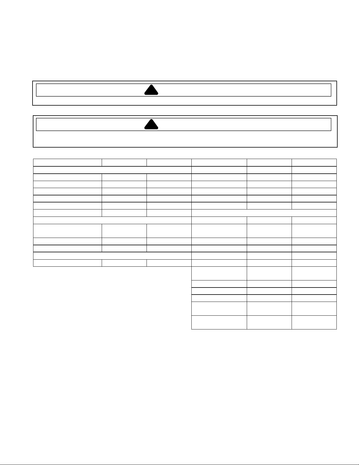
Dishwasher Motor
CCW rotation only
viewed from shaft
end.
1/3HP
120V/60hz, 3.2 amps,
3250 RPM
Main Wattage, 285
watts
Start Wattage, 1115
watts
Control Board See Component Specifications/
Measure resistance from
ST5 (Motor Common – blue) to ST8
(Motor Main - yellow). ..........................
See Component Specifications/Motor
Connections for details.
Membrane Readings for
troubleshooting/pin-out instructions.
3 to 4 Ω
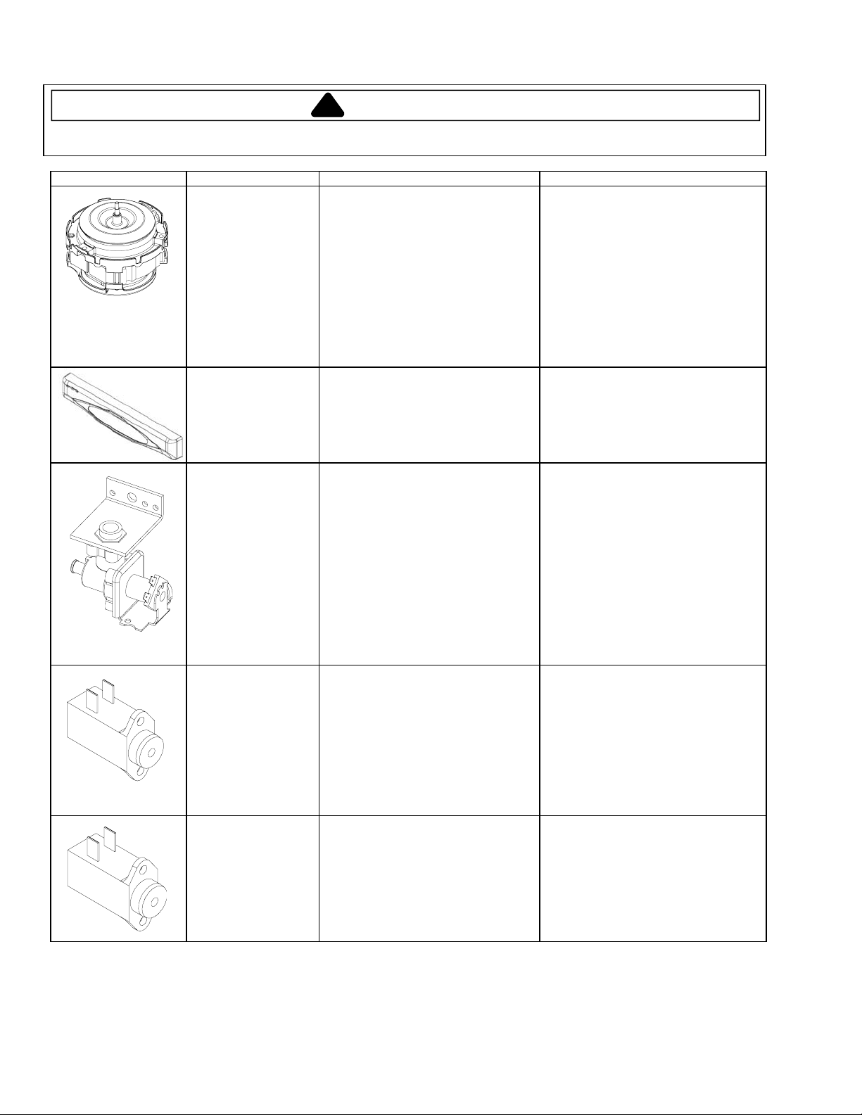
Water valve
120V/60hz, 7 watts
1.13 ± .10 gpm at 20120 psi
Measure resistance from
J6 Pin 4 Aqua (Float switch) to ST4
Black (Common) .................................
1.1 k Ω
(This value assumes the float switch is
closed).
Vent wax motor
120V with 1/4"
actuation stroke
within 60 seconds
Measure resistance from J6 Pin 1
Purple (Vent) to ST4 Black (Common)
1.2 k Ω
Dispenser wax motor
120V with 1/4"
actuation stroke
within 60 seconds
Measure resistance from J6 Pin 3
Tan (Dispenser) to ST4 Black
(Common) ..........................................
2 k Ω
16023063 2 May 2004
©2004 Maytag Services
Page 3
Component Specifications
!
WARNING
To avoid risk of electrical shock, personal injury, or death, disconnect power to dishwasher before servicing,
unless testing requires power.
Illustration Component Test Procedure Results
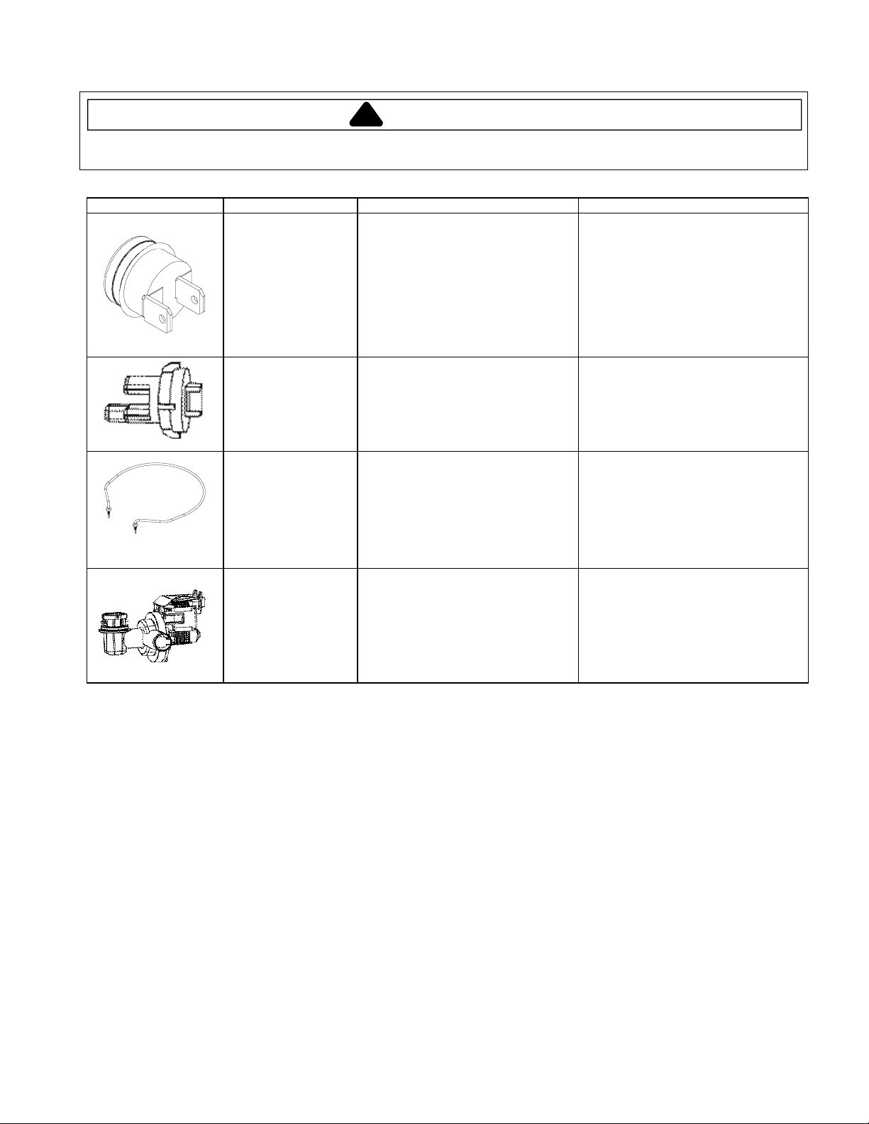
Limit Thermostat
Close on Temperature drop @ 149°F
± 7°F (Temp) ......................................
Open on Temperature drop @ 164°F
± 4°F (Temp) ......................................
0 Ω = Closed
Infinite Ω = Open
Sensor/Thermistor
Heater/Heating
Element
120v/60hz, 650 watts
± 5% in air, 830 watts
± 5% in coldwater
Drain Motor
120v/60hz
10KΩ ± 3% at 77°F and 2.4 k Ω ±
6.5% at 140°F
J5 pin 1 - Orange (Temp) to J5 Pin 4 -
Red (Neutral) .....................................
Measure resistance from ST1
Red/Black (Heater) to ST11 White
(Common) ..........................................
Measure resistance from
ST6 Gray (Drain) to ST4 Black
(Common) ..........................................
See section “Motor Connections and
Diagram” for wiring contacts.
Infinite Ω = Open
0 Ω = Closed
16 Ω
(This value assumes the high limit
thermostat is closed).
25 Ω
May 2004 3 16023063
©2004 Maytag Services
Page 4

Component Readings/Testing
!
WARNING
To avoid risk of electrical shock, personal injury, or death, disconnect power to dishwasher before servicing,
unless testing requires power.
A Manual Function Test may be started by pressing the key
5 times followed by the key within 6 seconds.
The LED wi ll 3 times indicati ng manual test mode is
Normal Wash Flash
active. Specific keypads will turn on or off a component as follows:
When a component is acti vated by pressing a specific keypad, the LED above
the keypad will be . The test will cancel 120 seconds after the last keypad is
press ed. The display (if available) wil l show ‘99’ until the rem aining timeout
period is less than 99 seconds. At this point it will countdown until the mode
times out, is cancelle d, or anothe r key is pressed. To cancel test, pr ess the
Start / Cancel
Press keypad 5 times within 6 seconds. The LEDs will illuminate
in a p rogressive order until all are lit. All LED’s w ill stay on for 1 second then all
go off simultaneously. The display (if available) will begin at ‘50’ and sequence
down to ‘0’ at a 1 second interval and repeat until this mode is terminated. This
mode will repeat.
To cancel, pr ess the keypad .
To check control LEDs, enter . If control fails to
perform as de scribed, replace control. To check control and components, enter
Field Service Test
fault is detected, determine failure as described in the . If a
load component failure has been diagnosed, proceed to the
Test Man ual
Function Test
compon ent as needed.
Note High Current Low Current Motor Error
a wash cycle selected by a consumer. If this happens, the control will go into a
30 second auto restart mode and shut down if the unit is not able to re start the
motor.
keypad.
Extra Rinse
. To check individual load components for proper operation, enter
. Follow test procedure as described. Repair or replace
: The or may be detected during
Manual Function Test
Start
Heavy Wash
Normal Wash
Light Wash
Rinse Only
Sanitize
Heated Dry
On
Wash Motor
Drain Motor
Wat er Val ve
Soap Di spenser (cycle once)
Rinse Aid (cycle twice)
Ven t
Heating Element
Normal Wash
Sales Floor Demo Mode
Start / Cancel
Diagnostic Tips
Sales Floor Demo Mode
. If control fails to perform sequence as described, and a
Field Service Test
Manual Function
Membrane Readings
(Front Only Controls)
Connector
Heavy Wash
Normal Wash
Light Wash
Rinse Only
Auto Clean
Start / Cancel
Delay
Heated Dry
Sanitize
Tough Scrub
Tough Scrub Plus
Extra Rins e
Model ID Jumper
An unpressed switch will read as an open circuit.
A pressed switch will read as 10 k ohms .
* On select models
*
J1
J1
J1
J1
J1
J1
J1
J1
J1
J1
J1
J1
J1
Heater¹
Wash Motor
Drain Motor
Vent Wax Motor
Dispenser Wax Motor
Wat er Val ve ²
Thermi stor
Notes:
1. This value assumes the high l imit thermo stat is closed.
2. This value assumes the float swit ch is closed .
3. Results a re approximate va lues.
Measure Between
Pin 9 - Pin 5
Pin 9 - Pin 6
Pin 9 - Pin 7
Pin 9 - Pin 8
Pin 10 - Pin 5
Pin 10 - Pin 6
Pin 10 - Pin 7
Pin 11 - Pin 5
Pin 11 - Pin 6
Pin 11 - Pin 7
Pin 10 - Pin 8
Pin 11 - Pin 8
Pin 12 - Pin 7
Measure between:
ST1 (Heater) - ST11 (Dlb Neutral)
ST5 (Motor Common) - ST8 (Motor Main)
ST6 (Drain) - ST4 ( Dlb Li ne)
J6 Pin 1 (Vent) - ST4 (Dlb Line)
J6 Pin 3 (Disp) - ST4 (Dlb Line)
J6 Pin 4 (Inlt) - ST4 (Dlb Line)
J5 Pin 1 (Temp) - J5 Pin 4 (Neutral)
Load Readings
A Field Service Test may be started by pr essing the key 5 t imes
followed by the key within 6 seconds. This test must be perf ormed with
clean water to ins ure proper se nsor performance.
“88” will appear in the display (if available*) and the following sequence of
events will occur:
SECONDS
Time frame for Thermistor/Turbidity Sensor check & ca libration may vary
slightly.
The Field Service Test will not repeat. The LED will during
the test mode. Indicator lights (except and the Display) will
illuminate per Sales Floor Demo Mode. If the dishwasher door is opened
during the test, the test sequence will pause, and resume when the door is
closed. To the cancel test, press the keypad.
The con trol h as been desi gned t o test the Sensor Memory and Motor. Dur ing
the Field Service Test, if a fault has been detected, the test will abort any time
after the motor current has been checked and 2 or more LED's will begin to
Flash Memory / Software Check
started. The LED and one of the following:
* On select models
** On units with Front Controls only, this will be the LED on units with
Top & Front Controls, this will be the LED
Auto Clean
Heavy Wash
Normal Wash
Light Wash
Rinse Only
Quick Wash
Heated Dry
Sanitize
Extra Rinse
Tough Scrub Plus
160° Wash
Model ID Jumper
Start / Cancel
Delay
An unpressed switch will read as an open circuit.
A pressed switc h will read as 10 k ohms.
* On select models
Start
106
5
120
180
120
4
. A will occur immediat ely after the test is
(See Note )
See Component I nfo
Field Service Test
FUNCTIONS / ACTIVE LOADS
Vent Wax Motor/Water Valve
Thermi stor check/Turbidi ty Sensor c heck &
calibration - no loads active.
Wash Motor/Vent Wax Motor/Dispenser Wax Motor
Wash Motor/Heater/Vent Wax Motor
Drain Pump
Wat er Val ve
Heavy Wash
Start / Cancel
Heavy Wash
Heavy Wash Flas h
**
Turbidity Sensor Rinse Only
Thermistor Heavy Wash
- high current - LED
Motor Normal Wash
- low current - LED
Motor Light Wash
Memory Failure Heated Dry
- failure - LED
- failure - LED
- LED
Delay
Clean ,
Membrane Readings
(Front & Top Controls)
Measure Between
Pin 10 - Pin 5
Pin 9 - Pin 5
Pin 9 - Pin 6
Pin 9 - Pin 7
Pin 9 - Pin 8
Pin 10 - Pin 6
Pin 11 - Pin 5
Pin 11 - Pin 6
Pin 11 - Pin 8
Pin 10 - Pin 7
Pin 10 - Pin 8
Pin 12 - Pin 8
Pin 9 - Pin 5
Pin 9 - Pin 6
*
Result
16 ohms
3 to 4 ohms
25 ohms
1.2 k ohms
2 k ohms
1.1 k ohms
Connector
J1
J1
J1
J1
J1
J1
J1
J1
J1
J1
J1
J1
J3
J3
16023063 4 May 2004
©2004 Maytag Services
Page 5

Electrical Diagnostics
!
WARNING
To avoid risk of electrical shock, personal injury, or death, disconnect power to dishwasher before servicing,
unless testing requires power.
3
Perform the resistance checks on the component(s) in question at the locations shown on the chart.
*** A resistor in the control board wired in parallel will result in an approximate reading of 4.0 k ohms
with connector J5 plugged in.
due to the additional resistance of the wire harness. Greater variation can occur if the component is
still warm from being energized during testing.
* Select Models Only.
** Nominal value for ohms of electrical resistance of component only. These values will vary slightly
stake lugs 3 & 4, and pin # 8 on connector J5.
2
> With one ohm meter lead connected to the white (neutral) power lead, you should have continuity at
stake lugs 10 & 11.
> With one ohm meter lead connected to the black (line) power lead, you should have continuity at
(A white plastic latch must be inserted in the latch assembly for this test.)
To check continuity from ends of power leads to control board through door switches
1
check components before
Use the "Manual Function Test" [as described on the electrical schematic sheet (6 918139)] to
Pin #12345678 Pin#1234 Stake Lug11109876 54321
OR RD RD AQ PU BK PU TN AQ
opening the door to perform continuity testing or replacing parts.
J5 J6
connector unplugged)***
2.4K* +/- 6.5% @ 140
10K* +/- 3% @ 77
o
F
o
F
*Vent WM
(1.2K**)
Resistance Check Points and Values
Thermistor (thru harness only with
Disp. WM
(2K**)
Circuit Board
must be closed)
Water Valve
(float switch
(1.1K**)
WH WH
before performing any resistance or
Always
YL GY BU BK BK RD
Drain Motor
(25**)
be closed)
(High limit t'stat must
(14.5 - 16.5**)
Heater
Wash Motor
(3 - 4**)
continuity checks.
remove power to the unit
BK
May 2004 5 16023063
©2004 Maytag Services
Page 6

Motor Connectivity
!
To avoid risk of electrical shock, personal injury, or death, disconnect power to dishwasher before servicing,
unless testing requires power.
WARNING
Wire harness
Connection plug
Blue (Co mmo n)
Yellow
(Main)
Green
(Gro und)
(Start)
Red
1/3HP
120V/60hz, 3.2 amps, 3250 RPM
16023063 6 May 2004
©2004 Maytag Services
Page 7

Wiring Diagram
g
!
WARNING
To avoid risk of electrical shock, personal injury, or death, disconnect power to dishwasher before servicing,
unless testing requires power.
BK
DOOR SWITCH
(LI)
BK
BK
LI
WH
N
WH
DOOR SWITCH
(N)
KEY
WIRES NOT CONNECTED
WIRES CONNECTED
BK
WH
WH
RD
BK
THERMOSTAT
RD
BK
WH
RD
BK
RD
BK
HEATER
BK BU
RD
BK
RD
BK
BK
BK
BU YL
BK
YL
BK
BK
YLBU RD
MAIN
OVERLOAD
WASH MO TOR
GY
GY
MOTOR
CAPACITOR
GR
START
GROUND
NOTE: SOME WIRES HAVE
STRIPES. STRIPED WIRES ARE
LABELED WITH THE SOLID
COLOR FIR ST AND THE ST RIPE
COLOR SECOND.
YL
WH
YL
GR
GR
(TERMINA L
BOX)
(TUB SHIE LD)
RD
WH
RD
GR
CIRCUIT BOARD
WH
WH AQ
WH
WH
AQ
GY
AQ
GY
BK
DRAIN
MOTOR
RD
GR
(HINGE)
RD
EXAMPLE: A RED WIRE WITH A
BLACK STRIPE WOULD BE
LABELED
TN
TN
FLOAT
SWITCH
BK
J6
TN
AQ
BK
WATER
VALVE
PU
PIN
1
PU
AQ
PU
BK
TN
PU
VENT
BK
TN
DISPENSER
J5
PU
BK
AQ
PU
AQ
PU
BK
BK
BK
BK
BK
BK
PIN
1
OR
RD
RDAQ
RD
RD
OR PU RDAQ
SENSOR & THERMIST OR
OR
BK
COLOR CODE
AQ AQUA
BK B LACK
BU BLUE
BR BROWN
GY G RAY
GN GRE EN
OR ORA NGE
PK P INK
PU PURPLE
RD RED
TN TAN
WH WHITE
YL YELLOW
OR
AQ
PU
BK
OR
RD
OR
BK
Component Information
120V / 60hz, 3.2 amps, 3250 RPM
Main wattage, 285 watts
Start wattage, 1115 watts
1.13 ± .1 0 gpm at 20 - 120 psi
Element 120V / 60hz, 650 wat ts ± 5% in air
830 watts ± 5% in cold water
Close at 149° ± 7°F (6 5.0° ± 3.9°C)
Open at 164° ± 4° F (73. 3° ± 2.3 °C)
10k ohms ± 3% at 77°F (25°C) and
2.4k ohms ± 6.5% at 140°F (60°C)
actuation stroke within 90 seconds
Detergent & Ri nse Aid - 120V
incremental duty with ¼” actuation
stroke within 90 seconds
185°F(85°C), 15µf + 10% / -5%
These part s are present o n
models with 3 racks.
Wash Motor 1/3 HP motor,
Water Valve 120V / 60hz, 7 watt s
Heatin
Limit Thermostat SPST ¼” terminal switch
Thermistor Resistance and tol erance :
Wax Motors Vent - 12 0V continuous duty ¼”
Capacitor 300V / 50 - 60hz
Drain Motor 45 watts
May 2004 7 16023063
©2004 Maytag Services
Page 8

Cycle Chart
!
WARNING
To avoid risk of electrical shock, personal injury, or death, disconnect power to dishwasher before servicing,
unless testing requires power.
Notes
1. All times are approx imate.
2. Temperature checks force a maximum 20 minu te heating dela y to reach th e desired tempera ture.
3. The cycle definition gives the minimum and maximum possible cycle lengths. Actual cycle length and executed cycle functions will vary based on the sensor input.
4. Fill l ength var ies betwe en differ ent models .
Auto Clean
Temperature Options (Available on select models)
Sanitize Sanitize
160° Wash 160° Wash
: If the option is available for a given cycle, it forces a 160°F temp check prior to the rinse aid dispense in the final rinse.
Available Options:
Extra Rinse
Tough Scrub
Tough Scrub Pl us Tough Scrub
: If the o ption is available for a given cycle, it forces a temp check at the end of the main wash, a 154°F temp check prior to the rinse aid dispense in the final rinse and adds an additional 5 minutes of rinse before the rinse aid dispense.
- This option overrides the sensor’s decision to skip cycle functions.
- This option is the same as but the main wash temp check is boosted to 145°F.
AUTO CLEAN CYCLE
(131 Minutes - max)
(97 Minutes - min)
- This option adds an additional fill between the main wash and the fi nal rinse for an additional 5 minutes of unheated rinse.
1:46 max
1:36 min
FILL
WASH
PRE
8:00
DRAIN
2:20
SKIP? SKIP? SKIP? SKIP?
1.46 max
1:36 min
DISP
DET
HEATED
WASH
26:00
WASH
2:00
CHECK
TEMP
140°F
DRAIN
2:00
1:46 max
1:36 min
RINSE
10:00
PRE
DRAIN
2:00
1:46 max
1:36 min
FILL
RINSE
10:00
PRE
DRAIN
2:00
1:46 max
1:36 min
RINSE
10:00
HEATED
RINSE
10:00
Available Options:
Extra Rinse
Tough Scrub
Tough Scrub Pl us Tough Scrub
- This option is the same as but the main wash temp check is boosted to 145°F.
HEATED
FILL
HEATED
FILL
HEATED
HEATED
FILL
HEATED
HEAVY WASH CYCLE
(131 minutes - max)
(130 Minutes - min)
- This option adds an additional fill between the main wash and the fi nal rinse for an additional 10 minutes of heated rinse.
- This option adds and additional 5 minutes of heated wash to the pre-wash, an additio nal 12 minutes of heated wash to the main wash and an additional 5 minutes of heated rinse to the second pre-rinse.
1:46 max
1:36 min
FILL
WASH
PRE
8:00
DRAIN
2:20
1:46 max
1:36 min
FILL
HEATED
WASH
10:00
DISP
DET
HEATED
WASH
18:00
CHECK
TEMP
140°F
DRAIN
2:00
1:46 max
1:36 min
FILL
RINSE
10:00
PRE
DRAIN
2:00
1:46 max
1:36 min
FILL
RINSE
10:00
PRE
DRAIN
2:00
1:46 max
1:36 min
FILL
HEATED
RINSE
20:00
CHECK
TEMP
145°F
Available Options:
Extra Rinse
Tough Scrub
Tough Scrub Pl us Tough Scrub
- This option is the same as but the main wash temp check is boosted to 145°F.
HEATED
If sensor detects heavier soil, the temp check wi ll be 145 ° F
HEATED
NORMAL WASH CYCLE
(118 Minutes - max)
(97 Minutes - min)
- This option adds an additional fill between the main wash and the fi nal rinse for an additional 5 minutes of unheated rinse.
- This option overrides the sensor’s decision to skip cycle functions and a dds an additional 7 minutes of heated wash to the main wash.
1:46 max
1:36 min
FILL
WASH
PRE
8:00
DRAIN
2:20
SKIP? SKIP? SKIP? SKIP?
1:46 max
1:36 min
DISP
DET
HEATED
WASH
26:00
WASH
2:00
SEE NOTE
CHECK
TC 1
DRAIN
2:00
1:46 max
1:36 min
FILL
RINSE
10:00
PRE
DRAIN
TC 1: If sensor detects lighter soil, the temp check will be 128 ° F
TC 2: If sensor detects lighter soil, the temp check will be 140 ° F
2:00
If sensor detects heavier soil, the temp check will be 140 ° F
1:46 max
1:36 min
RINSE
10:00
HEATED
RINSE
10:00
SEE NOTE
CHECK
TC 2
RINSE
DISP
AID
RINSE
5:00
Available Options:
Extra Rinse
Tough Scrub
Tough Scrub Pl us Tough Scrub
- This option adds and additional 18 minutes of heated wash to the main wash and 5 minutes o f heated rinse to the final rinse.
- This option is the same as but the main wash temp check is boosted to 145°F.
HEATED
FILL
HEATED
TEMP
HEATED
FILL
HEATED
TEMP
LIGHT WASH CYCLE
82 Minu tes
- This option adds an additional fill between the main wash and the fi nal rinse for an additional 5 minutes of unheated rinse.
1:46 max
1:36 min
FILL
WASH
10:00
PRE
DRAIN
2:20
1:46 max
1:36 min
FILL
DISP
DET
HEATED
WASH
10:00
DRAIN
2:00
1:46 max
1:36 min
FILL
HEATED
RINSE
15:00
CHECK
TEMP
140°F
RINSE
DISP
AID
RINSE
5:00
DRAIN
2:00
FILL
0:02
CYCLE
30:00
DRY
Available Options:
Extra Rinse
QUICK WASH CYCLE
38 Minu tes
- This options adds an additional fill between the main w ash and the final rinse for an additional 5 minutes of unheated rinse.
1:46 max
1:36 min
FILL
HEATED
dry cycle.
DISP
DET
HEATED
WASH
10:00
DRAIN
2:00
1:46 max
1:36 min
FILL
HEATED
Rinse
15:00
RINSE
DISP
AID
RINSE
5:00
DRAIN
2:00
FILL
0:02
Notes: If is not selected, the heater will not be act ivated during the dry cycle.
HEATER
3:00or1:00
ON
If is selected, the first two minutes of heating is changed to 2 minutes of unheated at the end of the
Heated Dry
160° Wash
HEATER
OFF
3:00
HEATER
1:00
ON
HEATER
OFF
3:00
HEATER
1:00
ON
HEATER
OFF
3:00
Available Options:
No options are available with the cycle.
RINSE ONLY CYCLE
9 Minutes
Rinse Only
1:46 max
1:36 min
FILL
RINSE
5:00
DRAIN
2:00
FILL
0:02
DRY CYCLE 160° Wash
HEATER
3:00
ON
HEATER
VENT CLOSED VENT OPENED
OFF
1:30
(Models without option)
HEATER
1:00
ON
HEATER
OFF
1:30
DRY CYCLE 160° Wash
Note: If is not selected, the heater will not be activated during the dry cycle.
HEATER
1:00
VENT CLOSED VENT OPENED
ON
Heated Dry
HEATER
OFF
1:30
(Models with option)
HEATER
1:00
ON
HEATER
OFF
1:30
HEATER
1:00
ON
HEATER
OFF
1:30
CHECK
TEMP
145°F
This represents t he porti on of a cycl e that be
omitted. The determination of whether a segment
is skipped or not is made by input from the sensor.
SKIP?
MAY
RINSE
DISP
AID
RINSE
5:00
DRAIN
2:00
FILL
0:02
CYCLE
30:00
DRY
RINSE
DISP
AID
RINSE
5:00
DRAIN
2:00
FILL
0:02
CYCLE
30:00
DRY
DRAIN
2:00
FILL
0:02
CYCLE
30:00
DRY
1:00
3:00
1:00
3:00
1:00
HEATER
ON
HEATER
OFF
HEATER
ON
HEATER
OFF
HEATER
ON
HEATER
OFF
7:00or9:00
1:00
1:30
1:00
1:30
1:00
9:30
HEATER
ON
HEATER
OFF
HEATER
ON
HEATER
OFF
HEATER
ON
HEATER
OFF
16023063 8 May 2004
©2004 Maytag Services
 Loading...