

Page 1

Service
This manual is to be used by qualified appliance
technicians only. Maytag does not assume any
responsibility for property damage or personal
injury for improper service procedures done by
an unqualified person.
Jet Clean II
Stainless Steel
Dishwashers
This Base Manual covers general information
Refer to individual Technical Sheet
for information on specific models
This manual includes, but is
not limited to the following:
Maytag
MDB8750AW
MDB9750AW
Jenn-Air
JDB1060AW
JDB1100AW
JDB2100AW
JDB2150AWP
16022783
January 2004
Page 2
Important Information
Important Notices for Servicers and Consumers
Maytag will not be responsible for personal injury or property damage from improper service procedures. Pride and
workmanship go into every product to provide our customers with quality products. It is possible, however , that
during its lifetime a product may require service. Products should be serviced only by a qualified service technician
who is familiar with the safety procedures required in the repair and who is equipped with the proper tools, parts,
testing instruments and the appropriate service information. IT IS THE TECHNICIANS RESPONSIBLITY TO
REVIEW ALL APPROPRIATE SERVICE INFORMATION BEFORE BEGINNING REPAIRS.
!
To avoid risk of severe personal injury or death, disconnect power before working/servicing on appliance to avoid
electrical shock.
To locate an authorized servicer, please consult your telephone book or the dealer from whom you purchased this
product. For further assistance, please contact:
Customer Service Support Center
CAIR Center
Web Site Telephone Number
WWW.AMANA.COM ............................................... 1-800-843-0304
WWW.JENNAIR.COM ............................................ 1-800-536-6247
WWW.MAYTAG.COM............................................. 1-800-688-9900
CAIR Center in Canada.......................................... 1-800-688-2002
Amana Canada Product .......................................... 1-866-587-2002
WARNING
Recognize Safety Symbols, Words, and Labels
DANGER
!
DANGER—Immediate hazards which WILL result in severe personal injury or death.
WARNING
!
WARNING—Hazards or unsafe practices which COULD result in severe personal injury or death.
!
CAUTION
CAUTION—Hazards or unsafe practices which COULD result in minor personal injury, product or property
damage.
2 16022783 Rev . 0 ©2004 Maytag Appliances Company
Page 3

Table of Contents
Important Information
Important Notices for Consumers and Servicers.... 2
Recognize Safety Symbols, Words, and Labels ... 2
Important Safety Information
General Information...............................................4
Related Publications.............................................4
General Precautions and Warnings.......................4
Product Warning Labels
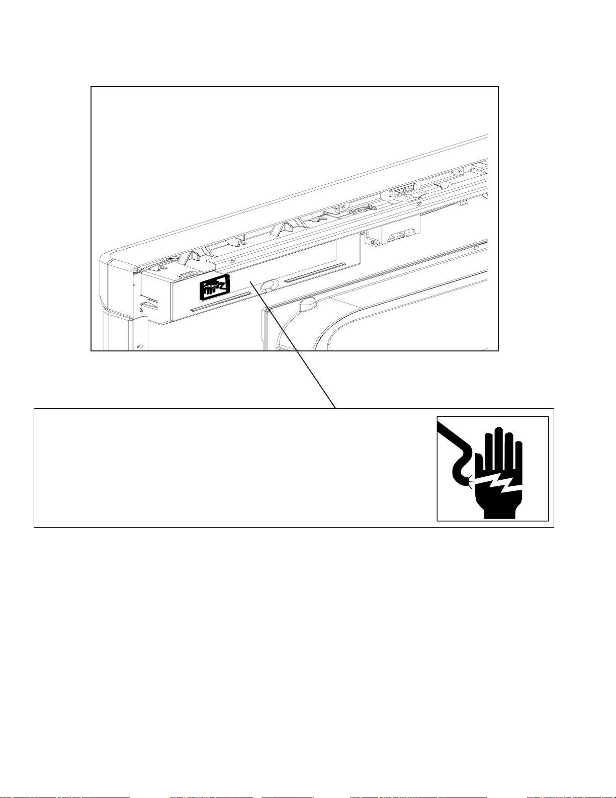
Junction Box Warning...........................................5
Support Panel Warning.........................................5
Control Cover Warning ..........................................6
Electrical Equipment & Testing
Electrical T est Equipment .....................................7
Appliance T est Meter ............................................7
Continuity T esting .................................................7
Digital T est Meter..................................................7
Volt age Checks ..............................................8
Motor T est Cord ....................................................8
Grounding Polarity ................................................8
Electrical Tests
Water V alve ..........................................................9
Detergent / Rinse Aid Disp Wax Mtr Check ..........9
Cycles & Options
Cycles ................................................................10
Options............................................................... 11
Display ............................................................... 12
Control Style by Model........................................ 13
Troubleshooting
Will Not Fill......................................................... 15
Overflows ............................................................15
Poor Water Circulation........................................ 15
Poor Washability ................................................ 16
Will Not Drain ..................................................... 16
Continues to Drain ..............................................16
Poor Drying ........................................................ 16
Water Leaks .......................................................17
Noise ..................................................................17
Will Not Start or Program.................................... 17
Will Not Fill......................................................... 17
Will Not Wash .................................................... 18
Will Not Drain ..................................................... 18
Will Not Dry ........................................................18
Manual Function T est ......................................... 18
Field Service T est ............................................... 18
Troubleshooting Flow Chart
Installation Issues............................................... 19
Leak Issues Page 1 ............................................20
Leak Issues Page 2 ............................................21
No Function Operation Issues Page 1.................22
No Function Operation Issues Page 2.................23
Wash Performance / S taining Issues Page 1 ......24
Wash Performance / S taining Issues Page 2 ......25
Dry Performance Page 1..................................... 26
Dry Performance Page 2..................................... 27
Noise Issues Page 1...........................................28
Noise Issues Page 2...........................................29
Service and Disassembly Procedures
Front Support and T oe Panel Removal ................ 30
Inner Door Panel Removal ................................... 31
Detergent / Rinse Aid Disp..................................31
Wax Motor Detergent / Rinse Aid Disp................ 32
Vent....................................................................32
Wire Cover ..........................................................32
Door Latch & Switch Holder Assembly................ 3 3
PC Boar d............................................................ 3 4
T echnical Sheet ..................................................34
Control Panel ......................................................34
Door Latch Strike................................................ 34
Door Gasket ....................................................... 35
Outer Door.......................................................... 35
Door Hinge And Support ..................................... 36
Door Spring......................................................... 36
Door Spring And Component Replacement..........37
Over Pressure Filter ............................................37
T op W ash Arm.................................................... 3 7
Manifold ..............................................................38
Docking Station ..................................................38
Lower Wash Arm ................................................ 38
Float ...................................................................39
Heating Element .................................................40
Thermostats ....................................................... 41
Water V alve ........................................................ 41
Air Water Inlet and V ent......................................42
Upper Rack Removal ..........................................43
Tub Wheels ........................................................ 43
Turbidity Sensor..................................................43
Drain Pump ........................................................ 44
Wash Motor Assembly ....................................... 45
Appendix A
Installation Instructions ....................................... A-2
©2004 Maytag Appliances Company 16022783 Rev. 0 3
Page 4
Important Safety Information
WARNING
!
To avoid personal injury or death from improper
servicing, make sure you read and understand the
descriptions and meaning of various safety symbols,
words and labels used in this manual, before
attempting any procedures described in the manual.
Failure to understand and comply with safety
information may result in severe personal injury or
death.
General Information
This Service Manual describes the operation,
disassembly , troubleshooting, and repair of Maytag
Dishwashers. It is intended for use by authorized
servicer’s who troubleshoot and repair these units.
NOTE: It is assumed that users of this manual are
familiar with the use of tools and equipment used
to troubleshoot and repair electrical, and
mechanical systems; and understand the
terminology used to describe and discuss them.
®
Related Publications
This is a base service manual, covering a range of
similar models. It is intended to be used in conjunction
with the Parts Manual and Technical Sheet covering
specific model being serviced.
General Precautions and Warnings
• Dispose of discarded appliance and shipping or
packing material properly .
• Do not allow children to play in or on dishwasher.
• Do not abuse, sit, stand or play on door or racks of a
dishwasher.
• Use only detergents and rinse agents recommended for
use in a dishwasher.
• Store dishwasher detergent and rinse agents out of the
reach of children.
• If the dishwasher drains into a food disposer, make
sure disposer is completely empty before running
dishwasher.
• Repairs should be done by a qualified technician.
• Do not tamper with controls.
• Do not touch the heating element during or immediately
after use.
• Load sharp knives with the handles up to reduce the
risk of cut-type injuries or damaging seal.
4 16022783 Rev. 0 ©2004 Maytag Appliances Company
To avoid risk of personal injury or death due to
electrical shock:
• Grounding wires and wires colored like grounding
wires are NOT to be used as current carrying
conductors.
• Standard accepted color coding for ground wires
is green or green with a yellow stripe.
• Grounding wires should not be removed from
individual components while servicing, unless
component is to be removed and replaced.
• Replace all removed grounding wires before
completing service.
To avoid death, severe personal injury, fire or
electrical shock when using dishwasher observe
the following:
• Observe all local codes and ordinances.
• Disconnect electrical power to dishwasher before
servicing.
• Connect dishwasher to a grounded metal,
permanent wiring system.
• DO NOT ground to gas line.
• DO NOT ground to cold water pipe if pipe is
interrupted by plastic, non-metallic gaskets, or
other insulating (non-conducting) materials.
• Check with a qualified electrician if you are not
sure this appliance is properly grounded.
• This dishwasher is designed to operate on
regular house current (120 V , 60 Hz). Use a
circuit equipped with a 15 ampere fuse or circuit
breaker. Use a 20 ampere fuse if dishwasher is
connected with a food waste disposer.
• Under certain conditions, hydrogen gas may be
produced in a hot water system that has not
been used for 2 weeks or more. HYDROGEN
GAS IS EXPLOSIVE. If hot water system has
not been used for such a period, before using
dishwasher, turn on all hot water faucet s and let
water flow from each for several minutes. This will
release any accumulated hydrogen gas.
HYDROGEN GAS IS FLAMMABLE. Do not
smoke or use an open flame during this time.
• Do not store or use combustible materials,
gasoline or other flammable vapors and liquids in
the vicinity of this or any other appliance.
• Do not wash plastic items unless marked
"dishwasher safe" or the equivalent. If not
marked, check with manufacturer for
recommendations. Items that are not dishwasher
safe may melt and create a potential fire hazard.
• To avoid entrapment and/or suffocation, remove
door or door latch mechanism from any
dishwasher that is discarded or not in use.
WARNING
!
WARNING
!
Page 5
Important Safety Information
PRECAUCIÓN:
Desconecte la
energía eléctrica
antes de darie
servicio.
ATENCIÓN:
Solamente use
conductores de
cobre. Use cables de
suministro adecuados
para 75° (167°F).
CAUTION:
Disconnect electr ical powe r
before servicing.
ATTENTION:
Use copper conductors only.
Use supply wires suitable for 75°C ( 167°F).
ATTENTION:
Débrancher de
l'alimentation électrique avant tout dépannage.
ATTENTION:
Utiliser des co nducteurs en
cuivre uniquement. Utiliser des fils
d'alimentatio n pouv an t su pporter une
température de 75°C (167°F).
GROUNDING: This unit must
be grounded in accordance with local
and/or national electric codes.
WARNING: The heating
element, drain pump, harness clip,
dispenser mount, and water valve are
intentionally not grounded an d may
present a risk of electrical shock on ly
during servicing. Discharge motor
capacitior before servicing. Failure to
follow these instructions can result in
death, serious injury, fire, or electrical
shock.
MISE Á LA TERRE:
doit être re lié à la terre conformément aux
codes élec triques locaux et/ou nationaux.
AVERTISSEMENT: La résistance,
la pompe de vidange, l'atta ch e du hamais, l a
mont ur e de distributeur et l'éle ct r o v a nn e ne
sont pas reliés à la terre intentionnellement et
peuvent présenter des risques d'électrocution
uniquement en cas d'intervention de service
aprés-vente. Décharger le condensateur
avant toute intervention. Le non-respect de
ces consignes peut entrainer la mort, des
blessures graves, l'incendie ou l'électrocution.
Cet appareil
CONEXI ÓN A TIERRA:
unidad debe estar conectada a tierra de
acuerdo con los códigos eléctricos locales y
nacionales.
ADVERTENCIA: El elemento calentador,
la bomba de drenado, el sujetador del arnés,
el montaje del surtidor y la válvula de
agua están sin conectar a tierra
intencionalmente podrían presentar un riesgo
de desca r gas e léc t ric as cu ando se les da
servicio s olame nte. El no seguir estas
instrucciones podría causar la muerte, lesiones
graves, incendios o descargas eléctricas.
Esta
©2004 Maytag Appliances Company 16022783 Rev. 0 5
Page 6
Important Safety Information
l
e
c
t
r
o
n
i
q
e
u
c
e
e
e
s
s
s
c
t
o
d
n
e
s
l
i
g
a
c
n
t
r
e
ó
s
n
i
c
o
e
t
s
r
u
t
á
c
c
i
o
l
n
t
p
e
a
o
s
l
d
l
r
t
í
a
i
m
n
e
s
u
n
t
s
i
l
c
o
n
n
e
c
t
e
d
.
p
e
u
c
t
o
e
m
n
m
t
r
c
a
a
o
n
î
n
n
d
e
s
e
r
t
A
a
p
l
a
m
V
e
m
u
m
E
p
v
o
R
e
e
o
r
n
d
n
t
T
,
t
r
t
d
í
I
s
r
S
e
p
e
c
o
s
e
s
a
S
u
t
r
u
s
e
e
m
b
E
s
n
t
r
l
e
D
s
é
s
b
u
r
s
r
a
e
t
n
s
e
c
n
g
h
s
r
e
i
a
o
o
r
v
n
i
a
e
n
v
u
s
s
a
n
,
e
q
n
e
l
'
s
u
i
t
n
c
e
f
t
o
o
c
o
e
s
l
i
n
u
s
'
a
n
e
t
g
e
p
l
'
d
c
a
r
p
t
a
i
i
p
e
e
n
a
e
v
p
t
r
o
e
l
e
e
a
a
d
u
s
r
i
v
r
l
e
,
e
e
l
e
n
s
'
i
n
i
n
q
n
e
l
c
é
e
d
c
u
o
t
l
c
r
s
e
e
i
e
é
g
o
n
t
o
c
n
b
í
n
p
e
s
i
t
d
t
r
r
a
.
o
c
e
a
o
i
d
t
n
L
o
w
n
a
c
t
a
d
s
é
c
r
u
e
e
e
b
h
l
t
r
s
c
o
s
a
i
r
o
a
é
o
b
c
d
d
a
m
.
e
n
e
o
n
e
e
n
L
.
n
f
n
c
m
a
n
d
e
-
r
é
e
s
p
e
d
c
e
t
n
d
s
a
c
t
o
e
n
u
t
r
r
o
l
e
l
e
r
e
s
t
a
s
d
e
i
e
n
e
l
s
r
c
g
o
i
z
n
e
t
r
d
o
a
c
a
l
s
h
o
o
w
c
e
k
r
.
i
s
d
i
s
o
h
e
e
d
r
e
c
r
e
s
é
r
a
e
c
n
a
g
s
.
r
o
t
r
a
o
í
s
l
u
L
e
g
n
a
n
e
l
e
t
a
l
s
e
r
a
c
i
s
s
v
e
n
l
o
i
e
é
e
r
c
c
n
c
v
d
i
n
o
l
t
é
t
n
i
e
c
r
e
n
r
c
g
o
a
i
r
i
g
c
t
o
.
l
t
h
a
r
m
í
i
.
E
a
c
,
.
E
l
a
a
.
s
E
e
s
l
y
L
e
l
c
.
o
t
r
r
n
r
i
e
o
s
o
o
m
u
c
n
s
s
a
i
e
c
a
p
i
i
g
n
c
n
a
u
o
j
u
c
a
i
n
r
i
c
t
t
y
t
o
r
i
,
o
v
r
f
e
e
l
i
r
i
s
e
s
a
,
f
t
o
e
r
r
e
e
l
l
e
e
c
c
t
t
r
r
i
i
c
a
l
p
a
M
a
e
e
s
n
r
n
o
u
i
o
n
à
:
m
D
s
i
o
n
e
u
é
s
d
h
a
c
s
o
t
n
a
n
e
t
i
o
n
s
a
c
c
i
t
o
r
r
E
e
l
g
s
a
A
c
i
N
z
e
m
D
a
r
T
u
d
V
F
a
o
e
E
a
c
r
t
t
t
R
o
i
i
l
e
u
v
d
,
r
o
T
p
o
e
l
s
e
E
o
d
e
t
w
o
N
l
e
e
t
f
s
C
i
W
o
r
e
p
l
i
m
I
l
A
s
o
A
p
w
d
R
:
o
i
D
s
t
N
i
h
s
c
e
o
I
N
s
n
e
n
G
e
i
n
:
c
t
t
r
e
u
d
c
.
C
a
p
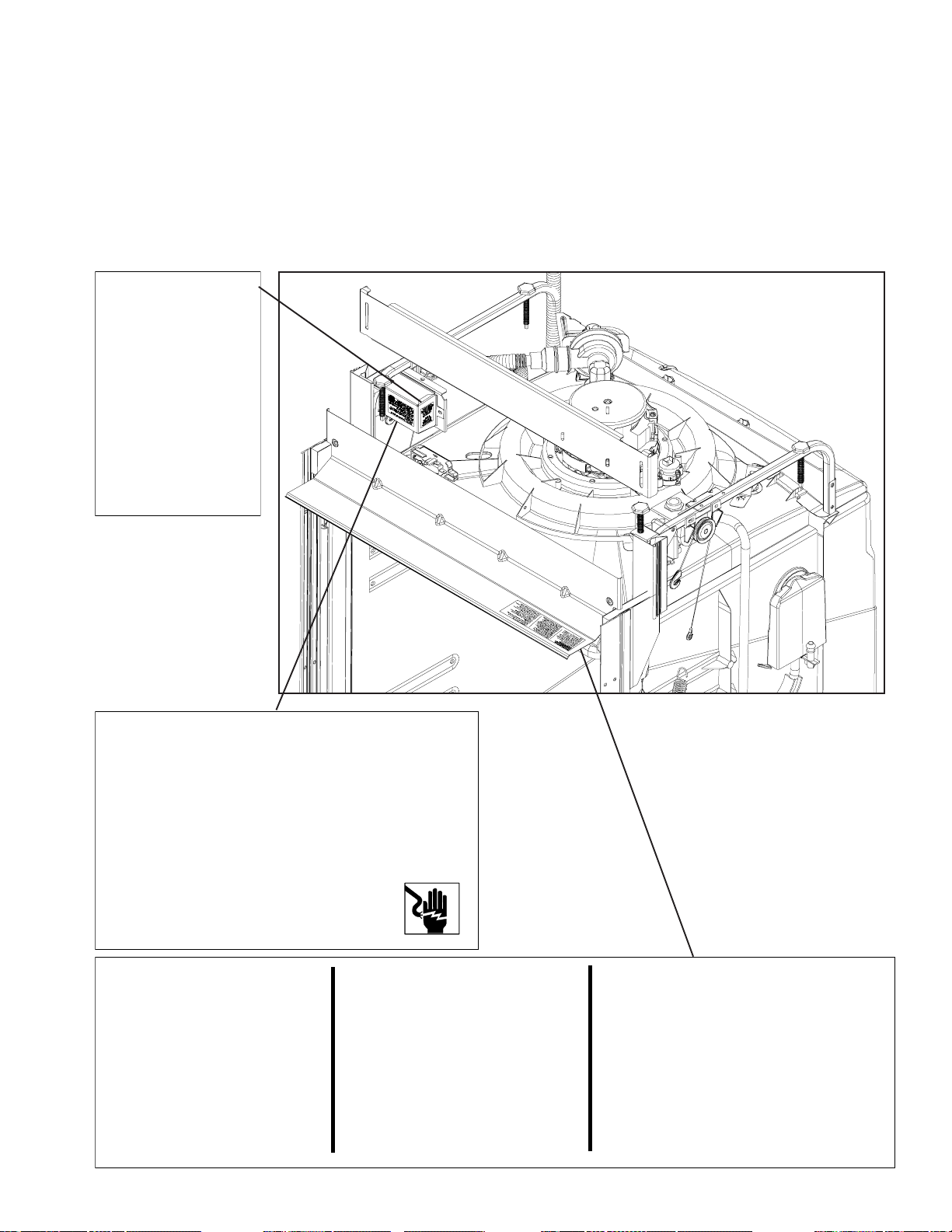
WARNING: Disconnect power before servicing. Electronic control is energized at all times until
power is disconnected. Capacitors on control may remain active after electrical power is disconnected.
Failure to follow these instructions can result in death, serious injury, fire, or electrical shock.
ADVERTENCIA: Desconecte la energí antes de darle servicio. El control electrónico está
energizado todo el tiempo hasta que se desconecta la energía. Los capacitores del control podrían
permanecer activos después de desconectar la energía eléctrica. El no seguir estas instrucciones
podrí causar la muerte, lesiones graves, incendios o descargas eléctricas.
AVERTISSEMENT: Débrancher avant toute intervention. La commande électronique est
constamment sous tension à moins que l'appareil ne soit débranché. Les condensateurs de la
commande peuvent rester sous tension une fois l'appareil débranché. Le non-respect de ces consignes
peut entraîner la mort, des blessures graves, l'incendie ou l' électrocution.
6 16022783 Rev. 0 ©2004 Maytag Appliances Company
Page 7
Electrical Equipment & Testing
Electrical T est Equipment
The equipment required to service these models depends
largely upon the condition encountered. Locating a
malfunction will often require the use of electrical testing
equipment such as:
Appliance T est Meter
Clamp-On Ammeter
Motor T est Cord
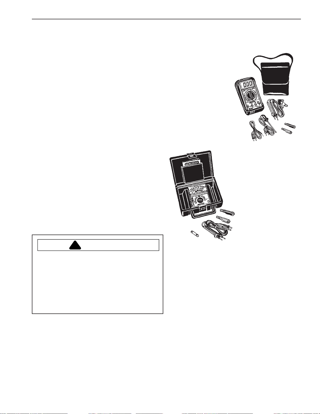
Appliance T est Meter
An Appliance Test Meter is a multi-purpose tester
combining an AC/DC volt age tester with a multi-range
ohmmeter.
The easiest means of testing electrical components is
"Continuity Testing" with an appliance meter. Continuity
is a complete or continuous path from one point in an
electrical circuit to another.
Digital Test Meter
can be used to check for open
or closed circuits, measure
resistance, AC and DC volts,
and temperature.
Analog T est Meter
can be used to check for
open or closed circuits,
measure resistance, AC and
DC volts, and temperature.
The obvious advantages of being able to check electrical
components and circuits without power applied is one of
the features of the Ohmmeter. Multiple ranges allow
accurate determination of resistances of both single
components and entire circuit paths. Resistance is
measured in "Ohms."
WARNING
!
T o avoid risk of personal injury or death due to
electrical shock:
Always be sure the power has been disconnected
before making resistance measurements. Failure to
do so will also result in damage to your meter!
Internal batteries provide all the power needed to
make resistance checks. They should be checked
at least once a year and replaced as needed.
Continuity T esting: is a process of eliminating electrical
components involved in a given function of the appliance,
until the inoperative part is found. By reviewing the list of
possible electrical problems under a given condition, and
then performing appropriate continuity checks of the parts
involved, you should be able to locate the electrical
component which is inoperative.
NOTE: When checking components or circuit paths for
continuity , external wiring should be disconnected to
eliminate false readings through external paths. Isolate
what you want to test.
©2004 Maytag Appliances Company 16022783 Rev . 0 7
Page 8
ELECTRICAL EQUIPMENT & TESTING
VOLTAGE CHECKS
Generally , these checks will consist of taking readings
at the wall receptacle in order to determine the
availability of voltage to the product. V oltage checks on
individual components of a product are not
recommended due to the possibility of electrical shock.
Component part testing is best accomplished through
continuity checks with an Appliance Test Meter.
NOTE:
indicated range may cause permanent damage to the
meter. T o prevent damage, first select highest range and
then lower the range for readings which fall within the
lower scale.
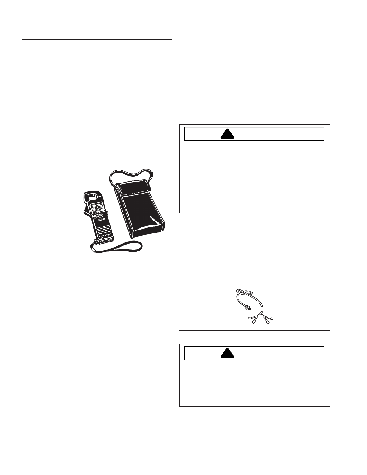
Clamp-On Ammeter
can be used to detect shorts.
Overloads on the circuit breaker
or fuse can be traced
to either the appliance
or circuit breaker by
checking the current
draw.
Each circuit in an appliance has a "Normal" current
draw, which is an indication of the performance of that
circuit. Current draw levels of less than or more than
normal give clues to possible malfunctions. The clampon ammeter measures these circuits without breaking
the circuit by measuring the strength of the magnetic
field developed around each conductor. Current is read
by separating the conductors and clamping the jaws of
the ammeter around each conductor on which current is
read. Low amperage readings indicate problems, such
as damaged heating elements, etc. High amperage
readings indicate the unit being tested is operating under
an increased mechanical or electrical load.
NOTE: Overloads on a circuit breaker or fuse can be
traced to the product being tested or the circuit breaker
(or fuse) by checking the products current draw . If the
amperage reading is less than the breaker reading, the
breaker or fuse box is at fault.
Use of the meter on voltage higher than the
Use of Ammeter on dishwasher:
1. Motor Current - the reading can be taken at the
leads on the motor start relay or at the male connector.
2. Heating Element Current - The reading can be
taken using either lead to the element.
Motor Test Cord
DANGER
!
T o avoid risk of personal injury or death due to
electrical shock:
• Disconnect electrical power to dishwasher before
servicing.
• Always plug test cord into a properly grounded
receptacle.
• Always make connection to components before
plugging test cord into receptacle.
A motor test cord may be used to electrically check
operation of the various electrical components without
removing them from the unit. Testing in this manner
merely determines whether or not the part will function
independently of other electrical components. In order to
make accurate tests, proper connection of the motor test
cord is important. With the aid of the drawings under
Drive Motor Test, installation of the motor test cord may
be done quickly and accurately .
Grounding and Polarity
DANGER
!
T o avoid risk of personal injury or death due to
electrical shock:
• Do not cut or remove the grounding prong from any
plug.
The receptacle used for all Maytag products operating on
120 V AC must be properly grounded and polarized.
The power cord used on the appliances should be
equipped with a three (3) prong polarized grounding plug
8 16022783 Rev. 0 ©2004 Maytag Appliances Company
Page 9
Electrical Equipment & Testing
for protection against shock hazard and should be
plugged directly into a properly grounded and polarized
receptacle.
It is the responsibility of the person installing the
appliance to assure it is adequately grounded and
polarized at the point of installation, taking into
consideration local conditions and requirements. In
cases where only a two (2) prong receptacle is available,
it is the personal responsibility of the consumer to have it
replaced with a properly grounded three (3) prong
receptacle. All grounding and wiring should be done in
accordance with National, State, and Local codes.
NOT USE AN ADAPTER PLUG WITH THIS
APPLIANCE.
DO
ELECTRICAL TESTS
WARNING
!
T o avoid risk of personal injury or death due to
electrical shock:
Wax Motor Check
Detergent / Rinse Aid Dispenser
A single Wax Motor is used to activate both the release of
the Detergent Cup Cover and the rinse aid from the
reservoir.
T o check the operation of the W ax Motor, removal from
the Dispenser Retainer or Inner Door is not necessary .
First, snap the Detergent Cup Door shut. Then, connect
a Power Test Cord across the two terminals of the Wax
Motor. Plug the Power Test Cord into a 120 VA C
receptacle. The plunger in the center of the Wax Motor
should "push out" and actuate the Dispenser in
approximately 45-60 seconds. Remove voltage to the
Wax Motor and allow the plunger to retract into the Wax
Motor. Apply voltage to the W ax Motor again and observe
for proper lifting of the rinse aid plunger .
• Disconnect electrical power to dishwasher before
servicing.
• Always plug test cord into a properly grounded
receptacle.
• Always make connection to components before
plugging test cord into receptacle.
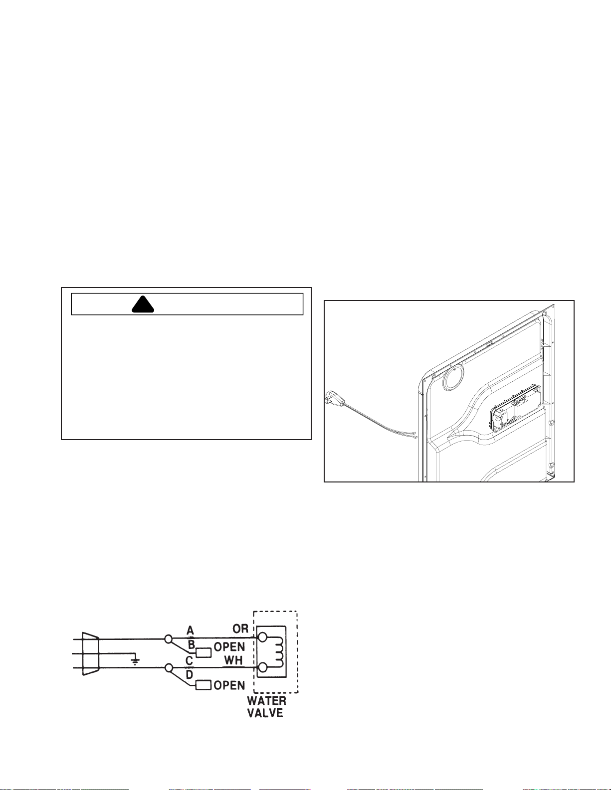
WATER VALVE TEST
The Water V alve may be checked without removing it from
the Dishwasher.
T o check the W ater V alve for operation, hook up the test
cord as follows:
©2004 Maytag Appliances Company 16022783 Rev . 0 9
Page 10
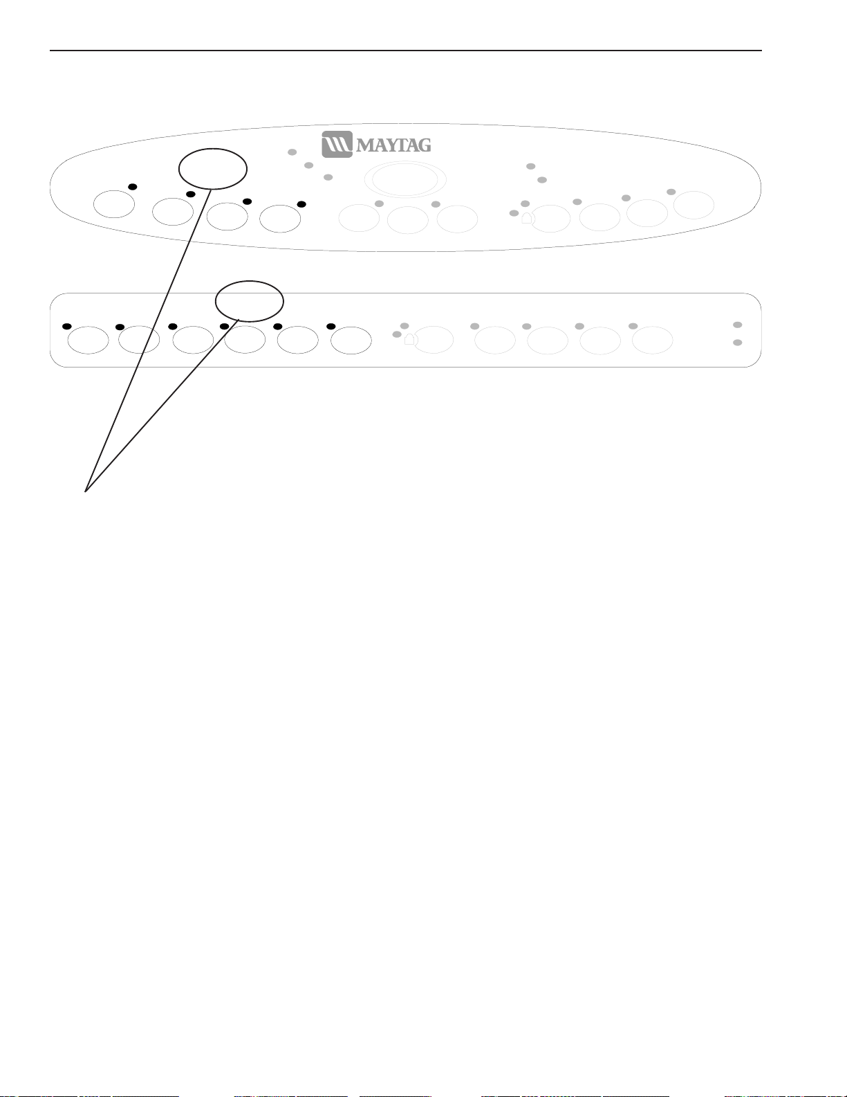
Cycles & Options
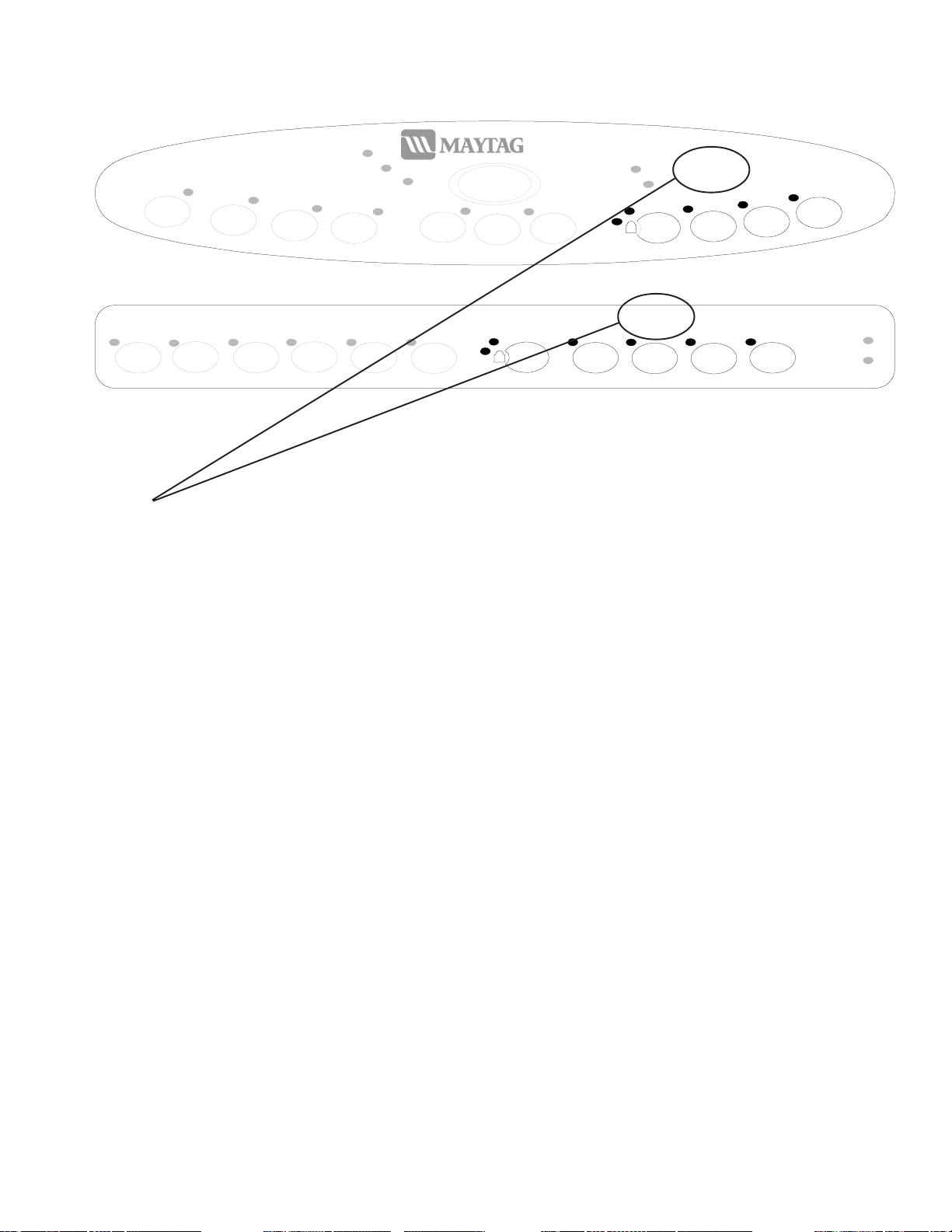
QuietSeries 300
Cancel
DELAY
1-9
Heatin g D e l ay
Sanitized
3
Heated
Dry
Options
Sanitize
Tough
Scrub
Extra
Rinse
Heavy
Wash
Normal
Wash
Cycles
Light
Wash
Washing
Rinse
Only
Drying
Clean
Auto
Clean
START/
Covers all other models
Auto
Clean
Heavy
Wash
Normal
Wash
Cycles
Light
Wash
Rinse
Only
Quick
Wash
3
Heated
Dry
Sanitize
Options
Extra
Rinse
Tough
Scrub
Plus
160°
Wash
Clean
Sanitized
MDB9750 Only
See User's Guide for specific operation.
Cycle Description
Auto Clean Designed to auto select the number of fills and length of wash time based on soil level
of the dish load. Water usage ranges from 3 to 8 gallons.
Heavy Wash Designed to provide a longer cycle for washing items with heavy
food soils. Water usage is 8 gallons.
Normal Wash Designed to wash loads containing dishes with normal amounts of food soils.
Water usage ranges from 3 to 6 gallons.
Light Wash Designed to wash loads containing dishes that are lightly soiled. Water usage is 5
gallons.
Quick Wash Designed for light food soils. The cycle ends with a rinse and does not include drying.
Water usage is 4 gallons.
Rinse Only Rinses dishes being held until the dishwasher is full, and another
cycle is selected. This cycle helps reduce the potential for development of odors.
Water usage is 2 gallons.
10 16022783 Rev . 0 ©2004 Maytag Appliances Company
Page 11
Cycles & Options
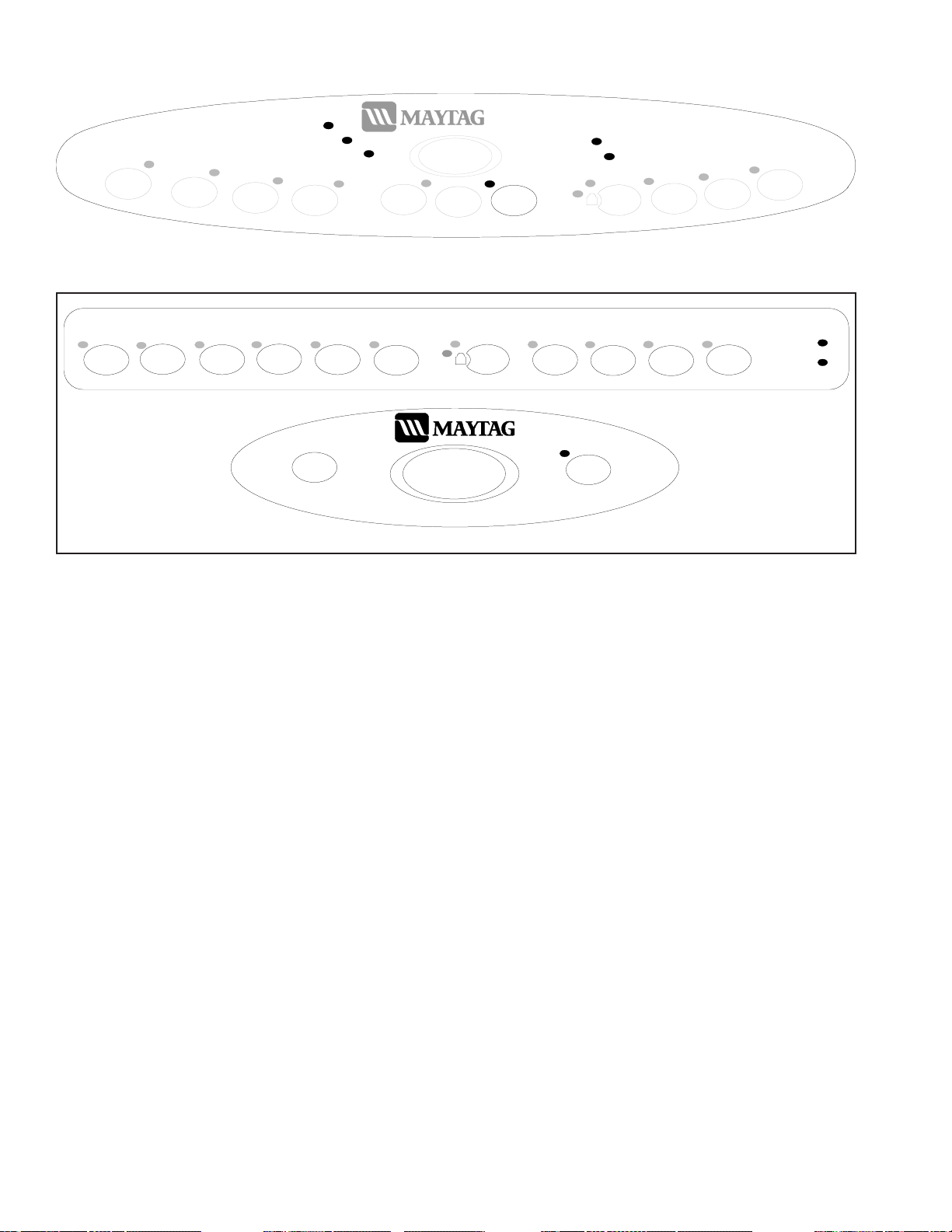
QuietSeries 300
Cancel
DELAY
1-9
Heatin g D e l ay
Sanitized
3
Heated
Heavy
Wash
Normal
Wash
Cycles
Light
Wash
Washing
Rinse
Only
Drying
Clean
Auto
Clean
START/
Covers all other models
Auto
Clean
Heavy
Wash
Normal
Wash
Cycles
Light
Wash
Rinse
Only
Quick
Wash
3
Heated
Dry
Sanitize
Options
Extra
Rinse
MDB9750 Only
See User's Guide for specific operation.
Option Description
T ough Scrub™ This option adds fills, heat and/or wash time to the
T ough Scrub Plus™ wash cycle.
Dry
Options
Sanitize
Tough
Scrub
Plus
Tough
Scrub
160°
Wash
Extra
Rinse
Clean
Sanitized
Sanitize This option monitors cycles for sanitization.
Extra Rinse This option adds an extra rinse to the cycle which helps in hard water situations.
160° Wash This option raises temperature in the final rinse to 160° F.
Heated Dry This option improves drying results by turning the heating element on and off during
the dry portion of the cycle.
Delay Delays the start of the dishwasher based on user input.
Control Lock Lock's the control touch pads from unwanted usage. This option does not lock the
door.
©2004 Maytag Appliances Company 16022783 Rev . 0 11
Page 12
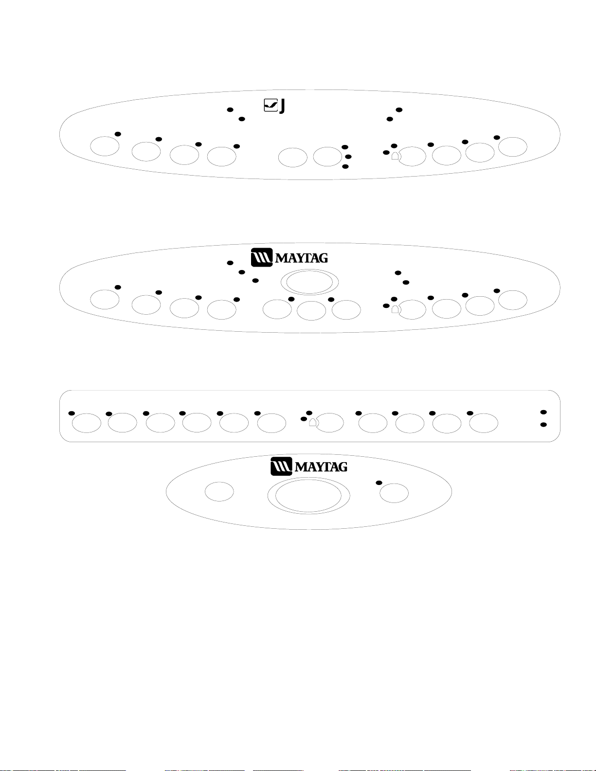
Cycles & Options
Auto
Clean
Heavy
Wash
Heavy
Wash
Normal
Wash
Cycles
Normal
Wash
Light
Wash
Cycles
Light
Wash
Washing
Rinse
Only
START/
Cancel
Drying
Rinse
Only
Clean
Auto
Clean
START/
Covers all other models
Quick
Wash
QuietSeries 300
QuietSeries 300
Cancel
Heated
3
Dry
DELAY
1-9
Heatin g D e l ay
Sanitized
Sanitize
DELAY
Heated
3
Dry
Options
Extra
Rinse
1-9
Options
Sanitize
Tough
Scrub
Plus
Tough
Scrub
160°
Wash
Extra
Rinse
Sanitized
Clean
MDB9750 Only
Display Description
Clean The "Clean" light illuminates at the end of the cycle and remains on until the door has
been open continuously for 30 seconds.
Drying The "Drying" light illuminates until the cycle is complete.
Washing The "Wash" light illuminates through all the rinse and wash portions of the cycle.
Heating Delay The "Heating Delay" light illuminates when the cycle is being extended to heat the
water.
Clean/Sanitized These two lights illuminate from the end of cycle until the next cycle is selected,
or the door has been open continuously for 30 seconds.
Delay The "Delay" light will illuminate whenever a delay count down is in progress, or until
the "Delay" pad is pressed again.
12 16022783 Rev . 0 ©2004 Maytag Appliances Company
Page 13
Cycles & Options
Heavy
Wash
Heavy
Wash
Normal
Wash
Normal
Wash
Cycles
Light
Wash
Cycles
Light
Wash
Washing
Rinse
Only
Washing
Rinse
Only
Drying
Drying
Clean
ENN-AIR
START/
Cancel
JDB1060
Auto
Clean
START/
Cancel
MDB8750
2-4-6
2
4
6
DELAY
QuietSeries 200
Heatin g D e l ay
DELAY
1-9
Sanitized
Clean
Sanitized
3
3
Heated
Dry
Heated
Dry
Options
Sanitize
Options
Sanitize
Tough
Scrub
Tough
Scrub
Plus
Extra
Rinse
Extra
Rinse
Auto
Clean
Heavy
Wash
Normal
Wash
Cycles
Light
Wash
START/
Cancel
Rinse
Only
Quick
Wash
3
QuietSer ies 300
MDB9750
Heated
Dry
Sanitize
Options
Extra
Rinse
DELAY
1-9
Tough
Scrub
Plus
160°
Wash
Clean
Sanitized
©2004 Maytag Appliances Company 16022783 Rev . 0 13
Page 14
Electrical-Mechanical Troubleshooting
!
T o avoid risk of electrical shock, personal injury , or death, disconnect electrical power source to unit and discharge
capacitor through a 10,000 ohm resistor before attempting to service, unless test procedures require power to be
connected. Ensure all ground wires are connected before certifying unit as repaired and/or operational.
!
Units covered in this manual are polarized. Reversing polarity of a unit or any of its components will cause
damage. T o avoid reversing polarity , any wires disconnected or removed during service must be reconnected to the
same location. T o ensure wires are reconnected to the proper location, t ag or otherwise mark the wires before
disconnecting or removing.
Will Not Fill
Water Access Valve
Check to determine if the valve is turned on and water is
available to the Dishwasher. Check water pressure.
Circuit Breaker/Fuse
Check for tripped breaker or blown fuse. Reset or replace
as necessary .
Door Latch
Check door switches for continuity . With door switches
engaged, no continuity , replace switch.
Float
Check float position. If in the up position, check for
obstruction or disengagement from the Float Switch Arm.
WARNING
CAUTION
NOTE: Low water pressure can result in failure of the
Water V alve to close properly .
Float
Ensure that the Float isn't stuck in the down position.
Check for sediment buildup. Clean and/or replace as
necessary .
Float Switch Actuator Lever
Check the actuator lever on the bracket. It must be able
to move freely . Repair or replace as necessary . (See
section 5).
Float Switch
Check Float Switch for continuity with the Float in the up
position. If continuity is present and Float moves up and
down freely , replace Float Switch.
Float Switch
If the float is in the down position, check the switch for
continuity . If no continuity, replace the Float Switch.
Water Valve
Check Solenoid for continuity . No continuity , replace
Water V alve. Check Inlet Screen for restrictions. Clean
screen or replace Water V alve as necessary. (See section
5).
Wiring/Electrical Connections
Check for loose or frayed wire terminal connections.
Check for broken wire within harness. Repair or replace
as necessary .
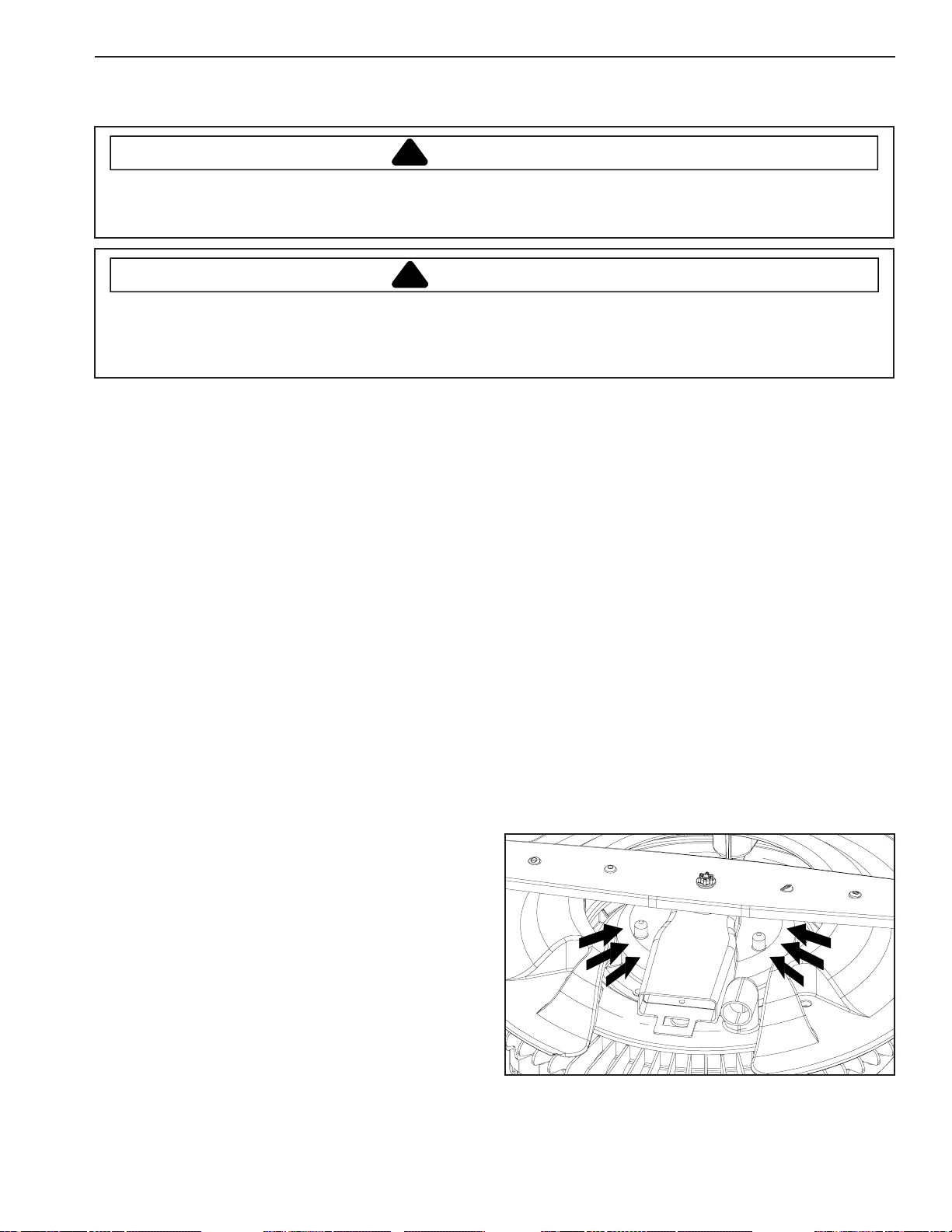
Water Level - Too Low
Normal water fill should be at level depicted by arrows.
POOR WATER CIRCULATION
Overflows
Water Valve
Check that water continues to flow when electrical power
is turned off. If the water continues to flow without
electrical power, replace W ater V alve.
©2004 Maytag Appliances Company 16022783 Rev. 0 14
Pump Assembly
Check assembly for obstructions or restricted movement
of parts. Repair and/or replace part s as necessary .
Page 15
Electrical-Mechanical Troubleshooting
!
T o avoid risk of electrical shock, personal injury , or death, disconnect electrical power source to unit and discharge
capacitor through a 10,000 ohm resistor before attempting to service, unless test procedures require power to be
connected. Ensure all ground wires are connected before certifying unit as repaired and/or operational.
Filters
Check for blockage of Strainer , Over Pressure Filter .
Repair as necessary .
Poor Washability
Spray Arms
Check all Spray Arms for blockage of water ports or
cracks. Check for proper rack loading to avoid interference
with Spray Arms during wash action. Check for proper
sealing, fastening, and movement of Spray Arms. Repair
as necessary .
Filters
Check for blockage of Strainer , Primary Filter , and Filter
Support. Repair as necessary .
WARNING
Pump Assembly
Check pump assembly for obstructions or restricted
parts. Repair or replace parts as necessary.
Wiring/Electrical Connections
Check for loose or frayed wire terminal connections.
Check for broken wire within harness. Repair or replace
as necessary .
Continues To Drain
Control Board
Check Control Board for proper operation.
Poor Drying
Detergent Cup Cover
Check spring hinge operation of Detergent Cup Cover.
Repair as necessary .
Detergent Cup
Check operation of Detergent Cup Assembly , W ax Motor ,
Actuator, Linkage, and Cover Latch. Repair and/or replace
parts as necessary. Note: For testing of Wax Motor, see
Section 2.
Rinse Dispenser
Check level of rinse aid in reservoir. Check rinse aid
dispenser setting.
Wash Delivery System
Check manifold and Docking Station for good seal and no
leaks.
Will Not Drain
Inadequate Drainage
Check Drain Pump for proper operation. Check the drain
pipe connections and repair as needed. If draining into the
garbage disposal, check for unprocessed food waste at
drain hose connection to disposer. Clean out as needed.
Drain Hose
Check drain hose for kink or restrictions. Reroute or
remove any restriction of drain hose as needed.
Water Temperature
Check for low water temperature. T emperature should be
between 120 - 150 degrees Fahrenheit. If not, advise
consumer to adjust water heater setting. Encourage
consumer to purge water lines to the dishwasher area
prior to starting the dishwasher.
Cycle Options
Advise consumer use of options available on dishwasher
that improve drying. Options that improve drying are
Heated Dry , and 160° Wash.
Detergent
Check water hardness. Instruct consumer on detergent
usage, one teaspoon of detergent per grain of water
hardness.
Rinse Dispenser
Check level of rinse aid in reservoir. Check dispenser
setting under cap. Use "MAX" for hard water conditions.
Improper Rack Loading
Check how the consumer loads the dishes into the racks.
Improper loading of some types of dishes can trap water
which causes dishes not to dry .
Heating Element
Check load readings listed on T echnical Sheet located
behind T oe Panel.
15 16022783 Rev. 0 ©2004 Maytag Appliances Company
Page 16
Electrical Mechanical Troubleshooting
!
T o avoid risk of electrical shock, personal injury, or death, disconnect electrical power source to unit and discharge
capacitor through a 10,000 ohm resistor before attempting to service, unless test procedures require power to be
connected. Ensure all ground wires are connected before certifying unit as repaired and/or operational.
Thermostat
Check mating surface of the High Limit Thermostat face
to surface of tub enclosure. Contact area must be flat.
Adjust the thermostat placement if necessary . See
T echnical Sheet, located behind Toe Panel for thermostat
data.
Water Leaks
Installation
Check Dishwasher for proper leveling and squareness in
cabinet.
Door Alignment
Check proper alignment of Door Liner to Door Gasket.
Door Gasket
Check for torn or damaged Door Gasket. Repair or
replace as necessary .
Hoses
Check for loose hose clamps or hoses that leak. Tighten
hose clamps or replace hoses as needed.
WARNING
Noise
Banging
Check for loose Spray Arms. Check for dishes interfering
with Spray Arm rotation. See loading information in the
User's Guide at the end of this manual.
Hammering/Chattering
Check Water V alve for , noise, low voltage, or high valve
coil resistance. Replace Water Valve if needed. Also,
check incoming water supply line for proper size and
pressure. Make sure the supply line is secured.
Grinding
Check for objects in Pump Assembly. If objects are
found, inspect Pump Assembly for damage. Rep air as
needed.
Vibration
Check components for source of vibration. Adjust and/or
tighten as needed.
Will Not Start Or Program
Spray Arms / Manifold
Check for cracks and replace as necessary .
Detergent / Rinse Aid Dispenser Seal
Check Rinse Aid Dispenser Seal for proper positioning or
cracking. Reposition or replace as needed.
Water Valve
Check Water V alve body for damage and leaks. Replace if
necessary. Also, check plumbing connections to Water
V alve.
Wash Motor Assembly
Check for water leak between Pump Assembly and tub.
Drain Pump Assembly
Check Pump Assembly Housing for cracks. Check Drain
Pump "O" ring for leaks.
Control Board
Check incoming voltage to Control Board.
Membrane Switch
Check for proper operation of Membrane Switch. See
membrane readings on the T echnical Sheet located
behind toe panel.
NOTE: Make sure the pin connectors are making proper
contact with pins on the Control Board. If the
voltage is correct into the Control Board, and the
board will not activate, replace board.
Will Not Fill
Water Valve
Check Water V alve circuit. See Technical Sheet for water
valve data located behind toe panel.
NOTE: Make sure the pin connectors are making proper
contact with pins on the Control Board.
©2004 Maytag Appliances Company 16022783 Rev. 0 16
Page 17
Electrical Mechanical Troubleshooting
!
T o avoid risk of electrical shock, personal injury , or death, disconnect electrical power source to unit and discharge
capacitor through a 10,000 ohm resistor before attempting to service, unless test procedures require power to be
connected. Ensure all ground wires are connected before certifying unit as repaired and/or operational.
WARNING
Will Not Wash
Wash Motor
Check Wash Motor circuit. See data listed on the
T echnical Sheet, located behind toe panel.
Will Not Drain
Drain Motor
Check Drain Motor circuit. See data listed on the
T echnical Sheet, located behind Toe Panel.
Will Not Dry
Vent Assembly
Check Vent Assembly for proper operation.
Heating Element
Check Heating Element circuit. See data listed on the
T echnical Sheet, located behind Toe Panel.
Manual Function Test
See T echnical Sheet, located behind T oe Panel.
Field Service T est
See T echnical Sheet, located behind T oe Panel.
17 16022783 Rev. 0 ©2004 Maytag Appliances Company
Page 18
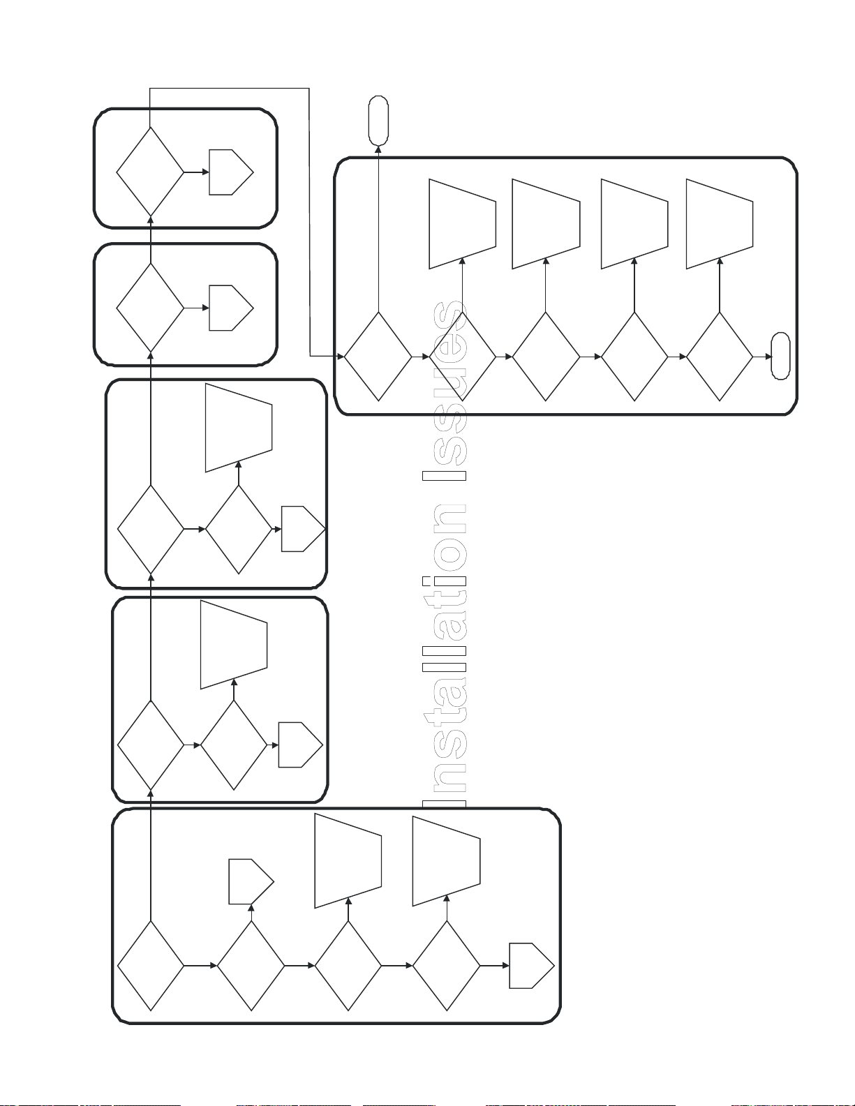
Troubleshooting Flow Chart
No
Yes
Go to
Noise
Issues flow
chart
Complete
Noise Problem
No
Are there any leaks? Is it noisy?
Leak Problem
Drain Problem
Yes
properly?
Does it drain
Yes
Does it fill properly?
Starting Problem Fill Problem
Yes
pressed?
cancel key is
when the start/
Does the cycle start
Yes
No
No
No
chart
Go to Leak
Issues flow
drain
system
Repair or
reconfigure
No
and air break
Are the drain line
operating correctly?
on
Turn water
No
on to the unit?
Is the water turned
Fuction
Go to No
flow chart
Yes
Are any of the
indicator lights for
cycle and options
illuminated?
Yes
Fuction
Go to No
flow chart
Yes
Fuction
Go to No
flow chart
Verify wiring
No
correctly at
junction box
is connected
No
breaker panel or
Is the power turned
on to the unit at the
Yes
Appearance Problem
in the installation?
Does it look correct
power
and turn on
fuse box?
©2004 Maytag Appliances Company 16022783 Rev. 0
It is
unit
extremely
LEVEL the
important to
No
No
Is the unit level left
home
Correct
wiring issue
No
Yes
(minimum) at
junction box?
Is there 105VAC
Yes
to back?
to right and front
Yes
Go to No
Adjust to
touch floor
No
Do all 4 levelling
Fuction
flow chart
and
recheck
legs touch the floor?
levelness
Repair
cabinets
No
Yes
Are the cabinets
Yes
level and plumb?
strips
Install trim
No
side and top?
installed on each
Are the trim strips
Yes
Complete
18
Page 19

Troubleshooting Flow Chart
Check
below
manual
for leaks
operation
after each
Leaks
No
Top of the Door
Yes
top of the door?
Is there a leak at the
16022783 Rev. 0 ©2004 Maytag Appliances Company 19
Normal
Operation
Yes
No
Does it leak when
you open the door?
recheck
seal and
Adjust foam
Yes
No
eyelets?
Can you see foam
material in the vent
foam seal
Install new
No
Yes
panel?
vent and control
Is the rectangular
installed between
foam seal correctly
Complete
Page 20

Troubleshooting Flow Chart
Loosenclamp,push fillhose onand fullyreseatclam
p
Is the air/water inletfoam in place?Reseat/replacefoa
m
Removeandreinstall air/water inle
twith n
ew o-ringNoN
oNoYes
RepairconnectionN
oIs the leak comin
g
the rear behindthe main washmotor?Are the heater nutsfully seated/tighted?Is the heater itselfleaking?Is there a crack inthe tub
wall near thel
ower rear corners
?
YesYesYesYesYesNoNoNoNoCompleteIs the air
/water inletbezel present?InstallbezelN
oCompleteYes
Removeandreinstallheater nutsComplete
From Page 1
Replacethe heaterReplaceuni
t
clamp
Tighten the
No
Yes
clamp tight?
Is the drain hose
Yes
A
Is the drain pump to
No
drain hose leaking?
Repair
connection
Yes
From Page 1
B
leaking?
Is the incoming
water under the sink
©2004 Maytag Appliances Company 16022783 Rev. 0
No
Yes
Is the water valve
clamp fully seated?
Replace
the hose
Yes
No
end?
Is the fill hose
leaking at either
No
attached to
Is the other end of
the fill hose securely
Complete
Yes
going into the
Is the drain hose
plumbing leaking?
plumbing?
Yes
inlet?
Is water splashing
out of the air/water
No
Complete
leaking at the tub
Is the air/water inlet
Yes
connection?
from
20
Page 21

Troubleshooting Flow Chart
Cycle Selection
Problem
16022783 Rev. 0 ©2004 Maytag Appliances Company 21
Page 22

Troubleshooting Flow Chart
Is there 105VAC(minimum) to thejunction box?RepairinstallationproblemNo
r o
r
c
e
ssYes
o
Door or Latch Problem
Verify the door is onboth hinges, bothdoor springsare attachedcorrectly,and installationis correct
Is there a proble
mwith the rack?NoNoYesYesYesReplacerackNoNo
Rack Proble
m
A
djust tosameheightIs there a brokenpart?Orderreplace-ment partIs it hard to move inor out
?
e rac
k
lock int
o
ce?Replaceracka
djustersNoWill the rack slide allthe way in?Removeitem that isblockingrackYesNoYesIs food trapped inrack slides?RemovefoodNoIs rack
warpedcausing it to bindYesBend backif possibleor replaceAre bolts in tu
bwheels tight?TightenboltsYesNoYesYesSnapsnuggers torackAre snuggers atback of rack fullysnapped to rack?YesNo
Dispenserproble
m
re a proble
m
he dispenser?See "A" infl
ow chartWashPerformanceCompleteNoYe
s
FromPage
1
No
height?
Are both sides
adjusted to same
No
latch?
Is there a problem
with the door or door
A
Replace
Drain Problem
No
draining the unit?
Is there a problem
C
From
Page 1
No
Yes
Will the door clo se
drain pump
See Wash
Yes
Yes
and latch
completely?
Yes
Flow Chart
Performance
Yes
bottom?
front of tub or door
Is there food soil at
pla
Will th
adusters
wire
repla
harne
Repai
striker
replace
latch or
Repair or
Yes
striker broken?
Is the door latch or
drain cycle?
drain pump during
Is there 105VAC to
No
No
drain only cycle?
come on during a
Will the drain pump
replace
Repair or
door switch
No
No
correctly?
Do both door
switches work
No
Control
Replace
Yes
Yes
Is the carry over
©2004 Maytag Appliances Company 16022783 Rev. 0
N
Yes
Is there 105VAC
J5, pin 8 & ST-10?
(minimum) between
No
Yes
With the door switches
(minimum) between ST-
closed, is there 105VAC
Unclog
Yes
No
correct?
volume after the
cycle is complete
Is the drain pu mp
Yes
board?
3 & ST-11 on control
drain pump
clogged?
start after
If the unit won't
No
control
cancel key
then replace
multiple times
pressing the start/
Is the
with t
drain
valve
Level unit
No
Is the unit level?
Replace
Yes
Yes
Is the drain outl et
check valve stuck
No
open?
From
Page 1
system
Repair or
reconfigure
No
Yes
Wash
flow chart
and air break
Are the drain line
operating correctly?
B
See "A" in
Performance
22
Page 23

Troubleshooting Flow Chart
y spotting,
NoIs it only tall glassesOnlyloadshortYes
in the corners?items inthecorners
Incoming water tempmust be 120°For grater (at sink)
Spotting, Filming,Etching, & CornerIssues
Steps
Important 1st
No
Go to
Function
flow chart
No
Yes
the machine?
Are there staining
issues with parts of
Yes
No
Is the wash
performance good?
16022783 Rev. 0 ©2004 Maytag Appliances Company 23
Only Task
Technician
Yes
over time
will discolor
Accessories
binding or hitting
with
Use a
bleach
detergent
Yes
No
door?
Are there staining
issues with the tub or
No
Yes
wet?
Are the items getting
Are the wash arms
No
Are there items
blocking the wash
No
Can the wash arms
No
No
rack?
Yes
Are the
filming, or etching?
Glasses
arms?
rotate freely?
Sanitize Issues
getting clean?
What items are not
bottom
Tub or door
Yes
Sanitize
Issues
Tub/Door
Soil left on
Heavy
try heavy cycle
Normal operation
other
Dishes,
flatware, or
A
On Page 2
Page 24

Troubleshooting Flow Chart
ethin
g
th
e
door?
s
eplac
eheater or
rmostat
N
o
If the dispenser didnot open repairor replace
Is the carry overvolume correct?LevelunitNoYe
s
surface of
housin
g
" bel
ow to
p
of DHIs the drain pumpclogged?Complete
Pump & Valve Issues
Is the unit level?Is the drain outletcheck valve stuckopen?
ressurewithin tolerance?CorrectpressureNoIs the unit level?No
usin
g
ic D/WRefer t
o
FromPage
1
ent?U & C
rNoNo
Wash/Drai
n
YesNoYesYesYesNoYes
Refer to U & C forR/A & DetergentrecommendationsDeterminewaterhardness?Replac
ewatervalveUnclogdrainpumpLevelunitReplacevalveIs the floatlimiting thefill? Repairor replace floatNo
Water & Detergent
A
Isolated Redeposit/
Original Soil Issues
From
Page 1
B
©2004 Maytag Appliances Company 16022783 Rev. 0
Is the water p
No
Is the fill volume
water
Increase
Yes
Issues
Is the incoming water
No
Are any of the spray
No
Are items nested
together, touching
No
Is the redep
Yes
within tolerance?
120F
temp to
No
< 120F?
temperature (at sink)
nozzles clogged?
path?
other items, or
blocking the spray
everywhere?
wate
surface
discharge
2 Rack - 1/4
3 Rack - Top
Back
again
and try
Change
Yes
No
Have you changed
detergent recently?
Yes
Yes
spray
Unclog
nozzles
remove
seeds, &
from load?
large soils,
Be sure and
hard objects
Heavy/Random
load to
problem
eliminate
Rearrange
Yes
Yes
Remove
obstruction
No
blocking
dispenser
Is there som
Yes
No
R
Did the detergent
completely dissolve?
filter
Replace
Redeposit Issue
Yes
No
it torn?
Remove filter guard &
inspect filter mesh. Is
Clear
Yes
the
No
Yes
working?
Is the heater
port
sample
No
clogged?
Is the sample port
Are you
automat
filter
Install
flapper
No
present?
Is the filter flapper
Yes
deterg
ears
Insert
flapper
No
Yes
Yes
port opening?
Are all 4 flapper ears
inserted into the drain
24
Page 25

Troubleshooting Flow Chart
Instruct toloaddifferentl
y
wate
r
t 120F?Instruct toraise
watertemp forbetterperformanceIs the consumer onlyhaving problem
swith plastic or Teflonitems?Instruct thatthese itemswill not getdry in anymachineIs the consumer onlycomplaining aboutwater droplets onthe tub and innerdoor?Instruct thisis normaloperationandsuggestovernightdryin
g
IMPORTANT
Refer to U & C forR/A & Detergentrecommendationsbased on waterhardnes
s
Customer Instruct IssueCycleSelectionVentRinse AidLoadingWater TempOp NormalSee Page
2
wire
chart
This flow
checked
have been
assumes all
connections
16022783 Rev. 0 ©2004 Maytag Appliances Company 25
load
Instruct to
differently
No
Yes
and oriented
collecting water?
Are items spaced
properly to reduce
for better
Instruct to
Dry" option
use "Heated
performance
No
selected?
Dry" option
Was the "Heated
No
the racks?
cups located on
Are glasses and
slanted sections of
"Sanitize" or
"160 Degree"
Instruct to use
No
Yes
Was the sanitize
No
Yes
Is incoming
better
option (if
performance
available) for
Yes
option selected?
Instruct to
move items
Is anything blocking
Yes
temp at leas
vent
openings
away from
Yes
No
the control panel?
the vent openings in
Yes
No
Aid
Instruct to
use Rinse
No
Yes
used?
Is Rinse Aid being
Yes
No
Increase
Rinse Aid
created
too much
foam isn't
setting by 1
making sure
No
Yes
Is the Rinse Aid
setting on MAX?
Page 26

Troubleshooting Flow Chart
Repair orreplace asnecessar
y
gh limi
t
t bee
n
d?Verify it hasnot failed inthe openposition andis sitting on aflat surfaceYesYesYesNoNoNo
V
ent BezelVentHigh Limit Thermosta
t
operation o
f
ing element
verified?Run FieldService testand verifycorrectoperationHas the operation ofthe Turidity Sensorbeen verified?Has the voltagebeen checked to theunit?Less than115VAC cannegativelyaffect thedryingperformanceHas the operation ofthe Rinse AidDispenser beenverified?Run FieldService testand verifycorrectoperationRun FieldService testand verifycorrectoperationCompleteYesYesYesYesNoNoNoN
o
Functional IssueHeaterR
/ADispenserTurbiditySenso
rVoltag
e
and
reinstall
Remove
vent bezel
No
Yes
the inner door
installed flush?
Is the vent bezel on
©2004 Maytag Appliances Company 16022783 Rev. 0
been
the heat
Has the
No
Yes
bezel oriented
toward the bottom?
Is the slot in the vent
operation
Run Field
and verify
wax motor
Service test
been verified?
the vent wax motor
Has the operation of
Is the vent flapper
operating correctly?
checke
thermosta
Has the hi
From Page 1
26
Page 27

Troubleshooting Flow Chart
Instructcustomerandrearrangeite
m
r
Complet
e
H
owling/Surgin
g
YesComplete
Are there excessiveleaks at hubs ordistribution system?Are there objectsbetween chopperand chopper plate?
Is there anexcessive amount offoaming in unit?to use less RinseAid. See U&C forrecommendeddetergentamounts basedon
waterhardnessYesYesNoVerifyRinse Aidtank is notleakingRepair orreplaceIs the tub rear wallCheck allmanifoldhar
dwarefor correctoperationandplacementNobowed in?Verifynothing isprotrudingfrom backwall intoback of tubdocking ports out ofDisassemble,look for partsthat haverubbedtogether andrealign orreplaceNoYesN
o
Are the flappersfrom the unusedplace, missing, ordeformed?Repair or"WashChart" Fl
owreplaceYe
s
m
e 2
DDoes it sound likean intense grindingor buzzing?Look for hardo
bjects betweenchopper andchopper plate
.
Grinding/Buzzin
g
YesYesNoRemove itemsand instructcustomertoscrapehard o
bjects Does it sound like aringing noise incadence with thewash arm?This iscaused b
ywaterhitting apan and isnormal
Ringing
YesAre pump rotatingparts rubbingstationary parts?YesNoNoNoDisassemble,Togetherand realign or replacelook for partsrubbin
g
16022783 Rev. 0 ©2004 Maytag Appliances Company 27
Pump & Valve
See "Wash/Drain
Issues" portion of
Performance
Yes
Fro
Pag
No
Did the noise stop?
back?
going all the way
Are there objects
keeping rack from
No
From Page 2
C
hand
Add 2
water by
quarts of
Are the wash tubes/
No
Yes
followed by a fill?
Does it surge a few
times and then drain
No
noise?
howling/surging
Does it sound like a
Wash
During
A
No
Does the noise only
On Page 2
Yes
cycle?
portion of the
occur during the
wash
No
3 times during a cycle.
Control is going into the
can occur a maximum of
foam guard routine which
B
Thumping/
?
thumping or
clicking
Does it sound like a
steady
No
Modify
During Fill
fill
occur during the
Does the noise only
portion of the cycle?
Hissing
Yes
Yes
correctly?
manifolds docking
etc.
in too much air which
This occurs when the
low water, out of level,
main wash pump draws
can be caused by foam,
On Page 2
arm
items to
Relocate
avoid spray
Clicking
Yes
Yes
Is the spray arm
home
eliminate
reduce or
plumbing to
Yes
No
noise?
hissing
Does it sound like a
No
rack?
hitting items in the
able to
May be
eliminate
reduce or
Yes
Does it sound like a
objects
instruct
Remove
items and
customer to
scrape hard
Yes
No
Yes
Instruct custome
rack
replace
or load or
Adjust rack
Yes
No
hitting the rack?
Is the spray arm
by
plumbing
modifying
noise?
thumping
Thumping
No
racks
secure
items in
load and
Rearrange
Yes
each other?
Are items moving
around and hitting
water
Install a
hammer
suppressor
Complete
No
Are seals or
mechanical parts
rubbing together?
No
load to
Instruct
No
to eliminate
coming
block jets
rearrange
customer to
wash arm
from lower
Yes
No
Is the upper spray
arm hitting the tub?
parts
Adjust,
replace
realign, or
Yes
filter cover?
arm hitting the
Is the lower spray
heater element or
Yes
No
arm hitting
Is the lower spray
Single
Thump
No
racks?
fallen through the
something that has
cup lid
normal
detergent
This is the
operation
hitting the
door and is
Yes
during
No
final rinse?
Does it sound like a
single thump
Page 28

Troubleshooting Flow Chart
Removeo
bject
s
Replacewash arm
Yes
YesYesYesYe
s
o
On Page 1
1
Yes
Verifynothing i
swedgedbe
tweendrain pumpand floo
r
it sound like a noise?
ndingRemovehard o
bjectfrom drainpumpDoes the after water isfully drained?noise getlouderInstructcustomerthis isnormaloperationComplet
e
d like
a
ise
?
Does it sound like a noise?grinding
DoorBuzzingVibratingHummingGrindingLoudPoppingGrindin
g
YesYesYesYesYesYesYesYesYesNoNoNoNoNoNoNoYe
s
Opening/Closing
With the door fullyopen, is the front lipof the tub visible?Does the deco panelinterfere with thehinge in the l
owercorners?Is the door installedon the hingesproperly?Are the springs orcables rubbingagainst the cabinetor the machine?
CompleteDoes the noise onlyoccur while movingthe in or out? rac
k
Moving Rack
YesYesYesYe
s
FromPage
1
This isdetergentcup lidhitting doorand isnormalReplaceinner doorA
djust orreplace asneccessaryInstall dooron hingesAdjust orreplacePlace cableback onpulleyComplet
e
Yes
flow chart
See "Rack
No Function
of
Problem" section
Does it occur one
NoNo
?
opening
No
wash?
time only after a
no
No
No
No
Yes
No
Are the cables off
No
the pulleys?
or closing door
Does the noise only
occur while
No
cycle?
portion of the
occur during the
drain
Does the noise only
adjust
Realign or
noise
pieces?
buzzing
Does it sound like a
between sheet metal
popping
Does it soun
Readjust
insulation
or reroute
drain hose
noise?
vibrating
Does it sound like a
humming
noise?
constant
Does it sound like a
gri
Does
During Drain
A
C
On Page
Yes
Rattling
Does it sound like a
No
noise like
pebbles being
thrown around?
rattling
D
station
replace
docking
Repair or
N
with docking?
Is there a problem
Yes
No
against
water
tub?
consistenlty
spraying
Does it sound like
an intensejet
No
blocked or
Is wash arm
hitting rack?
Yes
docking stations?
Is there a leak in the
No
hitting rack
slow, blocked, or
Are the wash arms
stopped or rotating
Replace
wash arm
No
Water
No
seam?
wash arm weld
Is there a leak in the
Spraying
replace
wash arm
Tighten or
replace
wash arm
Tighten or
No
stationary and
stuck between
at a wash arm hub?
Is there a large leak
Are there objects
No
Complete
Yes
wash arm hub?
rotating parts of the
No
seam?
wash arm weld
Is there a leak at the
Complete
No
at a wash arm hub?
Is there a large leak
fillers
or add
change
Instruct to
installation
During Wash
If motor is
stays level
touching floor
raise machine
making sure it
No
Yes
Humming
From
Page 1
B
noise?
humming
loud low frequency
Does it sound like a
Adjust
water valve
Yes
touching the tub?
Is the water valve
No
©2004 Maytag Appliances Company 16022783 Rev. 0
loop
correct
remains
Reroute
enusuring
drain hose
Yes
rubbed
replace
that have
realign or
together and
look for parts
Disassemble,
Yes
Repair
installation
Yes
& 2 foam pieces
installed correctly?
Are all 3 trim strips,
2 parts of kick plate,
Loud
No
wedged tightly
Is the drain hose
No
cabinet/wall?
between tub and
parts rubbing
Are pump rotating
No
stationary parts?
Is the door or other
part of the machine
No
cabinet?
forced against
Consistently
Yes
sound
too loud?
Is the overall
consistent
Yes
Yes
between the
cabinet/wall?
machine and the
Are there large gaps
No
No
Complete
seal or
normal
Replace
operation
instruct as
Yes
Squeaking
No
sound as
stop?
Does it sound like a
sqeaking
machine coasts to a
28
Page 29

Service and Disassembly Procedures
! WARNING
To avoid risk of electrical shock, personal injury, or death, disconnect electrical power source to unit and discharge
capacitor through a 10,000 ohm resistor before attempting to service, unless test procedures require power to be
connected. Ensure all ground wires are connected before certifying unit as repaired and/or operational.
The following paragraphs describe how to disassemble
unit under test. Disassembly to some extent is required
to install unit, to perform troubleshooting procedures, and
to remove and replace failed components.
Component names used throughout disassembly
procedures are the same as those used in Parts
Manuals.
For quicker reassembly, disassemble unit under test only
to extent necessary to troubleshoot and repair. Unless
noted, reassembly is opposite of disassembly.
WARNING!
To avoid risk of personal injury or death due to
electrical shock, ground wires and wires colored like
ground wires are NOT to be used as current carrying
conductors. The standard accepted color coding for
ground wires is green or green with a yellow
stripe. Electrical components such as the water valve
and motor are grounded through an individual wire
attached to the electrical component. Ground wires
should not be removed from individual components
while servicing, unless the component is to be
removed and replaced. It is extremely important to
replace all removed ground wires before completing
service.
Front Support and Toe Panel Removal
Removal of Front Support and Toe Panel will allow access
to the Water Valve, Float Switch Assembly, Electrical
Junction Box, hoses, thermostats, Start Capacitor and
Motor/Pump Assembly.
Removal
1. Disconnect power to the machine.
2. The Front Support Panel is held by 2 screws, one
each side. Remove both screws.
3. The Toe Panel is held by 2 screws, one each side.
29 16022783 Rev. 0 ©2004 Maytag Appliances Company
Page 30

Service and Disassembly Procedures
! WARNING
To avoid risk of electrical shock, personal injury, or death, disconnect electrical power source to unit and discharge
capacitor through a 10,000 ohm resistor before attempting to service, unless test procedures require power to be
connected. Ensure all ground wires are connected before certifying unit as repaired and/or operational.
Inner Door Panel
Removal of the Inner Door Panel will allow access to the
Microprocessor Board, Door Switches, Detergent / Rinse
Aid Dispenser, and Vent Assembly.
Removal
1. Disconnect power to the machine.
2. Open the Dishwasher door.
3. Remove the 11 Torx™ screws along the sides and
top of the Inner Door Panel.
4. Separate the Inner Door Panel from the Outer Door.
5. Disconnect wires from the Dispenser Wax Motors
before pulling the Inner Door Panel away from the
Dishwasher.
IMPORTANT: When replacing Inner Door Panel, remove
Inner Door reinforcement, Bottom Seal and install on
new panel.
Detergent / Rinse Dispenser Mechanism
and Reservoir
Checking Operation
1. Disconnect power to the machine.
2. Remove the Inner Door Panel. (See paragraph Inner
Door Panel removal).
3. Snap the Detergent Door shut.
4. Gently lift the lever of the dispenser mechanism until
a click is herd. The Detergent Door releases. Release the lever.
5. Lift the lever again. Now the actuator will lift the Rinse
Aid Plunger.
©2004 Maytag Appliances Company 16022783 Rev. 0 30
Page 31

Service and Disassembly Procedures
! WARNING
To avoid risk of electrical shock, personal injury, or death, disconnect electrical power source to unit and discharge
capacitor through a 10,000 ohm resistor before attempting to service, unless test procedures require power to be
connected. Ensure all ground wires are connected before certifying unit as repaired and/or operational.
Wax Motor Detergent / Rinse Dispenser
Removal
1. Disconnect power to the machine.
2. Remove the Inner Door Panel. (See paragraph Inner
Door Panel removal).
3. Remove the 6 mounting screws securing the
Detergent Dispenser mounting bracket.
4. To remove the Wax Motor, pry out of retainer.
NOTE: It is not necessary to remove Detergent
Dispenser before removing Wax Motor.
Wire Cover
The Wire Cover retains the Wire Harness to the bottom of
the Tub. It is located on the bottom side of the Tub.
Removal
1. Disconnect power to the machine.
2. Remove Front Support and Toe Panel. (See paragraph
Front Support and Toe Panel removal).
3. Remove 2 screws securing Wire Cover to bottom of
Tub.
4. Feed Wire Harness out of bracket.
31 16022783 Rev. 0 ©2004 Maytag Appliances Company
Page 32

Service and Disassembly Procedures
! WARNING
To avoid risk of electrical shock, personal injury, or death, disconnect electrical power source to unit and discharge
capacitor through a 10,000 ohm resistor before attempting to service, unless test procedures require power to be
connected. Ensure all ground wires are connected before certifying unit as repaired and/or operational.
Removal
1. Disconnect power to the machine.
2. Remove the Inner Door Panel. (See paragraph Inner
Door Panel removal).
3. Lift Door Latch Assembly out.
Switch Removal
1. Disconnect power to the machine.
2. Remove the Inner Door Panel. (See paragraph Inner
Door Panel removal).
Door Latch & Switch Holder Assembly
Two Door Switches are used in the Latch Assembly. Both
switches are normally CLOSED and will open only when
engaged by the Door Latch mechanism. Each switch is
in series with respect to L1 and neutral line operations.
Failure of either or both switches will result in rendering
the Dishwasher inoperative.
3. Remove Door Latch and Switch Holder Assembly.
4. Depress locking tabs and lift switch from holder.
NOTE: Door Switches require no field adjustment.
©2004 Maytag Appliances Company 16022783 Rev. 0 32
Page 33

Service and Disassembly Procedures
! WARNING
To avoid risk of electrical shock, personal injury, or death, disconnect electrical power source to unit and discharge
capacitor through a 10,000 ohm resistor before attempting to service, unless test procedures require power to be
connected. Ensure all ground wires are connected before certifying unit as repaired and/or operational.
PC Board
Removal
1. Disconnect power to the machine.
2. Remove the Inner Door Panel. (See paragraph Inner
Door Panel removal).
3. To access PC Board, remove 1/4" screw on PC
Board Housing Cover.
4. To remove PC Board, loosen (2) 1/4" screws
securing PC Board Base to Control Panel.
5. Remove pin and ribbon connectors from PC Board.
6. Depress tabs on PC Board Housing to remove PC
Board.
Technical Sheet
The Dishwasher Technical Sheet is located behind the
Toe Panel. The Schematic Diagram is unique to each
model and contains the following:
Timing Sequence Chart
Load Readings
Component Specifications
Manual Function Test
Field Service Test
Electrical Schematic
Control Panel
The Membrane/Facia on the Control Console is not
replaceable.
Removal
1. Disconnect power to the machine.
2. Remove the Inner Door Panel. (See paragraph Inner
Door Panel removal).
3. Remove PC Board Housing Cover. (See paragraph
PC Board removal).
4. Disconnect Membrane Switch from PC Board.
5. Remove PC Board Base.
6. Lift out Latch Assembly.
7. Remove 4 screws securing Control Panel to Outer
Door.
NOTE: Facia is susceptible to damage during
reinstallation.
DOOR LATCH STRIKE
The Door Latch serves as a mechanical actuator for Door
Switch operation and provides door tension for proper
door seal.
33 16022783 Rev. 0 ©2004 Maytag Appliances Company
Page 34

Service and Disassembly Procedures
! WARNING
To avoid risk of electrical shock, personal injury, or death, disconnect electrical power source to unit and discharge
capacitor through a 10,000 ohm resistor before attempting to service, unless test procedures require power to be
connected. Ensure all ground wires are connected before certifying unit as repaired and/or operational.
Removal
1. Disconnect power to the machine.
2. Remove Torx™ screw securing Strike to Tub.
5. Check for proper Door Latch adjustment to ensure
proper door sealing.
Outer Door
Removal
1. Disconnect power to the machine.
2. Remove the Inner Door Panel. (See paragraph Inner
Door Panel removal).
3. Remove 2 screws securing PC Board Base to Inner
Door Panel.
4. Lift off Latch Assembly.
5. Lay Outer Door to it's fully open position.
6. Prop door open, by inserting an object into the 1/8"
dia. hole in hinge bracket.
DOOR GASKET
The Door Gasket provides a seal between the Door and
the Tub.
Removal
1. Open Door.
2. From either corner, pull gasket up and out of tub
recess.
Replacement
1. To ease installation, wet gasket with water.
2. Starting in the lower right corner, Gently work gasket
into the recess of Tub up the right side.
3. With other end, place gasket flush with the Tub in
lower left corner.
4. Gently work gasket in to the recess of the Tub, up the
left side, and across the top.
©2004 Maytag Appliances Company 16022783 Rev. 0 34
Page 35

Service and Disassembly Procedures
! WARNING
To avoid risk of electrical shock, personal injury, or death, disconnect electrical power source to unit and discharge
capacitor through a 10,000 ohm resistor before attempting to service, unless test procedures require power to be
connected. Ensure all ground wires are connected before certifying unit as repaired and/or operational.
7. Remove 4 screws securing Control Panel to Outer
Door.
8. Remove 4 screws securing Outer Door to Door
Hinges. (2 each side).
9. Slide Outer Door off of Door Hinges.
Do not remove Door Prop until tension is relieved from
door spring.
WARNING!
Door Hinge and Support
Removal
1. Disconnect power to the machine.
2. Remove the Outer Door Panel. (See paragraph Outer
Door Panel removal).
3. Remove Dishwasher from cabinets.
4. Disconnect Cable Link from Hinge. (See warning
above).
5. Lift Hinge out of Hinge Support.
6. Remove 2 attachment screws if replacing hinge
support.
Door Spring
The Door Springs provide a counter balance to the weight
of the door.
The Door Spring position is preset by model at the factory.
If possible note the position of the spring. This may be
determined by wear marks. Door Spring adjustment
Brackets are located on the lower right and left side of the
Dishwasher. Spring tension is achieved by positioning the
spring in the slots provided. The higher position increases
spring tension.
NOTE: Always point spring hooks toward the Dishwasher.
35 16022783 Rev. 0 ©2004 Maytag Appliances Company
Page 36

Service and Disassembly Procedures
! WARNING
To avoid risk of electrical shock, personal injury, or death, disconnect electrical power source to unit and discharge
capacitor through a 10,000 ohm resistor before attempting to service, unless test procedures require power to be
connected. Ensure all ground wires are connected before certifying unit as repaired and/or operational.
Door Spring and Component Replacement
NOTE: Always point spring hooks toward the Dishwasher.
1. Disconnect power to the machine.
2. Remove Dishwasher from cabinets.
3. Attach Door Cable Link to Door Hinge.
4. Attach Cable to Cable Link.
5. Route Cable under Cable Roller.
Over Pressure Filter
The purpose of the Over Pressure Filter is to filter
sediment missed by the lower filter rather than circulating
it back through the wash.
Removal
1. Spread locking tabs.
2. Rotate filter down and remove from manifold.
Top Wash Arm
6. Attach Cable to short hook of Spring.
7. Place large hook end of Spring into Spring Adjustment
Bracket in proper location.
NOTE: To replace Cable Bracket, remove 2 Torx™
screws securing bracket to frame. See
procedure above for reassembly of Spring and
Cable.
©2004 Maytag Appliances Company 16022783 Rev. 0 36
Removal
1. Spread locking tabs and remove Wash Arm Retainer.
Page 37

Service and Disassembly Procedures
! WARNING
To avoid risk of electrical shock, personal injury, or death, disconnect electrical power source to unit and discharge
capacitor through a 10,000 ohm resistor before attempting to service, unless test procedures require power to be
connected. Ensure all ground wires are connected before certifying unit as repaired and/or operational.
Manifold
Water is supplied to the Top and Center Wash Arms
through this tube via the Pump Assembly. The Manifold
attaches to the Pump Assembly and runs vertically up the
rear and along the top of the Dishwasher Tub. The
Manifold is attached to the Tub with a clip.
Removal
1. Disconnect power to the machine.
2. Remove Racks, Stops, and Rack Assemblies.
3. Spread Manifold Clips located on the back and top of
Tub.
4. Tip top of Manifold towards door opening slightly.
Disengage the snap located on the bottom of the
Manifold, locking the Manifold to the Discharge
Housing .
5. Slide Manifold back and out of the Pump Assembly.
Docking Station
The purpose of the Docking Station is to seal the water
flow to the upper rack Wash Arm.
Removal
1. Slide Upper Rack forward to gain access to Docking
Station.
2. Spread sides of Docking Station and remove from
Manifold.
Lower Wash Arm
Water is supplied to the Lower Wash Arm via the Pump
Assembly.
Removal
1. Disconnect power to the machine.
2. Remove lower Rack Assembly.
3. Loosen Wash Arm Hub and Pivot.
4. Lift Wash Arm out of Dishwasher.
37 16022783 Rev. 0 ©2004 Maytag Appliances Company
Page 38

Service and Disassembly Procedures
! WARNING
To avoid risk of electrical shock, personal injury, or death, disconnect electrical power source to unit and discharge
capacitor through a 10,000 ohm resistor before attempting to service, unless test procedures require power to be
connected. Ensure all ground wires are connected before certifying unit as repaired and/or operational.
2. Perform continuity check of switch across terminals.
Closed- Actuator of switch depressed.
Open- Actuator of switch released.
Removal
1. Disconnect power to the machine.
2. Lift Float straight up from Float Guide.
3. Remove Front Support and Toe Panel. (See paragraph
Front Support and Toe Panel removal).
4. Remove electrical connectors on switch.
Float
The Float Assembly controls the amount of water fill.
The Float Switch is wired in series with the Water
Valve. When the Float Switch OPENS, the electrical
circuit to the Water Valve is opened, causing the
Water Valve to shut off.
5. Float Switch mounting screw is located behind Float
Switch mounting plate. Loosen 1/4" screw several
turns to remove entire assembly.
6. Spread locking tabs on Float Switch mounting plate
to remove switch.
A normal fill is when water makes contact with
heating element in bottom of dishwasher.
To Check Float Switch
1. Disconnect power to the machine.
©2004 Maytag Appliances Company 16022783 Rev. 0 38
Page 39

Service and Disassembly Procedures
! WARNING
To avoid risk of electrical shock, personal injury, or death, disconnect electrical power source to unit and discharge
capacitor through a 10,000 ohm resistor before attempting to service, unless test procedures require power to be
connected. Ensure all ground wires are connected before certifying unit as repaired and/or operational.
Heating Element
The purpose of the Heating Element is to provide heat
during the dry cycle and increase water temperature
during portions of the wash cycle when certain options are
selected.
The element is dual wattage. During wash cycles, it is
rated at 830 watts. During the dry portion of the cycle, it
is rated at 650 watts. Increased wattage is possible
because of water flowing across the element sheath.
To Check Heating Element
1. Disconnect power to the machine.
2. Remove Front Support and Toe Panel. (See paragraph
Front Support and Toe Panel removal).
3. Locate element terminals, remove wires, perform
continuity check across terminals.
4. The resistance of the element should be
approximately 22 ohms. If OPEN, replace element.
5. Perform continuity check from each terminal to the
element sheath. NO continuity should be present. If
continuity is present, replace the element.
Removal
1. Disconnect power to the machine.
2. Remove Front Support and Toe Panel. (See paragraph
Front Support and Toe Panel removal).
3. Locate element terminals and remove wires.
4. Remove mounting nuts securing Heating Element to
Tub.
NOTE: Before reinstalling Heating Element, examine
condition of O-ring seals that are located between
element leads and tub basin. Replace if needed.
Failure of seal will result in a water leak and
possible floor damage.
Wattage Checks
To verify wattage of the element, take an amperage
reading at the blue wire of the Heating Element. Multiply
the amperage reading by voltage at the Dishwasher
(Amps x Volts = Watts).
Normal element amperage during the dry portion of the
cycle is 5.0 to 5.5 amps. When used during a wash
cycle, normal amperage is 7.0 to 7.5 amps.
5. Release Heating Element by tipping Heater Support
Brackets towards the Tub front corners and rotating
until bracket unlocks.
6. Lift element out of Tub.
39 16022783 Rev. 0 ©2004 Maytag Appliances Company
Page 40

Service and Disassembly Procedures
! WARNING
To avoid risk of electrical shock, personal injury, or death, disconnect electrical power source to unit and discharge
capacitor through a 10,000 ohm resistor before attempting to service, unless test procedures require power to be
connected. Ensure all ground wires are connected before certifying unit as repaired and/or operational.
Thermostats
Two types of thermostats are used in the Dishwasher. A
Thermistor and a Limit Thermostat.
The Thermistor is used to sense water temperature when
certain cycles or options are selected (Refer to Cycles &
Options section). The Thermistor is part of the sensor
mounted in the Tub.
The other thermostat is a Limit Thermostat and is used as
a protective device to sense overheating of the Heating
Element. It is located behind the Front Support and Toe
Panel. The limit is mounted to the tub bottom. This
thermostat has ¼" terminals and has a normally CLOSED
position.
NOTE: Refer to section labeled Technical Data for
specifications on thermostat.
Removal
1. Disconnect power to the machine.
Water Valve
The valve is located behind the Support and Toe Panel,
mounted to the left side of the Tub Support. Inlet water
supply to the valve is directly below the valve.
NOTE: Turn off water supply to the Dishwasher before
servicing this component.
The valve is designed to operate at water pressures of 15 120 psi.
NOTE: Low water pressure will affect the ability of the
Water Valve to properly fill Tub in the required
amount of time.
Incoming water temperature should be a minimum of 120
degrees F. However, a higher water temperature will
enhance washing and drying results.
Removal
1. Disconnect power to the machine.
2. Remove Front Support and Toe Panel. (See paragraph
Front Support and Toe Panel removal).
3. Press down on spring clip to release from Tub and
rotate till clip unlocks.
4. Remove wires from thermostat.
NOTE: When reinstalling, proper location and wiring of
thermostat(s) is critical.
2. Turn off water supply to the Dishwasher.
3. Remove Support and Toe Panels. (See paragraph
Front Support and Toe Panel removal).
4. Remove wires from Valve Solenoid.
5. Remove 2 1/4" screws securing Water Valve to Water
Valve Bracket.
6. Disconnect injector hose at valve outlet.
©2004 Maytag Appliances Company 16022783 Rev. 0 40
Page 41

Service and Disassembly Procedures
! WARNING
To avoid risk of electrical shock, personal injury, or death, disconnect electrical power source to unit and discharge
capacitor through a 10,000 ohm resistor before attempting to service, unless test procedures require power to be
connected. Ensure all ground wires are connected before certifying unit as repaired and/or operational.
Checking Valve Operation
No Fill
1. Disconnect power to the machine.
2. Remove Support and Toe Panel. (See paragraph Front
Support and Toe Panel removal).
3. Remove wires from Valve Solenoid.
4. Perform continuity check across terminals of
Solenoid. If NO continuity is present, replace Water
Valve.
Alternate Test: Use Motor Test Cord hooked directly to
the Valve Solenoid. Turn water supply on
and plug in test cord. If NO water is
present, replace Water Valve.
Overfill
If Water Valve allows water to flow without power to Valve
Solenoid, replace the Water Valve.
NOTE: The Water Valve is a non-repairable component.
The only servicing required is to clean the Inlet
Screen if needed.
Inlet Screen
Sediment on the Inlet Screen can hinder water flow
through the Water Valve.
Cleaning
1. Disconnect power to the machine.
Air Water Inlet and Vent
The Air Water Inlet is located on the left side of the Tub,
and mounted to the exterior of Tub. Removal of the Air
Water Inlet and Vent requires the removal of the
Dishwasher from under the counter. Vent only operates if
cabinet becomes pressurized and will open flap on top of
Air Water inlet.
Removal
1. Disconnect power to the machine.
2. Remove the Air Water Inlet Cover located on the left
inside wall of Tub. Pull cover straight out to remove.
3. Carefully pull back insulation from the left side of the
Tub.
4. Remove rubber hose from channel in Tub, or slip off of
fitting on inlet.
5. Grasp upper portion of the Air/Water Inlet. Pull and
rotate the Air/Water Inlet clockwise to release it from
the Tub.
2. Remove Water Valve from the Dishwasher (See Water
Valve Removal).
3. Remove 4 screws securing valve body to Water Inlet
Mounting Bracket.
4. Clean screen.
NOTE: Make sure to reattach the ground wire to the
mounting bracket.
41 16022783 Rev. 0 ©2004 Maytag Appliances Company
Page 42

Service and Disassembly Procedures
! WARNING
To avoid risk of electrical shock, personal injury, or death, disconnect electrical power source to unit and discharge
capacitor through a 10,000 ohm resistor before attempting to service, unless test procedures require power to be
connected. Ensure all ground wires are connected before certifying unit as repaired and/or operational.
Replacement
1. Examine the Air Water Inlet Seal for damage.
2. Align Air Water Inlet tabs with notches in Tub, and
rotate counterclockwise into position.
3. Replace Air Water Inlet Cover inside Tub.
Upper Rack Removal
To remove Upper Rack, remove Rack Stops. Unlatch stop
by moving as shown in direction of arrow toward center of
Tub.
Tub Wheels
To remove, unlatch rear Rack Stop. Slide track out of
Dishwasher. Remove tub wheel shaft with Torx™ driver.
NOTE: Tub wheel shaft contains a small steel washer.
Turbidity Sensor
The Turbidity Sensor is located on the bottom and to the
left of the Pump Module Assembly. The sensor measures
soil level in the water. Turbidity is determined by a beam
of infrared light directed from one probe and read by the
other. This information is interpreted as water soil level.
Removal
1. Disconnect power to the machine.
2. Remove Front Support and Toe panel. (See paragraph
Front Support and Toe Panel removal).
3. Remove the 2 Torx™ screws securing the sensor to
the tub bottom.
4. Pull sensor straight out.
NOTE: When installing sensor, examine the "O" ring seal
and replace if necessary. The sensor has
alignment ribs to aid in installation.
©2004 Maytag Appliances Company 16022783 Rev. 0 42
Page 43

Service and Disassembly Procedures
! WARNING
To avoid risk of electrical shock, personal injury, or death, disconnect electrical power source to unit and discharge
capacitor through a 10,000 ohm resistor before attempting to service, unless test procedures require power to be
connected. Ensure all ground wires are connected before certifying unit as repaired and/or operational.
3. Remove Wash Manifold
Drain Pump
The Drain Pump will drain water from the Dishwasher in
various cycles. If a failure is suspected, the entire Pump
Assembly needs to be replaced.
Removal
1. Disconnect power to the machine.
2. Remove Support and Toe Panel. (See paragraph Front
Support and Toe Panel removal).
3. Disconnect lead wire from Pump Assembly.
4. Disconnect drain hose from Pump Assembly.
5. Remove Torx™ screw through bushing in Pump
Mounting Plate.
6. Rotate Pump Assembly to unlock from Tub.
4. Loosen Wash Arm Hub and Pivot.
5. Remove Spray Arm.
6. Remove 3 Torx™ screws securing Filter Guard.
7. Entire Wash Motor Assembly can be lifted from Tub
for further disassembly.
8. Remove and replace Pump Gasket if necessary.
9. Disconnect wiring harness from Wash Motor
Assembly.
10. Remove 6 Torx™ screws securing Discharge
Housing.
11. Remove Torx™ screw securing Wash Impeller . See
bottom side of motor for access hole to lock motor
rotation while removing Torx™ screw. Insert screw
driver tip into access hole while removing screw.
Wash Motor Assembly
The Wash Motor Assembly is designed to provide
recirculating, filter, wash and particle chopping functions
for the dishwasher cycles.
Removal
1. Disconnect power to the machine.
2. Remove racks.
43 16022783 Rev. 0 ©2004 Maytag Appliances Company
12. Lift off Filter/Flowplate Assembly to access Chopper
Plate.
13. Remove 3 Torx™ screws to remove Chopper Plate.
14. Lift off Chopper
Page 44

Service and Disassembly Procedures
! WARNING
To avoid risk of electrical shock, personal injury, or death, disconnect electrical power source to unit and discharge
capacitor through a 10,000 ohm resistor before attempting to service, unless test procedures require power to be
connected. Ensure all ground wires are connected before certifying unit as repaired and/or operational.
15. Remove Chopper Sleeve by using Impeller as a
wrench. Lock motor rotation using the access hole
provided in back of motor.
16. Lift off Seal Seat Assembly.
©2004 Maytag Appliances Company 16022783 Rev. 0 44
Page 45

Appendix A
©2004 Maytag Appliances Company 16022783 Rev. 0 A - 1
Page 46

Printed in USA ©2003 Maytag Corporation 6 918789
Rev A
Built-In Dishwasher
Lavavajillas Empotrado/Lave-vaisselle encastré
Installation Instructions/Instrucciones de Instalación/Instructions d’installation
Page 47

Page 48

Built-In Dishwasher
Installation Instructions
Leave Installation Instructions and User’s Guide with Owner
ALL ELECTRICAL WIRING, GROUNDING AND PLUMBING SHOULD BE
DONE IN ACCORDANCE WITH NATIONAL AND LOCAL CODES BY
QUALIFIED INDIVIDUALS.
This dishwasher is designed for operation
on an individual 120 VAC, 60 Hz grounded
electrical circuit. Use required fuse (15 amp)
or comparable circuit breaker. Two wire
with ground service to the dishwasher is
recommended for connection at the terminal
box and for grounding.
GROUNDING INSTRUCTIONS
This appliance must be connected to a
grounded metal, permanent wiring system;
or an equipment-grounding conductor must
be run with the circuit conductors and
connected to the equipment-grounding
terminal or lead on the appliance.
PLUMBING REQUIREMENTS
CHECK LOCAL PLUMBING CODES
FOR APPROVED PLUMBING
PROCEDURES AND ACCESSORIES.
ALL PLUMBING SHOULD BE DONE
IN ACCORDANCE WITH NATIONAL
AND LOCAL CODES.
ELECTRICAL REQUIREMENTS
To prevent accidental contact with electrical connections,
built-in dishwasher models must not be connected to a power
source unless the dishwasher is completely enclosed, with
front panels in place. If the back or either side of the dishwasher is exposed, a panel must be used to complete this
enclosure. Failure to follow this warning could result in death
or serious injury.
WARNING
To prevent the possibility of electrical shock, this dishwasher, as other electrical appliances, must be adequately grounded. It is the responsibility of the installer at the
point of installation, taking into consideration local conditions and requirements. Failure to follow this warning
could result in death or serious injury
Disconnect electrical power to dishwasher before you start! Failure to
follow this warning could result in
death or serious injury.
WARNING
WARNING
Page 49

Lavavajillas Empotrado
Instrucciones de Instalación
Deje las instrucciones de instalación y la guía del usuario con
el propietario.
TODO EL CABLEADO ELÉCTRICO, LAS CONEXIONES A TIERRA E
INSTALACIONES DE PLOMERÍA SE DEBEN REALIZAR CONFORME A LOS
CÓDIGOS NACIONALES Y LOCALES POR PERSONAS CUALIFICADAS.
Este lavavajillas ha sido diseñado para
funcionar en un circuito eléctrico individual
aprobado de 120 VCA, 60 Hz debidamente
conectado a tierra. Use el fusible requerido
(15 amperios) o un disyuntor comparable. Se
recomienda una conexión de dos alambres con
servicio a tierra al lavavajillas para conectarlo
a la caja de conexiones y a tierra.
INSTRUCCIONES PARA LA PUESTA A TIERRA
Este aparato se debe conectar a un sistema
de cableado permanente, metálico y puesto a
tierra, o se deberá colocar un conductor para
conectar equipos a tierra con los conductores
del circuito y deberá conectarse a la terminal
de puesta a tierra del equipo o al conductor
principal en el aparato.
REQUISTOS DE PLOMERÍA
VERIFIQUE LOS PROCEDIMIENTOS
Y ACCESORIOS DE PLOMERÍA
APROBADOS EN LOS CÓDIGOS
LOCALES DE PLOMERÍA. TODA LA
PLOMERÍA SE DEBERÁ REALIZAR
CONFORME A LOS CÓDIGOS
NACIONALES Y LOCALES.
REQUISITOS ELÉCTRICOS
Para evitar un contacto accidental con las conexiones
eléctricas, los modelos de lavavajillas empotrados no deben
ser conectados a una fuente de corriente eléctrica, a menos
que el lavavajillas esté totalmente encerrado, con los paneles
delanteros colocados en su lugar. Si la parte posterior o
lateral del lavavajillas queda expuesta, se deberá usar un
panel para completar el encerramiento. Si se hace caso
omiso de esta advertencia, existe el riesgo de muerte o
lesiones graves.
ADVERTENCIA
Para evitar la posibilidad de choque eléctrico, este
lavavajillas, al igual que otros aparatos eléctricos, debe ser
puesto a tierra en forma adecuada. El instalador tiene la
responsabilidad al respecto en el sitio de instalación,
debiendo tomar en cuenta las condiciones y los requisitos
locales. Si se hace caso omiso de esta advertencia, existe el
riesgo de muerte o lesiones graves.
¡Desconecte la corriente eléctrica al
lavavajillas antes de comenzar! Si se
hace caso omiso de esta advertencia,
existe el riesgo de muerte o lesiones
graves.
ADVERTENCIA
ADVERTENCIA
Page 50

Lave-vaisselle encastré
Instructions d’installation
Laisser les instructions d’installation et le mode d’emploi au
propriétaire
TOUT LE CÂBLAGE ÉLECTRIQUE, TOUTES LES MISES À LA TERRE, ET
INSTALLATIONS DE PLOMBERIE DOIVENT ÊTRE EFFECTUÉS CONFORMÉMENT
AU CODE CANADIEN DE L ’ÉLECTRICITÉ ET À TOUS LES CODES DE LA
MUNICIPALITÉ EN VIGUEUR PAR DES PERSONNES QUALIFIÉES.
Ce lave-vaisselle est conçu pour fonctionner
sur un circuit électrique séparé de 120 volts en
courant alternatif et de 60 Hz. Ce circuit doit
être protégé par un fusible de 15 ampères ou
un disjoncteur de même calibre. Pour brancher
le lave-vaisselle sur la boîte de connexions et
sur la mise à la terre, il est recommandé
d’utiliser une connexion bifilaire.
INSTRUCTIONS DE MISE À LA TERRE
Ce lave-vaisselle doit être branché sur une
installation électrique métallique permanente
mise à la terre, ou bien un conducteur de
mise à la terre doit être amené avec les
conducteurs du circuit électrique. Ce
conducteur de mise à la terre devra alors
être branché sur la borne de mise à la terre
de l’équipement électrique ou sur le fil de
mise à la terre du lave-vaisselle.
RACCORDEMENT SUR L’ALIMENTATION D’EAU
CONSULTER LES CODES DE LA PLOMBERIE
DE LA MUNICIPALITÉ POUR CONNAÎTRE LES
PROCÉDURES ET LES ACCESSOIRES
APPROUVÉS EN VIGUEUR. TOUTE LA
PLOMBERIE DOIT ÊTRE EXÉCUTÉE
CONFORMÉMENT AU CODE CANADIEN DE
LA PLOMBERIE ET AUX CODES DE LA
MUNICIPALITÉ EN VIGUEUR.
INSTALLATION ÉLECTRIQUE
Pour empêcher tout contact accidentel avec les connexions
électriques, un lave-vaisselle encastré ne doit pas être
branché sur le courant électrique tant qu’il n’est pas
complètement encastré et tant que le panneau avant n’a pas
été remis en place. Si l’arrière ou un des côtés du lavevaisselle est exposé, un panneau devra être posé pour
fermer cette ouverture. Ne pas respecter cet avertissement
risque de causer la mort ou de graves blessures.
AVERTISSEMENT
Pour éviter les risques de chocs électriques, ce lavevaisselle, tout comme les appareils électroménagers, doit
être adéquatement relié à la terre.
La responsabilité incombe à l’installateur de prendre en
considération les conditions et les exigences de la
municipalité dans laquelle l’appareil est installé. Ne pas
respecter cet avertissement risque de causer la mort ou
de graves blessures.
Couper le courant électrique alimentant
le lave-vaisselle avant de commencer. Ne
pas respecter cet avertissement risque
de causer la mort ou de graves
blessures.
AVERTISSEMENT
AVERTISSEMENT
Page 51

2A
Select models only
Ciertos modelos solamente
Modèles sélectionnés seulement
Sound Seals
(select models only)
Selladores de ruido
(ciertos modelos solamente)
Joints antibruit
(modèles sélectionnés seulement)
(modèles sélectionnés seulement)
(modèles sélectionnés seulement)
2 Mounting Strips
(installed on unit)
2 Cintas de Montaje
(instaladas en la unidad)
2 bandes de fixation
(installées sur l’appareil)
Toe Panel Seal
Toe Panel Seal
(select models only)
(select models only)
Sello del Rodapiés
Sello del Rodapiés
(ciertos modelos solamente)
(ciertos modelos solamente)
Joint du socle
Joint du socle
1
2
2B
Select models only
Ciertos modelos solamente
Modèles sélectionnés seulement
Page 52

7
5
6
4
H
33
1
/2"
33
5
/8"
33
3
/4"
X
1
/4"
3
/8"
1
/2"
:
:
:
:
H
33
7
/8"
34"
34
1
/8"
X
5
/8"
3
/4"
7
/8"
:
:
:
:
H
34
1
/4"
34
3
/8"
34
1
/2"
X
1"
1
/8"
1
1
/4"
:
:
:
:
H
34
5
/8"
34
3
/4"
34
7
/8"
X
1
3
/8"
1
1
/2"
1
5
/8"
:
:
:
:
H
35"
34
3
/4"
34
7
/8"
X
1
3
/4"
1
1
/2"
1
5
/8"
:
:
:
:
H
33
1
/2"
33
5
/8"
33
3
/4"
X
1
/4"
3
/8"
1
/2"
:
:
:
:
H
33
7
/8"
34"
34
1
/8"
X
5
/8"
3
/4"
7
/8"
:
:
:
:
H
34
1
/4"
34
3
/8"
34
1
/2"
X
1"
1
/8"
1
1
/4"
:
:
:
:
H
34
5
/8"
34
3
/4"
34
7
/8"
X
1
3
/8"
1
1
/2"
1
5
/8"
:
:
:
:
H
35"
34
3
/4"
34
7
/8"
X
1
3
/4"
1
1
/2"
1
5
/8"
:
:
:
:
8
H= Opening Height / H = Altura de apertura / H = Hauteur d’ouverture
3
X= Adjusted Foot Height / Altura Ajustada de la Pata / Réglage de la hauteur du pied
with no top strip / sin tira de adorno superior /
Mesure sans la tringle de finissage
23
7
⁄
8
"
3
to
24
⁄
8
"
9
XX
1"
2"
Page 53

14
Never push with knee
Nunca lo empuje con la rodilla
Ne pas pousser avec le genou
IMPORTANT /
IMPORTANTE
13B
13A
11
Panel damage may occur/Puede dañarse el panel/
Never route cord or hoses under motor / Nunca coloque el cordón eléctrico ni las mangueras
por debajo del motor / Ne jamais faire passer câbles ou tuyaux flexibles sous le moteur.
Refer to local codes / Consulte los códigos locales / Reportez-vous aux codes locaux
13
12
Installation may vary / Su instalación puede ser diferente
/ Votre propre installation peut varier
1
2
15
14
13
A
IMPORTANT/IMPORTANTE
16
Page 54

17
OFF / APAGADO /
ARRÊT
18
3
1
19
4
2
20
GROUND/ PUESTA A TIERRA/ MISE À LA TERRE
22
21
24
NEGRO CON NEGRO (L1)
23
BLACK TO BLACK (L1)
FIL NOIR À BORNE
NOIRE (L1)
GROUND
PUESTA A TIERRA
MISE À LA TERRE
WHITE TO WHITE
(NEUTRAL)
BLANCO CON BLANCO
(NEUTRO)
FIL BLANC À BORNE BLANCHE
(NEUTRE)
Page 55

28
IMPORTANT/IMPORTANTE
26
3/16"
3/16"
Level left to right
Nivele de izquierda a derecha
Niveau de gauche à droite
Level front to back
Nivele del frente hacia atrás
Level left to right
Nivele de izquierda a derecha
Niveau de gauche à droite
25
31
1/8"
IMPORTANT/IMPORTANTE
If not level repeat 24 / Si no está nivelado, repita el paso 24 / En cas de non-nivellement, voir l’étape 24
27
IMPORTANT/IMPORTANTE
Level left to right
Level left to right
Nivele de izquierda a derecha
Nivele de izquierda a derecha
Niveau de gauche à droite
Niveau de gauche à droite
29
1/8
30
32
IMPORTANT/IMPORTANTE
Page 56

33
Turn on water, power and machine / Abra la llave de agua, conecte la corriente y encienda el aparato / Ouvrir le robinet d’eau, l’alimentation et mettre en marche
Check for leaks, turn off machine / Verifique si hay fugas, apague el aparato / Vérifier
l’absence de fuites, mettre à l’arrêt
38A
Select models only
Ciertos modelos solamente
Modèles sélectionnés seulement
34
1
3
2
4
35
37
36
38
39
z
z
z
z
Page 57

39A
Select models only
Ciertos modelos solamente
Modèles sélectionnés seulement
40
IMPORTANT/IMPORTANTE
z
z
40A
z
z
Select models only
Ciertos modelos solamente
Modèles sélectionnés seulement
Page 58

Page 59

Notes:
 Loading...