

Page 1

3 Door
Bottom Freezer
Refrigerator
6.35mm (1/4) Trim
and Handle
Conversion Kits
Installation
Instructions
HTKT05S
HTKT05B
Part No. 12685913 © Printed in U.S.A. 02/05
Page 2
Decorator Door Panel Dimensions
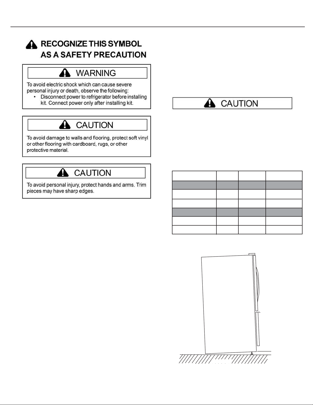
Listed below are the required height and width
dimensions for decorator panels. Panels are not
supplied with this kit but can be purchased locally.
To avoid personal injury or property damage, total
panel weight on single door should not exceed the
maximum weight; and the refrigerators front leg
levelers should be extended out to tilt the refrigerator towards its back and have an inclination of
6.35mm (1/4) from the floor.
Inportant
Read entire instructions before installing kit. Confirm all
parts listed are included in kit. If parts are missing, contact
source from whom kit was purchased. All parts in kit will
not be used in some installations.
· Mechanical experience is required to install kit.
· Depending on installers knowledge and skill, installation
can take from one to three hours.
· Transfer food to an alternate cooling source. Check
refrigerator warranty certificate for specific coverage.
Warranty does not cover food loss.
·If unable to solve a problem during installation, contact
source from whom kit was purchased.
6.35 (1/4) Panels
Refrigerator Door
Centimeters
Inches
Freezer Door
Centimeters
Inches
Height
d
106.8
(42 1/16)
d
59.61
(23 1/4)
Cabinet
Side view
Width
d
42.7
(16 13/16)
d
91.69
(36 1/8)
Max. Weight
d
6.8 kg.
15 lb.
d
7.70 kg.
17.00 lb.
1/4" (6.35 mm)
Floor
1
Page 3
Procedure
Tools Needed:
Phillips head screw driver
1/4" (6.35 mm) Hex socket
5/16" (7.9 mm) Hex socket
3/16" (4.8 mm) Drill bit
1/8" (3.2 mm) Drill bit
Pencil or marker
Rubber mallet
Tape measure
Drill
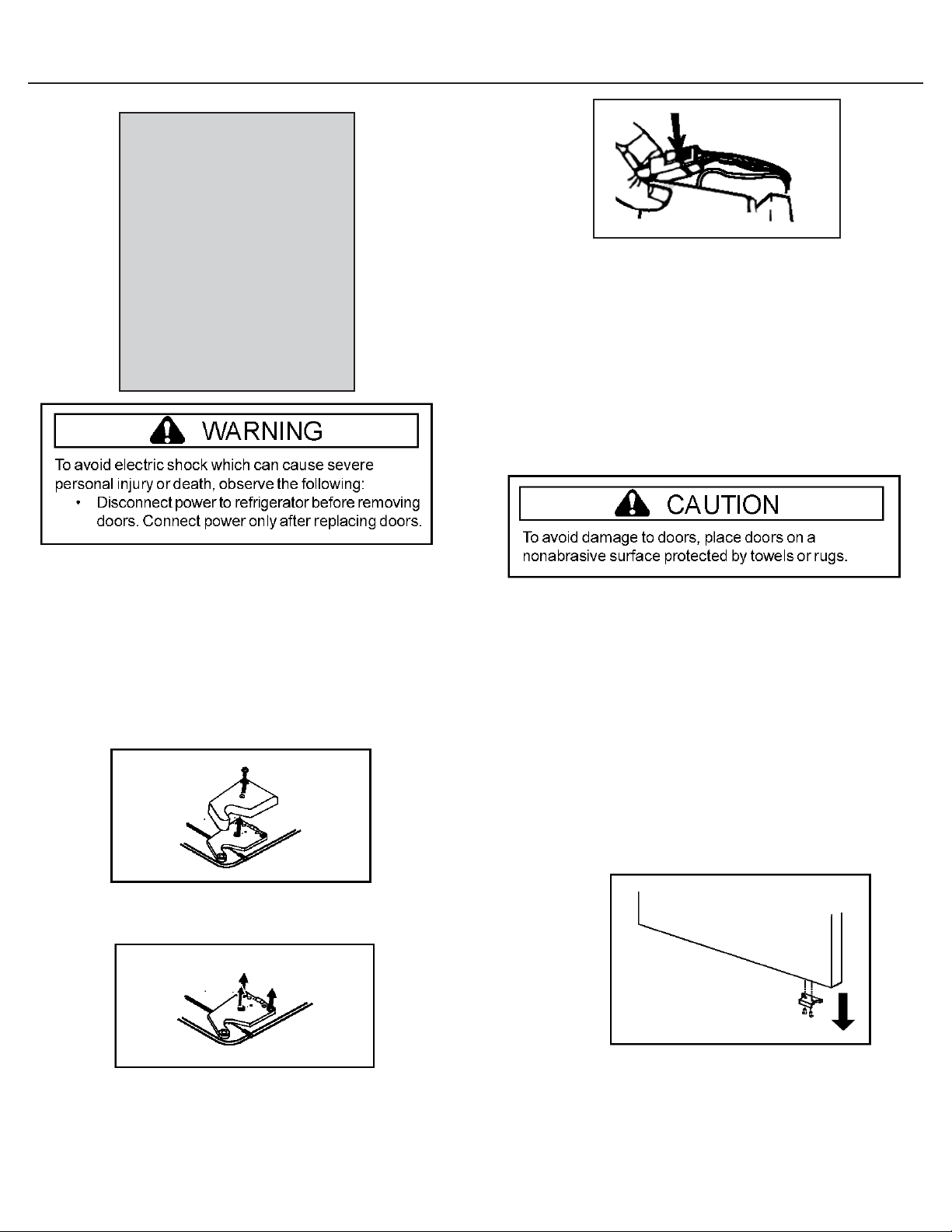
Figure 3
5. Lift refrigerator doors from bottom hinge pins.
6. Remove bottom hinges of refrigerator doors by
removing Phillips screws.
7. Replace with provided hinges and Phillips
screws that held previous hinges.
• These hinges will prevent doors from
swinging open too far and possibly
damaging trim panels.
Removing Refrigerator Doors and Hinges
1. Unplug power cord from power source.
2. Remove top hinge covers by removing Phillips
screws.
• Retain covers and screws for later
replacement. Figure 1
Figure 1
3. Remove top hinges by removing 5/16" (7.9 mm)
hex head screws. Figure 2
Figure 2
Installing Refrigerator Handles, Trim, and
Doors
1. Installing Bottom Trims on Refrigerator
Doors:
• Bottom trims should be installed on
refrigerator doors before side trims to
insure proper alignment.
• Remove existing door stop plates from
bottom of door that connect to bottom
hinges of refrigerator doors. Figure 4
4. Disconnect wire harness on top of left side
refrigerator door top hinge.Release two-pin
connector by pressing junction point with a flat
blade screwdriver or fingernail.Green ground
wire remains attached to the hinge. Figure 3
Figure 4
• Install bottom trims on bottom of
refrigerator doors using the Flat Top
Truss screws (quantity 14) making sure
that stop plates are reinstalled on the
outside of the bottom trims. Figure 5
2
Page 4

Note: The holes for the
left and right trims
will only line up
with the holes on
their corresponding
doors
2. Installing Refrigerator Side Trim:
• Ensure the U-shaped channel inside the
side trim is centered from top edge to bottom
edge in all four side trim pieces.
• Remove tape covering from the tape on
channel.
• Note: It is important to properly line up
trim before applying. Tape cannot be
removed from door and reused once it has
been applied.
• When looking down on the profile of the trim,
the back edge of the side trims are curled over
to form a J shape.
• The back edge of the side trims needs to be
flush with back edge of corresponding doors
and flush with bottom trims.
• Line up each refrigerator side trim piece with
corresponding door on refrigerator. Figure 6
Figure 5
• Install top trim on top of extensions on
both refrigerator doors using the Flat Top
Truss screws (quantity 14).
• Note: The holes for the left and right trims
will only line up with the holes on their
corresponding plastic extensions. Figure 7
Figure 7
4. Install refrigerator panels by sliding panels in
grooves on the handle side of door.
5. Replace refrigerator doors on their corresponding
bottom refrigerator hinges.
6. Replace top hinges on the doors by replacing 5/16"
(7.9 mm) hex head screws.
7. Replace top hinge covers on the doors by replacing
Phillips screws.
Figure 6
• Press trim firmly onto door.
• Slide side trim off and tap the U-
shaped channel with rubber mallet to
insure proper bond.
3. Installing Top Trim on Refrigerator Doors:
• Install plastic door extensions on top of both
refrigerator doors using the Slotted Hex
Washer Head screws (quantity 4).
8. Installing Fresh Food Door Handles:
• The door handles are reversible.
• Using provided hole location diagram, drill
into fresh food doors using 3/16" (4.8 mm)
and 1/8" (3.2 mm) drill bits.
• Note: Pointed end of clips face the front of
refrigerator and go into the 1/8" hole.
Figure 8
Figure 8
3
Page 5

• Screw door handle clips into holes with
1/4" (6.35 mm) Hex Washer Head screws
(quantity 6).
• The cut out notches on the door handle is
then lined up with the clips.
• Once the notches and clips are lined up,
push handle over the clips and slide
handle down until it locks into place.
• Tap on top of trim with rubber mallet to
insure snug fit.
4. Lift top of drawer to unhook door supports from rail
system and lift drawer out to remove. Figure 12
Figure 12
Removing Freezer Pullout Drawer
1. Pull drawer open to full extension. Remove Phillips
screw from each side of rail system. Figure 9
Figure 9
2. Remove lower basket by lifting basket from rail
system. Figure 10
Installing Freezer Handle and Pullout
Drawer Trim
1. Installing Bottom Trim on Freezer Drawer:
• Bottom trims should be installed on
freezer door before side trims to insure
proper alignment.
• Install bottom trim on bottom of freezer
door using the Flat Top Truss screws
(quantity 14).
• The holes for the trim will only line up
one way. Figure 13
Figure 10
3. Pull upper basket out to full extension and lift up to
remove. Figure 11
Figure 11
Figure 13
2. Installing Freezer Side Trim:
• Make sure that the U-shaped
channel is centered from top edge to
bottom edge in all four side trim
pieces.
• Remove tape covering from the tape
on the channel.
· Note: It is important to properly line
up trim before applying. Tape
cannot be removed from door and
reused once it has been applied.
4
Page 6

· When looking down on the profile of
the trim, the back edge of the side
trims are curled over to form a J
shape.
• The back edge of the side trims should
be flush with back edge of the drawer
and flush with bottom trim.
• Line up each freezer side trim piece with
door on freezer.
• Press trim firmly onto door.
• Slide side trim off and tap the U-
shaped channel with rubber mallet to
insure proper bond. Figure 14
Figure 15
Replacing Freezer Pullout Drawer
1. Pull both rails out to full extension. Figure 16
Figure 14
3. Install panel, sliding panel in grooves on top of
drawer.
4. Installing Freezer Handle:
• Place freezer handle on top of freezer
drawer.
• Align back of freezer handle with back
of freezer drawer and center handle
with the sides of the drawer.
• The ends of the freezer handle should
be flush with the side trim.
• Mark location of holes on freezer
drawer through holes on the handle.
• Remove handle and drill holes using a
1/8" (3.2 mm) drill bit.
• Replace handle on drawer and attach to
drawer using the Flat Phillips Head
screws (use the Flat Top Truss screws
for model HTKT05B). Figure 15
Figure 16
2. Hook door supports into rail tabs, as
illustrated and lower door into final position.
Figure 16
Figure 17
3. With drawer pulled out to full extension, insert
lower basket by aligning tabs on both sides of
lower basket with notches in rail assembly.
Figure 17
Figure 18
5
Page 7

4. Replace Phillips screw back into each side
of rail system.
5. Slide upper basket into unit. Make sure that
rear of basket hooks behind rail catch.
Figure 19
Figure 19
8.3 mm
[3 9/32]
REF
2.1 mm
[27/32]
19.05 mm
[3/4]
Scale 2.000
Detail 1
TYP
3 Places
0.5 mm
[3/16]
0.3 mm
[1/8]
SEE DETAIL 1
8.3 mm
[3 9/32]
47.1 mm
[18 9/16]
88.1 mm
47.1 mm
[18 9/16]
88.1 mm
[34 11/16]
8.3 mm
[3 9/32]
SEE DETAIL 1
6
Page 8

Part No. 12685913 © Printed in U.S.A. 02/05
7
 Loading...