

Page 1

Side-by Side
Refrigerator
1/4” Trim and Handle
Conversion Kits
Installation
Instructions
HTBK204
Part No. 12685910
Printed in U.S.A. 7/04
HK204
© Maytag Appliances Sales Co. 2004
Page 2
Important
Read entire instructions before installing kit. Confirm all
parts listed are included in kit. If parts are missing, contact
source from whom kit was purchased. All parts in kit will
not be used in some installations.
· Mechanical experience is required to install trim kit.
· Depending on installer’s knowledge and skill, installation
can take one to three hours.
· Transfer food to an alternate cooling source. Check
refrigerator warranty certificate for specific coverage.
Warranty does not cover food loss.
· Ensure trim pieces adhere properly by confirming door
surfaces are clean, dry and free of adhesive residue.
· If unable to solve a problem during installation, contact
source from whom kit was purchased.
Where to start
· If installing HK204 to replace a current handle,
proceed to the handle removal section
corresponding to your current handle. If installing
handles on new refrigerator complete step 3 on
page 4 then proceed to Installing New Handle
Section
· If installing HTBK204 proceed to Procedure section
on opposite page.
· When installing a HTBK204 kit a facade
replacement kit is necesary.
Facade Replacement Kits
In replacing facade refer to installation
instructions provided with facade kits.
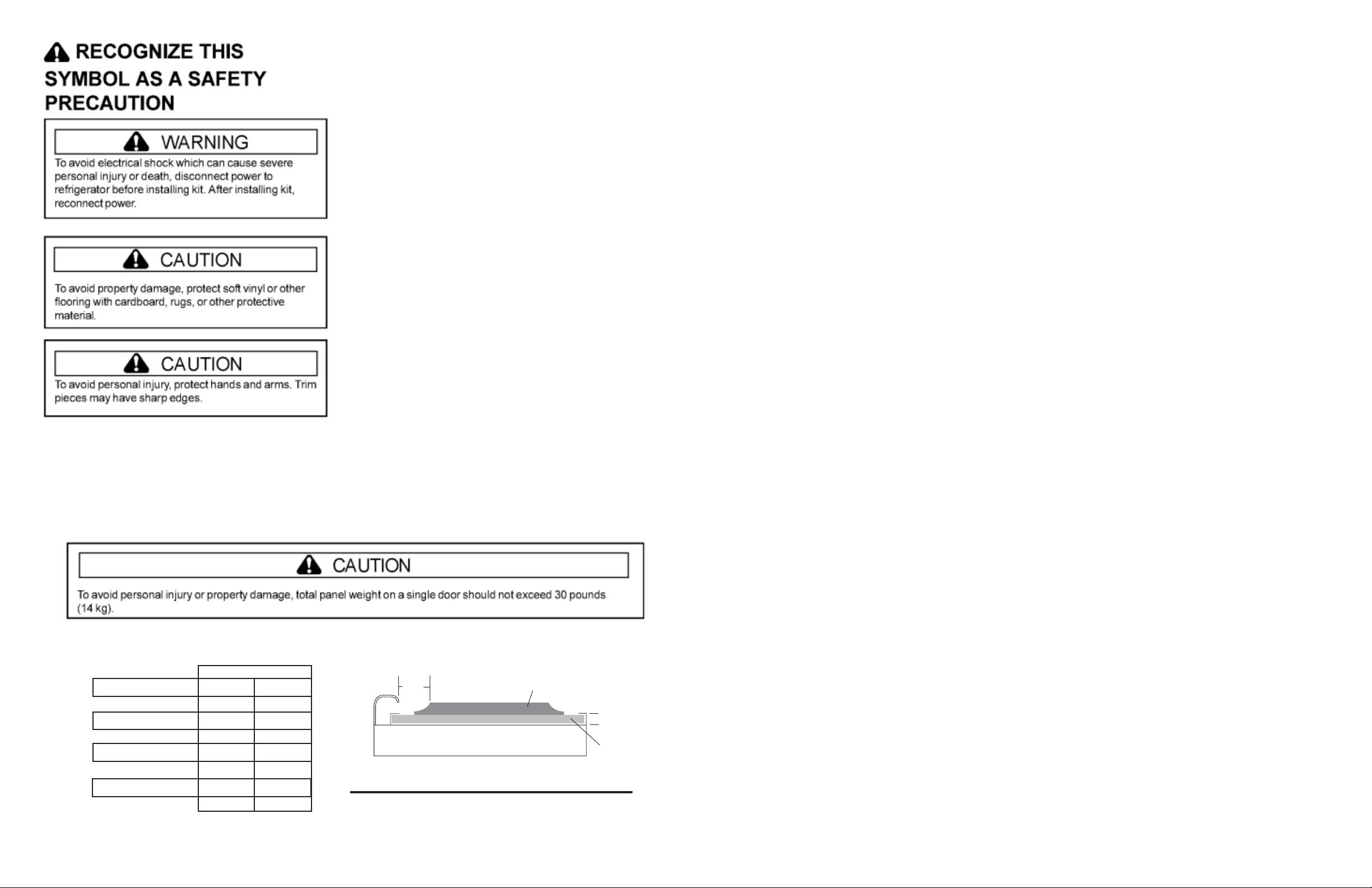
Decorator Panel Dimensions
Listed below are required height and width dimensions for decorator panels. Panels are not supplied with this kit but
can be purchased locally.
Typical Panel Installation
21/
2"
(6.3cm)
B
B. Backer Panel
D. Raised
D
1
(6mm)
/
4"
C
Refrigerator Door
I&W Door Upper
I&W Door Lower
Non/I&W Door
HTBK204
Panel Sizes
66 3/4 in 18 15/16 in
169.5 cm 48.1 cm
18 1/8 in 13 15/16 in
46.0 cm 35.4 cm
32 3/32 in 13 15/16 in
81.5 cm 35.4 cm
66 3/4 in 13 15/16 in
169.5 cm 35.4 cm
A. Handle
C. Door Panel
NOTE - Contact a cabinetmaker or
carpenter to create door panels
2
Page 3

Important
Permanent double-sided tape is used to attach side trim
pieces to refrigerator. Before moving paper backing,
check placement of all trim pieces on doors and inspect
panel positioning. Side trim pieces may be damaged if
adjustment or removal is attempted after side trim pieces
have been installed. (Following illustration shows side trim
orientation).
A. HTBK204 side trim
Side trim orientation
Install side door trim by peeling up 11/2” (38mm) of
4.
backing from bottom corner of side trim. Place trim
over outside end of bottom trim. For proper alignment,
side trim must be pulled tight against back of door.
After checking placement, peel off backing and press
into place. (Illustration shows top/bottom trim interface
with side trim.)
1545.67
[60 27/32]
402.11
[15 27/32]
1211.89
[47 23/32]
68.33
[2 11/16]
SEE DETAIL 1
Procedure
Removing Handles
To Remove: Bail type handle
1. If present, carefully pry handle trim away from door
panel.
2. Flex the handle away from the door panel.
Simultaneously place door handle removal card
underneath the base of the lower handle. Insert the
card to the line or until it stops.
3. Grasp the lower part of the handle firmly and lift to
remove.
1)
2)
CARD
CARD
3. To Disconnect the Water Line:
· Push in white collar (A) and hold.
· Pull the door side tube from the connector (B).
To Reconnect the Water Line:
· Firmly push tube 5/8” (15.7mm) into the
connector. Use lines on the tube as a guide for
full insertion.
· If the tube is damaged, cut off 5/8” (15.7mm)
before reconnecting.
4. Remove Screw and top hinge cover.
A. Top trim
C. Side trim
E. Bottom trim
Side trim placement
B. Freezer Door
D. Refrigerator Door
5. Tighten top trim screws.
68.33
[2 11/16]
REF
[13/16]
20.7
19.05
[3/4]
Detail 1
4 Places
Scale 2.000
TYP
[7/32]
2.4
[3/32]
5.5
4. Remove handle mounting hardware and metal
retainers from doors by removing screws.
To Remove: Extruded handle
1. Tap bottom edge of door handle upward with a
rubber mallet.
Removing Doors All Models
1. Use taped putty knife to pry toe grille off from top.
Pry off hinge covers from outer side of hinge cover.
Toe grille and hinge cover removal
2. Secure doors with masking tape to the cabinet.
A. Top hinge cover
Hinge cover removal
B. Top hinge screw
Unplug top hinge wire connectors before removing
top hinge.
A. Connector Lock
Disconnecting wire connectors
Unfasten top hinge from cabinet by removing top hinge
screws.
Removing door and top hinge
36
Page 4

5. Remove tape from freezer door. Grasp door
securely and lift up while opening. This will free
door from bottom hinge pin. Top hinge will
remain attached to door.
· Plastic water tube will slide through bottom
hinge pin as door is raised. (Dispenser
models only)
6. Remove tape from refrigerator door. Grasp
refrigerator door securely and lift up while
opening. This will free door from bottom hinge
pin. Top hinge may come off door.
7. Remove door stops by removing two screws
from each door.
Confirm plastic plug is removed
from the bottom of doors.
2. If necessary drill holes per diagram on page 6
for hole placement.
3. Install retaining clips (4 per door) for new fulllength handles. Insert tab at top of clip into hole in
door. Fasten clips to door with 1/4” hex head screw.
Facade Replace Kits
If replacing facade refer to installation instructions provided with facade kits.
Installing New Handles
Align notches on back of handle with retaining
clips on door to determine correct handle
orientation. Insert retainer clips in handle notches
and slide handle down until it contacts bottom
trim.
Extension should be pushed
against handle & flush with
side of door.
Use these holes as a guide
to drill holes in top of door.
Freezer door top view
Handle
A. Refrigerator/freezer door
C. Bottom door support plate
E. Door Stop
B. Plastic Plug
D. Bottom Trim
A. Tab of handle retainer fits in the hole in the door
B. Retainer clip
Retainer clip installation
C. Retainer screws
4. Dispenser Doors
Thread water tube through bottom hinge pin when
replacing freezer door. Tape doors to the cabinet with
masking tape. Replace top hinge screws. Reconnect
top hinge wire connectors. Carefully replace top
hinge cover to avoid pinching wires.
All Models
Set refrigerator and freezer door on bottom hinges.
Tape doors shut with masking tape. Replace
screws in top hinge, tighten screws. Place top
hinge cover on top of hinge. Insert and tighten screw
to fasten hinge cover.
A. Retainer clip
Handle installation
B. Handle Notch
Installing Trim & Panels - HTBK Kits
1. Place plastic extension on top of door
and if necessary drill 2.4mm (3/32) holes. Use
exsisting screw locations in plastic extension as
guide.
Attach door extension to tops of doors by inserting
1
and tightening
/4” hex head screws.
2. Install new top door trim by placing trim on top of
doors. Trim fits only one way. Insert top screws
(Phillips) removed earlier. Top trim screws should
be started but not tightened.
3. Slide decorator panels between top and bottom
door trim until panels are secure under door
handles.
E
D
Freezer Side
Plastic Extension
A
B
Reinstalling Doors See Fig 1.
1. Install support plate then bottom trim by placing
support plate and trim on bottom of doors. Insert
and tighten screws. Install door stop previously
removed on bottom of the doors. Insert and
tighten screw.
5. Dispenser Models
Reconnect water line, See Page #3
6. Attach covers for bottom hinges.
7. Replace toe grille.
Handle
Door
Freezer door side view (Handle Side)
Extension
C
A. Top Trim
C. Bottom Trim
E. Top Trim screws (Phillips)
Panel installation
B. Decorator panel
D. Extension screws
Important
Clean door surfaces of any residue to ensure that
trim adhesvie sticks properly.
54
 Loading...