

Page 1

NIA AG
Series Twelve
POWER VENT
GAS WATER HEATER
USER'SGUIDE
For Your Safety
AN ODORANTISADDEDTO THEGASUSEDBYTHISWATERHEATER Model Numbers
HN41240P
WARNING: If the information in these instructions are not fol- HN51240P
lowed exactly, a fire or explosion may result, causing property HP41240P
damage, personaliniury or death. HP51240P
HN41250P
-Do not store or use gasoline or other flammable vapors and liq- HN51250P
uidsinthe vicinity of this or any other appliance. HP41250P
-WHAT TO DOIFYOUSMELLGAS HP51250P
HN41250VZ
• Do not try to light any appliance. HN51250VZ
• Do not touch any electrical switch; do not use any phone in HN41275PZ
yourbuilding. HN51275PZ
• Immediately call your gas supplier from a neighbor's phone. HP41275PZ
Follow the gassupplier'sinstructions. HP51275PZ
• If you cannot reachyour gassupplier,call the fire department.
-Installation and servicemustbe performed bya qualified installer, FORPOTABLEWATER
serviceagencyor the gassupplier. HEATING ONLY
&WARNING NOT SUITABLEFOR
Improper installation, adjustment, alteration, service or mainte- SPACEHEATING
nance can cause DEATH, SERIOUSBODILY INJURY,OR PROPERTY
DAMAGE, Refer to this manual for assistanceor consult the local
gas utility for further information. NOT FOR USE IN
MANUFACTURED
AWARNING 1 (MOBILE) HOMES
Flammable vapors may be drawn by air currents from other
areas of the structure to this appliance.
Caution:
AWARNING I Read and Follow All
READ THE GENERAL SAFETY SECTION BEGINNING ON INSIDE I Safety Rules and
COVERAND THEN THIS ENTIREMANUAL BEFOREINSTALLING Operating Instructions
OR OPERATING THIS WATER HEATER, Before First Use of
Save this Manual for Future Reference. This Product.
Page 2

Safety Instructions
AWARNING AWARNING
Improl_er installation, adjustment, alteration, service At the time of manufacture this water heater was pro-
or maintenance can cause DEATH, SERIOUS BODILY vided with a combination temperature-pressures relief
INJURY,OR PROPERTYDAMAGE. Refer to this manu- valve certified by a nationally recognized testing labo-
al for assistance consult your local gas utility or call ratory that maintains periodic inspection of production
Maytag Customer Service at %800-788-8899 for an of listed equipment or materials, as meeting the
authorized servicer for further information, requirements for Relief Valves and Automatic Gas
Shutoff Devices for Hot Water Supply Systems, and
the latest edition of ANSI Z21.22 and the code require-
ments of ASME. If replaced, the valve must meet the
•,WARNING requirements of local codes, but not less than a combi-
WATER HEATERS EQUIPPED FOR ONE TYPE GAS nation temperature and pressure relief valve certified
ONLY: This water heater is equipped for one type as meeting the requirements for Relief Valves and
gas only. Check the model rating plate near the gas I Automatic Gas Shutoff Devices for Hot Water Supply
control valve for the correctgas. DO NOT USE THIS Systems, ANSI Z21.22 by a nationally recognized test-
WATER HEATER WITH ANY GAS OTHER THAN THE ing laboratory that maintains periodic inspection of
ONE SHOWN ON THE MODEL RATING PLATE.Failure production of listed equipment or materials.
to use the correct gas can cause problems which can I The valve must be marked with a maximum sat pres-
result in DEATH, SERIOUS BODILY INJURY, OR PROP- sure not to exceed the marked hydrostatic working
ERTY DAMAGE. If you have any questions or doubts pressure of the water heater (150 Ibs./sq. in.) and a
consult your gas supplier or local utility, discharge capacity not less than the water heater
input rate as shown on the model rating plate.
(Electric beaters - watts divided by 1000 x 3415 equal
BTU/Hr. rate.)
AWARNING Your local jurisdictional authority, while mandating the
INSTALLATIONS IN AREAS WHERE FLAMMABLE LIQ- use of a temperature-pressure relief valve complying
UIDS (VAPORS)ARE LIKELYTO BEPRESENTOR STORED with ANSI Z21.22 and ASME, may require a valve model
different from the one furnished with the water heater.
(GARAGES, STORAGE, AND UTILITY AREAS, ETC):
Flammable liquids (such as gasoline, solvents, propane Compliance with such local requirements must be sat-
(LP) or butane, etc.), all of which emit flammable isfied by the installer or end user of the water heater
vapors, may be improperly stored or used in such with a locally prescribed temperature-pressure relief
areas. The gas water heater ignitor or main burner can valve installed in the designated opening in the water
ignite suchvapors. The resulting flashback and fire can heater in place of the factory furnished valve.
causedeath or serious burns to anyone in the area, as Forsafe operation of the water heater, the relief valve
must not be removed from it's designated opening or
well as property damage.
If installation in such areas is your only option, then plugged.
the installation must be accomplished in a way that The temperature-pressure relief valve must be
the ignitor and main burner flame are elevatedfrom installed directly into the fitting of the water heater
the floor at least 18 inches. While this may reduce the designated for the relief valve. Position the valve
chances of flammable vapors from a floor spill being downward and provide tubing so that any discharge
ignited, gasoline and other flammable substances will exit only within 6 inches above, or at any distance
should never be stored or used in the same room or below the structural floor. Becertain that no contact is
area containing a gas water heater or other open made with any live electrical part. The discharge open-
flame or sparkproducing appliance, ing must not be blocked or reduced in size under any
NOTE: Flammable vapors may be drawn by air currents circumstances. Excessivelength, over 30 feet, or use of
from other areas of the structure to the appliance, more than four elbows can cause restriction and
reduce the discharge capacity of the valve.
No valve or other obstruction is to be placed between
the relief valve and the tank. Do not connect tubing
AWARNING
directly to discharge drain unlessa 6" air gap is provid-
IIf this water heat_ in beauty shops, ed. To prevent bodily injury, hazard to life, or property
]barber shops, cleaning establishments, or self-ser- damage, the relief valve must be allowed to discharge
Jvice laundries with dry cleaning equipment, it is water in quantities should circumstances demand. If
imperative that the water heater or water heaters the discharge pipe is not connected to a drain or other
be installed so that combustion and ventilation air suitable means, the water flow may cause property
be taken from outside these areas. Refer to the damage.
"Locating The New Water Heater" section of this The Discharge Pipe:
manual and also the latest edition of the National • Must not be smaller in size than the outlet pipe size
Fuel Gas Code, ANSI Z223.1, also referred to as NFPA of the valve, or have any reducing couplings or
54 for specifics provided concerning air required, other restrictions.
• Must not be plugged or blocked.
• Must be of material listed for hot water distribution,
AWARNING * Must be installed so as to allow complete drainage
of both the temperature-pressure relief valve, and
A fire can start if combustible materials such as the discharge pipe.
clothing, cleaning materials, or flammable liquids * Must terminate at an adequate drain.
are paced aga nst or next to the water heater. * Must not have any valve between the relief valve
and tank.
2
Page 3

Safety Instructions
_WARNING AWARNING
A gas water heater cannot operate properly without This water heater must not be installed directly on
the correct amount of air for combustion. Do not carpeting. Carpeting must be protected by a metal
install in a confined area such a closet, unless you or wood panel beneath the appliance extending
provide air as shown in the "Locating The New beyond the full width and depth of the appliance by
Water Heater" section. Never obstruct the flow of at least 3 inches (76.2mm) in any direction, or if the
ventilation air. If you have any doubts or questions appliance is installed in an alcove or closet, the
at all, call your gas company. Failure to provide the entire floor must be covered by the panel. Failure to
proper amount of combustion air can result in a fire heed th swarning may resu t in a f re hazard.
or explosion and can cause DEATH, SERIOUS BODILY
INJURY,OR PROPERTY DAMAGE,
AWARNING
The power vent water heater requires its own (sepa-
rate)venting system. It cannot be connected to an
•,WARNING existing vent pipe or chimney. It must be terminated I
HOTTER WATER CAN SCALD: Water heaters are to the outdoors. Failure to properly install the vent-
intended to produce hot water, Water heated to a ing system can result in asphyxiation, a fire or explo-
sion and can cause DEATH, SERIOUS BODILY INJURY
temperature which will satisfy clothes washing, dish
washing, and other sanitizing needs can scald and OR PROPERTYDAMAGE.
permanently injure you upon contact. Some people
are more likely to be permanently injured by hot
water than others. These include the elderly, children,
the infirm, or physically/mentally handicapped. If AWARNING
anyone using hot water m your home fits into one of
these. ¢_roupsor if there is a local code or state law No vent damper installation is compatible with this
power vented water heater design. No vent damper,
requiring a certain temperature water at the hot whether it is operated thermally or otherwise is to
water tap, then you must take special precautions. In be installed on this power vented water heater. AI-
addition to using the lowest possible temperature teration of any part of the factory-furnished vent as-
setting that satisfies your hot water needs, a means sembly could result in improper operation due to re-
such as a mixing valve, should be used at the hot striction of flue gases, spillage of flue gases and ma
water taps use(] by these people or at the water cause carbon monoxide poisoning.
heater. Mixing valves are available at plumbing sup-
ply or hardware stores. Follow manufacturers instruc-
tions for installation of the valves. Before changing
the factory setting on the thermostat, read the AWARNING
"Temperature Regulation" section in this manual.
The appliance and its individual shutoff valve must
be disconnected from the gas supply piping system
during any pressure testing of the gas system at
test pressures in excess of ½ pound per square inch
•,WARNING (3.5kPa).
Soot build-up indicates a problem that requires cot- The appliance must be isolated from the gas sup-
rection before further use. Turn "OFF" gas to water ply piping system by closing its individual manual
heater and leave "OFF" until repairs are made, shutoff valve during any pressure testing of the
gas supply piping system at test pressures equal or [
because failure to correct the cause of the sooting lessthan ½ pound per square inch (3.5kPa). I
can result in a fire or explosion causing DEATH, SERI-
OUS BODILYINJURY,OR PROPERTYDAMAGE.
AWARNING
AWARNING Chemical vapor corrosion of the flue and vent sys-
tem may occur if air for combustion contains certain
BEFORE LIGHTING [PROPANE (L.P.) GAS WATER chemical vapors. Spray can propellants, cleaning sol-
HEATERS]: Propane (L.P.) gas is heavier than air. I vents, refrigerator and air conditioner refrigerants,
Should there be a leak in the system, the gas will set- swimming pool chemicals, calcium and sodium chlo-
tie near the ground. Basements, crawl spaces, skirted ride, waxes, bleach, and process chemicals are typi-
areas under manufactured (mobile) homes (even cal compounds which are potentially corrosive.
when ventilated), closets and areas below ground
level will serve as pockets for the accumulation of
this gas. Before attempting to operate the water i
heater or turning on a nearby electrical light switch, J AWARNING J
be absolutely sure there is no accumulatecl gas in the
area. Search for odor of gas by sniffing at ground I Obstructed or deteriorated vent systems may pre-
Ilevel in the vicinity of the appliance. If odor is detect- I sent a serious health risk or asphyxiation.
ed, follow steps indicated at "For Your Safety" on the i
cover page of this manual then leave the premises, i 3 Safety Instructions continued on page 4.
Page 4

Safety Instructions
_WARNING 1 _,WARNING
Minimum clearances between the water heater and|" Vent termination" must not be within 4 feet of any
combustible or noncombustible construction are 0" at/ items such as gas meters, gas valves or other gas reg-
the sides and rear, 6" at the front, and 0" from the/ u atin_l equipment.
vent pipe. Clearance from the top of the jacket is 14"
on most models. Note that a lesserdimension may be
allowed on some models. Refer to the label on the I
water heater adjacent to tile gas control valve for all _ CAUTION
clearances, I WATER HEATERS EVENTUALLY LEAK: Installation of
the water heater must be accomp ished in such a
manner that if the tank or any connections should I
leak, the flow of water will not cause damage to
AWARNING the structure. For this reason, it is not advisable to
Flood damage to a water heater may not be readily install the water heater in at attic or upper floor,
visible or immediately detectible. However, over a When such locations cannot be avoided, a suitable
period of time a flooded water heater will create drain pan should be installed under the water
dangerous conditions which can cause DEATH, SERI- heater. Drain pans are available at your local hard-
OUS BODILY INJURY, OR PROPERTY DAMAGE.
ware store. Such a drain pan must be not greater I
Contact the Maytag dealer from whom the appli- than 1½ inches deep, have a minimum length and I
ance was purchased or call Maytag Customer Service width of at least 2 inches greater than the water
at 1-800-788-8899 for an authorized servicer to heater dimensions and must be piped to an ade-
replace a flooded water heater. Do not attempt to quate drain. The pan must not restrict combustion
repair the unit! It must be replaced! air flow. Under no circumstances is the manufactur-
er or Maytag to be held liable for any water dam-
age in connection with this water heater.
AWARNING
HYDROGEN GAS: Hydrogen gas can be produced in
a hot water system that has not been used for a
long period of time (generally two weeks or more).
Hydrogen gas is extremely flammable and explosive.
To prevent the possibility of injury under these con-
ditlons, we recommend the hot water faucet be
opened for several minutes at the kitchen sink
before any electrical appliances which are connected
to the hot water system are used (such as a dish-
washer or washing machine). If hydrogen gas is pre-
sent, there will probably be an unusual sound simi-
lar to air escaping through the pipe as the hot water
faucet is opened. There must be no smoking or open
flame near the faucet at the time it is open.
AWARNING I
INSULATING JACKETS: When installing an external I
water heater insulation jacket on a gas water heater:
• DO NOT cover the temperature-pressure relief valve.
• DO NOT put insulation over any part of the top of
the gaswater heater.
• DO NOT put insulation over the gas control valve or
gas control valve/burner cover, or any access areas
to the burner.
• DO NOT let insulation around the gas water heater
to get within 8 inches of the floor (air must get to
the burner).
• DO NOT cover or remove operating instructions,
and safety related warning labels and materials
affixed to the water heater.
Failure to heed this will result in the possibility of
fire or explosion.
4
Page 5

Table of Contents
Customer Information ........................................................................................................................6
_rc_cdeuctr_epeci_'_ti_ss_.eec_.ec_._____7
Accessories ........................................................................................................................................................................ .7
Basic Tools ...................................................................................................................................................................... .7
Instructions for Installation ..................................................................................................8-2s
Removing the Old Water Heater ...................................................................................................................................... 8
Typical Installation. .............................................................................................................................................................. .9
Locating the New Water Heater ................................................................................................................................. 10, 11
Combustion Air and Ventilation .................................................................................................................................... 11
Venting Clearances ....................................................................................................................................................... 11, 12
Combustion Air and Ventilation for Appfiances in Unconfined Spaces ............................................................................ 12
Combustion Air and Ventilation for Appliances in Confined Spaces ............................................................................ 13
Water Piping .................................................................................................................................................................... 14
Temperature-Pressure Relief Valve .................................................................................................................................. 15
Filling the Water Heater ................................................................................................................................................... 16
Wiring ...................................................................................................................................................................... 16, 17
Venting ..................................................................................................................................................................... 18-26
Gas Piping ............................................................................................................................................................. .26, 27
Installation Checklist ...................................................................................................................................................... 28
Instructions for Operation ....................................................................................................... 29-32
Operating ............................................................................................................................................................... .2%31
Temperature Regulation ................................................................................................................................................ 32
Service and Maintenance ............................................................................................... 33-35
Venting System Inspection. .............................................................................................................................................. 33
Oiling Instructions ............................................................................................................................................................ 33
Burner Inspection ........................................................................................................................................................... .33
Burner Cleaning. ........................................................................................................................................................... .33
L.P. Gas Control Valve and Burner Assembly Replacement Information .......................................................................... 34
Draining ........................................................................................................................................................................ 34
Temperature-Pressure Relief Valve Operation ................................................................................................................. 35
Drain Valve Washer Replacement ................................................................................................................................. .35
Housekeeping ................................................................................................................................................................ 35
Service ......................................................................................................................................................................... .35
Troubleshooting ....................................................................................................................................... 36-43
Start Up Conditions ....................................................................................................................................................... 36
Condensation .............................................................................................................................................................. 36
Smoke/Odor ................................................................................................................................................................. .36
Thermal Expansion ..................................................................................................................................................... 36
Strange Sounds ........................................................................................................................................................... 36
Operational Conditions ............................................................................................................................................. 37, 38
Smelly Water ............................................................................................................................................................. 37
"Air" in Hot Water Faucets ....................................................................................................................................... 37
High Temperature Shut Off System ........................................................................................................................... .37
Venting Manual Reset Switch ....................................................................................................................................... 37
Not Enough Hot Water .............................................................................................................................................. 38
Water is too Hot .......................................................................................................................................................... 38
Leakage Checkpoints ................................................................................................................................................. .39
Thermostat and Gas Supply Check ......................................................................................................................... .40
Electrical System Check ...................................................................................................................................... A1-43
Repair Parts List ......................................................................................................................... 44-52
Warranty ...........................................................................................................................................................56
5
Page 6

Customer Information
Thank Youfor purchasing a Maytag water heater, the first few pages, READ THE ENTIRE MANUAL
BEFORE ATTEMPTING TO INSTALL OR OPER-
Properly installed and maintained, it should give you years of ATE THE WATER HEATER.
trouble flee service. It is strongly suggested that thls new water • The instaUation must conform with the instructions in this
heater be professionally installed, contact Maytag Customer
Service (1-800-788-8899) for recommended installers, manual; gas company rules; and Local Codes, or in the
absence of Local Codes, with the latest edition of the
Abbreviations Found In This Instruction Manual National Fuel Gas code, ANSI Z223.1, also referred to as
CSA - Canadian Standards Association NPPA 54. This publication is available from your local
NFPA - National Fire Protection Association government or public fibrary or gas company or by writing
ANSI - American National Standards Institute NFPA, Batterymarch Park, Quincy, MA 02269.
After reading this manual you have any questions or do not
A WARNING understand any portion of the instructions, call Maytag
This gas-fired water heater is design certified by Customer Service at 1-800-788-8899 for an authorized
CSA INTERNATIONAL under American National servicer.
Standard/CSA Standard for Gas Water Heaters ANS
Z21.10.1 • CSA 4.1 (latest edition). The installation Carefiflly plan the place where you are going to put the
must conform with this manual, Local Codes and water heater. Correct combustion, vent action, and vent
with the latest edition of the National Fuel Gas pipe installation are very important in preventing death
Code, ANSI Z223.1. from possible carbon monoxide poisoning and fires.
This publication is available from your local govern-
ment or public library, gas company, or by writing Examine the location to ensure the water heater complies
NFPA, Batterymarch Park, Quincy, MA 02269. with the "Locating the New Water Heater" section in this
manual
• Read the "Safety Instructions" section, pages 2, 3 and 4 of
For California installation this water heater must be braced,
this manual first and then the entire manual carefillly. If anchored, or strapped to avoid £alfingor moving during an
you don't follow the safety rules, the water heater will not
earthquake. See instructions for correct installation proce-
operate properly. It could cause DEATH, SERIOUS
dures. Instructions may be obtained from your local dealer,
BODILY INJURY AND/OR PROPERTY DAMAGE. wholesaler, public utilities or California Office of the State
This manual contains instructions for the installation, Architect, 400 P Street, Sacramento, CA 95814,
operation, and maintenance of the gas-fired water heater. Massachusetts Code requires this water heater to be
It also contains warnings through out the manual that you installed in accordance with Massachusetts 248-CMR 2.00:
must read and be aware o£ All warnings and all instruc- State Plumbing Code and 248-CMR 5.00.
tions ate essential to the proper operation of the water Compiles with SCAQ_MD rule #1121 and districts having
heater and your safety. Since we cannot put everything on equivalent NOx requirements.
Product Specifications
Model HN41240P HP41240P HN41250P HP41250P IHN41250VZ HN41275PZ I HP41275PZ
l I
•HN51240P *HP51240P *HN51250P *HP51250P *HN51250VZ *HNS1275PZ *HPS1275PZ
Tank Capacity
In Gallons 40 40 50 50 50 75 75
Type of Gas Natural Propane Natural Propane Natural NaturM Propane
B.T.U. rate 40,000 40,000 40,000 40,000 52,500 75,000 70,000
Recovery Rate
In Gals Per Hr.
@90*FRise 46.0 46.0 46.0 46.0 57.0 77.0 72.0
Vent Pipe 3" ** 3" ** 3" ** 3" ** 3" *** 3" *** 3" ***
Diameter 20" 20" 22" 22" 22" 26%" 26Vf"
Height To
Top of Blower 71%" 71%" 71%" 71%" 68V_" 71%" 71Vf'
• High altitude models have a B.T.UJRecovery Rate 10% less than shown.
•*Limited usage ofT' vent pipe - see pages 19 through 26.
•**Limited usage of 4" vent pipe - see pages 19 through 26.
6
Page 7

Accessoriesand ToolsNeeded
Accessories
To simplify the installation Maytag has available the installa-
tion parts shown below. You may or may not need all of these
accessories depending on your type of installation. Call
Maytag Customer Service at 1-800-788-8899 for an autho-
rized installer.
DRAINPANSAVAILABLEIN 22" DIAMETER
(PARTNUMBER66001011)FORWATER
HEATERSHAVINGA DIAMETER20_ORLESS,
24' DIAMETER(PARTNUMBER66001105) FOR
EXPANSIONTANKSFORTHERMALEXPANSION WATERHEATERSHAVINGA DIAMETER22"
CONDITIONSAVAILABLEIN 2 GALLON(PART OR LESSAND AVAILABLEIN 28" DIAMETER
NUMBER66001013) AND 5 GALLON(PART (PARTNUMBER66001012)FORWATER
NUMBER66001014) CAPACITY HEATERSHAVINGA DIAMETER26" ORLESS
Tools
You may or may not need all of these tools, depending on your ADDITIONAL TOOLS NEEDED
type of installation. These tools can be purchased at your local WHEN SWEAT SOLDERING
hardware store.
• Tubing Cutters or Hacksaw
• Propane Torch
• Pipe Wrenches (2) 14" • Soft Solder
• Screwdriver • Solder Flux
• TinSnips _ I _ .EmeryCIoth
• 6 Foot Tape of Folding Rule • Wire Brushes
• Garden Hose
• Drill
• Pipe dope or Teflon Tape GARDENHOSE
HACKSAW
PPE6 FOOTTAPE WRENCH _
ROLLOF TEFLONTAPE 314"WIREBRUSH
(USEONLYON WATER
CONNECTIONS)
1/2" WIREBRUSH
_ _ PROPANETORCHSLOTHEADSCREWDRIVER
TIN SNIPS
PHILLIPSSCREWDRIVER ROLLOF LEADFREE
SOFTSOLDER
PIPEDOPE(SQUEEZETUBE) ROLLOFEMERY
(USEFORWATERAND _ _qw_ CLOTH SOLDERFLUX TUBINGCUTFER
GASCONNECTIONS) _ _
7
Page 8

Instructions for Installation
Removing the Old Water Heater
Turn "OFF" the supply to the water heater. ('_ Disconnect the vent pipe from the draft hood where they
gas
connect to the water heater. In most installations the vent
] pipe can be rifted offafter any screw or other attached
if the main gas hoe'sh_gas_'WARNING ap#iances is used, ]| devices are removed. Dispose of the draft hood. The new
alsoshut"off" the gasat each appliance.Leaveallgasappli-/ water heater has the draft hood which must be used for
ancesshut"off" untilthe water heaterinstallationiscomplete. J proper operation.
a. If you have copper piping to the water
heater, the two copper water pipes can
o
I four inches away from where they con-
nect to the water heater. This will
_'_- avoid cutting offthe pipes too short.
@__ Additional cuts can be made later if
necessary. Disconnect the temperature-
pressure relief valve drain fine. When
QTurn "OFF" the water to the water _ the water heater is drained, disconnect
the hose from the drain valve. Close
heater. Some installations
require
that
{_ the drain valve. The water heater is
the water be turned off to the entire
house. @ _ readyn°WcompletelYtobe removed.disc°nnectedand
,
make the
Check again to sure gas sup-
ply is "OFF" to the water heater. Then I _ B_a Q b. If you have galvanized pipe to the water
disconnect the gas supply connection _L_) heater, loosen the two galvanized pipes
from the gas control valve, with a pipe wrench at the union in each
t fine. Also disconnect the piping
t remaining to the water heater. These
Attach pieces should be saved since they may
hosea to the wa[3erheater drain
valve and put the other end in a floor
drain or outdoors. Open the water _ _-" _ be needed when reconnecting the new
water heater. Disconnect the tempera-
heater drain valve. Open a nearby hot ture-pressure relief valve drain line.
water faucet which will relieve pressure When the water heater is drained, dis-
in the water heater and speed draining, connect the hose from the drain valve,
Close the drain valve. The water heater
__ ._ is now completely disconnected and
ready to be removed.
_,WARNING ACAUTION
Thewater passingoutof thedrainvalvemaybeextremelyhot, Mineralbuildupor sedimentmay haveaccumulatedinthe old
Toavoidbeingscalded,makesureall connectionsare tightand water heater.Thiscausesthe waterheaterto be muchheavier
thatthe waterflow isdirectedawayfromanyperson, thannormalandthisresidue,ifspilledout, couldcausestaining.
8
Page 9

Instructions for Installation (cont'd)
Typical Installation
VENT TO
OUTDOORS
VacuumReliefrequired
some codes
codes)
COLD WATER INLET
HOT WATER OUTLE1
t
TEMPERATURE-
PRESSURE
TEMPERED
WATER OUTLET MIXING ( S (Do not cap or plug)
VALVE SL _LY PROVIDE A 6_AIR GAP
BETWEEN THE END OF
THEDISCHARGEPIPE
i AND DRAIN
7' POWER CORD
(Factory supplied) O
This appliance has been design certified as complying with American National Standard/CSA Standard for water heaters and is
considered anitable for:
Water (Potable) Heating: A11models are "considered suitable for water (potab]e) heating."
AWARNING AWARNING J
When the system requires water at temperatures This water heater shall not be connected to any heat-
higher than required for other uses, the hot water ing systems or component(s) previously used with a I
system may require a means such as a mixing valve non-potable water heating appliance. I
to be installed to temper the water at certain
points of use. Somepeople are more likely to be AWARNING
permanently injuredby hot water than others;
these include the elderly, children, the infirm, or Toxic chemicals such as used for treatment of boil- I
the physically/mentally handicapped. Before ers or non-potable water heating appliances shall I
immersing yourself or anyone else in hot water, be never be introduced into a potable water space
sure to check the water temperature. WARNING: heating system.
HOTTER WATER INCREASES THE RISK OF SCALD
INJURY. (Also see "Temperature Regulation" sec-
tion) Mixing valves are available at plumbing sup- NOTE: To protect against untimely corrosion of hot and cold
ply or hardware stores. Follow manufacturers water fittings, it is strongly recommended that di-electric
instructions for installation of these valves, unions or couplings be installed on this water heater when
connected to copper pipe.
9
Page 10

Instructions for Installation (cont'd)
Locating the New Water
Heater
Youshould carefiallychoose an indoor location for the new water A WARNING
heater, because the placement is a very important consideration
for the safetyof the occupants in the building and for the most DO not use an extension cord. If there is not a suit-
economical use of the appliance. Thiswaterheateris not foruse able receptacle and/or local codes prohibit use of a
in manufactured (mobile)homes oroutdoor installation, power cord, f e d wiring must be prov ded.
Whether replacing an old water heater or putting the water heater
in a new location, the following critical points must be observed. A CAUTION
WATER HEATERS EVENTUALLY LEAK: Installation of
• The location selected should be indoors asclose as practical to the water heater must be accomplished in such a
the vent termination point, and ascentralized with the water manner that if the tank or any connections should
piping system as possible. The water heater, as all water leak, the flow of water will not cause damage to
heaters, will eventually leak. Do not install without adequate the structure. For this reason, it is not advisable to
drainage provisions where water flow will cause damage, install the water heater in an attic or upper floor.
When such locations cannot be avoided, a suitable
• 40,000 BTU/HRINPUTMODELS- If vented through an drain pan should be installed under the water
outside wall or through the roof, the 3" vent piping cannot heater. Drain pans are available at your local hard-
exceed a total of 115 feet (50 feet ifoptional 2"vent piping is ware store. Such a drain pan must be not greater
used), including vertical and horizontal runs with one 90° than 1½ inches deep, have a minimum length and
elbow.If more elbows are required, the venting distance must width of at least 2 inches greater than the water
be reduced 5 feet for every 90° elbow. See page 21 forvent heater dimensions and must be piped to an ade-
chart, quate drain. The pan must not restrict combustion
air flow. Under no circumstances is the manufactur-
• 52,500, 70,000 AND 75,000 BTU/HR INPUT MODELS-If er or Maytag to be held liable for any water dam-
vented through an outside wall or through the roof, the 3" vent age in connection with this water heater.
piping cannot exceed a total of 70 feet (110 feet if optional 4"
vent piping is used), including vertical and horizontal runs with
one 90° elbow. If more elbows are required, the venting distance • The location selection must provide adequate cleararlces for
must be reduced 5 feet for every 90°elbow. See page 21 for servicing and proper operation of the water heater.
vent chart.
• Vent piping cannot slope downward and horizontal runs AWARNING
require %"per five foot rise.All horizontal runs require ade- INSTALLATIONSIN AREAS WHERE FLAMMABLE LIQ-
quate support at 3 1/2foot intervals and verticalruns supported UIDS (VAPORS) ARE LIKELY TO BE PRESENT OR
at 5 foot intervals. STORED (GARAGES, STORAGE, AND UTILITY AREAS,
ETC): Flammable liquids (such as gasoline, solvents,
• The water heater requires its own (separate)venting system. It propane (LP) or butane, etc.), all of which emit
cannot be connected to an existing vent pipe or chimney. It flammable vapors, may be improperly stored or
must terminate to the outdoors. Whenever possible terminate used in such areas. The gas water heater ignitor or
the vent on the leeward sideof the building ifvented through main burner can ignite such vapors. The resulting
an outside wall. NOTE: Condensation maybe created, at flashback and fire can cause death or serious burns
times, as the combustion gases exit the vent cap and discol- to anyone in the area, as well as property damage.
orationofsurfacesinproximitytotheventcapmayoccur. If installation in such areas is your only option,
then the installation must be accomplished in a
way that the ignitor and main burner flame are ele-
vated from the floor at least 18 inches. While this
AWARNING may reduce the chances of flammable vapors from
The power vent water heater requires its own (sepa- a floor spill being ignited, gasoline and other
rate) venting system. It cannot be connected to an ex- flammable substances should never be stored or
isting vent pipe or chimney. It must be terminated to used in the same room or area containing agas
the outdoors. Failureto properly install the venting sys- water heater or other open flame or spark produc-
tem can result in asphyxiation, a fire or explosion and ing appliance.
cancause DEATH,SERIOUSBODILYINJURY,OR PROPER- NOTE:Flammable vapors may be drawn by air currents
TY DAMAGE. from other areasof the structure to the appliance.
AWARNING
• The water heater comes equipped with a 7 foot power cord Propellants of aerosol sprays and volatile com-
which can be used to connect to a 110/120 volt power pounds, (cleaners, chlorine based chemicals, refrig-
source if(l) local codes allow, and (2) there is a three prong erants, etc.) in addition to being highly flammable
receptacle available. This unit must have a grounded out- in many cases, will also change to corrosive
let to operate, hydrochloric acid when exposed to the combustion
products of the water heater. The results can be
hazardous, and also cause product failure,
10
Page 11

Instructions for Installation (cont'd)
Locating the New Water Combustion Air and Ventilation
Heater (cont'd) When determining the installation location for a power vent
water heater, snow accumulation and drifting should be con-
AWARNING sidered in areas where applicable.
This water heater must not be installed directly on
carpeting. Carpeting must be protected by a metal VENTING CLEARANCES
or wood panel beneath the appliance extending
beyond the full width and depth of the appliance • 0" clearancefor 3" (andopfionzl 2" and4") PVC, ABS or
by at least 3 inches (76.2mm) in any direction, or if CPVC Schedule40vent piping from combustiblesurfaces.
the appliance is installed in an alcove or closet, the
entire floor must be covered by the panel. Failure • 12" minimum from the ground,9" ceilingoverhangs.
to heed this warning may result in a fire hazard. Figure 2.
• The Power Vent outlet terminal shall terminate at least 36"
above any forced air inlet into the building located within 10
A WARNING feet. Figure 3a.
Minimum clearances between the water heater and
combustible or noncombustible construction are 0" • The Power Vent outlet terminal shall terminate atleast 4 feet
at the sides and rear, 6" at the front, and O" from below, 4 feet horizontally from or 1foot above any door, window
the vent pipe. Clearance from the top of the jacket or gravity air inlet into the building. Figure 3a.
is 14" on most models. Note that a lesser dimension
may be allowed on some models. Refer to the label • 18" minimum from other natural draft (gravity) direct vent,
on the water heater adjacent to the gas control power vent or power direct vent appliance inlet and/or outlet
valve for all clearances, vent(s) when directly aboveor 135°to either side of center
line. Figure 3b.
_ • 24" minimum from any appfiance inlet and/or outlet vents"
VENTILATION
/ A,. ,J u = , ,i/i _ = _M,N. • 18° minimum in all directions from any obstruction that may
/ OPENINGS_JI 0" MIN.
TOP VIEW , I
[ _ I OF CLOSET TOPVIEW 0 HIN. interfere. Figure 3c.
|_'_.,_ | _NIT_OLE DOOR OF CLOSET
/ 1_2"H_X, WITH DOOR
__ • The location selection must provide clearances for servicing
FRONTVIEW _ _"IN
OFDOOR . and proper operation of the water heater. Figure 4.
Figure 1 / A,_OUCT * Vent termination must not be within 4 feet of any items such]
as gas meters, gas valves orother gas regulating equipment.
A WARNING • The venting system must be installed in a manner which
allows inspection oftlie installation of the venting pipes and
A gas water heater cannot operate properly with- joints as well as periodic inspection after installation as
out the correct amount of air for combustion. Do
not install in a confined area such a closet, unless required byANSI Standards.
you provide air as shown in the "Facts to Consider
About the Location" section. Never obstruct the
flow of ventilation air, If you have any doubts or , AWARNING
questions at all, call your gas company. Failure to
provide the proper amount of combustion air can Vent termination must not be within 4 feet of any
items suchas gas meters, gas valves or other gas reg-
result in a fire or explosion and can cause DEATH, u ating equ pment.SERIOUS BODILY INJURY, OR PROPERTY
DAMAGE.
AWARNING
AWARNING Failure to have required clearances between water
heater and combustible material will result in a fire
If this water heater will be used in beauty shops, hazard.
barber shops, cleaning establishments, or self-ser-
vice aundr es w th dry clean ng equ pment, it s
imperative that the water heater or water heaters
be installed so that combustion and ventilation air
be taken from outside these areas. Refer to the
"Facts to Consider About the Location" section of
this manual and also the latest edition of the
National Fuel Gas Code, ANSI Z223.1, also referred
to as NFPA 54 for specifics provided concerning air
required.
11
Page 12

Instructions for Installation (cont'd)
Mustmaintain
adequateservice /- .......... "--..
andmaintenance // ",
any9"min.overhangfrOm accessibility._ _: ",,,
otF,oe
12"rnin. Fgure 4 ' Rankleof degrees
I I "" ,/ availablefor vent
""_............."" pipe installation.I
i Venting Through Roof- ClearancesI I • 0" clearance for 3" (or optional 2" and 4") PVC, ABS, or
Figure 2 , _ CPVC Schedule 40 piping from combustible surfaces.
m
inches above the roof surface. Figure 5.
"- • The location selection must provide clearances for servicing
and proper operation of the water heater. Figure 4.
• The venting system must be installed in a manner which
allows inspection of the installation of the venting pipes and
IFLESSTHAN joints as well asperiodic inspection after installation as
48" _ k_L-.,_,-_.,,_ required by AN SI Standards.
w,.REE./ '°°"EE'ELL
TP-EOR_ERVENTI FigUF" 3¢_IIiUmin" __,_ FO_NC_DALR_LET _'r' _:_
POWERVENTTERMINAL_ _-
- " -- '\ - _NATURALDRAFT(GRAVITY)
O,RE VENT.POWERVE.T.CombustionAir and Ventilation
ORPOWERO,RE VE T for AppliancesLocatedin_-=- APPLIANCEINLETAND/OR
\_ -- OUTLETVENT(S), Confined Spaces
IFigure 3111 Unconfined Space is a space whose volume is not less than
50 cubic feet per 1,000 Btu per hour of the aggregate input
rating of all appliances installed in that space. Rooms com-
municating directly with the space in which the appliances are
ventterminal 18"to wallorother
obstructionsthatmay installed, through openings not furnished with doors, are
interfere with venting.
considered a part of the unconfined space
I_ 18"rnin._
In unconfined spaces in buildings, infiltration may be ade-
quate to provide air for combustion, ventilation and dilution
_ /_ ventterminal of flue gases. However, in buildings of tight construction (for
1 example, weather stripping, heavily insulated, caulked, vaporFigure3Cj m" .
cornerofbuildina barrier, etc.), additional air may need to be provided using the
methods described in Combustion Air and Ventilation for
Appliances Located in Confined Spaces, b.
12
Page 13

Instructions for Installation (cont'd)
Combustion Air and Ventilation 1.Whendirectlycommunicatingwiththeoutdoors,each
for
opening shall have a minimum free area of 1 square inch
Locatedin per 4,000 BTU per hour of total input rating of all equip
Confined Spaces(cont'd) merit in the enclosure. (See Figure 7.)
Confined Space is a space whose volume is less than 50 cubic 2. When communicating with the outdoors through vertical
feet per 1,000 Btu per hour of the aggregate input rating of all ducts, each opening shall have a minimum free area of 1
appliances installed in that space, square inch per 4,000 BTU per hour of total input rating of
a. ALL AIR FROM INSIDE BUILDINGS: all equipment in the enclosure. (See Figure 8.)
(See Page 11 Figure 1, and Figure 6 below) (each endofattic)
The confined space shall be provided with two permanent
openings communicating directly with an additional
room(s) of sufficient volume so that the combined volume
, VENT TO
of all spaces meets the criteria for an unconfined space.
The total input of all gas utilization equipment installed in
the combined space shall be considered in making this
r 3
determination. Each
opening shall have a minimum free [ Figure 8 ]
area of one square inch per 1,000 BTU per hour of the
total input rating of all gas utilization equipment in the 3. When communicating with the outdoors through horizon-
confined space, but not less than 100 square inches. One tal ducts, each opening shall have a minimum free area of 1
opening shall commence within 12 inches of the top and square inch per 2,000 BTU per hour of total input rating of
one commencing within 12 inches of the bottom of the all equipment in the enclosure. (See Figure 9.)
enclosure.
_ ROOF
VENT THROUGH j
_ ROOF
m
i 1 o oooRsI I
OPENINGS WATER Figure 9
- HEATER
[igu,e ] "H
4. When ducts are used, they shall be of the same cross-sec-
tional area as the free area of the openings to which they
connect. The minimum short side dimension of rectangular
b. ALL AIR FROM OUTDOORS: (see Figures 7-9) air ducts shall not be less than 3 inches. (See Figure 9.)
The confined space shall be provided with two permanent 5. Louvers and Grilles: In calculating free area, consideration
openings, one commencing within 12 inches of the top shall be given to the blocking effect of louvers, grilles or
and one commencing within 12 inches from the bottom of screens protecting openings. Screens used shall not be
the enclosure. The openings shall communicate directly, or smaller than 1/4inch mesh. If the free area through a design
by ducts, with the outdoors or spaces (crawl or attic) that
of louver or grille is known, it should be used in calculating
freely communicate with the outdoors, the size opening required to provide the free area specified.
If the design and free area is not known, it maybe assumed
(eachendofattic) that wood louvers will be 20-25 percent free area and metal
louvers and grilles will have 60-75 percent free area.
Louvers and grilles shall be fixed in the open position or
interlocked with the equipment so that they are opened
automatically during equipment operation.
6. Special Conditions Created byMechanical Exhausting or
Fireplaces: Operation of exhaust fans, ventilation systems,
E
clothes dryers or fireplaces may create conditions requiring
Figure I special attention to avoid unsatisfactory operation of
7
VENTiLATiONLOUVERS installed gas utilization equipment.
13
Page 14
Instructions for Installation (cont'd)
Water Piping
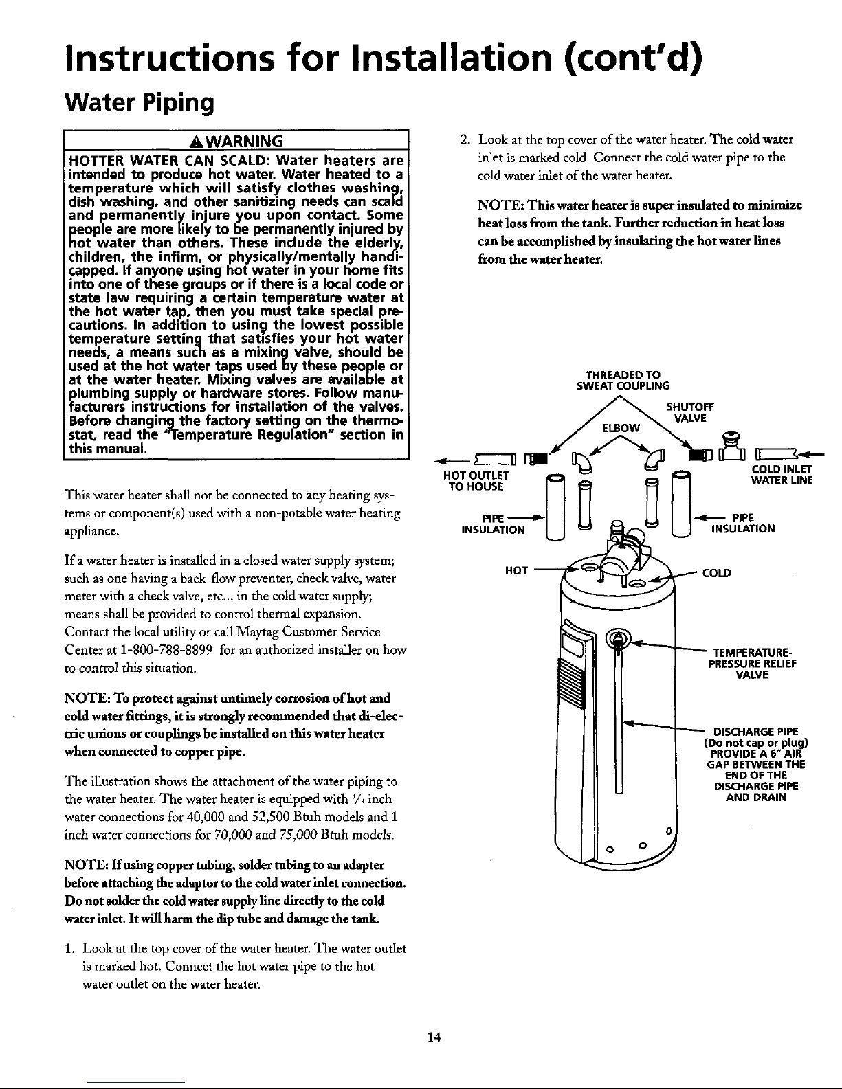
A,WARNING 2. Look at the top cover of the water heater. The cold water
HOTTER WATER CAN SCALD: Water heaters are inlet is marked cold. Connect the cold water pipe to the
intended to produce hot water. Water heated to a coldwater inlet of the water heater.
temperature which will satisfy clothes washing,
dish washing, and other sanitizing needs can scald NOTE: This water heater is super insulated to minimize
and permanently injure you upon contact. Some
people are more likely to be permanently injured by heat loss from the tank. Further reduction in heat loss
hot water than others. These include the elderly, can be accomplished by insulating the hot water llnes
children, the infirm, or physically/mentally handi- from the water heater.
capped. If anyone using hot water in your home fits
into one of these groups or if there is a local code or
state law requiring a certain temperature water at
the hot water tap, then you must take special pre-
cautions. In addition to using the lowest possible
temperature settingthat satisfies your hot water
needs, a means such as a mixing valve, should be
used at the hot water taps used by these people or
at the water heater, Mixing valves are available at THREADEDTO
SWEAT COUPLING
plumbing supply or hardware stores. Follow manu-
tacturers instructions for installation of the valves. _ SHUTOFF
Before changing the factory setting on the thermo- /[ E_._]3 _
stat, read the '_remperature Regulation" section in
this manual. • _ [1 I I1 _,-_
COLD INLET
HOT OUTLET _ _ _ _1 WATER LINE
This water heater shall not be connected to any heating sys- TOHOUSE [ [
tems or component(s) used with a non-potable water heating PIPE _ U II PIPE
appliance. INSULATION INSULATION
If a water heater is installed in a closed water supply system;
such as one having a back-flow preventer, check valve, water HOT _-_ COLD
meter with a check valve, etc.., in the cold water supply;
means shall be provided to control thermal expansion,
Contact the local utility or call Maytag Customer Service _ _ _ TEMPERATURE-
Center at 1-800-788-8899 for an authorized installer on how
to control this situation. PRESSURERELIEF
VALVE
NOTE: To protect against untimely corrosion of hot and
cold water fittings, it is strongly recommended that di-elec-
tric unions or couplings be installed on this water heater _ _ DISCHARGEPIPE
(Donot caporplug)
when connected to copper pipe. PROVIDEA 6" AIR
GAPBETWEENTHE
ENDOFTHE
The illustration shows the attachment of the water piping to ] DISCHARGEPIPE
the water heater. The water heater is equipped with 3/, inch ANDDRAIN
water connections for 40,000 and 52,500 Btuh models and 1
inch water connections for 70,000 and 75,000 Btuh models.
o O
NOTE: If using copper robing, solder tubing to an adapter
before attaching the adaptor to the cold water inlet connection.
Do not solder the cold water supply llne directly to the cold
water inlet. It will harm the dip tube and damage the tank.
1. Look at the top cover of the water heater. The water outlet
is marked hot. Connect the hot water pipe to the hot
water outlet on the water heater.
14
Page 15

Instructions for Installation (cont'd)
Temperature-Pressure Relief Valve
I _WARNING AWARNING
At the time of manuf_er heater was provid- The temperature-pressure relief valve must be manu-
ed with a combination temperature-pressuresrelief valve ally operated at least once a year. Caution should be
certified by a nationally recognizedtesting laboratory that taken to ensure that (1) no one is in front of or
maintains periodic inspection of production of listed around the outlet of the temperature-pressure relief
equipment or materials, as meeting the requirementsfor valve discharge line, and (2) the water manually dis-
Relief Valves and Automatic Gas Shutoff Devicesfor Hot charged will not cause any bodily injury or property
Water Supply Systems, and the latest edition of ANSI damage because the water may be extremely hot.
Z21.22 and the code requirements of ASME. If replaced, If after manually operating the valve, it fails to corn-
the valve must meet the requirementsof localcodes,but pletely reset and continues to release water, immedi-
not less than a combination temperature and pressure ately close the cold water inlet to the water heater,
relief valve certified as meeting the requirements for follow the draining instructions, and replace the
Relief Valves and Automatic Gas Shutoff Devicesfor Hot temperature-pressure relief valve with a new one.
Water Supply Systems,ANSIZ21.22 by a nationallyrecog-
nized testing laboratorythat maintainsperiodicinspection
of productionof listed equipmentor materials.
The valve must be marked with a maximum set pressure
not to exceedthe marked hydrostaticworking pressureof
the water heater (150 Ibs./sq.in.) and a dischargecapacity "_'_ _g_
not lessthan the water heater input rate asshownon the HOT
model rating plate. (Electric heaters - watts divided by I _¢=ll c°l-D
1000 x 3415 equal RTU/Hr.rate.)
Your local jurisdictional authority, while mandating the
useof a temperature-pressurerelief valve complyingwith _ -_ jTEMPERATURE-
ANSIZ21.22 and ASME,may requirea valve model differ- ",_, --_J_/ PRESSURERELIEF
ent from the one furnishedwith the water heater. _- _,_'_J VALVE
Compliancewith suchlocal requirements mustbe satisfied
by the installer or end user of the water heater with a _ _\ [ / DISCHARGEPIPE
locally prescribed temperature-pressure relief valve _ _ (Donotcaporplug)
installedin the designated opening in the water heater in _ S " PROVIDEA 6"AIR
_ --
placeof the factoryfurnishedvalve. __ GAPBE'IV4EENTHE
END OF THE
For safe operation of the water heater, the relief valve DISCHARGEPIPE
must not be removed from it's designated opening or ANDDRAIN
plugged.
The temperature-pressure relief valve must be installed
directly into the fitting of the water heater designated for I
the relief valve. Positionthe valvedownward and provide
tubing sothat any dischargewill exit only within 6 inches
above, or at any distancebelow the structural floor. Be
certain that no contact is made with any live electrical
part. The discharge opening must not be blocked or
reducedin sizeunderany circumstances.Excessivelength,
over 30 feet, or useof more than four elbows cancause
restrictionand reducethe dischargecapacityof the valve.
No valve or other obstructionisto be placedbetween the
reliefvalve andthe tank. Do not connecttubing directly to RELIEF VALVE OPENING
dischargedrain unlessa 6 air gap isprovided.To prevent
bodilyinjury, hazard to life, or propertydamage,the relief "THISWATERHEATERISAPPROVEDWITHACOMBINATIONTEMPERATURE-
PRESSURERELIEFVALVE. FOR SAFEOPERATIONOFTHE WATERHEATER,
valve must be allowed to dischargewater in quantities THE RELIEFVALVE(S)MUST NOT BEREMOVED FROM ITS DESIGNATED
should circumstances demand. If the discharge pipe is not POINTOFINSTALLATIONORPLUGGED."
connectedto a drain or other suitable means, the water YOURLOCALJURISDICTIONALAUTHORITY,WHILEMANDATINGTHEUSE
flow may causepropertydamage. OF A TEMPERATURE-PRESSURERELIEFVALVECOMPLYING WITH ANSI
The DischargePipe: z21.22 AND ASME,MAY REQUIREA VALVEMODELDIFFERENTFROMTHE
Must not be smaller in size than the outlet pipe sizeof ONEFURNISHEDWITHTHEWATERHEATER,
the valve, or have any reducing couplings or other COMPLIANCEWITHSUCHLOCALREQUIREMENTSMUSTBESATISFIEDBY
restrictions. THE INSTALLEROR ENDUSEROFTHE WATERHEATERWITH A LOCALLY
Must not be pluggedor blocked. DESIGNATEDPRESCRIBEDOPENINGTEMPERATURE-PRESSUREINTHEWATERHEATER.RELIEFVALVE INSTALLEDINTHE
Must beof material listed for hot water distribution. SEEMANUALHEADING- "TEMPERATURE-PRESSURERELIEFVALVES"FOR
Must be installed so as _o allow complete drainage of INSTALLATIONANDMAINTENANCEOFRELIEFVALVE,DISCHARGELINE
both the temperature-pressurerelief valve, andthe dis- ANDOTHERSAFETYPRECAUTONS.
chargepipe.
Mustterminate atan adequate drain.
Must not have any valve between the relief valve and
tank.
15
Page 16

Instructions for Installation (cont'd)
Filling the Water Heater
I A CAUTION If you are not familiar with electric codes and practices, or if
Never use this water heater unless it is completely you have any doubt in your ability to connect the wiring to
filled with water. Toprevent damage to the tank, this water heater, obtain the service of a competent electrician
the tank must be filledwith water. Water must flow or contact your local electric utility.
from the hot water faucet before turning "ON" gas
to the water heater.
AWARNING
To fill the water heater withwater: WATER HEATERS EQUIPPED FOR ONE TYPE VOLT-
. Close the water heater drain valve by turning the handle to AGE ONLY: This water heater is equipped for
the right (clockwise). The drain valve is on the lower front 1101120 volts only. DO NOT USE THIS WATER
ofthe water heater. HEATER WITH ANY VOLTAGE OTHER THAN THE
ONE SHOWN ABOVE. Failure to use the correct volt-
• Open the cold water supplyvalve to the waterheater, age can cause problems which can result in DEATH,
NOTE: The cold water supply valve must he left open SERIOUS BODILY INJURY OR PROPERTY DAMAGE. If
when the water heateris in use. you have nay questions or doubts consult your
• To insure complete tilting of the tank, allow air to exit by electric company.
opening the nearest hot water faucet. Allow water to run
until a constant flow is obtained. This will let air out of the A CAUTION
water heater and the piping. If wiring from the fuse box or circuit breaker box was
• Check all newwaterpiping for leaks.Repairasneeded, aluminum for the old water heater, replace it with
copper wire, If you wish to reuse the existing alu-
minum wire, have the connection at the water heater
i_11 It
wiring madebyatom.tentelmrician.Contacta
local elec-
trical contractor and/or the local electric utility.
USEWITH POWER CORD
The water heater comes equipped with a 7 foot power cord USE WITHOUT POWER CORD
which can be used to connect to a 110/120 volt power source if,
(1) local codes allow, and (2) there is a three prong grounded If power cord cannot be used, then follow these wiring
receptacle available. This unit must have a grounded outlet to instructions.
operate.
7'MAXIMUM 1. Provide a way to easily shut off the electric power when
CORDLENGTH
(Factorysuppliedl working on the water heater. This could be with a circuit
breaker or fuse block in the entrance box or a separate dis-
connect switch.
2. Install and connect a circuit direcdy from the main fuse or
circuit breaker box. This circuit must he the right size and
have its own fuse or circuit breaker.
WIRE CONDUIT
NUTS
You must provide allwiring, (1) to a receptacle or, (2) between the
water heater and junction box when the power cord is not used.
AWARNING GRoGNREEsN
Do not use an extension cord. If there is not a suit-
able receptacle and/or local codes prohibit use of a
power cord, f e d w r ng must be prov ded.
You must provide all wiring of the proper size outside of the C
water heater. You must obey local codes and electric company
requirements when you install this wiring.
16
Page 17

Instructions for Installation (cont'd)
Wiring (cont'd)
USE WITHOUT POWER CORD (cont'd)
3. A standard 1/2"conduit opening has been made in the grounded. A green ground screw has been provided on the
water heater junction box for the conduit connection, water heater's junction box. Connect ground wire to this
location. For complete grounding details and all allowable
4. Use wire nuts and connect the power supply wiring to the exceptions, refer to the latest edition of the National
wires inside the water heater's junction box. Electrical Code.
5. The water heater must be electrically "grounded" by the 6. Replace the wiring junction cover using the screw
installer. The unit will not operate unless it is properly provided.
WIRING DIAGRAM
ON/OFFSWITCH
@
z
HILIMITSWITCH
_ I_IESSURESWrrCH @
O_:IFF
ACAUTION
Label all wires prior to disconnection when servic-
ing controls. Wiring errors can cause improper and
dangerous operation. Verify proper operation after
serv cing.
17
Page 18

Instructions for Installation (cont'd)
Venting
=t WARNING _,WARNING
To insure proper venting of this gas-fired water Chemical vapor corrosion of the flue and vent sys-
heater, the correct vent pipe diameter must be uti- tern may occur if air for combustion contains certain
lized. Do not install other gas appliances on the chemical vapors. Spray can propellants, cleaning sol-
same vent with this water heater as this will vents, refrigerator and air conditioner refrigerants,
adversely affect the operation of the water heater, swimming pool chemicals, calcium and sodium chlo-
ride, waxes, bleach, and process chemicals are typi-
cal compounds which are potentially corrosive.
The combustion and ventilation air flow must not be obstructed.
i .w.....
The power vent water heater requires its own (sepa-
rate)venting system. It cannot be connected to an
existing vent pipe or chimney. It must be terminated
to the outdoors. Failure to properly install the vent-
ing system can result in asphyxiation, afire or explo- |f-_l STRAPPING
sion and can cause DEATH, SERIOUS BODILY INJUR_
OR PROPERTY DAMAGE.
I I
_WARNING ayp_-
Obstructed or deteriorated vent systems m Horlzont_l runs mustbe securelysupportedat 3_/2foot intervals
sent a serious health risk or asphyxiation, and vertical runs supported at 5 foot interva/s.
AWARNING I VENTING THROUGH AN OUTSIDE WALL
The vent
pipe from the water heater must slope 75 GALLON 70,000 AND 75,000 BTU/HR, 50 GALLON
I
upward ¼ inch per f ve linear feet for any hor zon-
tal run. 52,500 BTU/HR MODELS ONLY(See rating plate for BTU/HR rating)
3" PVC, ABS or CPVC Schedule 40 vent piping:
All vent gases must be completely vented to the outdoors of the
structure (dwelling), • A 3" PVC Schedule 40-45 °vent cap with wire screen is
supplied with the water heater.
.__ • A 3" PVC, ABS or CPVC Schedule 40-90 ° street ell; used
-" I[_ toconnecttheventpipetothewaterheaterwhenthevent
pipe is to be turned horizontally directly off the blower (sup-
MIN,RISE¼"
PERFIVEFEET plied locally).
• 3" PVC, ABS or CPVC Schedule 40 pipe (must be sup-
I 1 pEed local/y).
3-Pvc,ABSORO,vc
I , AWARNING SCHEDULE40" 90*/."T"]
[ I
Failure to have required clearances between water STREETELBOW ( _J
heater and combustible material will result in a fire _ 3"PVC,ABSORCPVC
hazard. SCHEDULE40PiPE VENTCAP
WITHSCREEN
=t WARNING I
Be sure vent pipe is properly connected to prevent / I
l escape Of danc_erous flue gases which could cause
I deadly asphyxiation.
18
Page 19

Instructions for Installation (cont'd)
75 GALLON 70,000 AND 75,000 BTU/HR, 50 GALLON * The water heater requires its own (separate) venting system.
52,500 BTU/HR MODELS ONLY
• 4" and 3" PVC, ABS or CPVC Schedule 40 piping and rit-
e The water heater requires its own (separate) venting system, tings are acceptable materials for the vent system on all 75
gallon 70,000 and 75,000 BTU/HR and 50 gallon 52,500
• 3" PVC, ABS or CPVC Schedule 40 piping and fittings are BTU/HR models.
acceptable materials for the vent system on all 75 gallon
70,000 and 75,000 BTU/HR and 50 gallon 52,500 • It cannot be connected to existing vent piping or chimney.
BTU/FIR models.
• It must terminate horizontally to the outdoors.
• It cannot be connected to existing vent piping or chimney.
• It mustterminate horizontally to the outdoors. ALL 40 AND 50 GALLON 40,000 BTU/HR MODELS
ONLY
75 GALLON 70,000 AND 75,000 BTU/HR, 50 GALLON
52,500 BTU/HR MODELS ONLY -- OPTIONAL 4" VENT 3" PVC, ABS or CPVC Schedule 40 vent piping:
PIPING
• A 3" PVC Schedule 40-45 °vent cap with wire screen is
4" PVC, ABS or CPVC Schedule 40 vent piping: supplied with the water heater.
• A wire screen to fit a 4" PVC, ABS or CPVC Schedule 40- • A 3" PVC, ABS or CPVC Schedule 40-90* street ell; used
45°vent cap is supplied with the water heater, to connect the vent pipe to the water heater when the vent
pipe is to be turned horizontally directly offthe blower (sup-
• A 4" PVC, ABS or CPVC Schedule 40-45 °vent cap pried locally).
(must be supplied locally).
• 3" PVC, ABS or CPVC Schedule 40 pipe (must be sup-
• A 3" PVC, ABS or CPVC Schedule 40 pipe, minimum plied locally).
length of 3" (must be supplied locally), to make vent con-
nection at the blower outlet.
3" PVC,ABSORCPVC
SCHEDULE L--J"_ I_
• A 4" to 3" PVC, ABS or CPVC Schedule 40 reducer (must 40 90° ELBOW[e.LJ l I
be supplied locally). 3" PVC,ABSORCPVC
SCHEDULE40 PIPE VENTCAP
• A 4" PVC, ABS or CPVC Schedule 40-90 ° street ell; used _ WiTHSCREEN
to connect the vent pipe to the reducer when the vent pipe is
/-AtY
to be turned horizontally offthe blower (supplied locally). [ [
• 4" PVC, ABS or CPVC Schedule 40 pipe (must be sup-
plied locally). • The water heater requires its own (separate) venting
system.
4"PVC,ABSORCPVC
4" PVC,ABSORCPVC SCHEDULE40 PIPE • 3" PVC, ABS or CPVC Schedule 40 piping and fittings
SCHEDULE4090°_1_
t ,, I I _ are acceptable materials for the vent system on all 40 and
STREETELBOW
L_7
50 gallon 40,000 BTU/HR models.
4"VENTCAP
_4 _TO3" PVC,ABSOR WITHSCREEN
CPVCREDUCER • It cannot be connected to existing vent piping or
[_ 3" PVC,ABSORCPVCSCHEDULE40 chimney.
PIPE(MINIMUMLENGTH3")
• It must terminate horizontally to the outdoors.
19
Page 20

Instructions for Installation (cont'd)
Venting (cont'd)
VENTING THROUGH AN OUTSIDE WALL (cont'd) VENTING SYSTEM EXAMPLE INSTALLATIONS FOR ALL
MODELS
ALL 40 AND S0 GALLON 40,000 BTU/HR MODELS
OPTIONAL 2" VENT PIPING The vent piping cannot under any circumstances be run
downhill.
2" PVC, ABS or CPVC Schedule 40 vent piping:
• A wire screen to fit a 2" PVC, ABS orCPVC Schedule 40-
45 °vent cap is supplied with the water heater.
• A 2" PVC, ABS or CPVC Schedule 40-45 ° vent cap
(elbow) (must be supplied locally).
• A 3" PVC, ABS or CPVC Schedule 40 pipe, minimum
length of 3" (must be supplied locally), to make vent con-
nection at the blower outlet.
• A 3" to 2" PVC, ABS or CPVC Schedule 40 reducer (must (_
be supplied locally).
The vent piping may be installed as follows:
• A 2" PVC, ABS or CPVC Schedule 40-90* street ell; used
to connect the vent pipe to the reducer when the vent pipe is • Horizontal runs require a minimum %" rise per five feet.
to be turned horizontally off the blower (supplied locally).
3
• 2" PVC, ABS or CPVC Schedule 40 pipe (must be sup- ELBOW
2" PVC, ABS OR CPVC / [1 J PER FIVE FEET
2" PVC, ABS OR CPVC SCHEDULE 40 PIPE /
SCHEDULE 40,,,.--n {_
B0°E'BOWI JVENTC.
3" TO 2" PVC, ABS OR WITH SCREEN
CPVC REDUCER
3" PVC, ABS OR CPVC I I
[_] SCHEDULE 40 PIPE
(MINIMUM LENGTH 3")
ELBOW
t _ MIN. RISEYs"
PER FtVE FEET
• The water heater requires its own (separate) venting
system.
i
• 2" and 3" PVC, ABS or CPVC Schedule 40 piping and fit-
tings are acceptable materials for the vent system on all 40
and 50 gallon 40,000 BTU/HR models.
MIN. RJSE¼"
• It cannot be connected to existing vent piping or PERFIVEFEET
chimney.
• It must terminate horizontally to the outdoors.
NOTE: See pages 24 to 26 for vertical venting through a roof.
20
Page 21

Instructions for Installation (cont'd)
• The total vertical and horizontal vent run cannot exceed the
l_ ma_dmumlength with the number °f 90° elb°ws as specitled
_,__ in the tables below. If more elbows arerequired, the venting
E distance must be reduced 5 feet forevery 90° elbow:
MIN.RISEYs"
PERFIVEFEET
75 GALLON 70,000 AND 75,000 BTU/HR, 50 GALLON
52,500 BTU/HR MODELS ONLY
3" DIA.VENT NUMBER OF 90° DEG.
MAX. LENGTH (FT.) ELBOWS*
70 1
65 2
PERFiVEFEET 60 3
55 4
I 50 5
45 6
75 GALLON 70,000 AND 75,000 BTU/HR MODELS 75 GALLON70,000AND 75,000 BTU/HR,50GALLON52,500
AND 50 GALLON 52,500 BTU/HR MODELS BTU/HRMODELSONLY_OPTIONAL4" VENTPIPING
4" DIA.VENT NUMBER OF 90° DEG.
Seechartinnextcolumnformax.length. MAX. LENGTH (FT.) ELBOWS*
16"MIN. -'] 110 1
105 2
100 3
95 4
13Yf"MIlL _ l_,,_aiN MIN.RISE'/8" 90 5
/ _ --r_- PERFIVEFEET 85 6
I ALL 40 AND 50 GALLON 40,000 BTU/HR MODELS
ONLY.
3" DIA.VENT NUMBER OF 90° DEG.
MAX. LENGTH _F'I'.) ELBOWS*
40 and 50 GALLON 40,000 BTU/HR MODELS 115 1
110 2
105 3
Seechartinnextcolumnform_x. length. 100 4
4' MIN. _'_ 95 5
90 6
14"MIN MIN.RISE_-V' ALL 40 AND 50 GALLON 40,000 BTU/HR MODELS --
15½"MIII',Lt_ / PERFOOT OPTIONAL 2" VENT PIPING
2" DIA.VENT NUMBER OF 90 ° DEG.
_- 1 MAX. LENGTH (FT.) ELBOWS*
50 1
45 2
40 3
35 4
30 5
25 6
NOTE: Two 45° elbows are equivalent to one 90° elbow.
One 90°elbow eqtuds 5 feet of equivalent vent length.
21
Page 22

Instructions for Installation (cont'd)
Venting (cont'd)
VENTING THROUGH AN OUTSIDE WALL (cont'd) 75 GALLON 70,000 AND 75,000 BTU/HR,
50 GALLON 52,500 BTU/HR MODELS ONLY
i"_-'_95_ MAX" "L_ 3" DIA.VENT NUMBER OF 90° DEG.
l _ PERMIN,FIVEI_1_RISEFEETW" MAX. LENGTH(FT.)6055 ELBOWS*linside bldg.)21
20' / ONEELBOW 50 3
EXAMPLE) 45 4
40 5
35 6
3"VENTPiPE
40GALLON 75 GALLON70,000 AND 75,000BTU/HR,50 GALLON52,500
40,000BTU/HR
[ MODELEXAMPLE 8TU/HR MODELSONLY--OPTIONAL4" VENTPIPING
I
4" DIA.VENT NUMBER OF 90° DEG.
MAX. I_ENGTH(FT.) ELBOWS*0nside bldg.)
• Minimum vent length for all 40,000 BTU/HR input mod- 100 1
els is 4 feet and 16 inches for all other models.
95 2
90 3
VENTING THROUGH AN OUTSIDE WALL WITH LOW 85 4
GROUND CLEARANCE 80 5
75 6
• When the vent piping cannot pass through an outside wall
at a height greater than or equal to 12" above the ground
(or above snow accumulation level), then the installation ALL 40 AND 50 GALLON 40,000 BTU/HR MODELS
canbe modified asshown below, 3" DIA.VENT NUMBER OF 90° DEG.
MAX. LENGTH (FT.) ELBOWS*{inside bldg.)
105 1
100 2
95 3
//_ 90 4
85 5
I I 112"MIN.ABOVE ALL 40 AND 50 GALLON 40,000 BTU/HR MODELS --
R i
/_ I I GROUNDORSNOW
_ ACiUMULATIONLEVEL OPTIONAL 2" VENT PIPING
I-_ 2" DIA.VENT NUMBER OF 90° DEG.
MAX. LENGTH (FT.) ELBOWS*(inside bldg.)
40 1
35 2
30 3
25 4
20 5
15 6
• Refer to the tables in the next column for maximum vent
lengths for low ground clearance installations. All installa- NOTE: Two 45° elbows are equivalent to one 90"elbow.
r.ionsassume the use of two additional 90° elbows and the One 90"elbow equals 5 feet of equivalent vent length.
standard 45° vent cap with screen outside of the exterior wall.
22
Page 23

Instructions for Installation (cont'd)
CEMENTING PVC, ABS OR CPVC PIPEAND FITI'INGS cUTrlNG OPENING THROUGH AN OUTSIDE WALL
AND COLLARINSTALLATION
Read and observe all safety information printed on primer,
cleaner, and cement containers. After reading the manual and you have determined the loca-
tion of the opening in the wall, (using the drawing below), cut
1 P, r, * * ,p . .
_i DANGER a2/2 hole for 2 vent piping, 31/2" hole for 3 vent piping or
Primer, cleaner, and cements are extremely flammable, a 471" hole for 4" vent piping through an exterior wall.
They are harmful or fatal if swallowed. The vapors are
harmful. They may irritate eyes and skin andcan be NOTE: When determining location of the opening in the
absorbed through the skin. outside wall allow for the 1/8"rise per five feet that has taken
place in the horizontal run.
At,PRECAUTIONS
Always store primers, cleaner, and cements in cool, dry,
well ventilated places. Do not store them near heat, _ OFFLUE
sparks, or flames, Keep containers closed. Use them in 12-MIN.75GAL.
well ventilated areas. Wear impervious clothing while 12"MIN.SOGAL. MIN.RISE½"
1_" _(_.4Q&s0G_-. PERFIVEFEET
handling. Do not smoke, eat, or drink while handling, ao,oooBTU/HR
Washthoroughly after handling and before eating. Wear
eye protection when handling. If swallowed, drinkwater,
do not induce vomiting, and call a physician or poison
control center immediately. If inhaled, get fresh air and
seek medicalattention if il/feelings persist.In caseof eye
and skincontact, immediately flush with plenty of water
for 15 minutes and seek medical attention if irritation
)ersists.KEEPOUT OR REACHOFCHILDREN. 4oGAL.-60"
50GAL.-59'/2_
75GAL.-63¼"
All primers, cleaners, and cements must meet all local codes [
and applicable standards of the American Society For Testing [ ....
Materials Standards.
Before using primers, cleaners, and cements, stir or shake,
making sure contents are liquid. Do not use if found to be ._
lumpy or jelly-like, r ,
1. Cut pipe ends squarely removing all burrs and dirt.
2. Dry fit pipe and fittings to be connected for proper fit. The 3" (or optional 2" or 4") PVC, ABS, or CPVC Schedule
3. Clean pipe and fitting with a primer/cleaner. 40 vent pipe can be run from the water heater through the
wall or from the wall to the water heater, whichever is most
4. Apply a thin coat of cement to fitting, avoiding puddling
inside, convenient. The vent pipe must extend a minimum of 172"
through the exterior wall. Extending the vent cap as far as
5. Apply a liberal coat of cement to pipe leaving no voids, possible from the surface of the exterior wall will help mini-
6. QUICKLY assemble parts while cement is fluid! If you mize discoloration of the wall in this area which may be
wait too long, re-coat pipes, caused by the flue gases. Note that the inside collar must be
7. Push pipe completely into socket of fitting, turning as it slipped over the vent piping before locating the pipe through
goes until it bottoms, the wall. Before securing the inside and outside collars to the
8. Hold pipe and fitting together for 30 seconds. Then care- wall, use a silicone sealer between pipe and opening to insure
fiallyclean offexcess with a cloth. Allow connections a suf- a water and air tight seal.
ficient time to cure before disturbing.
9. Remember that vent pipes must be adequately and securely
supported.
APPROXIMATE SETTING TIME FOR 2½" TO 4" PIPE
JOINTS
MOVEMENT COMPLETE
OF JOINT SET
90°F to 150°F ¾ hr. 8 hrs.
S0°F to 9D°F 1 hr. 15 hrs.
0°F to 5O°F 1½ hr. 18 hrs.
23
Page 24

Instructions for Installation (cont'd)
Venting (cont'd)
INSTALLATIONSHOWINGUSEOF PVC,ABS ORCPVCPIPE • If the optional 4" vent piping is tobeused(52,500 BTU/Hr.
and higher models only), the 4" street elbow, 4" to 3" reducer
and 3" (minimum) section of 3" PVC, ABS or CPVC pipe
_'_ tx_tom must be supplied locall_ The 3" (minimum) section of 3"
SILICONE
S_LER PVC, ABS or CPVC pipe must be attached to the blower
vx. using 3 sheet metal screws.
HIN,EXTENSION
THROUGH
EXTERIORWAkL
_D.... r ----91
SCREW / SCREW VENTING THROUGH A ROOF
_._.r-- ) ; /1[ 3" PVC, ABS or CPVC Schedule 40 vent piping:
• A 3" PVC Schedule 40-45* vent cap with wire screen is
COLLAR _1_1E _,_ supplied with the water heater.
SILIC / VENT CAP MUST
s_tEs I .E ,osmoN_O • 3" PVC, ABS, or CPVC Schedule 40 piping and fittingsDOWNWARD
are acceptable materials for the vent system on all models
CONNECTING PVC,ABS OR CPVCPIPEVENTTO BLOWER and must be supplied locall_z
• If making an immediate horizontal run of vent offthe blow- 75 GALLON 70,000 AND 75,000 BTU/HR, 50 GALLON
er, a 3" PVC, ABS or CPVC Schedule 40 (supplied locally) 52,500 BTU/HR MODELS ONLY -- OPTIONAL 4" VENT
elbow is required. Place the elbow in the required direction PIPING
on the blower and using 3 sheet metal screws, attach the
elbow. 4" PVC, ABS or CPVC Schedule 40 vent piping:
• A wire screen to fit a 4" PVC, ABS or CPVC Schedule 40-
.-/" 45°vent cap is supplied with the water heater.
SEALWlTH [ Ill /
RTVSEALANT _ I _ "_" • A 3" PVC, ABS or CPVC Schedule 40 pipe, minimum
length of 3" (must be supplied locally), to make vent con-
_-/ _ _-_ _. nection at the blower oudet.
/
• A 4" to 3" PVC, ABS or CPVC Schedule 40 reducer (must
[ ] be supplied locally).
• 4" and 3" PVC, ABS, or CPVC Schedule 40 piping and
• If there is to be a vertical ran of vent from the blower, the 3" fittings are acceptable materials for the vent system on all
PVC, ABS or CPVC pipe must be attached to the blower 75 gallon 70,000 and 75,000 BTU/HR, 50 gallon 52,500
using 3 sheet metal screws. BTU/HR models and must be supplied locally.
j_
SEALWITH _ _1 4" PVC,ABSORCPVC
RTVSEALANT "_ " L_ SCHEDULE40PiPE
_,_/ _-/ CPVCREDUCER
3"PVC,ABSORCPVC
SCHEDULE40PiPE
(MINIMUMLENGTH3")
• If the optional 2" vent piping is to used (40,000 BTU/HR. k 4
models only), the 2" street elbow, 3" to 2" reducer and 3" / [
(minimum) section of 3" PVC, ABS or CPVC pipe must be
/
I
supplied locally.The 3" (minimum) section ofY' PVC, ABS
or CPVC pipe must be attached to the blower using 3 sheet
metal screws. 24
Page 25

Instructions for Installation (cont'd)
ALL 40 AND 50 GALLON 40,000 BTU/HR MODELS --
2" PVC, ABS or CPVC Schedule 40 vent piping: SCREEN FLASH,NG ,
• A wire screen to fit a 2" PVC, ABS or CPVC Schedule 40- VENTCAPmust
BE POSITIONED
45°vent cap is supplied ,afiththe water heater, g_ MAinTAINustED
• A 3" PVC, ABS or CPVC Schedule 40 pipe, minimum _ ii
_t
length of 3" (must be suppfied locally), to make vent con- ,_"-_ 4s.EtBOW
nection at the blower outlet. /..f;
////
• A 3" to 2" PVC, ABS or CPVC Schedule 40 reducer (must ,,'/
be supplied locally). /
"'"C£'J_kti_E--_ ] /S__ suPPortcATeRAts
• 2" and 3" PVC, ABS, or CPVC Schedule 40 piping and r SUFFOI1TIFNECESSARY/ JI// M.N.EVERY3%',//
fittings are acceptable materials for the vent system on all
40 and 50 gallon 40,000 BTU/HR models and must be msmoNmmoe
supplied locally.
MAINT/UN HSTED
2"PVC,ABSORCPVC CLEARANCE
_ SCHEDULE40PIPE EXHAUSTVERTICAL
VENT
_3" TO 2"PVC,ABSOR ___...._ _" toter w_x._t
CPVCREDUCER w_ AND HORJZONTAL RUNS
3"PVC,ABSORCPVC
SCHEDULE40PIPE
(MINIMUMLENGTH3")
• The water heater requires its own (separate) venting system. • The totalvertical and horizontalvent runs cannot exceed the
maximum length with the number of 90*elbows as specified
• It cannot be connected to existing vent piping or chimney, in the tables below and on page 26. If more dhows are
rexluired, the venting distance must be reduced 5feet for
• It must terminate vertically to the outdoors every 90*elbow:
• Typical installafion(s) shown in next column.
75 GALLON 70,000 AND 75,000 BTU/HR, 50 GALLON
• Refer to "Cementing PVC, ABS or CPVC Pipe and 52,500 BTU/HR MODELS ONLY
Fittings" on page 23 and "Connecting Vent to Blower" on
page24. 3" DIA.VENT NUMBER OF 90° DEG.
MAX. LENGTH (FT.) ELBOWS*
70 1
65 2
60 3
55 4
50 5
45 6
25
Page 26

Instructions for Installation (cont'd)
Venting (cont'd) Gas Piping
VENTING THROUGH A ROOF (cont'd) &WARNING
Make sure the gas supplied is the same type listed
75 GALLON70,000 AND 75,000 BTU/HR,S0GALLON52,500 on the model rating plate. The inlet gas pressure
BTU/HRMODELSONLY--OPTIONAL4" VENTPIPING must not exceed 10.5 m. water column (2.6 kPa) for
natural gas or 13 in. water column (3.2 kPa) for
4_ DIA.VENT NUMBER OF 90° DEG. Propane (L.R) gas. The minimum inlet gas pressure
MAX. LENGTH (FT.} ELBOWS* listed on the model rating plate is for the purpose
110 1 of input adjustment.
105 2
100 3
95 4 [ &WARNING ]
90 5 |If thegas control valve is subjected to pressures|
85 6 lexceeding 1/2pound per square inch (3.5kPa), the I
_damage to the gas control valve could result in aJ
Ifire or explosion from leaking gas. I
ALL 40 AND 50 GALLON 40,000 BTU/HR
MODELS ONLY
3" OIA,VENT NUMBER OF 90° DEG. r &WARNING 1
MAX. LENGTH {FT.} ELBOWS* tllf the maingas line shutoff serving all gas appli-I'
115 1 lancesis used, also turn "off" the gas at each appli- I
110 2 lance. Leave all gas appliances shut off until thel
[ water heater installation is complete. ]
105 3
100 4
95 5
90 6 A gas line of sufficient size must be run to the water heater.
Consult the latest edition of National Fuel Gas Code ANSI
ALL40 AND 50 GALLON 40,000 BTU/HR MODELS -- Z223.1, also referred to as NFPA 54 and the gas company
OPTIONAL 2" VENT PIPING concerning pipe size.
2" DIA.VENT NUMBER OF 90° DEG. There must be:
MAX. LENGTH (FT.) ELBOWS* • A readily accessible manual shut offvalve in the gas supply
50 1 line serving the water heater, and
45 2 • A drip leg (sediment trap) ahead of the gas control valve to
40 3 help prevent dirt and foreign materials from entering the
35 4 gas control valve.
30 5 • A flexible gas connector or a ground joint union between the
25 6 shutoffvalve and control valve to permit servicing of the unit.
NOTE: Two 45* elbows are equivalent to one 90* elbow. Be sure to check all the gas piping for leaks before lighting the
One 90*elbow equals 5 feet of equivalent vent length, water heater. Use a soapy water solution, not a match or open
flame. Rinse off soapy solution and wipe dry.
Standard Models are for installation up to 3,300 feet above
sea level.
HighAltitude Models are for installation from 3,300 to
5,500 feet above sea level.
Ifa standard model is installed above 3,300 feet or a high alti-
tude model is installed above 5,500 feet, the input rating must
be reduced at the rate of 4 percent for each 1,000 feet above
sea level. Contact your loca/gas utility for fiuther information.
26
Page 27

Instructions for Installation (cont'd)
a_,WARNING I Connecting the gas piping to the gas control valve of the
The appliance and its gas connection must be leak _ water heater can be accompfished by either of the two meth-
testedbefore placing the appliance in operation, I ods shown.
_, WARNING J GAS PIPING WITH
FLEXIBLE CONNECTOR
• The appliance a_dual shutoff valve|
must be disconnected from the gas supply piping| I_GAS SUPPLYPIPING
system during any pressure testing of the gas sys-|
tern at test pressures in excess of 1/2 pound per|
square inch (3.SkPa). | MANUAL
• The appliance must be isolated from the gas sup-| SHUTOFFvALVE
ply piping system by closing its individual manual|
shutoff valve during any pressure testing of the|
gas supply piping system at test pressures equal| FLEXIBLEGASCONNECTOR
or less than 1/2 pound per square inch (3.SkPa). J IABELEDwITHANsIASsTANDARDsCOMPLYING
GROUND JOINT LOOP
1 UNION (OPTIONAL)
&WARNING
4
Use pipe joint common tape marked as
being resistant to the action of petroleum [Propane|
(L.P.)]gases. J GAS
DRIP LEG CONTROL
(SEDIMENT VALVE
3" MIN. TRAP)
SEDIMENT TRAP J¢ ICAP
Pt sediment trap shall be installed as close to the inlet of the
water heater as practical at the 6me of water heater installa-
tion. The sediment trap shall be either a tee fitting with a
capped nipple in the bottom outlet or other device recognized GAS PIPING WITH ALL BLACK IRON PIPE TO
as an effective sediment trap. Ifa tee fitting is used, it shall be GAS CONTROL
installed in conformance with one of the methods ofinstalla- GASSUPPLYPIPING
tion shown.
MANUAL
SHUTOFF
_,WARNING VALVE
Contaminant's in the gas lines may cause improper
operation of the gas control valve that may result
in fire or explosion. Before attaching the gas line
be sure that all 9as pipe is clean on the inside. To Jl-
trap any dirt or foreign material in the gas supply GROUNDJOINT
line, a drip leg (sometimes called a sediment trap) UNION
must be incorporated in the piping. The drip leg lACKPIPE_ GAS
must be readily accessible. Install in accordance L ] L " _(._\ ".) _" CONTROL
with the "Gas Piping" section. Refer to the latest _ _ VALVE
edition of the National Fuel Gas Code, ANSI Z223.1,
also referred to as NFPA 54. _ I r DRIPLEG
I J (SEDIMENT
3" MIN. L_ TRAp}
27
Page 28

Instructions for Installation (cont'd)
Checklist CHECK FOR LEAKSInstallation
BEFORE OPERATING: Be sure to check all your gas pipe s for leaks before operating
your water heater. Use a soapy water solution, not a match or
• Check the gas lines for leaks.
open flame. Check the factory gas fittings after the main
a. Use a soapy water solution. DO NOT test for gas leaks burner is turned "ON". Use a soapy water solution for this,
using a match or open flame, too.
h. Brush the soapy water solution on all gas pipes, joints
and fittings. SHUTOFFVALVE
c. Check for bubbling soap. This means you have a leak.
Turn "OFF" gas and make the necessary repairs.
d. Recheck for leaks. HOT COLD
e. Rinse offsoapy solution and wipe dry,
• Is the new temperature-pressure relief valve properly
installed and piped to an adequate drain? See
TEMPERATURE-
"Temperature-Pressure Relief Valve" section. PRESSURE
• Are the cold and hot water lines connected to the water
heater correctly? See "Water Piping" instructions in the
"Instructions for Installation" section.
• Is the water heater completely filled with water? See (Do not capor plug)
"Filling" instructions in the "Instructions for Installation"
GASSUPPLY
section.
• Will awater leak damage anything? See the "Locating the
New Water Heater section• SHUTOFF
VALVE
Is there proper clearance between the water heater and
anything that might catch fire? See the "Locating the New
water Heater" section. TEE
DRIPLE(
Do you have adequate ventilation so that the water heater (Sedimenttrap)
will operate properly. See Combustaon Air and Venrllaraon PIPECAP
in the "Instructions for Installation" section.
Is the draft hood vent piping properly secured? See
"Venting" instructions in the "Instructions for Installation"
section. HEAriNG_L,_t.ONLY(POTABLE)¢_*_r, @ !
Is there proper clearance between the vent pipe and any- I I
thing that might catch on fare? See "Venting" instructions
in the "Instructions for Installation" section.
' _.s irXew
_m_a _z,oo_ _K_ m.._tm pm_tE h_otD
Is the vent pipe properly sloped and does the vent termi- _s0 [ [ [
p_ _t_c we we
nate outdoors? See "Venting" instructions in the
"Instructions for Installation" section. AUTOMATICSTORAGEWATERHEATER
ELI=C'rRICALRARING:VOLTS11NHZS0/AMPS2
Do you need to call your gas company to check the gas
°M_i_ t r_&ma_ofM,a C_r_na_ _a
pipe and its hookup? ......... _,z......
MODEL RATING PLATE
28 (Under outer door)
Page 29

Instructions for Operation
This water heater is equipped with an electrically operated _
VENTINGMANUAL
venting system and electronic control. For the burner to come BLOWERMOTOR RESETSWITCH
on, the water heater thermostat must call for heat. Then the NN, _
system will begin sequencing, each section proving itself
before gas is allowed to flow to the burner.
I DRAFTHOOD
BEFORETHE WATER HEATERWILL OPERATE:
1. The control system must be connected to a grounded ON/OFFSWITCH AIRPRESSURE
110/120 volt power supply. The control system has an _ 1_.........__/SWITCH
overall rating of 2 amps. The water heater must be secure-
ly and adequately grounded in accordance with local codes
and with the latest edition of the National Electrical Code
ANSI/NFPA 70.
2. The ON/OFF toggle swatch, located on the control box OR
above the thermostat must be in the "ON" position for the BLOWERMOTOR
electrical control system to operate allowing the gas por- /_-_ J
VENTINGMANUAL
tion to operate (ignite burner).
RESETSWITCH
3. The gas control knob located on the thermostat must be
turned to the "ON" position for the gas to be able to flow. DRAFTHOOD,,,,@/ -- _J
4. The venting manual reset switch must be in the closed
position. See "Venting Manual Reset Switch" in the
"Troubleshooting" section.
5. There is a non-resettable hi-limit switch in the thermo- ON/OFFSWITCH AIRPRESSURE
stat, which must be good (closed) for the thermostat to be NNN_ [_.....oT,,.,,*_*,-eeu
operated. See "High Temperature Shut Off System" in the
"Troubleshooting" section.
OPERATION
M_ _ GASCONTROL
When the thermostat callsfor heat, gasis allowed to flow to j _-_l_._ KNOB
a (N/O) pressure switch closing it. An electrical circuit is
then made to the blower, turning it on. When the blower has
achieved sufficient venting, the air pressure switch will close.
A 120 volt circuit will be completed through the venting
DIAGNOSTICf _ _ _ 120VGASVALVE
manual reset switch and on to the 120 volt gas valve. The 120 INDICATOR
volt gas valve will open allowing gas to flow to the burner. /_ /BURNER
The hot surface ignitor will establish a main burner flame. _ /
GASTHERMOSTAT
IGNITOR
29
Page 30

Instructions for Operation (cont'd)
Operating
J AWARNING
BEFORE OPERATI_(L.P.) GAS WATER
HEATERS]: Propane (L.P.) gas is heavier than air.
Should there be a leak in the system, the gas will
settle near the ground. Basements, crawl spaces,
skirted areas under manufactured (mobile) homes
(even when ventilated), closets and areas below
ground level will serve as pockets for the accumula-
tion of this gas. Before attempting to operate the
water heater or turning on a nearby electrical light
switch, be absolutely sure there is no accumulated
gas in the area. Search for odor of gas by sniffing at [Figure 101
ground level in the vicinity of the appliance. If odor
L J
[s detected, follow steps indicatedat "For Your
Safety" on the cover page of this manual then leave
the premises.
Operating instructions are located on front of the water
heater, above or to one side of the gas control valve.
_,WARNING
AN ODORANT ISADDED TO THE GAS USED
BY THIS WATER HEATER.
FOR YOUR SAFETY
IF YOU SMELLGAS:
• Do not try to light any appliance.
• Do not touch any electrical switch; do not use any [Figure 11 ]
phone in your building.
L 1
• Immediately call your gas supplier from a neigh-
bor's phone. Follow the gas supplier's instructions.
• If you cannot reach your gas supplier, call the fire
department.
AWARNING
DO NOT force the gas control knob. Never use a
tool such as a lever, wrench or pliers. Do not hit or
damage the knob. A damaged knob may result in
an explosion and serious injury. If you have prob-
lem turning the knob, call the gas supplier imme-
diately,
INNERDOOR
IFigure 121
OUTERDOOR
3O
Page 31

Instructions for Operation (cont'd)
Operating label on the water heater as it appears above the thermostat
FOR YOUR SAFETY READ BEFORE OPERATING
WARNING I
If you do not follow these instructions exactly,a fire or explosion
may result causing property damage, personal injury or loss of life.
A.Thisappliancedoesnothaveapilot.Itisequippedwith • If you cannotreachyourgas supplier,call thefire
an ignitiondevicewhichautomaticallylightstheburn- department.
er.Do not try to light the burner by hand. C. Use onlyyourhandto pushin or turnthegas control
B. BEFOREOPERATINGsmellall aroundthe appliance knob.Neverusetools.If theknobwill notpushin or
areaforgas.Besureto smellnextto thefloorbecause turnbyhand,don'ttryto repairit,callaqualifiedser-
somegasisheavierthanairandwillsettleonthe floor, vicetechnician.Forceor attemptedrepairmayresult
WHATTODOIFYOUSMELLGAS inafireorexplosion.
• Donottry tolightanyappliance. D. Do notuse this applianceif any parthas beenunder
• Do not touch any electricswitch; do not use any water.Immediatelycall a qualifiedservicetechnician
phoneinyourbuilding, toinspecttheapplianceandto replaceany partofthe
• Immediatelycallyourgas supplierfroma neighbor's controlsystemandany gascontrolwhichhasbeen
phone.Followthe gassupplier'sinstructions, underwater.
OPERATING INSTRUCTIONS
1. STOP! Read the safety information above on this 6. At arms lengthaway,turngas controlknobcounter-
label, clockwiseto the full "ON" position.(Figure11,page
2. SetON/OFFswitchleveron controlboxto "OFF". 30)
_. Open outer door.
•Set the thermostat to lowest setting by turning
the water temperature dial counter-clockwise, TOPVIEWOF
( _ ) to its lowesttemperaturesetting. DO NOT GASCONTROL
FORCE. Turngas controlknobclockwise to"OFF"
position.(Figure10,page30) WARNING Donot use gas control knob to mgu.
5. Wait five (5) minutes to clear out any gas. If you late gas flow.
then smell gas, STOPTFollow "B" in the safety 7. At arms lengthaway,set the thermostatto desired
informationabove on this label. If you don't smell setting.The mark(A) HOTindicativeof approximate
gas,go to the nextstep. 120°Fispreferredstarlingpoint.Somelocallawsmay
require a lower starting point. If hotter water is
desired,seeinstructionmanualand"waming"below.
8. Closeouterdoor.
9. SetON/OFFswitchleveroncontrol boxto "ON".
Hotter water WARNING
increasesthe risk of scald injury.Beforechangingtemperaturesetting see instructionmanual•
TO TURN OFF GAS TO APPLIANCE
1. Sot ON/OFFswitch leveron controlbox to "OFF". 3.Turngas controlknob clockwise( _ ) to
2. Set the thermostat to lowest setting by turning position•(Figure10,page30).
thewatertemperaturedialcounter-clockwise(,r _,)
toitslowesttemperaturesetting.DO NOT FORCE.
WARNING
This water heater is equipped for one type gas only. Checkthe rating plate nearthe gascontrolvalve for the
correct gas. Do not usethis water heater with any gas other than the one listed on the rating plate• Failure
to use the correctgas can causeproblemswhich can result indeath, seriousbodilyinjury or prouerty dam-
;_ge.Ifyou haveany questionsor doubts consultyourgas supplier or gas utility.
Insulationblanket or other insulation wrapping,applied external to the jacket, may result in unsafe opera-
tion of the waterheater. Foradditionalinformation,see instructionmanual.
31
Page 32

Instructions for Operation (cont'd)
Temperature Regulation
Due to the nature of the typical gas water heater, the water tem- Turn the water temperature dial clockwise ( _ ) to
perature in certain situations mayvary up to 30°F higher or increase the temperature, or counterclockwise ( _ ) to
lower at the point of use such as, bathtubs, showers, sink, etc. decrease the temperature.
This means that when the temperature adjustment dial is set
at the mark approximating 120°F, the actual water tempera-
ture at any hot water tap could be as high as 150°F or as low I_ " I , Inn
Any water heater's intended purpose is to heat water. Hot
water is needed for cleaning, (bodies, dishes, clothing). Hot VERY,O, lil
water will present a scald hazard. Depending on the time ele- _ .u
ment, and the people involved (normal adults, children, tod-
dlers, elderly, infirm, etc.) scalding may occur at different u u
temperatures.
A HOT- Is a thermostat setting of approximate 120°F
which will supply hot water at the most
_,WARNING economical temperatures. The temperature
HOTTER WATER CAN SCALD: Water heaters are adjustment knob can be turned lower than
intended to produce hot water. Water heated to a
temperature which will satisfy clothes washing, dish "HOT" if desired.
washing, and other sanitizing needs can scald and
permanently injure you upon contact. Some peoph . - o
are more likely to be permanently injured by ho A- Is a thermostat setting ofapproramately 130 F.
water than others. These include the elderly, children
the infirm, or physically/mentally handicapped. I B- Is athermostat setting of approximately 140°F.
anyone using hot water m your home fits into one of
these c_roupsor if there is a local code or state law . . o
requiring a certain temperature water at the hot C- Is a thermostat setting of approramately 150 F.
water tap, then you must take special precautions. In
addition to using the lowest possible temperature VERYHOT-Is a thermostat setting of approximately 1600F.
setting that satisfies your hot water needs, a means
such as a mixing valve, should be used at the hot It is recommended that the dial be set lower
water taps used by these people or at the water whenever possible.
heater. Mixing valves are available at plumbing sup-
ply or hardware stores. Follow manufacturers instruc- NOTE: Water temperature range of 1200-140"F recom-
tions for installation of the valves. Before changing
the factory setting on the thermostat, read the mended by most dishwasher manufacturers.
*Temperature Regulation" section in this manual,
_,WARNING
_WARNING ] Should overheating occur or the gas supply fail toshut off, turn "OFF" the manual gas control valve to
|Never allow small children to use a hot water tap, I the appliance.
Ior to draw their own bath water. Never leave al
[child or handicapped person unattended in a bath-I
[tub or shower. ]
The thermostat of this water heater has been factory set at its
lowest position, to reduce the risk of scald injury. It is adjustable
and must be reset to the desired temperature setting. The mark
( • ) HOT indicative of approximately 120°F is preferred start-
ing point. Some states have a requirement for a lower setting. If
you need hotter water, follow directions for temperature adjust-
ment, but beware of the warnings in this section.
32
Page 33

Service and Maintenance
Venting System Inspection Burner Inspection
At least once a year a visual inspection should be made of the
venting system. You should look for: &WARNING
Obstructions which could cause improper venting. The Flood damage to a water heater may not be readily
visible or immediately detectible. However, over a
combustion and ventilation air flow must not be obstructed, period of time a flooded water heater will create
Damage or deterioration which could cause improper dangerous conditions which can cause DEATH, SERI-
venting orleakageofcombustionproducts. OUS BODILY INJURY, OR PROPERTY DAMAGE.
Contact the Maytag dealer from whom the appli-
Rustedflakes around top of water heater, ance was purchased or call Maytag Customer Service
at 1-800-788-8899 for an authorized servicer to
replace a flooded water heater. Do not attempt to
_WARNING repair the unit! It must be replaced!
Chemical vapor corrosion of the flue and vent sys-
tem may occur if air for combustion contains certain At least onceayear avisual inspection should be made of
chemical vapors. Spray can propellants, cleaning sol- the main burner and pilot burner. The drawing is for your
vents, refrigerator and air conditioner refrigerants,
swimming pool chemicals, calcium and sodium chlo- reference.
ride, waxes, bleach, and process chemicals are typi-
cal compounds which are potentially corrosive. You should check for sooting which is not normal andwill
impair proper combustion.
AWARNING I
Obstructed or deteriorated vent systems may pre-
sent a serious heath risk or asphyxiat on.
&WARNING [
Be sure the vent piping is properly connected to I AWARNING
prevent escape of dangerous flue gasses which
cou d cause dead y asphyx ation. Soot build-up indicates a problemthat requirescorrection[beforefurther use.Turn "OFF"gasto waterheater and leave
"OFF" until repairsare made, becausefailureto correctthe
causeofthesootingcanresuJtin afire.
A,WARNING
If after inspection of the vent system you found Burner Cleaning
sooting or deterioration, something is wrong. Call
the local gas utility or Maytag Customer Service at NOTE: BurnerassemblymustbehandledcarefuUyto
1-800-788-8899 for an authorized servicer to correct avoid damaging the hot surfsceigaitor.
the problem and clean or replace the flue and vent-
ing before resuming operation of the water heater. In the eventyour burner needscleaning,usethe following
Failure to make corrections can result in a fire, or instructions:
explosion causing DEATH, SERIOUS BODILY INJUR_
OR PROPERTY DAMAGE.
If inspection of the burner shows that cleaning is required,
turn the gas control knob clockwise ( _ ) to the "OFF"
Oiling Instructions position.
Oil motor every 12 months with 6 drops of SAE 20 motor oii Loose deposits on or around the burner can be removed by
(Fasco motor only), carefially using the hose of a vacuum cleaner inserted through
the access door of the water heater. If the burner needs to be
removed for additional cleaning, call the local gas utility or
qualified service agent to remove and clean the burner and cor-
rect the problem that required the burner to be cleaned.
33
Page 34

Service and Maintenance (cont'd)
L.RGasControlValve& Burner Draining
ALI. o b ,_1 _-
ssemmy nep,acemem The water heater should be drained if being shut down during
Information freezing temperatures. Also periodic draining and cleaning of
sediment from the tank may be necessary.
AWARNING ]
PROPANE (L.P.) GAS CONTROL VALVE AND BURNERI • Turn the gas control knob to the "OFF" position.
ASSEMBLYREPLACEMENTINFORMATION. ] • CLOSE the cold water inlet valveto the water heater.
For Propane (L.R)Gas Models Only: / • OPEN anearby hot water faucet and leave open to allow
Your water heater is equipped with a Propane (L.R)| for draining.
gas control valve and a main burner assembly with • Connecta hoseto the drain valveandterminate to anade-
[eft hand threads for the following fittings and their
connections, quate drain.
• The connection between the manifold and the gas • OPEN the water heater drain valve to allow for tank
control valve (A to B) are left hand threads, draining.
• The connection between the main burner orifice NOTE: If the water heater is going to be shut down and
and the manifold (C to D) are left hand threads, drained for an extended period, the drain valve should be
For ordering these replacement parts, please refer to leftopenwithhoseconnectedallowingwater totermlnate
the "Repair Parts List" section of this manual, to an a_uate drain.
• Close the drain valve.
• Follow instructions in the "Filling The Water Heater"
section.
• Follow the operating instructions in the "Instructions for
Operation" section to restart the water heater.
_ c
34
Page 35

Service and Maintenance (cont'd)
Temperature-Pressure Relief Drain Valve Washer
Valve Operation Replacement
The temperature-pressure relief valve must be manually oper- NOTE: For replacement, use a IVn"x 'YJ' x %"thickwasher
ated at least once a year. available at your nearest hardware store. For ordering
replacement washers, refer to the "Repair Parts List" section.
1. Turn "OFF" gas supply to water heater.
2. FoUow "Draining" instructions.
3. Turning counter clockwise, remove the hex cap below the
screw handle.
4. Remove the washer and put the new one in place.
5. Screw the handle and cap assembly back into the drain
DISCHARGEPIPE
valve and retighten using a wrench. DO NOT OVER
TIGHTEN.
Failure to install and maintain a new properly fisted tempera-
ture-pressure relief valve will release the manufacturer from 6. Fol/ow instructions in the "Filling The Water Heater"
section.
any claim which might result from excessive temperature or 7. Check for leaks.
pressure. 8. Follow the operating instructions in the "Instructions for
Operation" section to restart the water heater.
&WARNING
If the temperature-pressure relief valve on the __
appliance weeps or discharges periodically, this _ HANDLEAND
may be due to thermal expansion. Your water CAPASSEMBLY
heater may have a check valve installed in the _-WASHER
water line or a water meter with a check valve. Call .4_
Maytag Customer Service at 1-800-788-8899 for an
authorized servicer for further information. Do not
plug the temperature-pressure relief valve,
AWARNING Housekeeping
When checking the temperature-pressure relief
valve operation, make sure that (1) no one is in Vacuum around base of water heater for dust, dirt, and lint on
front of or around the outlet of the temperature- a regular basis.
pressure relief valve discharge line, and (2)that the
water manually discharged will not cause any Combustible materials such as clothing, cleaning materials, or
property damage because the water may be flammable liquids, etc. must not be placed against or adjacent
extremely hot. to the water heater.
If after manually operating the valve, it fails to To insure sufficient ventilation and combustion air supply,
completely reset and continues to release water,
immediately close the cold water inlet to the water proper clearances from the water heater must be maintained
heater, follow the draining instructions, and at alltimes.
replace the temperature-pressure relief valve with
a new one.
Service
Before calling for repair service, read the Start Up Conditions
and Operational Conditions found in the Troubleshooting
Guide of this manual.
Ifa condition persists or you are uncertain about the opera-
tion of the water beater, let a qualified person check it out.
Call Maytag Customer Service at 1-800-788-8899 for an
authorized servicer.
35
Page 36

Troubleshooting
Start Up Conditions
CONDENSATION THERMAL EXPANSION
Whenever the water heater is filled with cold water, a certain Water supply systems may, because of high line pressure, fre-
amount of condensation will form while the burner is on. A quent cut-offs, the effects of water hammer and others, have
water heater may appear to be leaking when in fact the water installed devices such as pressure reducing valves, check
is condensation. This usually happens when: valves, back flow preventers, etc. to control these types of
problems. When these devices are not equipped with an inter-
" When a new water heater is fdled with cold water for nal by-pass, and no other measures are taken, the devices
the first time. cause the water system to be closed. As water is heated, it
• When gas burns and water vapor is produced in water expands (thermal expansion) and closed systems do not allow
heaters, particularly high efficiency models where flue for the expansion of heated water.
temperatures are lower. The water within the water heater tank expands as it is heated
• When you use large amounts of hot water in a short and increases the pressure of the water system. If the relieving
time and the refill water is very cold. point of the water heater's temperature-pressure relief valve is
reached, the valve will relieve the excess pressure. The tern-
Moisture from the products of combustion condense on the perature-pressure relief valve is not intended for the con-
cooler tank surfaces and form drops of water which may fall stant relief of thermal expansion. This is an unacceptable
onto the burner or other hot surfaces to produce a "sizzling" or condition and must be corrected.
"frying" noise. It is recommended that any devices installed which could create
Because of the suddenness and amount of water, condensation a closed system have a by-pass and/or the system have an
water may be diagnosed as a "tank leak". After the water in expansion tank to relieve the pressure built by thermal expan-
the tank warms up (about 1-2 hours), the condition should sion in the water system. Expansion tanks are available for
disappear, ordering through Maytag Customer Service (1-800-788-8899).
Contact the local plumbing inspector, water supplier, and/or
Do not assume the water heater is leaking until there has been call Maytag Customer Service at 1-800-788-8899 for an
enough time for the water in the tank to warm up. authorized servicer for assistance in controlling these situations.
An undersized water heater will cause more condensation.
The water heater must be sized properly to meet the family's
demands for hot water including dishwashers, washing STRANGE SOUNDS
machines and shower heads.
Possible noises due to expansion and contraction of some
Excessive condensation may be noticed during the winter and metal parts during periods of heat-up and cool-down do not
early spring months when incoming water temperatures are at represent harmful or dangerous conditions.
their lowest.
Condensation causes sizzling and popping with the burner
Good venting is essential for a gas fired water heater to oper- area during heating and cooling periods and should be consid-
ate properly aswell as to carry away products of combustion ered normal. See "Condensation" section.
and water vapor.
SMOKE/ODOR
It is not uncommon to experience a small amount of smoke
and odor during the initial start-up. This is due to burning off
ofoil from metal parts, and will disappear in a short while.
36
Page 37

Troubleshooting (cont'd)
Operational Conditions
SMELLY WATER HIGH TEMPERATURE SHUT OFF SYSTEM
In each glassfined water heater there is installed at least one This water heater is equipped with an automatic gas shut off
anode rod (see parts section) for corrosion protection of the system. The high temperature shut offis built into the gas
tank. Certain water conditions will cause a reaction between control valve. This system shuts offthe gas supply to the
this rod and the water. The most common complaint associat- water heater burners when high water temperatures are pre-
ed with the anode rod is one of a "rotten egg smell". This sent. It is non-resettable. If the high temperature shut off
odor is derived from hydrogen sulfide gas dissolved in the activates, the gas control valve must be replaced. If this were
water. The smell is the result of four factors which must all be to occur, turn "OFF" the entire gas supply to the water heater.
present for the odor to develop: Call Maytag Customer Service at 1-800-788-8899 for an
authorized servicer.
a. a concentration of sulfate in the supply water.
b. little or no dissolved oxygen in the water.
c. a sulfate reducing bacteria within the water heater, l _WARNING ]
(This harmless bacteria is non-toxic to humans.) IShould overheatin_ gas supply fail to I
[ shut off, turn "OFF" the manual gas control valve to I
d. an excess of active hydrogen in the tank. This is caused [the appliance. ]
by the corrosion protective action of the anode.
Smelly water may be eliminated or reduced in some water
heater models by replacing the anode(s) with one of less active VENTING MANUAL RESET SWITCH
material, and then chlorinating the water heater tank and all
hot water fines. Call Maytag Customer Service at 1-800-788- There is a venting manual reset switch located on the draft
8899 for an authorized servicer for further information con- hood. If the venting manual reset switch is activated, it will
cerning an Anode Replacement Kit #66001068 and this not reset itself. Before resetting this venting manual reset
Chlorination Treatment. switch, check for flue blockage and propriety of the venting
system. To reset the venting manual reset switch, press the red
If the smelly water persists after the anode replacement and reset button.
chlorination treatment, we can only suggest that continuous
chlorination and filtering conditioning equipment be consid-
ered to eliminate the water problem. VENTINGMANUAL
VENTINGMANUAL RESETSWITCH
RESETSWITCH BLOWER
Do not remove the anode leaving the tank unprotected. By _l/MOTOII1 _/
doing so, all warranty on the water heater tank is voided.
"AIR" IN HOT WATER FAUCETS
I HYDROGEN GAS: H_an be produced in
la hot water system that has not been used for a
[long period of time (generally two weeks or more).
Hydrogen gas is extremely flammable and explo-
/sive. To prevent the possibility of injury under these
conditions, we recommend the hot water faucet be
opened for several minutes at the kitchen sink
before any electrical appliances which are connect- DRAFTHOOD
ed to the hot water system are used (such asa dish-
washer or washing machine). If hydrogen gas is pre- I
sent, there will probably be an unusual sound simi- I
lar to air escaping through the pipe as the hotl
water faucet is opened. There must be no smoking
or open flame near the faucet at the time it is open.
37
Page 38

Troubleshooting (cont'd)
Operational Conditions (cont'd)
NOT ENOUGH OR NO HOT WATER WATER IS TOO HOT
1. Check the manual gas shut offvalve to be sure it is open. 1. The temperature adjustment dial may be set too high. See the
"Temperature Adjustment" section.
2. If the diagnostic indicator on the front of the thermostat is NOTE: A period oflime is necessary afteran adjustment
bfinking, the control must be manually reset by cycfing the has been made for the water temperature to reach the new
control system. To do this, turn the electrical power supply temperature setl_g.
off and then on.
2. If lower temperature settings will not lower the water temper-
3. The gas control knob must be turned to the "ON" position, ature, caUMaytag Customer Service (1-800-788-8899) for an
authorized servicer.
4. The ON/OFF switch on the control box must be "ON".
5. The temperature adjustment dial may be set too low. See the AkWARNING
"TemperatureRegulation"section. Due to the nature of the typical gas water heater,
6. The gas company can check the gas input to see ifit is correct, the water temperature in certain situations may be
hotter than the thermostat setting.
An underfiredwaterheaterwill not heatwaterasquickly. Short, frequent draws of hot water - especially with
very cold incoming water - can shock the thermo-
7. Look for leaking or open hot water faucets. Make sure all are stat into brief operation resulting in hotter and hot-
closed, ter layers of water closer to the top of the tank.
Changes in hot water usage patterns or raising, the
temperature differential between the cut-on of the
8. The cold water inlet temperature may be colder during the thermostat and the cold water temperature will
winter months. It will take longer to heat the water and usually eliminate the problem.
seem like less hot water.
9. If you cannot find what is wrong, call Maytag Customer
Service (1-800-788-8899 for an authorized servicer.
38
Page 39

Troubleshooting (cont'd)
Leakage Checkpoints
Use this guide to check a "Leaking" water heater. Many sus- [ il CAUTION
peered "Leakers" are not leaking tanks. Often the source of I] Read this manual first. Then before checking the
the water can be found and corrected. |water heater make sure the gas supply hasbeen
|turned "OFF", and never turn the gas "ON" before
If you are not thoroughly familiar with you local gas codes _the tank is completely full of water.
your water heater, and safety practices, contact your local gas
utility or call Maytag Customer Service at 1-800-788-8899 A CAUTION
for an authorized servicer to check the water heater. Never use this water heater unless it is completely
filled with water. Toprevent damage to the tank,
the tank must be filledwith water. Water must flow
from the hot water faucet before turning "ON" gas
[to the water heater.
Water the draft hood is which has
at water
vapor
con-
densed out of the combustion products, This is caused
by a problem in the vent. Call Maytag Customer Service
at 1-800-788-8899 for an authorized servicer.
O *Condensation may seen on pipes
be in humid weather
or pipe connections may be leaking.
*The primary anode rod fitting may be leaking.
Small amounts of water from temperature-pressure relief
valve may be due to thermal expansion or high water
pressure in your area.
O* The temperature-pressure rehefvalve may be leaking at
the tank fitting.
O Water from a drain valve may be due to the valve opened
N_ slightly.
O'The drain valve may be leaking at the tank fitting.
Combustion products contain water which can
vapor
condense on the cooler surfaces of the tank. Droplets
form and drip into the fire or run on the floor. This is
common at the time of startup after installation and
when incoming water is cold.
Water in heater bottom the floor be
the w_ter OK on
may
from condensation, loose connections, or the relief valve.
DO NOT replace the water heater until a full inspection
of all water is made and
possible
sources
necessary
cor-
rective steps taken. Leakage from other appliances, water
lines, or ground seepage should also be checked.
*NOTE: To check where threaded portion enters tank,
insert cotton swabbetween jacket opening andfitting. If
cotton is wet, follow"Dtainlng" instructions in the
"Service and Maintenance" section and then remove fit-
ting. Put pipe dope orteflon tape on the threads and
replace. Then follow "Filling the Water Heater" insUme-
tions in the "Instructions for Installation" section.
39
Page 40

Troubleshooting (cont'd)
AWARNING AWARNING
[ This troubleshooting guide has been supplied I Label all wiring before disconnecting any wiring;
I for use by qualified service personnel who have I to ensure correct reconnection. Failure to follow
) a complete understanding of both electricity I this instruction could cause improper and possible
I and gas. I dangerous operation, resulting in DEATH, SERIOUS
BOD LY INJURY,OR PROPERTY DAMAGE.
THERMOSTAT AND GAS SUPPLY CHECK
No ................ Is gas being supplied to the Yes
thermostat?
I
_urn"ON"gassupp1,.J Ilsgasc°ek_°h_rn°a°°N'?I
I
I
I
I
Yes
I
ITurngascock_obto"ON".).....No...."
Is thermostat calling for heat? Run
(hot) water from heater and turn
adjustment knob higher. Check
using a manometer at thermostat
pressure tap.
I
Yes
Is there a minimum gas pressure
4" W.C. for naturalNas or 10"
W.C. for propane (L.P.) gas?
' i
Call gas company to increase ................ No ............. -_
gas pressure. Yes
I
GO TO ELECTRICAL SYS-., I
TEM CHECK SECTION
40
Page 41

Troubleshooting (cont'd)
Diagram for "ElectricalSystemCheck"on pages42 and 43.
NATURAL GAS 4_W.C, MIN,
PROPANE (LP) GAS 10" W.C. MIN.
MANIFOLD
41
Page 42

Troubleshooting(cont'd)
ELECTRICAL SYSTEM CHECK AWARNING
(Use diagram on page 41) Label all wiring before disconnecting any wiring;
to ensure correct reconnection. Failure to follow
this instruction could cause improper and possible
dangerous operation, resulting in DEATH, SERIOUS
BODILY INJURY, OR PROPERTYDAMAGE.
Visually check that all compo-
No ................ nents are wired correctly accord- Yes
i ing to wiring diagram on unit. /
I
,,
Correct by wiring according to Thermostat is calling for heat.
diagram. ".................. (run cold water)
i
Yes
Go to "Thermostat and Gas -._ .....
Supply Check" section. No .........
Does power cord or power
wiring have 110/120 volts avail-
[ ................... able (receptacle and/or junction
box) with grounded connector?
[Supply 110/120 volts. 1_"..... No ........ J
Yes
[Turn"ON". ]"_".................. No .............. q Is on/off switch "ON'?
I
Yes
Is diagnostic indicator light/-.._ ................. No ................. Is diagnostic indicator light [
"ON"? [ blinking?
l
i
I
No
i [ Yes _ Yes
Replace J Turn power "OFF" and back
control.
I "ON".
I
Does the hot surface t Is there a 115V| [Replace
ignitor glow after power - No -'_" voltage between I-- No "-'_
is turned"ON"? I1 andI2? / control.
Yes
Check flame sensor. I_ I Does burner light-
Yes
MakesureitisplacedinF,.....-ithengo,out?. _ I , * I
flame. I Replace hot surface ignitor assembly.
I
Yes No
_, " .,
I
Replace hot surface 1
ignitor assembly, r--- / Is blower running? Yes
No
i
continued on next page continued on next page
42
Page 43

Troubleshooting (cont'd)
con_inued)%m previous page
I
Yes
ground.Checkat #4 f°r l15V t° t No -_'_1[Check at #7 f°r 115V t°tground. - No '-_" Replace control.
I i
Yes Yes ¢
t Check at #2 for l15V to
_ No ....... ground.
Replace blower. Replace/correct wiring. I
l
I
Replace Hi-limit switch. Yis
No / Check at #8 for 115V to
"'" 1 ground.
Replaceair -_- [ Check %"WC pres- [ f Removeven.tin.g ] i [
pressure switch. If OK "t sure at line to air .,_- If OK " .,__J Yes
[ pressure switch, system restnctmns.
......... No ........ Is burner "ON"?
I
? Y_
Replace thermostat.
All systems operational.
43
Page 44

Repair Parts List
28
__ _- PVC, ABS or CPVC items
26 "_-_ J for all models supplied
"_-_/-_ locally
2 15
i
+e+_..+ I-.,.,_ Ib 0
+ _ 0
30 14_ 13__ _ 20
• 11_{_
44
Page 45

Repair Parts List (cont'd)
MAYTAG GAS WATER HEATERS MODEL NUMBERS:
HN41240P 40 Gallon Natural Gas
HN51240P 40 Gallon Natural Gas
HP41240P 40 Gallon Propane (L.R) Gas
HP51240P 40 Gallon Propane (L.R) Gas
MODEL NUMBERS
KEY HN41240P HN51240P HP41240P HP51240P
NO. PART DESCRIPTION PART NUMBERS
1 Temperature-Pressure Relief Valve 66001010 66001010 66001010 66001010
2 Primary Anode Rod 66001020 66001020 66001020 66001020
3 Drain Valve 66001015 66001015 66001015 66001015
4 Drain Valve Washer
(1½f'xl¥_"xW'thick)* 66001021 66001021 66001021 66001021
5 Secondary Anode Rod 66001022 66001022 66001022 66001022
6 Pressure Switch 66001369 66001369 66001369 66001369
7 Power Cord 66001372 66001372 66001372 66001372
8 On/Off Switch 66001247 66001247 66001247 66001247
9 Burner Orifice 66001025 66001035 66001172 66001041
Drill Size (#33) (#36) (#50) (#51)
10 Manifold 66001319 66001319 66001318 66001318
11 Burner 66001027 66001027 66001027 66001027
12 Outer Door 66001316 66001316 66001316 66001316
13 Inner Door 66001029 66001029 66001029 66001029
14 Gas Control Valve (Natural) 66001081 66001081 -- --
14 Gas Control Valve (Propane [L.P.]) -- -- 66001296 66001296
15 DipTube 66001030 66001030 66001030 66001030
16 Flue Baffle 66001399 66001399 66001399 66001399
17 Junction Box Cover 66001317 66001317 66001317 66001317
18 Cold Water Inlet Heat Trap 66001033 66001033 66001033 66001033
19 Pipe Insulation (2ea.) 66001034 66001034 66001034 66001034
20 Wiring Harness 66001301 66001301 66001301 66001301
21 Drain Pan See page 7
22 Water Heater Stand 66001243 66001243 66001243 66001243
23 Blower/Draft Hood Assembly 66001366 66001366 66001366 66001366
24 Venting Switch 66001367 66001367 66001367 66001367
25 3" or 2" Schedule 40 90° Elbow ....
26 3" or 2" Schedule 40 Vent Pipe ....
27 Wall Collar 66001262 66001262 66001262 66001262
28 3" PVCVent Terminal 66001255 66001255 66001255 66001255
29 Ignitor 66001299 66001299 66001299 66001299
30 Mounting Bracket 66001295 66001295 66001295 66001295
# Manual 66001155
Also available at most hardware stores.
Now that you have purchased this Gas Water Heater, should a The model number of this Gas Water Heater will be found
need ever exist for repairparts or service, simply cali Maytag on the model rating plate located near the gas control valve.
Customer Service at 1-800-788-8899 for an authorized servicer.
Be sure to provide pertinent facts when you call. When ordering repair parts, always give the following
information:
Model Number
THIS IS A REPAIR PARTS LIST, NOT A PACKING Serial Number
LIST. Part Number
Part Description
45
Page 46

Repair Parts List (cont'd)
28
_6_ 27 PVC,ABSor CPVCitems,t'_ / for all models supplied
"_C;_< locally
25 _z_
0+
2 15
I +o +.+,,_,Lp___+ ++o
I Q.V13 dl '_-"
jf_=_ a ._l_ "_
46
Page 47

Repair Parts List (cont'd)
MAYTAG GAS WATER HEATERSMODEL NUMBERS:
HN41250P 50 Gallon Natural Gas
HN51250P 50 Gallon Natural Gas
HP41250P 50 Gallon Propane (L.R) Gas
HP51250P 50 Gallon Propane (L.R) Gas
MODEL NUMBERS
KEY HN41250P HN51250P HP41250P HP51250P
NO. PART DESCRIPTION PART NUMBERS
1 Temperature-Pressure Relief Valve 66001010 66001010 66001010 66001010
2 Primary Anode Rod 66001020 66001020 66001020 66001020
3 Drain Valve 66001015 66001015 66001015 66001015
4 Drain Valve Washer
(_2"x_3/_"xW'thick) * 66001021 66001021 66001021 66001021
5 SecondaryAnodeRod 66001022 66001022 66001022 66001022
6 Pressure Switch 66001368 66001368 66001368 66001368
7 Power Cord 66001372 66001372 66001372 66001372
8 On/Off Switch 66001247 66001247 66001247 66001247
9 Burner Orifice 66001025 66001035 66001172 66001041
Drill Size (#33) (#36) (#50) (#51)
10 Manifold 66001297 66001297 66001298 66001298
11 Burner 66001027 66001027 66001027 66001027
12 Outer Door 66001316 66001316 66001316 66001316
13 Inner Door 66001029 66001029 66001029 66001029
14 Gas Control Valve (Natural) 66001081 66001081 -- --
14 Gas Control Valve (Propane [L.P.]) -- -- 66001296 66001296
15 DipTube 66001052 66001052 66001052 66001052
16 Flue Baffle 66001399 66001399 66001399 66001399
17 Junction Box Cover 66001317 66001317 66001317 66001317
18 Cold Water Inlet Heat Trap 66001033 66001033 66001033 66001033
19 Pipe Insulation (2ca.) 66001034 66001034 66001034 66001034
20 Wiring Harness 66001301 66001301 66001301 66001301
21 Drain Pan See page 7
22 Water Heater Stand 66001243 66001243 66001243 66001243
23 Blower/Draft Hood Assembly 66001366 66001366 66001366 66001366
24 Ventinq Switch 66001367 66001367 66001367 66001367
25 3" or 2" Schedule 40 90 ° Elbow ....
26 3" or 2" Schedule 40 Vent Pipe ....
27 Wall Collar 66001262 66001262 66001262 66001262
28 3" PVC Vent Terminal 66001255 66001255 66001255 66001255
29 I_lnitor 66001299 66001299 66001299 66001299
30 Mounting Bracket 66001295 66001295 66001295 66001295
# Manual 66001155
Also available at most hardware stores.
Now that you have purchased this Gas Water Heater, should a The model number of this Gas Water Heater will be found
need ever exist for repair parts or service, simply call Maytag on the model rating plate located near the gas control valve.
Customer Service at 1-800-788-8899 for an authorized servicer.
Be sure to provide pertinent facts when yon call. When ordering repair parts, always give the following
information:
THIS IS A REPAIR PARTS LIST, NOT A PACKING Model Number
Serial Number
LIST. Part Number
Part Description
47
Page 48

Repair Parts List (cont'd)
29
PVC,ABSor CPVCitems
30_ '- for all modelssupplied
_.-_ _ locally
31U
{}27
24 _25
16
2
15
48
Page 49

Repair Parts List (cont'd)
MAYTAG GAS WATER HEATERS MODEL NUMBERS:
HN412S0VZ 50 Gallon Natural Gas
HN51250VZ 50 Gallon Natural Gas
MODEL NUMBERS
KEY HN412SOVZ HN51250VZ
NO. PARTDESCRIPTION PARTNUMBERS
1 Temperature-Pressure Relief Valve 66001010 66001010
2 Primary Anode Rod 66001020 66001020
3 Drain Valve 66001015 66001015
4 Drain Valve Washer
(_½f' x '¥_" x Y_'thick)* 66001021 66001021
5 Secondary Anode Rod 66001022 66001022
6 Pressure Switch 66001259 66001259
7 Power Cord 66001372 66001372
8 On/Off Switch 66001247 66001247
9 Burner Orifice 66001046 66001047
Drill Size (#30) (#32)
10 Manifold 66001297 66001297
11 Burner 66001027 66001027
12 Outer Door 66001316 66001316
13 Inner Door 66001029 66001029
14 Gas Control Valve (Natural) 66001081 66001081
14 Gas Control Valve (Propane [L.P.]) -- --
15 Dip Tube 66001052 66001052
16 Flue Baffle 66001400 66001400
17 Junction Box Cover 66001317 66001317
18 Cold Water Inlet Heat Trap 66001033 66001033
19 Pipe Insulation (2ea.) 66001034 66001034
20 Wirinq Harness 66001301 66001301
21 Drain Pan See paqe 7
22 Water Heater Stand 66001243 66001243
23 Draft Hood Assembly 66001401 66001401
24 Gasket Blower 66001405 66001405
25 Blower 66001402 66001402
26 Wall Collar 66001262 66001262
27 Vent-Blower Adapter 66001403 66001403
28 Ventinq Switch 66001342 66001342
29 3" PVCVent Terminal 66001255 66001255
30 3" or 4" Schedule 40 Vent Pipe -- --
31 3" or 4" Schedule 40 90° Elbow -- --
32 Iqnitor 66001299 66001299
33 Mountinq Bracket 66001295 66001295
# Manual 66001155
Also available at most hardware stores.
Now that you have purchased this Gas Water Heater, should a The model number of this Gas Water Heater will be found
need ever exist for repair parts or service, simply call Maytag on the model rating plate located near the gas control valve.
Customer Service at 1-800-788-8899 for an authorized servicer.
Be sure to provide pertinent facts when you call When ordering repair parts, always give the following
information:
THIS IS A REPAIR PARTS LIST, NOT A PACKING Model Number
Serial Number
LIST. Part Number
Pm-rDescription
49
Page 50

Repair Parts List (¢ont'd)
27
• .----7- PVC,ABSor CPVCitems
_o\C) _ for all modelssupplied
"° _ _ locally
29 '_-_
t_ 25
22 #23
• 26
15
2
14
50
Page 51

Repair Parts List (cont'd)
MAYTAG GAS WATER HEATERS MODEL NUMBERS:
HN41275PZ 75 Gallon Natural Gas
HNS1275PZ 75 Gallon Natural Gas
HP41275PZ 75 Gallon Propane (LR) Gas
HPS1275PZ 75 Gallon Propane (L.R) Gas
MODEL NUMBERS
KEY HN41275PZ HN51275PZ HP41275PZ HP51275PZ
NO. PARTDESCRIPTION PART NUMBERS
1 Temperature-Pressure Relief Valve 66001010 66001010 66001010 66001010
2 PrimaryAnode Rod 66001020 66001020 66001020 66001020
3 DrainValve 66001015 66001015 66001015 66001015
4 Drain Valve Washer
(_½2"x_Y_"x¼"thick) * 66001021 66001021 66001021 66001021
5 PressureSwitch 66001259 66001259 66001259 66001259
6 Power Cord 66001372 66001372 66001372 66001372
7 On/Off Switch 66001247 66001247 66001247 66001247
8 Burner Orifice 66001169 66001168 66001174 66001177
Drill Size (#23) (#27) (#42) (#43)
9 Manifold 66001283 66001283 66001349 66001349
10 Burner 66001221 66001221 66001221 66001221
11 Outer Door 66001316 66001316 66001316 66001316
12 Inner Door 66001029 66001029 66001029 66001029
13 Gas Control Valve (Natural) 66001081 66001081 -- --
13 Gas Control Valve (Propane [L.P.]) -- -- 66001296 66001296
14 Dip Tube 66001030 66001030 66001030 66001030
15 Flue Baffle 66001404 66001404 66001404 66001404
16 PV Switch Cover 66001317 66001317 66001317 66001317
17 Cold and Hot Water Nipples 66001148 66001148 66001148 66001148
18 Wirinq Harness 66001351 66001351 66001351 66001351
19 Drain Pan See Paqe 7
20 Water Heater Stand 66001243 66001243 66001243 66001243
21 Draft Hood Assembly 66001401 66001401 66001401 66001401
22 Gasket Blower 66001291 66001291 66001291 66001291
23 Blower 66001402 66001402 66001402 66001402
24 Wall Collar 66001262 66001262 66001262 66001262
25 Vent-Blower Adapter 66001403 66001403 66001403 66001403
26 Ventinq Switch 66001342 66001342 66001342 66001342
27 3" PVCVentTerminal 66001255 66001255 66001255 66001255
28 3" or 4" Schedule 40 Vent Pipe ....
29 3" or 4" Schedule 40 90° Elbow ....
30 Iqnitor 66001299 66001299 66001299 66001299
31 Mountinq Bracket 66001295 66001295 66001295 66001295
# Manual 66001155
Also available at most hardware stores.
Now that you have purchased this Gas Water Heater, should a The model number of this Gas Water Heater will be found
need ever exist for repair parts or service, simply call Maytag on the model rating plate located near the gas control valve.
Customer Service at 1-800-788-8899 for an authorized servicer.
Be sure to provide pertinent facts when you call. When ordering repair parts, always give the following
information:
THIS IS A REPAIR PARTS LIST, NOT A PACKING Modal Number
Serial Number
LIST. Part Number
51 Part Description
Page 52

Repair Parts List (cont'd)
MAYTAGGASWATERHEATERS
MAYTAG/STATE MAYTAG/STATE
PARTNUMBERCONVERSIONKEY PARTNUMBERCONVERSIONKEY
MAYTAG STATE MAYTAG STATE
66001010 9002403 66001243 9001422
66001011 9001609 66001247 9001773
66001012 9001608 66001255 9001957
66001013 ETC2X 66001259 9001976
66001014 ETC5X 66001262 9001993
66001015 9002401 66001283 9002461
66001020 9000734 66001291 9002508
66001021 9001584 66001295 9002512
66001022 9002419 66001296 9002515
66001025 0230120 66001297 9002516
66001027 9002411 66001298 9002517
66001029 9000281 66001299 9002518
66001030 9002_44 66001301 9002520
66001033 9002420 66001316 9002596
66001034 9002445 66001317 9002597
66001035 0230141 66001318 9002598
66001041 0230224 66001319 9002599
66001046 0230124 66001342 9002678
66001047 0230123 66001349 9002979
66001052 9002059 66001351 9002982
66001068 9001453 66001366 9003081
66001081 9002514 66001367 9003082
66001105 9002769 66001368 9003089
66001148 9002565 66001369 9003090
66001155 0002919060-0 66001372 9003095
66001168 0230209 66001399 9003083
66001169 0230212 66001400 9003156
66001172 0230225 66001401 9003153
66001174 0230247 66001402 9003152
66001177 0230260 66001403 9003154
66001221 9001271 66001404 9003157
66001405 9000736
52
Page 53

Notes
53
Page 54

Notes
54
Page 55

Notes
55
Page 56

Warranty
FULL ONE YEAR WARRANTY
For One Year from the date of Original Retail Purchase, any part which fails in normal home use will be repaired or
replaced free of charge.
If a leak occurs in the Tank, a new water heater of the closest capacity and quality then available, will be replaced free
of charge.
The warranty of the replacement isthe balance of the original water heater's Warranty.
LIMITED PARTS WARRANTY
After the First year and through the Twelfth Year from the date of Original Retail Purchase, any Parts which fail due
to a defect in materials or workmanship, will be replaced or repaired free of charge for the part itself, with the owner
paying all other costs, including labor, mileage and transportation.
If the water heater is subjected to commercial, institutional, industrial or non-residential use, the above warranty cov-
erage for parts that are proved to be defective in material or workmanship is effective for one year from the date of
the Original Retail Purchase.
The warranty of the replacement is the balance of the original water heater's Warranty, or twelve months from the
date of the part(s) purchase, whichever comes first.
Blower fan and assembly are warrantied for five years.
The warranty is limited to the original owner of the water heater.
LIMITED TANK WARRANTYAGAINST LEAKS
After the First Year and through the Twelfth Year from the date of Original Retail Purchase, if a leak occurs in the
Tank, a new water heater of the closest capacity and quality then available, will be replaced free of charge for the
water heater, with the owner paying all other costs, including labor, mileage and transportation.
Iftbe water heater is subjected to commercial, institutional, industrial or non-residential use, the above warranty cov-
erage for tanks that are proved to be defective in material or workmanship is effective for two years from the date of
the Original Retail Purchase.
The warranty of"the replacement is the balance of the original water heater's Warranty.
Please note: The Full and Limited Warranty applies only while this water heater is used in the United States of America.
The warranty is limited to the original owner of the water heater.
TO RECEIVE WARRANTY SERVICE
To locate an authorized service company in your area contact the Maytag dealer from whom your appliance was pur-
chased; or call Maytag Customer Service at the number listed below. Should you not receive satisfactory warranty
service, please call or write:
Maytag Customer Service
EO. Box 2370
Cleveland, TN 37320-2370
U.S.A. 1-800-788-8899
When contacting Maytag Customer Service be sure to provide the Model and Serial Number of your appliance, The
Name and Address of the Dealer from whom you purchased the appliance and the Date of Purchase.
MAYTAG WATER HEATERS ARE MANUFACTURED AND THIS WARRANTY PROVIDED BY
STATE INDUSTRIES, INC., ASHLAND CITY, TN. MAYTAG IS A TRADEMARK OF MAYTAG COR-
PORATION AND IS USED UNDER LICENSE TO STATE INDUSTRIES, INC.
]1-0_ 6600]_55
0002919060-0
 Loading...