Page 1
M A AG
Series Tw elve
ELECTRIC
WATE R H EATE R Model N umbers
USER ' S GUIDE _ 0° _
H E21 2 50S
HE31250S
HE 2 1250T
HE31 2 50T
H E21282T
HE31 2 82T
®
LI S TED FOR POTAB L E WATER
HEATING ON L Y
electric water heaters with capacities of 20 to NOT SUITABLE FOR
Io 1 1 certification appli e s to all r e sid e ntial
1 20 Gallons. Input rating of 1 2 Kw or less at a SPACE HEATIN G
voltag e no gr e a t er than 250 V.
Caution:
A WARNING J Read and Follow All
C O VER AND THEN THIS ENTIRE MANUAL BEF O RE INSTALLING O R O perating Instructions
READ THE GENERAL SAFETY SECTI O N BEGINNING O N INSIDE I Safety Rules and
O PERATING THIS WATER HEATER. Before First Use o f
Sav e this Manual for Futur e R e f e r e nc e. This Product.
Page 2
Safety Instructions
_ WARNING A WARNING
Improper installation, adjustment, alteration, s e rvice At the time of manufacture this water heat e r was pro-
or maintenance can cause DEATH, SERIOUS B O DI L Y vided with a combination ta mperature-pressu re s re lief
INJU R Y , O R PR O PERTY DAMAGE. Refer t o this m anu- valve certified b y a nati o nally re cognized testing labo-
al for assistance consult your local utility or call r a tory that maintains periodic inspection of production
Maytac _ Customer S erv ic e at %800-788-8899 for an of listed e quipment or materials, as m e eting the
a u tho r i zed s e rv i c e r for f u rt her information, req u ireme n ts for Relief Valves and Automatic Gas I
Shutoff Devices for Hot Water Supply Systems, and I
the latest edition of ANSI Z21.22 and the code requi re - I
m e n ts of ASME. If re placed, th e valve m u st meet th e J
A WARNING re qui re ments of local codes, but not less than a combi-
HAZARD OF ELECTRICA L SH O CK ! B e fore removing as meeting the req u irements f o r Relief Valves and
any access panels or servicing t he water heater, Automatic Gas Shutoff Devices for Hot Water Supply
make sure the electrical supply to t he water heater i yst e ms, ANSI Z21.22 b _ / a nationally re cognized test-
is turned " OFF " . Failure to do this could result in n g l a boratory that m aintai n s periodic inspecti on of
DEATH, SERI O US B O DILY INJURY, O R PR O PERTY _ rodu ct ion of list ed equipment or mat e rials.
DAMAGE. t he valve must b e marked with a maximum s e t p re s - I
A WARNING ]
HOTTER WATER CAN SCALD: Water heaters are|
intended to produce hot water. Water heated to a| Your local j u risdi ct ional a u th o rity, while mand a ting th e
temperature which will satisfy clothes washing,[ use of a t e mperature-p re ssu re re li e f valve complying
dish washing, and other sanitizing ne e ds can scald | with ANSI Z21.22 and ASME, may require a valv e model
and permanently injure you upon contact, Some/ diffe re n t fro m the one furnished with the wat e r heater ,
people a re more likely to b e permanently inju re d by Complianc e with such local re quirements must be sat-
hot water than others, These include the elderly, isfied by the ins ta ller or end user of th e wat e r heater
childr e n , the infirm , or physically / mentally handi- with a locally prescribed temperature-p re ssure relief
capped. If anyone using hot water in your home fits valve ins ta lled i n th e designated opening in the wat e r
into one of these groups or if there i s a local code or heater in place of th e fa ct ory furnished valve.
s ta te law requiring a certain temperatur e water at For safe operati o n o f the water heater, the re lief valve
the hot wat e r tap, then you must take special p re - must not be re moved from it's designated op e ning or
cautions. In addition to us m cj t he lowest possibl e plugged.
temperature settingthat sat i sfies your hot wat e r The temperature-pressure relief valve must b e
needs, a means such as a mixing valv e , should b e install e d di rect ly into the fitting of the water heat e r
used at the ho t wat e r taps used by these people or designated for the relief valve. Position th e valve
at the water heater. Mixing valves are available at downward and provide tubing s o that any disch a rge
plumbing supply or hardware stores. Follow manu- will exit only within 6 inches above, or a t any dis ta nce
factu re rs instru ct ions for installation of th e valv e s, below th e stru ct ural floor. Be certain that no conta ct i s
Befo re changing the facto ry setting on the thermo - m a de with an y live electrical pe rt , The discha r ge ope n -
sta t, read the " _ remperatur e Regulation " se ct ion in m g must not be blocked or re duced in size under any
this manual, circums ta nces. E xcessive length, over 30 f e et , or u se of
A WARNING I direct ly to discharge drain unl e ss a 6 " air gap is provid- t
INSULATING JACKETS: When installing an external ed. To p re vent bodily injury, hazard to life, or prop e rty
water heater insulation jacket on an e lectric wat e r damage, the re ie f valv e must be a owed to discharg e
heater: wat e r in quantities should ci rc umstances demand. If !
• D O N O T cover the temperatu re -pressu re relief valve, the discharge pipe i s not conne ct ed to a drain or oth e r
• D O N O T put insul a tion over the access covers or su it a ble means, the water flo w m ay cause p r operty
any access a re as, damage.
• D O N O T cover or remove operating instructions, Th e Discharge Pipe:
a n d safety related warni n g labels and m aterials Must no t be smaller in size th a n th e outlet pipe size
affixed to the water heater, of the valve, or have any reducing couplings or
A WARNING
Do not us e this a p pliance if any part of it has been th e discharge pipe.
under water. An electrical sho rt or malfunction could Must terminate at an adequate drain.
occur. The water heater sh ou ld be re placed. M u st n ot have a n y valve be twe e n the relief valve
i Must be install e d so as to allow complete drainage
I
nation te m perature a nd p re ssure re lief valve ce rt ifi e d
sure not to e x c e ed the marked hydrostatic w o rking
)ressure of the water heater (150 Ibs. / sq. in.) and a ]
l ischarge capacity not less than the water heater [
nput rate as shown on the model rati n g plate, I
i Electric heaters - watts divid e d by 1000 x 3415 equal I
3TU / Hr. rate.) [
mo r e th an four elbows can ca u se rest r iction a n d
re duce th e discharge capaci ty of th e valv e .
No valve or other obstru ct ion is to b e placed b e tween
the re ief vave and the tank Do n ot conne c t t u bing
other re strictions,
Must not be plugged or blocked .
Must b e of material listed for hot water distribution,
o f both the temperature-pr e ss u re relief valve, and
2
and tank.
Page 3
Saf e ty Instructions (cont'd)
WATER HEATERS _ O R O NE VOLTAGE/
ONLY: This water heater is equipped for one type /
voltage only. Check the rating plate near the bot-|
tom access panel for the corre ct voltage. D O N O TI
use this water heater with any voltage other than I
the one shown on t he model rating plate. Failure to
use the correct voltage can ca u se problems which I
can result in D EATH , SERIOUS BO D ILY INJURY , OR I
PROPERTY D AMAGE . If you have any questions or J
doubts consult y o ur electric company. J
_ , WARNING ]
A CAUTI O N
WATER HEATERS EVENTUALLY LEAK: Installation of
the water heater must be accomplished in such a
manner that if the ta nk o r any conne ct ions should
leak, the flow of water will not cause damag e to th e
stru ct ure. For this reason, it is not advisable to install
the water heater in an attic or upper floor. When
such locations cannot be avoided, a suitable drain
pan should be installed under the wa t er heater .
Drain pans are available at your local hardware
store . Such a drain pan must have a minimum diam-
eter o f at least 1% inches greater than the water
heater diameter and must be piped to an adequate
drain . Under no circumstances is t he ma n ufa ct u re r or
Maytag to be held liable for any water damage in
connection with this wa t e r heater.
Page 4
Table of Contents
Safety Instructions ..................................................................................................................................... 2 - 3
Table of Contents ........................................................................................................................................... 4
Customer Information ....................................................................... . .................................................... s
Product Speci fi cations ............................................................................................................................. s
Accessories and Tools Needed .................................................................................................... 6
Acc e ss o ries ............................................................................................................................................................................ 6
T oo l s ..................................................................................................................................................................................... 6
Instructions for Installation ........................................................................................................ 7-16
Rem o ving the Old W a ter H e ater .......................................................................................................................................... 7
L o cating the New Wat e r Heater .......................................................................................................................................... 8
Typical Installati o n ................................................................................................................................................................ 8
The C o nve r tible L ow er Element .......................................................................................................................................... 9
W a ter Piping ....................................................................................................................................................................... 10
Temp e rature-Pre ss ure Relief Valve ..................................................................................................................................... 11
Filling the Water Heater ..................................................................................................................................................... 12
C o nverting the L o wer Element ..................................................................................................................................... 12-14
Wiring Diagram s ................................................................................................................................................................ 1 5
Wiring ................................................................................................................................................................................ 16
Inst a llation Checklist .......................................................................................................................................................... 17
Service and Maintenance ............................................................................................................ 18-23
Temperature Regulati o n ...................................................................................................................................................... 18
T h e r m os t a t s ........................................................................................................................................................................ 18
T h erm o stat Settings ............................................................................................................................................................ 18
T h e r m os t a t A dju s tment ...................................................................................................................................................... 19
Temperatur e -Pressure Relief Valve Operati o n .................................................................................................................... 19
D ra ini n g .............................................................................................................................................................................. 20
Element Cl e ani n g and Replacement ............................................................................................................................. 2 0 -23
Drain V al ve Washer R e pla c ement ...................................................................................................................................... 23
Service ................................................................................................................................................................................. 23
Troubleshooting ...................................................................................................................................... 2 4-26
St a rt Up C o nditi o ns ............................................................................................................................................................ 24
Th e rmal Exp a nsi o n ........................................................................................................................................................ 24
St r ange S o unds ............................................................................................................................................................... 24
Operati o nal C o ndit i ons ...................................................................................................................................................... 24
Smelly W a ter .................................................................................................................................................................. 24
A i r in H o t Water F a ucets ............................................................................................................................................... 24
Rumbli n g Noise ............................................................................................................................................................. 24
High T e mperatu r e Shut Off System ........................................................................................................................ 24 , 25
Not En o ugh Hot Wate r ................................................................................................................................................. 2 5
Water is T oo H o t ........................................................................................................................................................... 25
L e ak a ge Checkp o ints ..................................................................................................................................................... 26
Repair Parts List ....................................................................................................................................... 28- 3 1
Warranty .................................................................................................................................................................... 3 2
4
Page 5
Customer Information
Than k Y ou f o r purchasing a M a ytag wa ter he a ter . ° T h e installati o n must c o nf o rm with the instructi o ns i n thi s
Properly installed and maintain e d, it sh o uld give y o u years o f manual; electric c o mpany rules; and L o cal C o des , o r in the
trouble free service. It is strongly suggested that this ne w
water he ater be professi o nally installed , c all Maytag Cust o mer
Servic e at 1- 8 00-7 88 - 8899 for r e comme n ded ins tall e r s , y ou r l o cal g ove rn me nt o r punic lib r ary or e l e ctric c om pany
Ab bre vi a tions F o u n d In This Instru c ti o n M a n ual Road, Northbrook , IL 60062.
U.L.- Underwriters Laboratories, 333 Pfingsten Rd.,
Northbrook , IL 60062 • If after reading this manual y ou have an y questi o ns or do
National Electrical Code-This publicati o n i s available from not understand a W portion of the instructions , call Maytag
your local government or public library or electric company or servicer.
by writing to U.L. above.
A NSI-American National Standards Institute
absenc e o f L o cal C o des , with the latest editi o n o f the
Nati o nal Electri c al C o de. Thi s publicati o n is a v ailable fr o m
or by writing Underwriters Lab o rat o rie s , 333 P fi ngsten
Customer Service at 1-800- 7 88-8899 for an authorized
• Carefully plan the place where you are going to put the
• Read the "Safety Instructions" section , pages 2 and 3 of this water heater. Correct electrical wiring and connections are
manual first and then the entire manual carefully. If you shock and fires.
don ' t follow the safety rules, the water heater will not oper-
ate pr o perly. It could cause DEATH , SERIOUS BODILY Examine the location to ensure the water heater complies
INJURY AND / OR PROPERTY D A MAGE. with the "Locating the New Water Heater" section.
This manual contains instructions for the installation, oper-
ation , and maintenance of this electric water heater. It also • For California installation this water heater must be braced ,
contains warnings throughout the manual that you must
read and be aware o£ All warnings and all instructions are earthquake. See instructions for correct installati o n proce-
essential to the proper operation of the water heater an d dures. Instructions may be obtained from the California
your safety. Since we cannot put everything on the first few 95814.
pages , READ THIS ENTIRE M A NUAL BEFORE
ATTEMPTING TO INSTAL L OR OPER A TE THE
WATER HEATER. • Massachusetts Code requires this water heater to be
very important in preventing death from possible electrical
anchored , or strapped to avoid falling or moving during an
office of the State Architect , 400 P Street, Sacramento , C A
installed in accordance with Massachusetts 2 4 8-CMR 2. 0 0:
State Plumbing Code and 248-CMR 5. 0 0.
Product Specifications
Mod el H E 2 1 2 4 0S HE 21 2 50 S H E 2 1 2 5 0T HE2 1 282T
H E 31 2 4 0S H E 31 2 5 0S H E 31 2 5 0T H E 31 282T
T ank Cap acity
I n Ga l (L i t e r s ) 4 0 50 5 0 80
Elemen t Upp e r 3800 3800 3800 3800
W a tt a ge
., 2 40voi, Low e r 3800 15500 3800 15 00 3800 I 38® I 5500
R e c ove ry Rate
In G a ls U p pe r 17.3 17.3 17.3 17.3
P er H r .
@ 9 0O F R is e Lo wer 1 7. 3 25 1 7 .3 25 1 7 .3 25 17.3 25
D i ame t e r 22" 24" 22" 26.25"
Heig h t 48.5" 48" 58.5" 6 2 "
Maxi m um F us e o r
Ci r cuit B re a ke r S ize 20 30 20 30 20 3 0 20 30
Minimum
Wi r e S i ze ( G a ug e) 12 10 12 10 12 10 12 1 0
• Wiring size based on standard 60°C copper wire. If dlstance from fuse box to water heater is more than 90 feet, refer to you r local
electrical code.
5
Page 6
Accessories and Tools Needed
Accessories
To simplif y the i nstallation Mayta g has available the instal l a -
tion p a rts shown below. You may or may not need all of these
accessories depending on your type of installation. Call
Maytag Customer Service at 1-800- 7 88-8899 for an autho-
ri ze d i n staller .
DRAIN PANS AVAILABLE IN 22 " DIAMETER
(PART NUMBER 66001011) FOR WAT E R
HEATERS HAVING A D IAMETER 20 _ OR LESS,
24 " D I A MET E R ( P A R T NUMBER 6 60 011 0 5) F O R
EXPANSION TANKS FOR THERMAL EXPANSION WATER HEATERS HAVING A D IAMETER 22 " OR
CON D ITIONS AVAI LA BLE IN 2 GALLON (PART LESS AND AVAI LA BLE IN 28 " DIAMETER (PART
NUMBER 6600 1013) AN D S G A LL ON ( P A RT NUMBER 66001012) FOR WATER HEATERS
NUMBER 66001014) CAPACI T Y
HAVING A D IAMETER 2 6. 2S " OR LESS
TOOLS ADDITI O NAL T OO LS NEEDED
You may or m ay n o t need all of these t o ols, depe n d i ng o n your
t y _0e of i nstallat io n. Thes e tools can b e purchased a t y our local • Tubing Cutters or Hacksaw
lV t a y tag sto re . • Propane Torch
• Pip e Wrenches (2) 14 " • Solder Flux
• Sc re wdriver • Emery Cloth
• 6 Foot Tape of Folding Rule • Wire Brushes
• Garden Hose
• Drill
• Pip e dope or Teflon Tap e
GARDEN H O SE
SLOT - HEA D SCREW D RIVER PIPE
PH ILLI PS SCR EWD R I VER
6 FO O T TAPE
-_ 3 / 4 " WIR E BRUSH
WRENCH 1 / 2 " WIRE BRUSH
P I PED O P E S O S O LOER (SOUEEZETUBE ,
R O LL O F T E FLO N T AP E DRI LL R O LL O F E M E RY S OL D ER FLUX TUBING CUTTER
(Use only on water connec- CLOTH
tions)
WHEN SWEAT SOLDERING
• Soft Sold e r
R O LL O ELEADEREE
6
P ROPA N E TORCH
Page 7
I nstallation I nstructions
Removing the O ld Water Heater
a.
Turn "OFF" electrical supply to the water heater . ( _ have the the
@__ m a tely four inches a way from where they connect to
@ Turn "OFF " the w a ter supply to the , ]_ @
water he a ter a t the w a ter shutoff valve _ , _= I ]
or water meter.
Att a c h a hose to the w a ter heater drain
v alve a nd put the other end in a floor _[_-- --- I_ ( ' _)b . If you h a ve galv a nized pipe t o the w a ter
If you
copper water pipes can be cut with a hacksaw approxi-
the wate r heate r . This will avoid cutting off the pipes
too short. Additional cuts can be made later if neces-
sary. D isconnect the temperature-pressure relief valve
drain line. When the water heater is drained, discon-
nect the hose from the drain valve . Close the drain
valve. The water heater is now completel y disconnect-
ed and read y to be removed.
copper
piping
tO
w a ter
heater,
two
heater drain valve. Open a nearby hot with a pipe wrench at the union in each
water faucet which will relieve pressure line. Also disconnect the piping remain-
drain or outdoors. Open the water U _ heater , loosen the two galvanized pipes
in the water heater and speed draining, ing to the water heater. These pieces
should be saved since they may be needed
Disc o nnect the temperature-pressure
relief valve drain line. When the water
heater is draine d, disc o nnect the hose
from the drain valve. Close the drain
__ when reconnecting the new water heater .
II'- - [[ disconnected a nd re a dy t o be removed.
valve m ay be extremely hot. To
avoid being s c a l ded , make sure all
c onnection s ar e tight and that th e
water flow is directed away from , _
any person.
Check again to make sure the electrical supply is turned
"OFF" to the water heater. Then disconnect the electri-
The water _'passingWARNINGout of the drain __1 t1__
cal supply connection from the water heater junction
bo x.
Mineral buildup or sediment may have accumul ated ]
in th e old wat e r heater. This causes the water /
valve. The water heater is now completely
__ 1 _ . _ h e ater to be much heavier than normal and this|
residue, if spilled out, could cause staining. ]
7
Page 8
Instructions for Installation (cont'd)
Locating The New Water
_ CAUTI O N
Heater WATER HEATERS EVENTUALLY LEAK: Ins t a l lat i on of
the water heater must be accomplish e d in such a
Yon s hould ca r efull y choose an indoor location for the n ew manner th a t if th e tank o r any connections should
w a ter heater, bec a use the pl a cement is a ve ry impo rt ant con - _ leak, t h e flow of water will n o t c a use damage to t he
s iderafion fo r the s afet y of the occupan t s in the building and the water h e a ter in an attic or upper floor. When
for the mo s t economical use of the appli a nce. Thi s wate r such locations cannot be avoided , a sui t ab e drain
heater i s not int e nded for outdoor i n s t all at i o n , pan should be installed under the water heater .
W h ether re p laci n g an old wat er heate r or pu tt in g t he wa t e r et er of at l east 1 3 / 4 inches greater than the water
heater in a n e w l oca t ion, the following cri t ical points must b e heater diam e te r a n d m u st be p i pe d to a n adequ a te
observed. [ Maytag to be held liable for a n y water damage in
1. The location s elected s hould be indoor s as clo s e to and a s
c entrali z ed wit h t h e wate r p iping s y s t e m a s p oss i b le. This A CAUTI O N w a ter he a ter, as well a s al l wat e r heaters , will ev e n t ua l l y INSTALLATION IN R E SIDENTIAL GARAGE S : The water ]
l e ak , Do n ot i nst al l w i th out ad e q u ate drainage pro v isi ons heat e r m u st be located and / or prote ct ed so it is n ot I
wh e r e w at e r fl o w wi l l cau s e damage, subje ct to phys ca damage by a mov ng veh cle. ]
s tru ct ur e . F or this re ason, it is not advisable to ins ta ll
I DraJn pans are available at your local hardware
store. Such a drain pan must have a minimum diam-
drain . Under no circumstances is t he manufacturer or
conn ect ion with this water heater.
2. The location selection must provide adequate clea r ances for
servicing and p r ope r operation of the water heater.
VACUUM RELIEF RE Q UIRED BY SOME CO D ES
(R E F E R T O LO C AL C OD E S) _ _
SHU T OFF VALVE
COLD WATER INLET
CHECK ALL CONNECTIONS FOR LEAKS .
CONSULT T H E LOCAL UTILITY COMPANY TO EXAM -
Typi cal _ n s taHat io n _ TLWT _ _ . L_ -
INE INSTALLATI O N FOR PROPRIETY AN D SAFE TY . _ _ ELBOW _ = _
HOTTER WATER CAN SCALD: Wat e r heaters are TEMPERED \_ 'i _ '/ ' _ _ ,
intended to produce hot water . Water heated to a WATER _ _ / _ I - [
temperatur e which will s atisfy clothes washing, OUTLET *MIXING VALVE _ ,, _ q _ _ / " PIPE INSULATI O N
dish washing, and other sanitizing needs can scald PIP E INSULATI O N / _ _ /
and permanently injure you upon contact . Som e
people a re more likely t o be permanently injured by _ _
hot water than others. These include the elderly,
children, the infirm, or ph y sically / mentally handi -
capped. If anyone using hot water in your home fits , I' _ i TEMPERATURE-
into one of these groups or if there is a local code or PRESSURE
state law requiring a certain temperatu re water at
the hot water tap, then you must take special pre - I
cautions. In addition to using the lowest possible
temperature settingthat satisfies your hot water
ne e ds , a means such as a mixing valve, should be
us ed a t th e hot wate r ta ps us ed by th es e p eo ple or i _ -- D ISCHARGE PIPE
at the water heater . Mixing valves a re available at , ( D o not cap or
_ alU m bing supply or hardware stores, Follow manu -
cturers instructions for installation of the valves. I
Before changing the factory setting on t he thermo-
stat, read the " q ' emperat u re Regulation " se ct ion in
this manual.
Il l
RELIEF VALVE
plug)
8
Page 9
Instructions for Installation (cont'd)
The Convertible Lower
Element
The Upper E lement, is a c o nventional 3800 watt element
which only operates at its rated wattage o n 240 v olts. (See rat-
ing plate on water heater).
The Lower Element of the water heater can be con v erted
from operation at 3800 watts to 5500 watts on a 240 v olt
system.
Read and follow water heater warnings and instructions.If
after reading these instructions in this manual, if you do not
understand any portion, call Maytag Customer Service at 1-
800-788-8899 for an authorized servicer.
& ,WARNING
Bef ore making the conversion to 5500 watts, check
the (1) power supply . ..must be 240 volts,.(2)
wiring...10 gauge AWG @ Type TW, 60°C or equtva-
lent, and (3) Circuit breakers or fusing...capable of
30 amp loading. Also, t he installation must conform
with this manual, local codes and electric utility
rules. Failure to comply c a n result in DEATH, SERI-
O US B O DILY INJURY, O R PR O PERTY DAMAGE.
® Maytag i s a Trademark of Mayt a g Corporatioo and
is us e d under U c o nse to Stat e In du s b_ i e s , I nc
NOTE : Whether or no t the elemen t conversion is m ade th e
mo d e l r ating pla t e mu st be m arke d . Us in g a hard point in k
pen, check th e appropriate block wi t hin the mo d el rating
pl at e, whi ch i s loc a ted a dja c ent to the l ower access pane l .
Page 10
Instr u ctio n s for Instal l ation (cont'd)
Water Piping
A WARNIN G NOTE: Your water h e at e r is super insu l ate d to minimiz e
HOTTER WATER CAN SCALD: Water he a ters a re heat loss fro m the tank. Further r e duction in heat loss can
intended to produce hot water. Water heated to a be a c complishe d by in sulating th e hot wa t er l i nes from th e
temperature which will satisfy clothes washing, wate r h e ater.
dish washing, and other sanitizi ng needs can scald
and permanently injure you upon contact. Some
people are more likely to be permanently injured by
not water than others. These includ e the elderly,
children, the infirm, or physically / mentally handi-
capped. If anyone using hot water in your home fits
i n to o n e of these groups or if the re is a local code or
state law re quiring a certain temperature water at HOT O UTLET T O SHUT-OFF COLD INL ET
the hot water tap , then you must take special p. re - HOUS E VALVE _ WATER LINE
cautions. In addition to usincj th e lowest possible ' _ I1 _ ] I _ ' - _
needs, a means such as a mixing valve, should be
temperatu r e s ett i n gthat sa t ,sf i e sy ou r ho t w a te r _ - _ [ _ _ _ > _ - - -- _ [_
at the water heater . Mixing valves are available at SWEATCOU -- I I THREA DE DTO
p l u mbing su pply o r h a rdw a re s to re s . F ollow m a n u-
tacturers instructions for installation of the valves .
Before changing the factory setting on the thermo - PiPE _ I I [ I _ PIPE
used at the hot water taps used by these people or THREADE D _ T [ _ _
stat, re ad the " Temperature Regulation " se ct ion in INSULATION I_ I _ INSU LA TION
( _ EAT COUPUNG
this m a nual. J 3 1 4 " THREADED _ _-- 3 / 4 " THREADED
the water heater . The water heater is equipped with % inch
The illustration shows the attachment of' the water piping to NIPPLE _ NIPPLE
water c onn cc tion s . "- -
If a w a ter he at e r is ins t alled in a closed wa te r su pply s y s t em ;
_-]- j TEMPERATUR E -
s uch as one having a back - flow preventer , check va l ve , water '5
meter with a check valve, etc. in the cold water supp l y;
means shall be provided to control thermal expansion.
Contact the local utility or call Maytag Customer Service at
1-800- 7 88-8899 for an authorized servicer on how to con-
trol this situation. --D ISCHARGE PIPE
NOT E : I f u si ng coppe r tub in g, s ol de r tub in g t o an a d apt e r
be f o re attaching the ada p tor to the cold wat e r inl e t connec-
ti on. Do not sold e r the cold wat e r supply lin e dir e ctly to the
co l d wat er inlet. It wi ll ha rm the d ip tub e an d d ama g e the '
t an k.
1 . Look at the top cover of the water heate r . The water ou t let -- " AIR GAP
is marked hot. Con n ect the hot water p i p e to the hot water
out l et of the water heater. _ ' _ _
/ PR E SSURE R E LI E F
r _
(Do not cap or plug)
FLOOR DRAIN
VALVE
2 , Look at the to p cover of the water heater . The cold water
inlet is marked cold. Connect the cold water pipe to the
cold water inlet of the water heater.
10
Page 11
Instructions for Installation (cont'd)
T emperature-Pressure Relief V alve
• ,WARNING _, WARNING
At the t im e of m anufacture this water heater was provid - The temperature-pressure re l ie f va l ve must b e m anu -
ed with a combination temperature - pressures relief valve ally operated at least once a year. Caution should be
certified by a nationally re co g nized testing l aboratory that taken to ensure that (1) no one is in front of o r
maintains periodic inspectton of production of listed around t he outlet of the temperature - pressu ro relief
equipment or materials, as meeting the re qui rem ents for valve discharge line. and (2) the water manually dis -
Relief Valves and Automatic Gas Shutoff Devices for Hot charged will not cause a ny bodily injury or property
Water Supply Systems. and the latest edition of ANSI damage because the water m ay be extremely hot.
Z21.22 and the code re quirements of ASME. If replaced. If after manually operating the valve, it fails to com -
the valve must meet the re qui re men ts of local codes, but
not less than a combinati o n temperature and pressure ateiy close the cold water inlet to the water heater.
relief valve certified as meeting the requirements for follow the draining instructi o ns, a n d replace the
Relief Valves and A u tomatic Gas Shutoff Devices for Hot temperature - pre s sure relief valve with a n ew one.
Water Supply Systems. ANSI Z21.22 by a nationally recog -
of production of listed equipment o r materials. )__T
The valve must be marked with a maximum s et pressure _ " SHUT - OFF
nized testing l aboratory that maintains periodic inspection _ __
not to exc ee d th e mark e d hydrostatic working pressu re of
the water h e ater (150 Ibs. / sq. in.) a n d a discharge capacity PIPE _ _ _ -- PIPE
not less than t h e water heater input rate a s shown on the INSULATION _ INSU LA TION
model rating plate. (Electric heaters - watts divided by
1000 x 3415 e q ual BTU / Hr. r a te.)
Your local jurisdictio n al authority, while mandating the C ONDUIT
use of a te m pe r a t ure-p re ss ure re lief valve complying with I ]
ANSI Z 21.22 and ASME. may require a valve m odel differ - _ / TEMP E RATURE - PRESSURE
ent from the one furni s hed with the water heater. REL I EF VALVE
C ompliance with such local r equi rem en t s mu s t foe satisfied
by the install e r or end user of the water heater with a
locally prescribed temperature - pressur e relief valve ¢- - DISCHARGE PIP E
installed in the desi g nat e d opening in th e water heater in _ (Do n o t cap or plug)
place of the factory furnished valve.
For safe operation of the water heater, the relief valve
must not be removed from it' s designated opening or
plugged.
The temperature - pressure relief valve must be installed
directly into the fitting of the water heater designated for
the re lief valv e . Position the valve d o wnward and provide
tubing so that a n y discharge will exit only within 6 inches
above, or at any distance below the structural fl o or. Be
ce rt ain that no contact is made with any live electrical ( 6 ' _ AIR GAP
pletely reset and continues to re lease water, immedi -
HOT C O LD
]
part. The discharge opening must not be blocked or _ _ m l
r _ luced in size under any circumstances. Excessive length, _ _
over 30 feet, o r use of mo re than f o ur elbows can cause FL OO R DRAIN
restri ct ion and reduc e the discharge capaci ty of the valve.
No valve or other ob s tru ct ion is to be placed between the WARNIN G " RELIEF VALVE O PENING "
re lief valve and t he tank. Do not conne ct tubing dire ct ly to T_ . _ _._o_ . _ T _P_ _ v _ . _
discharge drain unless a 6" air gap is provided. To prevent a n dl t _ coder e o _ r e m entso f ASME,
v alve must be a llowed to discharge water in quant i t i es C _ rn _ ianc _ i1hsuch _ a_r_qu _r em e n tsr _ ust be s _ tis_edby1 be_ ta _ rendu s er _ w _ h_ =_ a loc a lly pces c ribed T er r perature - P r essu r e Reli e f VaJ v e insi al J e d i n the be s _ g hated opening i _ 1he water
should circumsta nces demand. If the discharge pipe is not _ r
connect e d to a drain or oth e r suitable means, the wat e r
flow m ay cause property damage. F n T_G COUPLING
• Must notbe smaller in s ize than the out l et pipe s ize of
the valve , or hav e any reducing couplings or other i_ , _ t
T he Discharge Pipe: T&P R EL I E F _i&_
re st r i ct ions. _ [ _ _ _G TH
• Must not be plugged or block e d. • If a s h ort s h a nk ( Jes s th a n 2 ') t e mper a tu re -pressure reli e f valve i s to b e insta te d
• Must b e of material listed f o r hot water di s tribution. (as shown) , a nippl e a n d coupling mustb e u s ed
• iust be installed so as to a ll ow corn plete drainage of • if a long s_lank ( 2 " or l o ng e r ) is to be inst a ll e d, d o n ot us e t h e nippl e and co u plin g .
both the tem perature-pres s u re relief valv e , and the dis- ",r,_ T e m p e r alu r e. P ressur e prote c ti v e e qui p ment r equir e d by l o c al c od es , b_ t not l e ss t h an a c ombina- charge pipe . A_ o _=_ Gas S h t t off D e v ices for Hot-Wat0r S u pp ly Systems , AN _ Z 2 _ 2 2 b y a n J t _ nally r ec o gnLzed test -
• Must terminate at an adequate drain, m ust be c _en ted . p mv_ edwi _ tubi n g, or 0t h e_i s ei nst a be ds01 h atdischa _ ecan ex _ on F f wii _i n 6inc be s
• Must not hav e any valve be tw een the re lief valve and a b o v e , o f atanydlst a nc e bdowt be s t r d c turaJflco t , a _ dcann o tconta c tanyfl v e e i _ i c alp a ,. "
tank, Se e manu al headi n g - "Ter n peratu l e- Pr e _ su re Re l ief Val v e" f o r installabon an _ gme a intenance of Relief
11
I be sta _ f or RelCf Vak _ s a n d Auto m a _ c Gas ShUtOff Devic e s for Hot Water SupPly S y_ i _ s _ , _ 1 22
AN S I_ 122 and ASME, m a y r eq uire a rave rnc _ d C_ ferent t r c_ n t h e c _ e f urnished wilh th e w a ter h e ate _ bodily injury, hazard t o life, or property damage, the relief Y o _ local unsctct _w , aJ _ w r _ le rna _U ng _ us e o f a Ter _ ture - Press ul e Reli e f V a IW com p lying
TANK, % ' , _ " J ACK ET
T ANK • l- BRAS S
VALVE PROBE TE M PERATURE -
MUST EXTEN D PR E S SU R E
I NT O TANK RELIEF VA L VE
' SH A N K
tion T e mperatu l e - Pr e ssure R e lief V al v e C ed r iied a s m ee ting th e requ bem e nlS for R e lie f V al v es and
F or s a f e 0 be ra _ n o f the wsle _ h e at e r , b _e R e lief VaJv e must not b e l e m 0 v e d o r p _ u e d .
VaJ v_ , discharge pip e and oth e r saf e t y w e cautJ0ns
r
Page 12
Instructions for Installation (cont'd)
Filling the Water Heater
T o fill the wa t e r h e ater w i t h wa t er: _k WARNING
1. Close th e water h eater d r ain va l ve b y t urn i ng t he handle to Before making t h e conversion to 55 00 watts, check
the right (c l ockwise) . The d r ain valve is on the lower f r ont the (1) power supply.., must be 240 v ol ts, .(2)
of t he wate r heate r, w i ring..,10 g a uge A WG @ Typ e TW, 6 00 C or eqmva-
2. Open the cold wa t e r suppl y valve to the wa t e r h e a t er, lent, and (3) Circuit breakers or fusing ... capable of
NO TE:Thecoldwatersu ppl y val vemustbeleftopen with this manual, local codes and electric utility
when th e wat e r heater is i n us e . rules. Failure to comply can result in D EATH, SERI-
3. To in s ure complete fdling of the tank , allow ai r t o exit by O US B O DILY INJURY, O R P RO P E RTY DAMAGE.
opening t he n e arest ho t wa t er faucet . A llow wa t er t o r un
until a cons t an t flow i s obtained. Thi s wiU le t ai r ou t of t he
wa t e r hea t e r and t he piping.
30 amp load i ng . Also, the i n stall a tion must conform
N e ver use th is wa t er he a te r u n l e ss it is complet e l y
full of wate r . To pre ve n t damage t o t h e tank a nd
h e atin g e lem e nt, t h e tank mus t b e filled wi t h I
wa te r . Wat e r mu st flow from th e ho t wa te r f auc e t
before t u rn ng " ON " power. _ _ =_= u = _ , _
o_mEml_#l
4 . Check all new water piping for leaks. Repair a s needed, imm uca _
Converting the Lower ® Maytag , s,Tr a d Q ma r kofMayt a gCorpo c a _ c _ and
is used u _ ck 3 r u c _ n _ e to St a_ IndU s t i_ e s , Inc.
Element
These in s t r uction s only cove r the conver s ion of the conve r t- NOTE : W h e th e r o r n o t th e e l e me n t c o n v e rs ion is ma d e th e
ible element, read this enti r e manual b efore a tt empting to m odel rat in g pl ate must b e ma rk e d. U s in g a har d point in k
in s tall o r ope r ate the w ate r heate r. The wa t e r heater i s factory pen , ch eck the approp ri at e b lock wi t hin th e mod e l r atin g
set to ope r ate at 3800 wat t s. The lower elemen t can be con- p late, wh i ch is locat e d ad j acent t o the l o we r acc es s p an e l.
ve tte d t o ope r ate at 5500 wa tts. Refe r t o "The Conve r tible
Lowe r Element" s ection . Nec ess ar y e l ement conver s ion par t s are l ocated in a s mall bag
con t ained wi t hin the larg e pla s tic manual envelope attached
T he Up p er El e m e n t i s a conventional 3800 wat t elemen t t o the s ide of t he wa t e r hea t e r .
which onl y ope r a t e s a t it s r a t ed wattage on 2 4 0 vo l t s . (See r a t -
ing plate on wate r heate r ) .
& CAUTION
The L o wer Element o f the w at e r heate r can b e co nv e rted
from ope r ation at 3800 watts to 5500 watt s on a 240 volt sys- / _
C ONVERSION PARTS
If after reading these instructions and this manual , if you do
t e rn .
not understand any portion, call Maytag Customer Service at
1-800- 7 88-8899 for an autho r ized s ervicer. BUSS BAR
12
Page 13
In str u ctio n s for In sta ll a t ion (con t 'd)
Converting the Lower Element
(cont ' d)
l. Before beginning the con v er s ion turn "OFF" electric 4. Lowe r Elemen t : Lift out the tab as shown to unclip the
power supply to the w a ter heater, terminal c o ver from the therm o stat. The terminal co v er
c a n now be removed f r om the thermostat.
i 'm
_ WARNING
% G
HAZARD OF ELECTRICAL SH O CK! Before removing
a ny access panels or servicing the water heater,
make su re the electrical supply to the water heater
is turned " O FF " . FAILURE TO DO THIS C O ULD
R E SULT IN D E ATH, SERI O US B O DILY INJURY , O R
PROPERTY DAMAGE. _ ' _
2. The convertible element is loc a ted behind the l ower a ccess
panel of the water heater. Remove the two screws se c uring
the access pa n el, and remove panel. 5. Remove the screws from terminal 2 of the element, an d
move the looped end of the wire aside.
3. Open the flap of insulation to expose the opening. 6. The buss bar is labeled 5500 W. Place the buss bar over ter-
minals 2 and 3 with the 5500 W visible, Install the extra
_ s cre w provid e d int o terminal 3.
OI
13
Page 14
Instructions for Installation (cont ' d)
Converting the Lower Element
(cont'd)
7. The wire r e mov e d from t e rminal 2 has a loope d e n d . It 11. Replac e th e acc e ss pan e l.
mus t rem ai n l oope d a nd n ow b e p lac ed ( a s s hown) o n top
of th e bus s b a r , ove r the opening of t e rminal 2, an d se cur e d _1[ _ _
us i ng the r e mai ni ng s cre w . _ _ i
8. Tighten terminals 2 and 3 to ensure proper electrical con-
nection. 12. Complete wiring to the water heater , or if complete d, turn
"ON" elech'ic power to the water heater after filling the
_ WARNING ta nk wit h w ate r ,
Failure to tight e n terminal screws can cause a fir e I
which c a n res u lt in D EATH . SERI O US BO D I L Y INJURY ,
OR PR O PERTY DAMAGE.
9 . R epl a ce t e rminal cover on th e r m ostat and fold insulation
back over the elem e nt making su r e tha t the lockin g tabs on
th e t e rminal cover are in place.
A WARNING
Make sure the thermostat is flush against the tank, I
the terminal cover is in place , and the insulation is I
replaced. Failure to do so can re sult in DEATH, SERI -
OUS BOD LY N JURY, OR PROPER TY DAMAGE.
_, CAUTION J
10. F o ld th e insu la ti on back i n pl a c e s o th a t it c o mp le t e ly co y - Ne v er use this water he a ter u nl e s s it is complet e ly I
ers t he th er m o stat and el e me n t, full of water. To prevent damage to the tank and I
heating element, the tank must be fi l led with water, [
turning " ON " power.
Water must flow from the hot water faucet before
1 4
Page 15
Instructions for Installation (cont'd)
Wiring Diagrams , o ELE_R , C
STANDARD WIRI N G FOR
2 WIRE LEAD WATER HEATERS BLACK r
POWER SUPP L Y
N O N-SIMULTANEOUS OPERATION , . __
240 V O LT D O UBLE ELEMENT D
[
SS B AR _
ELEMENT
_=_ f_ UPPER
FO R 5500 WA T F S
= eJ
F O R 3 8 00 WA T TS
WIRING FOR 3 WIRE LEAD WATER YELLOW -- THREE TY P ES
HEATERSNON-SIMULTANE O US OPER- OF FIEL D
ATION 240 V O LT DOUB L E ELEMENT CON N E C TI O N S
UPPER O PERA T ES BOTTO M ELEME N T O NLY
HEATING ELE M E N T T O ELE C TRI C • _ TO TIME
BUS S B A R 'W _ : L A NCT'O N
__ x B O X
F O R SS00 WA TT S Y E LL O C K
U _ 3 . _ O l TWO WIR E CONNECT I ON
YOU M AY HA V E
1 . lI M E C L OC X sw mt c H
POW ER S U PP L Y L1 L2 L 2 L2 C L O CK SW IT C H
2 . - OFF PEAK . METER
O P E RA TES B OTTO M ELEMENT ONLY
TO ELEC T RIC L 1 L 2 -' _ TO "OF F P E A K
T O ELE C TRIC . t
P O WE R S U P PL Y kl I i 2
L O WER
YELL O CK
F O R 3800 W A T T S _ l _ ll ml_ _'E ll O JW _BL A c K NCT IO NB o x
___ PO W ER SU PPLY' _ 'I L2 ' J _ J NCTI O N B ox M ETER
_ L O WE R
HE ATING EL E M EN T
*N ote: Some Lower Hi-Te m p L'xn_ t switches m_ y have 4 terminal s. Use only the 2 t em _ inals o n left.
1 5
Page 16
Instructions for Installation (cont'd)
Wiring
A CAUTI O N C. Fle x ible metal conduit or 3 metallic tubing sh a ll be p e r-
N e v e r us e th i s wat e r h e ater unl e ss i t is completely mitred for grounding if all the f ollowing conditions are
f u ll of water . To p r e v ent damage t o t h e tank a n d met:
heating element , the tank must be filled with 1. The len gt h i n any gr ound retur n path d o es not exceed
water. Water must flow from the hot water faucet 6 feet.
before turning on power . 2. The circuit conductors con t ained therein are pro t ected
by overcurrent devices rated at 20 amperes or less.
Y ou must provide all wi r ing of t he proper size outside of t he 3. T he con d uit or tubing is terminate d in fit t ings
water heater. You must obey local codes and electric company approved for grounding.
requ i rements when you install th i s wiri n g. F o r c o mplete gr o u n ding de t ails and all all o wable exception s ,
If you are not familia r wi t h elec t ric codes and practices , or if
you have any doub t, even the slightest doubt, in your ability to 4. A standard 1 / 2" conduit opening h a s been made in the water
connec t t he wiring to t his w a t er hea t er , obtain the ser v ice of a heater junction box for t he conduit conne c tion.
compe t ent electrician. Call Maytag Customer Service at 5. Wiring Diagrams (See "Wiring Diagrams" Section) have
1-8 0 0- 7 88-8 89 9 f o r an au t h o rized ser v i c er, been supplied showing the t wo most common types of con-
A WARN I NG YO U ca n ea s ily see w hich ty pe c onn ec t i on y ou ha v e by
WATER HEATERS EQUIPPED F O R ONE V O LTAGE A. T wo W ir e C onnection Diagrams: is the most common
O NLY: This water heater is equipped for one type
voltage only. Check the rating plate near the bot - re q uiring y ou to simply c onnect re d to re d, b l ack to black ,
tom acce ss panel for the corr e ct voltage. D O NO T and the groun d wi r e to the gr ee n ground scre w i n thejunc -
use this water heater with any voltage other than tion box o f th e wa t er he a t e r .
the one shown on the model rating plate. Failure to B. Three W ir e C o nn e ction Diagram: is used w h en y ou are
u s e th e c o r r e ct vo ltage ca n cau se pro ble m s which
can result in DEATH, SERIOUS BODILY INJURY, OR c o nn e ct i ng the w ate r he a t er t o power a supply th a t h as a
PROPERTY DAMAGE. If you have any questions or " Tim e Clock" o r "OffP eak" Met er. T o ma k e th e s e c o nnec -
dou bts cons u lt your electric company, tions refe r to block 1 or 2 in th i s wi ring di agr a m f o r th e t ype
& CAUTION NO TE : I f y ou ha ve pu r cha s e d a th r ee w ir e c o nnec tion
If wiring from your fuse box or circuit breaker box water h e at er but you are not on a"T ime Cl ock" or "Off
w as a luminum fo r yo u r old wate r be a te r , re p l a c e it Peak" meter and have a stan dard two wir e connection
with copper wire. If you wish to re use th e existing power suppl y, s imp l y f ollow the connection di a gram in
aluminum wire, have the connect ion at the water block 3 o f the Thr e e Wire C onnection Diagram.
heater made by a competent electrician. Call
Maytac_ Customer Service at 1-800-788-8899 for an
authort z ed servicer. 6 . Use w i r e nuts an d connect the p o wer su p ply wiring t o the
1. Pr o v ide a w ay to e asily shut offth e e lectric po wer w h e n
wor kin g on th e w at e r h ea t e r. This c o ul d be w ith a ci r cuit 7 , T h e w a t er heat er mus t b e e lectric a l ly "groun ded " by t h e
brea ker or fus e block in the e nt r a n c e bo x or a s e parat e d is - i n stall er . A gre e n gr oun d sc rew has b ee n p ro vi d e d on th e
con ne ct switch, wa t e r h e at e r ' s juncti o n bo x. Connect groun d w i r e to this
refer t o the latest edition of the National Electrical Code.
nections between t he water heater and the power supply.
r emoving the junction box cover on t op of t he water heater.
of s ys t e m you h ave.
w i re s insi de the w ate r h e ate r 's jun c ti o n bo x,
l o cati o n.
2 . I nsta l l an d c onn ec t a ci r cuit d i re ctl y from th e m ain fus e or
ci r c uit br ea k er box. Thi s circui t m u st be t he right s ize and
have i ts own fu s e o r ci r c u i t breaker. Refer t o t he char t in
the " Product Sp e ci fi c a tions " section fo r the correct s i ze _ WIR F_'-.._
wi r e and fuse o r circ ui t break e r. / _ , h 7 "r S
3. If m e t a l conduit is used for the grounding conducto r : CONDUIT _ / _x
aluminum, or copperclad aluminum. The material shall
be o f o n e c o nt i n u ou s le n gth with o u t a spli c e o r j o i nt .
B. Rigid metal conduit, i ntermediate metal conduit, o r
electr i cal met a llic tubin g ma y be used for the grounding
me a ns if condu i t or tubing i s terminated in fi ttings
A . The grour t d ing electro d e con d uctor s h all be of co p per , _ 65GR _ _
approved fo r ground i ng. 16
8. Rep l ace t he wi ring junction co v er us ing t he s c r ew p ro v ided.
Page 17
Instructions for Installation (cont'd)
Installation Checklist
1. Whether or not the element conversion is made, the model
rating pl a te must be marked. Using a hard point ink pen, HOT _ __. _[_ _ COLD
chec k the a p p r opriate block within t he model rating plate , .
which i s located adjacent to the lower access panel.
2. Is the fuse or circuit breaker size correct as shown in the
chart in the "Product Specifications " section?
CONDUIT _ v J_
3. Ar e t he wires fr om th e circuit br e ak e r o r fuse service to t he _ TEMPERATURE -
water heater ' s junction box on the correc t wire size (gauge) as _ J PRE ! ; URE
show n in the chart in the "Product Specifications" section? q
4. Is the new temperature-pressure relief valve properly
installed, and piped to an adequate drain? See
"Temperature - Pre ss ure Refi e f Val v e" in the "Instructions -- DISCHARG
for Installation" section, plug
5. Is the water heater completely fdled with water? See
"Filling the Water Heater " instructions in the "Instructions
for Installation" section.
/
RELIEI
( D o not c I p or
6. Will a water leak damage anything? See "Locating the /
New Water Heater" in t he " Instructions for Installation" [ - ['-'-
section . _ 6 " AIR G ¢
i
r
7 . Are the cold and hot water fines connected to the water x_ _" _
heater correctly? See "Water Piping " instructions in the _ FL O OR D RAIN
" Instructions fo r Installation" section.
8. Is there adequate clearance for maintenance around the
water heater?
9. Do you need to call your electric company to check your ,_,,_,_ _ ( _
m o g w m w cm _ _ Ik 1 "rA l .LE¢
ELE C 'FRIC W A TER HEATER _ o
wi r ing? I I
] I I I
® M aytsg i s a Tr = : b o n er k of _ Co'po t a tion and
k s used I _ L _ to S _ Irl _s tr k _ , In c
17
M O DEL RATING P LATE
Page 18
Service and Maintenance
T empera t ure Regula t ion
A WARNING @
HOTTER WATER CAN SCALD: Water heaters are
intended to produce hot water. Water heated to a
temperature which will satisfy clothes washing,
dish washing, and other sanitizing needs can scald
ind permanently injure you upon contact . Some ^_ n e
p eople are more likely to be permanently injured by _ _ /
lOt water than others . These include the elderly , _ /
children , t he infirm , or physically / mentally handi -.
capped . If anyone using hot water in your home fits
into one of these groups or if there is a local code or I
state law requiring a certain temperature water at I
the hot water tap , then you must take special p re - I
cautions . In addition to using the lowest possible
temperature setting that satisfies your hot water I
needs , a means such as a mixing valve , should be I
used at the hot water ta ps used by these people or
at the water heater . Mixing valves a re available at
_ alumbing supply or hardware stores . Follow manu -
ctu re rs instructions for installation of the valves.
Before changing the fa ct ory setting on t h e thermo-
stat, read the " Temperature Regulation " section in
this manual. L O WER THERMOSTAT ADJUSTABLE
THR O UGH OPENING IN L O WER ACCESS PANEL
_ ,WARNING
Never allow small children to use a hot water tap,
or to draw their own bath water. Never leave a ,= m t , = ra L ure e L ,nus
child or handicapped person unatt ended in a bath-
tub or show e r.
HO T - Is a thermost a t setting of approxim a tely 120°F,
which will supply hot w a ter a t the m o st eco-
C 4 - _ -" N
Thermostats nomical temper a tures.
T he th er mostats of thi s wa t er heater have been factor y set at A-Is a thermos t a t s e tti n g of a pproximat e l y 130°F .
their lowest position which approximates 120°F (Hot) to
r educe the risk of scald injury. B -Is a thermostat set ti ng of app r oximately 140°E
The upper and lower thermostat is factory set at its lowest C-Is a thermostat setting o f app r oximatel y 1 5 0 ° E
position which approximates 120°F (Hot) and is adjustable i f
a different water temperatu r e is desi r ed. Read all wa r nings in VERY HOT-Is a the r mostat setting of a pproxim a tel y 160°E
this manual and on the water heater before proceeding . It is recommended that the dial be set lower
wheneve r possible.
NO TE : W ater temp e ratur e rang e o f 1 20°-1 4 0 ° F recom -
mended by most dishwash e r manufacturers.
UPPE R TH E RM O STAT ADJUSTABLE
BEHIND UPPER ACC E SS PANEL
1 8
Page 19
Service and Maintenance (cont'd)
Thermostat Adjustments Te mperature-Pressure Relief
If the upper thermostat is adjusted above the factory preset
point of 1200F (Hot) , it cannot be set higher than the lower
thermostat setting. Read all warnings in the "Temperature ated at least once a year.
Regulation" section before proceeding.
Valve Operation
The temperature-pressure relief valve must be manually oper-
UPPER THERMOSTAT / TEMPERATURE-PRESSURE
• /
1. Turn "OFF" the electric powe r to the w a ter he a ter at the _ __
junction box.
/ RELIEF VALVE
AWARNING
HAZARD O F ELECTRICAL SH O CK! Before removin (
a ny access panels o r servicing the water heate r
make sure the electrical supply to the water heate DISCHARGE PI P E
is turned " O FF " . Failure to do this could result in
DEATH , SERIOUS BODI L Y I N J URY, OR PR O PERTY
DAMAGE, AWARNING
2. T a ke offthe a ccess p a nel and fold a w a y the insul a tion. The temperature-pressure relief valv e must be
3 . The slotted adjustment (using a screwdriver) c a n be turned of or around the out l et of the t e mperature - pres -
clockwise ( /' _"0 to incre a se the temper a ture setting or sure relief valve discharge line, and (2) the water
counter clockwise ( ¢ f_ to decre a se the temper a ture damage or bodi y n jury The water may be
setting, extremely h o t. '
4. F o ld the insulation b a ck in place a nd replace the a ccess immediately close the cold water inlet to th e water
panel, heater , follow the draining instructions, and
5. Turn "ON" the power supply, a new one.
manually o p eratedat least once a year. Caution
shou l d be taken to ensure that (1) no one is in front
manually discharged will not caus e any property
If aft e r manually operating the valv e , it fails to
completely reset and continues to release water,
replace the temperature-pressure relief valve with
L O WER THERM O STAT
The adjustment dial can be turned clo c kwise (_) to any claim which might result from excessive temperature or
i n crease the temperature setting or counter clockwise pressure.
(_"_) to decrease the temperature setting.
Failure to install and maint a in a new properly listed tempe ra -
ture-pressure relief valve will release the manufacturer from
AWARNING ]
If the temperature-pressure relief valve on the
appliance we eps or discharges periodically, this[
may be due to thermal expansion. Your water I
heater may have a check valve installed in the
w a ter line or a water met e r with a check valve. Call [
Maytacj Customer Servic e at 1-800-788-8899 for an F
author i zed se rv icer. Do no t plug the temperature-
p ressure re lief valve. I
19
Page 20
Service and Maintenance (cont'd)
Draining Element Cleaning /
The water heater should be drained if being shut down during ne p ,acem e n t
f reez ing t e m pera t ure s . A ls o per i o dic drain in g and c l e a n i ng of N O TE: The se i n s ttn ct i ons a re w ritten for el e ment cleaning
s edimen t f r om th e t an k m ay be n ece ss a r y, a nd e lement r e pl a ce m ent for the lower elemen t . If i t i s nee-
1 . B e f o re b eginnin g turn "OF F " t h e e le c t ric po w er su p p ly t o th e s e inst ru ct i o ns .
the water heater.
B R I _
e ssa ry to de a n or r e pl a ce th e upper elemen t , th en re pea t
To r emove the e l ement from you r tank in order to clean or
a_ WARNING replace it :
HAZARD OF ELECTRIC AL SHO C K! Befo r e re m oving
any access panels or servicing the water heater, 1 , Befor e beginning tu r n "OF F" t h e e l ec tric pow e r suppl y to
make sur e the electrical supply to the water heater t he water h eate r.
is turned " OFF " . Failure to do this could result in
DEATH , SERIOUS BODILY INJURY, OR PROPERTY
DAMAGE.
2. C L OSE the co l d w a t e r inlet v a lve to the wa te r heater.
3. O PEN a nearb y ho t wat er fau ce t a nd l ea v e op e n t o a ll ow
f o r d rai ning.
4 . Conn e c t a h o s e to the d ra i n v a l v e a nd t ermi n a te to a n a d e-
qu a te drain or outdoors.
5. OP E N th e wate r heater drain valv e to allow for tank A WARNING
d r aining, a ny access panels or servicing the water heater,
NOT E: I f th e water heater i s goin g t o be s hut down an d make sure the electrical supply to the water heater
drainad for an e xtended period , the drain valve should b e IS turned " OFF ". Failure to do this could result in
l eft open with hose conn e cted allo wi ng water to termi- D AMAGE .
hat e to an ad e quate drain.
6 . Clos e t he drain valve . 2 . Turn offt he w a ter su p pl y to t he wat e r he a t er a t th e w a t e r
7 . Follow "Filling the Water Heate r " instructions in the
Instructions for Inst a llation section.
8. Turn "ON " power to the water heater.
HA Z ARD OF ELE CT RICAL SH O CK! Before re moving !
DEATH, SERIOUS BODILY INJURY, O R PROPERTY
shutoffvalve or water meter.
A CAUTION
Never use this water heater u nless i t is c o mpletely
full water , To p re ven t damage to the tank and heat-
ing element, the tank must be filled with water.
Water must flow from the ho t water faucet b e fore
tur n ing " ON " power . I
2 O
Page 21
Service and Maintenance (cont'd)
Element Cleaning /
Replac e ment (cont'd)
3. Attach a hose to the water heate r drain valve and put the 6 . Open the flap of in s ulation to expose the opening .
other end in a floor drain or outdoors. Open the water
heater drain valve. Open a nearby hot water faucet which Il J
will relieve pressure in the water heater and speed draining. _
• ,WARNI N G [
The water passing out of the drain valve may be 7. Lift out the tab as shown to unclip the terminal cover from
e xtre mely hot. To avoid I_ in g s ca lded , make sure all [ the thermostat . The terminal cover can now be removed from
connections are tight and that the water flow is the thermostat.
di re cted aw a y from any person,
II
4. Remove the two screws securing the access panel, and
remove panel.
8. Disconnect the two wires on the element and unscrew the
old element from the tank.
5. After you have removed the lower access panel , remove the
adjustment dial from the thermostat by gently pulling it
directly away from the thermostat. / _
Q
_P o __ 9. Clean the area ar o und the el e m e nt o p e ning. Rem o ve an y
" _0_* ' sed i ment from or ar o und the element opening and inside
the tank.
21
Page 22
Service and Maintenance (cont ' d)
10. If you are cleaning th e element you h a v e removed, do so 16. R e connect the two wires to the element and then check
by scraping or soaking in vinegar or a de-liming solution, to make su r e the thermostat remains firmly against the
surface of the tank.
Replacement elements must (1) b e the same volt -
age and (2) no greater wattage than listed on the
model rating plate affixed to the water heater .
11. A new gasket should be used in all cases to prevent a pos-
sible water l eak. (See Element Gasket in the Repair Parts
Chart) . Place the new element gasket on the thread side
of the cleaned or new e l ement and screw into tank, secur-
ing tight l y using an e l ement wrench.
• , WARNING I [ _
1 7 . Replace terminal cover on thermostat and fold insulation
on the termina l cover are in p l ace.
back over the element making sure that the lo cking tabs
1 2. C l ose the water heater drain valve by turning the han d le Q
to the right (clockwise). The dr a in valve is on the lower
front of the water heater.
T, . _ ,
1 3. Open th e col d w a ter supp l y v a lv e t o the wa ter h e at er .
NO T E: T he c ol d w a t e r sup p l y v al v e m us t be l eft o p en
when t he wat e r he a ter i s in us e.
18. F o l d t he insul a tion bac k in p lac e so th a t i t c omp l e t e ly c ov-
14 . T o ins ur e c om pl ete fi ll ing o f the ta nk, all ow ai r t o exit b y ers th e t hermos ta t a n d e l ement.
op en i n g the ne ar es t h o t w a ter fauc et. A llow w at er to r u n
u n til a c onst a nt fl ow is o b t ai ne d . T h i s wi ll l e t ai r o ut o f
the water heater and the piping.
OI
Never use th i s water heater unless it is co m pletely
full of water . To prevent damage to the tank and
heating element, the tank must b e filled with water,
Water must flow from the hot water faucet before _ - _
turning n ON " power .
CAUTION _j
15. Check ele m ent for water leaks . If leakage occu r s, tight en _ . -_._ .
element or r epeat steps 2 and 3, remove e l ement and
reposition gasket . Then repeat steps 11 th r ough 15.
2 2
Page 23
Service and Maintenance (cont ' d)
Element Cleaning / Drain Valve W asher
Replacem en t (con t ' d) Replacemen t
19. Th e adjustment d i al has a "D" shaped opening that match- NO T E: F o r r epla ce m en t , use a v/,, x 1 3 / _" x 1 / 8 '! t h i ck w a s he r
es a "D" shaped shaft o n the therm o stat. Ali g n the opening a v a il a ble a t your ne a rest hardwa r e store. For ordering a
in the dial to the shaft and gently push the dial onto the replac eme n t was h er, re f e r t o the " R epair P a rts" section.
shaft .
1. Before beginning turn "OFF " the electrical power suppl y
_ f _ to t he wat e r heater.
_ WARNING
Q HAZARD OF ELECTRICAL SHOCK! Before
_ DAMAGE.
an y access panels or servicing the water heater,
make sure the electrical supply to the water heater
DEATH, SERI O US B O DILY INJURY, O R PR O PERTY
is turned " OFF " . Failure to do this could result in
removing
ro ¢ IKI_
_*_ Maintenance" section.
20. Replace access panel.
21. Turn " ON" electric power to water heater.
2. Follow "Draining" ins t ructions in the " Service and
3. Turning counter clockwise , remove the hex cap bel o w the
screw handle.
4. Remove the washer and put the new one in place.
5. Screw the handle and cap assembly back in t o the drain
valve and retighten using a wrench. DO NOT O V ER
TIGHTEN.
"Instructions for Installation" section.
7. Check for leaks.
!
8. Turn "ON" electric power to the water heater.
H A.O LE A.O
CAP ASSEMB W
_ WASHER
Service
Before calling for repair service , read the " Start Up
Conditions" and "Operational Conditions" found in the
"Troubleshooting" section of this manual.
Ifa condition pe r sists or y ou a r e uncertain about the opera-
tion of the water heater, l et a qualified person check it out.
C all M aytag Cu st omer S ervice a t 1 -80 0 - 7 88-8 8 99.
23
Page 24
Troubleshooting
Start Up Conditions
THERMAL EXPANSION Smelly w ater may b e e limina t ed o r reduced in s o me wa t er h e at er
models by r eplacing the anode ( s) with one of less a c ti v e material,
Wa t er supply systems may, because of such events as high line and then chlorinating the water heater t ank and all hot water
pressu r e, frequent cut-offs, the effects of wa t e r hammer lines. Call May r ag Cust o mer Service at 1- 8 00- 7 88-8 8 99 for an
among others, ha v e installed devices such as pressu r e reducing authorized se r vicer for further information concerning an Anode
valves, check val v es, back flow prevente r s, etc... t o control R eplacemen t Kit # 66001068 and this Chlorination Treatment.
t hese types of problems. When these devices are not equipped
with an internal by-pass, and no other measu r es are t ake n , the If the smelly water persis t s after the anode replacemen t and chlo-
devices ca u se the wa t er sys t em t o be c l osed. A s wa t er is heat- rina t ion treatment, we can only suggest t ha t continuous c hl orina-
ed, it expands ( t hermal expansion) and closed systems do not tion and fdteting conditioning equipment be considered t o elimi-
allow for t he expansion of heated water, nate the water problem.
The wat e r wi t hi n th e w at e r h e at e r t a n k ex p a nds a s it i s h e ated Do not re mo ve t he an od e leaving t he ta nk unpr o tec t e d . By
and in c reases t he p r essure o f t h e water s y st e m. I f the r e lievin g d oin g s o , all wa rra n t y on the wate r h eate r tank is void e d .
point of the water heater's temperature-p r essure relief valve is
r e ac h ed , t h e valve will r e l i eve t h e exc e ss pressur e . T h etempe r - " AIR" IN HOT WATER FAUCETS
ature -pressur e r eli ef valve is not intended for th e co n sta n t
re fi e fofth er ma l expansion . This is an un a ccept a b le condition A WARNING
and must be co rr ecte d .
It is recommended that an y devices insta l led which cou l d create long period of time (generally two weeks or more).
a closed system, have a by-pa s s and / or the system have an Hydrogen gas is extremely flammable and explo-
expans i on ta n k to re li ev e th e pressure built b y th e rmal expa n- sive. To prevent the possib _ ity of injury under these
sion in the wate r system. E xpansion tanks are available for conditions, we recomm e nd th e hot water f a ucet be
o r d er in g throu g h t he May t ag Custome r S e rvice. Contact the before any electrical appliances which are connect-
local water su p plier and/o r call Maytag Custom er Service at ed to th e hot water system a re us e d (such as a dish-
1-800- 7 88-8899 for an autho r i z ed se rv icer for assistance in washer or washing machine). If hydrogen ga s is pre-
cont r olling these s ituati o ns , la r to air escaping through the pipe as the hot
STRANGE S O UNDS or ope n flam e n e ar the faucet at the time it is open.
HYDROGEN GAS: Hydrogen gas can b e produced in
a hot water system that has not been used for a
opened for several minut e s at t he kitchen sink
sent, the re will probably b e an unusual sound simi-
water faucet i s opened. The re must be no smoking
Possible noises due to expansion and contraction of some RUMB L ING NOISE
metal parts during periods of heat- u p and cool-dow n do n o t
represent harmfifl or dangerous co n ditions. In some water areas, scale or mineral deposits will build up on
your heating d ements. This buildup will cause a rumbling
noise. Follow "E l ement C leaning /R eplacement" inst r uctions
"-- " ' 'upera v ona = Conditions to clean and replace the elem e nt s.
SMELLY WATER HIGH TEMPERATURE SHUT O FF SYSTEM
In each glas s lined wa te r h eater there i s installed at least o ne anode The water heat e r has a hi gh li mit s hut off sy s tem with a re s et
rod (see part s section) for corrosion protection of the tank. bu r ton located on the thermostat.
Cer t ai n w a t er c on diti o ns w i l l ca u se a reacti on be t w e e n t his r od
and the wat er . The mos t common complain t a ss ocia t ed wit h th e F ollow t he r e s etting in str uc t ions which r efer t o t he h i gh limi t
anode rod i s one of a " r ot t en egg s mell". Thi s odo r i s de r ived f r om
hyd r ogen s ulfide ga s dis s o l ved in the wa t e r . Th e s mel l i s t he r e s ul t behind t he acce ss panel.
of fou r fac t ors wh i ch mu st al l be pre s ent fo r the odor to develop: NOTE : If y ou r wa t e r he a t e r i s c onne ct ed t o an "OFF
a . a concentr a tion of sulf a te in the suppl y water . PE AK" c lo c k , an d uses th e "3 wi re l e a d " wir i n g d ia gr a m in
b . litt l e o r n o dis s o lve d o xy ge n in t h e w ater, th e "W iri n gDiagr a m" s ecti o n , then t he w at e r heate r w i l l
c. a s ul f a t e r educing bac t e r ia wit hin t he w at er h ea t e r . ( Thi s hav e a M -limi t on bo th t h e u p p er and lo we r th ermo s t a ts.
harm l e ss bac t e r ia is n on- t oxic t o huma ns . ) Follo w the ins t ruction s t o r e set the hi-limit be hi nd th e
d. an exce ss o f a cti ve hy & oge n in t he tan k. Thi s i s cau s ed by u ppe r an d l o we x a cc ess pan e l s .
t he corro s ion p r o t e ct ive ac t i o n o f t he a node.
2 4
Page 25
Troubleshooting (cont'd)
1. Before beginning, turn "OFF" electrical power s upply to N O T ENOUGH O R N O H O T WATER
t he water heate r.
1. In a new in st alla ti on, t he wa t e r heater may no t be p r ope r-
ly connected . Make sure the cold water supply valve i s
open. Review and check piping installation . Make sure
that the cold water line is connected to the cold water
inlet to the water heater and the hot water line to the hot
water outlet on the water beater.
2. Make sure the electrical supply to your water heate r is
" ON".
3. Check for loose or blown fuses in your water heater cir-
& WARNING
HAZARD OF ELECTRICAL SHOCK ! Before removing
any access panels or servicing the water heater ,
make sure the electrical supply to the water heater 4. Make ce rt ain the di s con n ect s witch, if u s ed , i s in the
is turned " OFF " . Failure to do this could result in "ON" po s ition .
DEATH , SERIOUS BODI L Y I N JURY , OR PROPERTY
cuit. Circuit breakers weaken with age and may not han-
dle the i r rated load a n d s hould be replaced.
DAMAGE. 5. Ch e ck to s ee the elec t ric ser v ice to y our hou s e has not
2 . Remove t he two s c rews se cu ri n g the acc ess pa ne l a n d
r emove p a nel, c omp a ny.
3. Open the fl ap of insulation to expose the opening. "Temperature Regulation " section.
4. Reset the high l imit by pushing in the red button marked 7. If you had experienced ver y hot water and now no hot
" RESET " . water, the problem may be due to the high temperature
,
Q _ I RESET BuI-rO N 8. During ver y cold w e ather, the incoming w ater will also be
I cold e r and i t will require a longer time to become heated.
i 9 . The hot w a ter usage m a y exceed the cap a city of the water
, heater. If so, wait for water h e ater to recov e r after abnor-
_ s hut off s y s tem. Se e "High Te m peratur e Shut Off
5. Fold the insulation back in place so that it completel y cov-
ers the thermostat and element. 10. If you can no t determine the problem, then call the
6. Replace the access panel.
7. Turn "ON" electric power to the water heater.
_i CAUTION
If th e high limit m _ again, call Maytag
Customer Service a t 1-800-788-8899 for an autho-
riz e d servicer t o find out why t he high limit turned
" O FF " the electric power.
25
b een interrup t e d . If t his is t he ca se, c on tact t he e l e ct ri c
6 . Are t h e therm os tats set to the desi r ed temperature? S ee
System" in the " Troubleshooting" section.
m al d ema nd. Also exami ne pipes and f a uc e ts for possible
water leaks.
Maytag Service Department.
WATER IS T OO H O T
Adjust the thermostat to a lower setting. See the
"Temperature Regulation" section.
Page 26
Troubleshooting (cont ' d)
Leakage Checkpoints
U s e thi s guide to check a "Leaking" water heater. Many sus- [ _k CAUTION 1 pected "Leakers " are not leaking tanks. Oft e n the source of ] Read this m a nu a l _ efore checkingthe I
the water can be found and corrected. I water heater make sure the electric supply hasbeen I
] turned "O FF ", and never turn the electric supplyJ
If you are not thoroughly familiar with electric codes, the L " ° N " b e fore the tank is completely full of water. ]
water heater, and safety practices, contact your local utility or
call Maytag Customer Service at 1-800-788-8899 for an [ 1
a u th o rized se rv ic e r to c h ec k t he wa t er heate r , I i Never use this wat _ ssA' CAUTION it is completely _ [
(_) * Condensation may be seen on pipes in humid weath- | full of water . To p r event damage to the tank and I
@ * The pri m ar y an o de rod may b e leaki n g. [ before turning " ON " power , ]
er or pipe con n ectio n s may be leaking. / heating element, the tank must be filled with water . I
/The water must flow from the hot water faucetl
(_) Small amounts of water from temperature-pressure
_ * The temperature-pressure relief valve may be leaking
(_) Water from drain v a l v e may be due to the valve being
r elief valve may. be due to thermal expansion or high
water pressure in your area.
at the tafik fitting.
The elements be the tank
HAZARD OF ELECTRICAL SH O CK! Before
removing any acc e ss panels or servicing the
water he ater, make s u r e th e e l ect r ical su ppl y
to the water heater is turned " OFF " . Failu re to
do this could result in DEATH, SERIOUS BODI-
LY INJURY, OR PROPERTY DAMAGE. r_-_ c _
Turn electrica / p o wer "OF F ", remo v e access p anels and
fold b a ck insul a tion. If leaking a round elements, follow i
p roper draining instructions and remove element.
t < .eposition or tel?lace gasket on element. Place element
into opening and tighten securely. Then follow
"Filli n g the Wa t e r Heater" i n s t r u c t i o ns in t he
"Instructions for Installa t ion " section.
opened slightly.
leaking may
AWARNING
at
fitting.
l
(_) *The dr a in valve m a y be leaking at the t a nk fitting. (' -_
• Water in the water heater bottom or on the floor
be from condensati o n, loose connections or the tem-
pera t ure-pressure refief v al v e . D O NOT replace t he
water heater until a full inspection of a ll possible
w a ter sources is made a nd necessary corrective steps
taken.
Leakage from other appliances, wa t er lines, or ground
s eepage s h o u ld al so be c h e c ked.
• N O TE: To check where threaded portio n en t ers
tank, insert cotton swab between jacket opening
and fi t ting. If cotton i s wet, follow " Drain l ng"
instruc ti ons in the "Se r vice and Maintena n ce" s ec-
tion and then remove fitting. Pu t pipe dope or
teflon t ape on the threads and rep l ace. Tl i en follow
" F ill ing the W a ter Hea t er" instruct i ons in the
_ Instructions for Installation" sec ti on.
m a y
2 6
Page 27
Repair Parts L ist
MAYTAG ELEC T RIC WATER HEATERS
MAYTAG / STATE
PART NUMBER CONVERSION KEY
MAYTAG STATE
66001007 9002437
66001008 9002436
66001009 9002435
66001010 9002403
66001011 9001609
66001012 9001608
66001013 E TC2X
66001014 ETC5X
66001016 9002402
66001021 9001584
66001034 9002445
66001052 9 0 02059
66 0 01053 9 0 00308
66001054 9000309
66001055 9001591
66001056 9002439
66001057 9002404
66001058 9002405
66001059 9 0 0 2 406
66001061 9002408
66001063 9002409
66001064 9 0 02438
66001065 900 2 43 2
66001066 9002416
66001067 9002058
66001068 9001453
66001088 000 2 916160-2
6600110 5 9002769
66001106 9000225
66001107 9 0 00396
66001108 9 0 02988
66001109 9 0 01830
66001110 9001792
66001111 9001672
2 7
Page 28
Repair Parts List (cont'd)
MAYTAG ELECTRIC WATER HEATERS
MODEL NUMBERS
HE21240S 40 GALLON
HE31240S 40 GALLON
HE21250S 50 GALL O N
HE31250S 50 GALLON
NO TE:
UPPER ELEMENT: These water hea t ers are
equipped with 3 800 wa t t elements.
LOWER ELEMENT: These water heaters are
eq ui pped with factory installed convertible elemen t s,
whi c ]i can be operated at 3800 wa tt s or 55 00 watts.
Convertible elements are not offered a s replacement r .................................. I
pa r t s .
If a re placemen t 3800 wa tt , 2 4 0 volt element is need- IF ............ ]
ed, order part no. 66001106 replace m ent element. If, I I I
at th e time of installation, th e wa t er hea t er was con- _ -- _ / 26 Ii l i _ I i
6600 11 0 7 replacemen t element. (See model rating I i t--, ...... ] 2 5
plate "If C on v erted b o x).
verted t o opera t e at 55 00 wa tt s, or d er part n umber _ i 2 _ 3 I
19 21 _ _ [_
18
L i
4
14-
2 8
Page 29
Repair Parts List (cont'd)
MAYTAG ELECTRIC WATER HEATERS
M O DEL NUMBERS
HE212405 40 GALL O N
HE312405 40 GALL O N
HE212505 50 GALLON
HE31250S 50 GALLON
M O DEL NUMBERS
KEY PART HE212405 HE312405 HE212505 HE312505
NO. DESCRIPTION NUMBERS
1. Temperature-Pressure Relief Valve 66001010 66001010 66001010 66001010
2. Heat Trap Nipple 66001108 66001108 66001108 66001108
3. Pipe Insulation (2 e a ch) 66001034 66001034 66001034 66001034
4. Dip Tube 66001052 66001052 66001065 66001065
5. Drain Valve 66001016 66001016 66001016 66001016
6. Drain Valve Washer ( %f' x'3 /_ " x ¼ " thick)* 66001021 66001021 66001021 66001021
7. Element Gasket 66001053 66001053 66001053 66001053
8. Lower Element SEE N O TE O N PAGE 28
9. Buss Bar Kit 66001055 66001055 66001055 66001055
10. Thermostat Bracket 66001054 66001054 66001054 66001054
11. 2 Pole Th e rmostat (Two Wire Lead Modeis) t 66001007 -- 66001007 --
12. T e rminal Cover (Lower) 66001056 -- 66001056 --
13. Lower Thermostat w / Hi Limit -- 66001008 -- 66001008
(Three Wire Lead M o d e ls) t
14. Terminal Cover (Lower Three Wire) -- 66001064 -- 66001064
15. Adjustment Knob 1' / , " 66001057 66001057 66001057 66001057
16. Lower Access Panel 66001058 66001058 66001058 66001058
17. Upper Access Panel 66 0 01059 66001059 66001059 66001059
18. Panel 66001060 66001060 66001060 66001060
19. Terminal Cover (Upper) 66001064 66001064 66001064 66001064
20. UpperThermostatw / Hi Limit 66001009 66001009 66001009 66001009
21. Thermostat Bracket 66001054 66001054 66001054 66001054
2 2 . Upper Element SEE N O TE O N PAGE 28
23. Ele m e n t Gas k et 66001053 66001053 66001053 66001053
24. Drain C o ver 66001063 66001063 66001063 66001063
25. Primary Anode 66001109 66001109 66001109 66001109
26. Secondary Anode / Heat Trap Nippl e 6 6001110 66001110 66001110 66001110
# Manual 66001088
*Also available at m o st hard w a r e s to r es.
_Refe r to W i r in g D ia gr am Secti o n f o r v e r ificati o n .
# N o t Illust r ate d
No w that you ha v e pu r chased this w a t er heate r , sh o uld a The mo d el num b er o f the w ater heate r w ill be foun d on the
nee d ever exist fo r repai r pa r ts or service, simply call Mayta g m od el r atin g plate locate d abo v e the access panel.
Customer Se rv ice at 1-800- 7 88 - 8899 fo r an autho r ized ser-
v icer. B e sure to p r ovide all pertinent facts when you call o r WHE N O RDER ING RE PAI R PA R TS, A L W A Y S GI VE
v isit. THE F O L L O W ING IN F O R MA T ION:
Mod el N umb e r
S eri al Number
Pa r t D esc r ipti o n
P a r t N umb e r
TH IS 1SA REPA IR P A RT S L IS T , NOTA PACKING L IST.
29
Page 30
Repair Parts List (cont'd)
MAY ' rAG ELECTRIC WATER HEATERS
M O DEL NUMBERS
HE21250T 50 GALLON
HE31250 T 50 GALLON
HE21282T 80 GALL O N
HE31282T 80 GALLON
NOT E:
UPPER ELEMENT: These water heaters are
equipped with 3800 watt elements.
LOWER ELEMENT: These water heaters are
eq ui pped with factory installed convertible elemen ts ,
w h i _ l _ can be operated at 3800 watts or 5500 watts.
Convertible ele;nents are not offered as replace m ent
parts. • ..................................
If a re placemen t 3800 wa tt , 2 4 0 volt element is need ed,
order part no. 6600 11 06 re placement element. If, a t ..............
the time of in stallation, the wa ter heat er was converted
to operate at 5 5 00 wa tts, order part number 6 600 11 07
Conve rt ed " box). - ........ ] _ 25
repl-acement e l e m e nt " (See m°d e l rating p l at e _ If ! 2 6_ ! U 1
_ 12 1 o If'8 _- 5
_I _ 6_
. . ! ?
14
3 O
Page 31
Repair Parts List (cont'd)
MAYTAG ELECTRIC WATER HEATERS
MODEL NUMBERS
HE21250T 50 GALLON
HE31250T 50 GALL O N
HE21282T 80 GALLON
H E31282T 80 GALL O N
MODEL NUMBERS
KEY PART HE21250T HE31250T HE21282T HE31282T
NO. DESCRIPTI O N NUMBERS
1. T e mp er ature - Pr e ssure Relief Valve 66001010 66001010 66001010 66001010
2. HeatTrapNipple 66001108 66001108 66001108 66001108
3. Pipe Insulation (2 each) 66001034 66001034 66001034 66001034
4. Dip Tube 660 0 1066 66001066 66001067 66001067
5. Drain Valve 66001016 66001016 66001016 66001016
6. Drain Valve Washer ('½2 " x 'Y_ " x ¼ " thick)* 66001021 66001021 66001021 66001021
7. Element Gasket 66001053 66001053 66001053 66001053
8. Lower Element SEE N O TE ON PAGE 30
9. Buss Bar Kit 66001055 66001055 66001055 66001055
10. Thermostat Bracket 66001054 66001054 66001054 66001054
11. 2 P o le Thermostat ( Two Wire Lead Models) t 66001007 -- 66001007 --
1 2 . T e r m inal Cove r (Low er ) 66001056 -- 66001056 --
13. Lower Ther m ostat w / Hi Limit -- 66001008 -- 66001008
(Thr ee Wi re L e ad Mod e ls) t
14. Terminal C o ver (Lower Three Wire) -- 66001064 -- 66001064
15. Adjustment Knob 1¼ " 66001057 66001057 66001057 66001057
16. Lower Access Panel 66001058 66001058 66001058 66001058
17. Upper Access Panel 66001059 66001059 66001059 66001059
18. Panel 66001061 66001061 66001061 66001061
19. Terminal Cover (Upper) 66001056 66001056 66001056 66001056
20. Upper Thermostat w / Hi Limit 66001009 66001009 66001009 66001009
21. Thermostat Bracket 66001054 66001054 66001054 66001054
22 . U pp e r Ele m ent SEE NOTE ON PAGE 30
23. Element Gasket 66001053 66001053 66001053 66001053
24. Drain Cover 66001063 66001063 66001063 66001063
25. Primary An o de 66001111 66001111 66001111 66001111
26. S ec ondary Anod e/ H e at Trap Nippl e 66001110 66001110 66001110 66001110
# Manual 6600 1 088
*Also available at mo st hardware stores.
tRefer to Wiring Diagram S ecti o n for verification.
#Not Illustrated
Now that you have purchased this water heater, should a The model number of the water heater will be found on the
need ever exist f o r repair parts or service, simply call Maytag model rating plate located above the access panel.
Customer Service at 1-800-788-8899 for an authorized ser-
vicer. Be sure to provide all pertinent facts when y ou call or WH E N ORD E R ING R E P AI R P A R TS , ALWAYS GIVE
visit. THE FOLLOWING INFORM A TION :
Model Number
Serial Number
Part D e scription
Part Number
THIS IS A REPAIR PARTS LIST, NOT A PACKING LIST.
31
Page 32
Warranty
F or One Yea r from t he da t e of Otiginal Re t a i l Pu r cha s e, any pa rt which fai ls in no r ma l home u se wi l l be r epa ir ed o r
replaced f ree of cha r ge.
If a leak occu rs in t he Tank, a new wa t e r hea t e r of t he c l o s e st capaci ty and quality t hen availab l e, wi l l be replaced f ree
of cha r ge.
The wa rr anty of t he replacemen t i s t he ba l ance of t he o r iginal wa t e r hea t er' s Wa rr anty .
Aft e r th e First ye a r and through the Twelft h Year from th e date of Ori g inal R e tai l Pu r chase, any Parts which fail due
to a defect in materials or workmanship, will be r eplaced or repaired free of charge for the part itself, with the owner
paying all other costs, including labor, mileage and transportation.
If the water heate r is subjected to commercial, institutional, industrial or non-residential use, the above warranty cov-
e r age for parts that are proved to be defective in material or workmanship is effective for one y ear from the date of
the Original Retail Purchase.
The warranty of the replacement is the balance of the o r iginal water heater's Warranty, or twelve months from the
date of the part(s) purchase, whicheve r comes fi r st.
The warranty is limited to the original owner of the water heate r .
FUL L ONE YE AR W ARRANT Y
L I M I T ED P ARTS W ARRA N TY
LIMIT E D T AN K WA RR ANTY AG A I NST L E A K S
Aft e r th e F i r st Year an d th r ou g h th e T w e lfth Y e ar from th e date o f Ori g inal Retail P u r cha se , if a leak occurs in the
Tank, a n ew w at er h e ater of the clo se st capacity and qua l ity then a v ai l able, w ill be r e p lac e d f r e e of char ge fo r the
w ate r h e at er , w ith th e ow ne r payin g al l other c o st s , inclu d in g lab or , mil e a ge an d t r ans p o r tation.
If the w ate r h e ate r is subjected t o c o mm er cial, instituti o nal, indu s trial or non -re sidential use, the a bove w arranty co v-
er a g e f or tanks that are pro ve n to b e d ef e ctiv e in mat eri al o r wor k m anship i s e ff e ctive fo r two y e a r s f ro m th e d at e o f
the Ori g inal R etail P u r chase.
The w a rr anty o f the re plac e ment is th e b alanc e o f th e or i g inal w ate r h e ate r ' s W a r ranty.
P l e a s e n o t e : T he F ull an d L i m it ed W arranty appfi e s only whil e this water h e at e r is u s e d in th e U nit e d Stat e s of Am er ica.
The w ar r a n ty i s limit ed to th e o r i g inal o w n er of the w at er heat e r .
T O RE C E I VE WA RR ANTY S ERV I CE
T o l o cat e an autho r ize d s erv ice c o mpany i n your area conta c t th e Mayta g de al er f ro m w hom y o u r appfiance w a s pur -
chase d ; o r cal l Mayta g Custome r Se r vice at th e numb er fist e d b e l ow . Shoul d y o u n o t re cei ve satisfact or y w ar r anty
s er vice, pleas e call o r w r ite:
Mayta g Custom er S er vice
p.o. Box 2 3 7 0
Cl eve lan d , TN 3 7 3 20 - 2 3 7 0
U .S.A. 1 - 800- 7 88-8899
W hen contactin g Mayta g Cu s tom e r Servic e b e su re t o pr ov ide the Mod al an d Serial Numbe r o f y o ur appfianc e , Th e
Name and Ad dre ss of the Deal er f r om w h o m y o u pu r chase d the appfiance an d th e Dat e o f P urchase.
MAYTAG W AT E R H E AT E RS A RE MA NUF ACT U R ED AN D THIS W ARRA N TY P ROVID ED BY
STAT E IN DU ST R I E S, INC., AS H LA N D CITY, TN. MAYTAG IS A TRAD EM A R K O F MAYTAG CO R-
P ORATION AN D IS US ED U ND E R LIC E NS E TO STAT E IN DU STRI E S, INC.
09 -0 1 66001088
000 2 916160 - 2


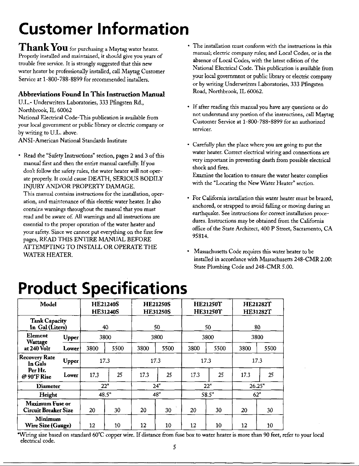
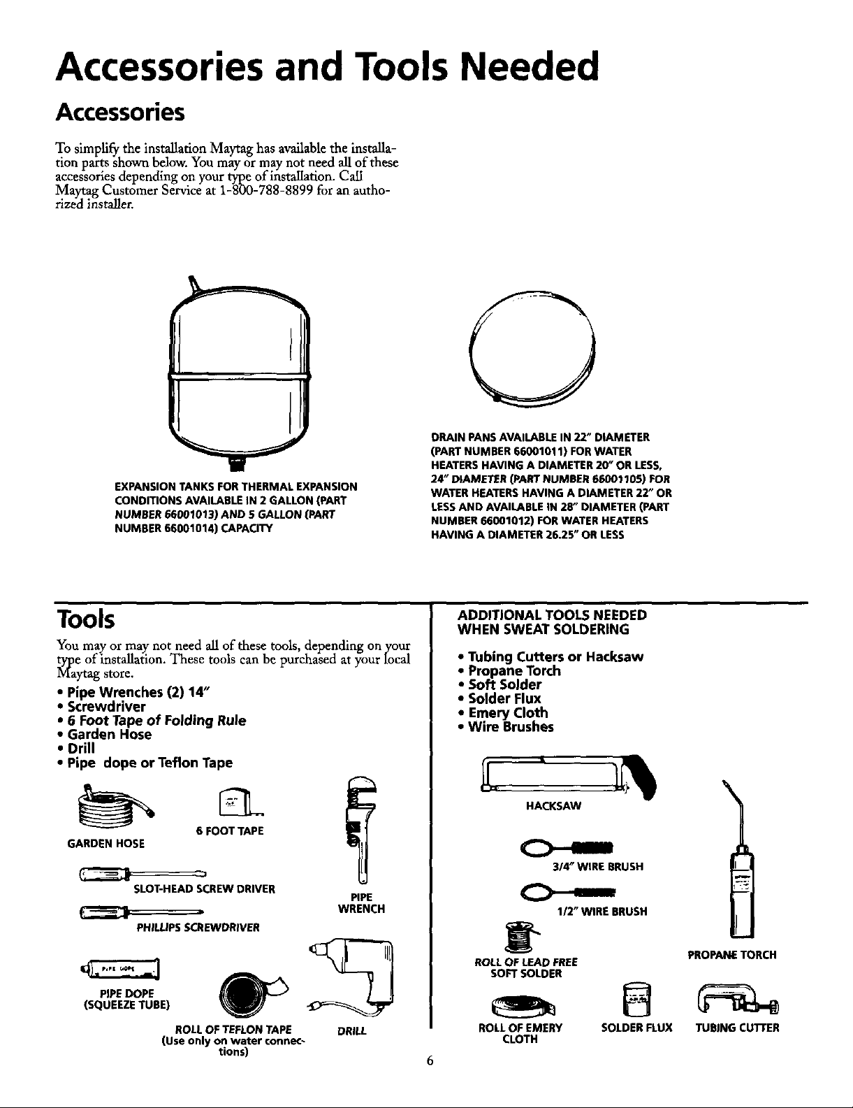
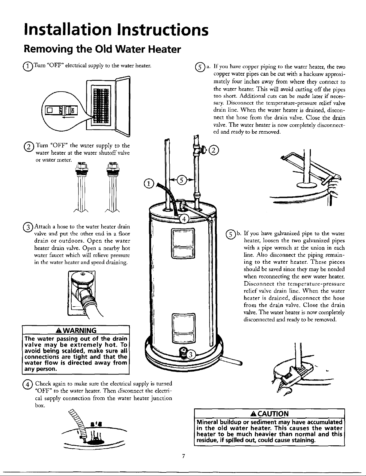
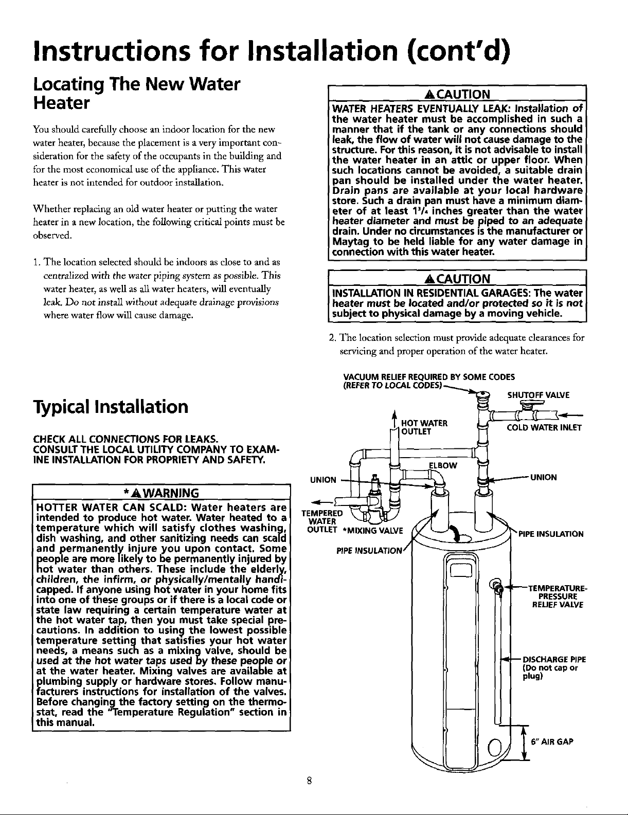
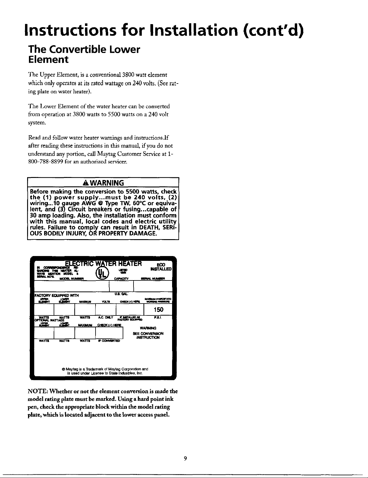
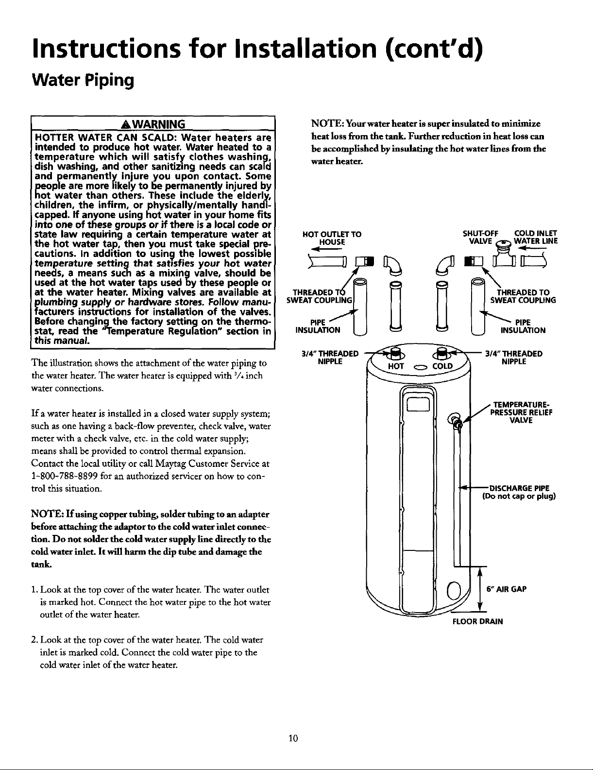


 Loading...