

Page 1
MAYTAG
Series Twelve PC
INTELLIGENT ELECTRIC
a
WATER HEATER
USER'S GUIDE
EPFICIENCY
RATING
CERTIFIED
ama
GAMA certification applies to all residential
electric water heaters with capacities of 20 to
120 Gallons. Input rating of 12 Kw or less at a
voltage no greater than 250 V.
Model Numbers
HE21250PC
HE21282PC
FOR POTABLE WATER
HEATING ONLY
NOT SUITABLE FOR
SPACE HEATING
A WARNING
READ THE GENERAL SAFETY SECTION BEGINNING ON INSIDE
COVER AND THEN THIS ENTIRE MANUAL BEFORE INSTALLING OR
OPERATING THIS WATER HEATER.
Save this Manual for Future Reference.
___________________________________
Caution:
Read and Follow All
Safety Rules and
Operating Instructions
Before First Use of
This Product.
Page 2

Safety Instructions
AWARNING
Improper installation, adjustment, alteration, service
or maintenance can cause DEATH, SERIOUS BODILY
INJURY, OR PROPERTY DAMAGE. Refer to this manu
al for assistance consuit your local utility or call
Maytag Customer Service at 1-800-788-8899 for an
authorized servicer for further information.
AWARNING
HAZARD OF ELECTRICAL SHOCK! Before removing
any access panels or servicing the water heater,
make sure the electrical supply to the water heater
is turned "OFF". Failure to do this could result in
DEATH, SERIOUS BODILY INJURY, OR PROPERTY
DAMAGE.
AWARNING
HOTTER WATER CAN SCALD: Water heaters are
intended to produce hot water. Water heated to a
temperature which will satisfy clothes washing,
dish washing, and other sanitizing needs can scald
and permanently injure you upon contact. Some
eople are more likely to be permanently injured by
ot water than others. These include the elderly,
K
children, the infirm, or physically/mentally handi
capped. If anyone using hot water in your home fits
into one of these groups or if there is a local code or
state law requiring a certain temperature water at
the hot water tap, then you must take special pre
cautions. In addition to using the lowest possible
temperature setting that satisfies your hot water
needs, a means sucn as a mixing valve, should be
used at the hot water taps used by these people or
at the water heater. Mixing valves are available at
plumbing supply or hardware stores. Follow manu
facturers instructions for installation of the valves.
Before changing the factory setting on the thermo
stat, read the "Temperature Regulation" section in
this manual.
AWARNING
INSULATING JACKETS: When installing an external
water heater insulation jacket on an electric water
heater:
•DO NOT cover the temperature-pressure relief
valve.
• DO NOT put insulation over the access covers or
any access areas.
• DO NOT cover or remove operating instructions,
and safety related warning labels and materials
affixed to the water heater.
AWARNING
Do not use this appliance if any part of it has been
under water. An electrical short or malfunction could
occur. The water heater should be replaced.
AWARNING
At the time of manufacture this water heater was pro
vided with a combination temperature-pressures relief
valve certified by a nationally recognizeci testing labora
tory that maintains periodic inspection of production of
listed equipment or materials, as meeting the require
ments for Relief Valves and Automatic Gas Shutoff
Devices for Hot Water Supply Systems, and the latest
edition of ANSI Z21.22 and the code requirements of
ASME. If replaced, the valve must meet the require
ments of local codes, but not less than a combination
temperature and pressure relief valve certified as meet
ing the requirements for Relief Valves and Automatic
Gas Shutoff Devices for Hot Water Supply Systems, ANSI
Z21.22 by a nationally recognized testing laboratory
that maintains periodic inspection of production of list
ed equipment or materials.
The valve must be marked with a maximum set pressure
not to exceed the marked hydrostatic working pressure
of the water heater (150 Ibs./sq. in.) and a discharge
capacity not less than the water heater input rate as
shown on the model rating plate. (Electric heaters watts divided by 1000 x 3415 equal BTU/Hr. rate.)
Your local jurisdictional authority, while mandating the
use of a temperature-pressure relief valve complying
with ANSI Z21.22 and ASME, may require a valve model
different from the one furnished with the water heater.
Compliance with such local requirements must be satis
fied by the installer or end user of the water heater with
a locally prescribed temperature-pressure relief valve
installed in the designated opening in the water heater
in place of the factory furnished valve.
For safe operation of the water heater, the relief valve
must not be removed from it's designated opening or
plugged.
The temperature-pressure relief valve must be installed
directly into the fitting of the water heater designated
for the relief valve. Position the valve downward and
provide tubing so that any discharge will exit only with
in 6 inches above, or at any distance below the struc
tural floor. Be certain that no contact is made with any
live electrical part. The discharge opening must not be
blocked or reduced in size under any circumstances.
Excessive length, over 30 feet, or use of more than four
elbows can cause restriction and reduce the discharge
capacity of the valve.
No valve or other obstruction is to be placed between
the relief valve and the tank. Do not connect tubing
directly to discharge drain unless a 6" air gap is provid
ed. To prevent bodily injury, hazard to life, or property
damage, the relief valve must be allowed to discharge
water in quantities should circumstances demand. If the
discharge pipe is not connected to a drain or other suit
able means, the water flow may cause property damме.
The Discharge Pipe;
• Must not be smaller in size than the outlet pipe size of
the valve, or have any reducing couplings or other
restrictions.
• Must not be plugged or blocked.
• Must be of material listed for hot water distribution.
• Must be installed so as to allow complete drainage of
both the temperature-pressure relief valve, and the
discharge pipe.
• Must terminate at an adequate drain.
• Must not have any valve between the relief valve and
tank.
Page 3

Safety Instructions (cont'd)
▲ WARNING
WATER HEATERS EQUIPPED FOR ONE VOLTAGE
ONLY; This water heater is equipped for one type
voltage only. Check the rating plate near the bot
tom access panel for the correct voltage. DO NOT
use this water heater with any voltage other than
the one shown on the model rating plate. Failure to
use the correct voltage can cause problems which
can result in DEATH, SERIOUS BODILY INJURY. OR
PROPERTY DAMAGE. If you have any questions or
doubts consuit your eiectric company.
▲ CAUTION
WATER HEATERS EVENTUALLY LEAK: Installation of
the water heater must be accomplished in such a
manner that if the tank or any connections should
leak, the flow of water wilt not cause damage to the
structure. For this reason, it is not advisabie to instaii
the water heater in an attic or upper floor. When
such locations cannot be avoided, a suitable drain
pan shouid be instalied under the water heater.
Drain pans are available at your local hardware
store. Such a drain pan must have a minimum diam
eter of at least 1% inches greater than the water
heater diameter and must be piped to an adequate
drain. Under no circumstances is the manufacturer to
be held liable for any water damage in connection
with this water heater.
Page 4

Table of Contents
Safety Instructions.................................................................................................................................................................2^3
Table of Contents.......................................................................................................................................................................4
Customer Information............................................................................................................................................................... s
Product Specifications............................................................................................................................................................... 5
Accessories and Tools Needed....................................................................................................................................................6
Accessories............................................................................................................................................................................6
Tools.................................................................................................................................................................................... 6
Instructions for Installation................................................................................................................................................... 7-22
Removing the Old Water Heater....................................................................................................................................... ..7
Locating the New Water Heater............................................................................................................................................8
Typical Installation................................................................................................................................................................8
The Convertible Lower Element...........................................................................................................................................9
Water Piping........................................................................................................................................................................10
Temperature-Pressure Rehef Valve.................................................................................................................................... 11
Filling the Water Heater......................................................................................................................................................12
Converting the Lower Element......................................................................................................................................12-14
Wiring Diagram................................................................................................................................................................. 15
Wiring..................................................................................................................................................................................16
Selecting Thermostat Location........................................................................................................................................... 17
Routing Wire Harness to Location.................................................................................................................................17
Thermostat Removal................................................................................................................................................. 17,18
Remote Thermostat Wiring at Water Heater............................................................................................................ 18-20
Remote Thermostat Installation and Wiring.............................................................................................................20,21
Installation Checklist......................................................................................................................................................... 22
Instructions for Operation...................................................................................................................................................23-26
Temperature Regulation......................................................................................................................................................23
Temperature Conditions......................................................................................................................................................23
Programming the Thermostat........................................................................................................................................ 23-26
Service and Maintenance................................................................................................................................................... 27-31
Temperature-Pressure Relief Valve Operation................................................................................................................... 27
Draining...............................................................................................................................................................................27
Element Cleaning and Replacement...............................................................................................................................28'30
Drain Valve Washer Replacement......................................................................................................................................31
Service................................................................................................................................................................................ 31
Troubleshooting.................................................................................................................................................................. 32-35
Start Up Conditions.............................................................................................................................................................32
Thermal Expansion.........................................................................................................................................................32
Strange Sounds............................................................................................................................................................. 32
Operational Conditions.................................................................................................................................................. 32,33
Smelly Water..................................................................................................................................................................32
Air in Hot Water Faucets................................................................................................................................................32
Rumbling Noise..............................................................................................................................................................32
High Temperature Shut Off System......................................................................................................................... 32,33
Not Enough Hot Water...................................................................................................................................................33
Water is Too Hot............................................................................................................................................................ 33
Thermostat Diagnostics.................................................................................................................................................. 34
Leakage Checkpoints..................................................................................................................................................... 35
Repair Parts List.................................................................................................................................................................37-39
Warranty.................................................................................................................................................................................. 40
4
Page 5

Customer Information
Thank You for purchasing a Maytag water heater.
Properly installed and maintained, it should give you years of
trouble free service. It is strongly suggested that this new
water heater be professionally installed., call Maytag Customer
Service at 1-800-788-8899 for recommended installers.
Abbreviations Found In This Instruction Manual
U.L.- Underwriters Laboratories, 333 Pfingsten Rd.,
Northbrook, IL 60062
National Electrical Code-This publication is available from
your local government or public library or electric company or
by writing to U.L. above.
ANSI-American National Standards Institute
• Read the “Safety Instructions” section, pages 2 and 3 of this
manual first and then the entire manual carefully. If you
don’t follow the safety rules, the water heater wiU not oper
ate properly. It could cause DEATH, SERIOUS BODILY
INJURY AND/OR PROPERTY DAMAGE.
This manual contains instructions for the installation, oper
ation, and maintenance of this electric water heater. It also
contains warnings throughout the manual that you must
read and be aware of. All warnings and all instructions are
essential to the proper operation of the water heater and
your safety. Since we cannot put everything on the first few
pages, READ THIS ENTIRE MANUAL BEFORE
ATTEMPTING TO INSTALL OR OPERATE THE
WATER HEATER.
The installation must conform with the instructions in this
manual; electric company rules; and Local Codes, or in the
absence of Local Codes, with the latest edition of the
National Electrical Code. This publication is available from
your local government or public library or electric company
or by writing Underwriters Laboratories, 333 Pfingsten
Road, Northbrook, IL 60062.
If after reading this manual you have any questions or do
not understand any portion of the instructions, call Maytag
Customer Service at 1-800-788-8899 for an authorized
servicer.
Carefully plan the place where you are going to put the
water heater. Correct electrical wiring and connections are
very important in preventing death from possible electrical
shock and fires.
Examine the location to ensure the water heater complies
with the “Locating the New Water Heater” section.
For California installation this water heater must be braced,
anchored, or strapped to avoid falling or moving during an
earthquake. See instructions for correct installation proce
dures. Instructions may be obtained from the California
office of the State Architect, 400 P Street, Sacramento, CA
95814.
Massachusetts Code requires this water heater to be
installed in accordance with Massachusetts 248-CMR 2.00:
State Plumbing Code and 248-CMR 5.00.
Product Specifications
Model HE21250PC HE21282PC
Tank Capacity
In Gallons
Element Upp„
at 240 Volt Lower
Recovery Rate Upper
@ 90°F Rise Lower 17.3 1 25 17.3 25
Diameter 22" 26.25"
Height 58.5" 62"
Maximum Fuse or
Circuit Breaker Size 20
Minimum
Wire Size (Gauge)*
*Wiring size based on standard 60°C copper wire. If distance from
fuse box to water heater is more than 90 feet, refer to your local
electrical code.
3800 1 5500 3800 1 5500
12
50 80
3800 3800
17.3
30 20
10 12
5
17.3
30
10
Page 6
Accessories and Tools Needed
Accessories
To simplify the installation Maytag has available the installa
tion parts shown below. You may or may not need all of these
accessories depending on your type of installation. Call
Maytag Customer Service at 1-800-788-8899 for an autho
rized installer.
DRAIN PANS AVAIUBLE IN 22" DIAMETER
(PART NUMBER 66001011) FOR WATER
HEATERS HAVING A DIAMETER 20" OR LESS,
EXMNSION TANKS FOR THERMAL EXPANSION
CONDITIONS AVAILABLE IN 2 GALLON (PART
NUMBER 66001013) AND 5 GALLON (PART
NUMBER 66001014) CAPACITY
24" DIAMETER (PART NUMBER 66001105) FOR
WATER HEATERS HAVING A DIAMETER 22" OR
LESS AND AVAILABLE IN 28" DIAMETER (PART
NUMBER 66001012} FOR WATER HEATERS
HAVING A DIAMETER 26.25" OR LESS
Tools
You may or may not need all of these tools, depending on your
type of installation. These tools can be purchased at your local
Maytag store.
• Pipe Wrenches (2) 14"
• Screwdriver
• 6 Foot Tape of Folding Rule
• Garden Hose
• Drill
• Pipe dope or Teflon Tape
GARDEN HOSE
SLOT-HEAD SCREW DRIVER
PHILLIPS SCREWDRIVER
PIPE DOPE
(SQUEEZE TUBE)
6 FOOT TAPE
ROLL OF TEFLON TAPE
(Use only on water connec
tions)
PIPE
WRENCH
DRILL
ADDITIONAL TOOLS NEEDED WHEN SWEAT SOLDERING
• Tubing Cutters or Hacksaw
• Propane Torch
• Soft Solder
• Solder Flux
• Emery Cloth
• Wire Brushes
HACKSAW
3/4" WIRE BRUSH
1/2" WIRE BRUSH
ROLL OF LEAD FREE
SOFT SOLDER
a
ROLL OF EMERY
CLOTH
SOLDER FLUX TUBING CUTTER
\
A
PROPANE TORCH
Page 7
Installation Instructions
Removing the Old Water Heater
^^Turn “OFF" electrical supply to the water heater. a.
Turn “OFF” the water supply to the
©
water heater at the water shutofif valve
or water meter.
Attach a hose to the water heater drain
valve and put the other end in a floor
drain or outdoors. Open the water
heater drain valve. Open a nearby hot
water faucet which will relieve pressure
in the water heater and speed draining.
If you have copper piping to the water heater, the two
copper water pipes can be cut with a hacksaw approxi
mately four inches away from where they connect to
the water heater. This will avoid cutting off the pipes
too short. Additional cuts can be made later if neces
sary. Disconnect the temperature-pressure relief valve
drain line. When the water heater is drained, discon
nect the hose from the drain valve. Close the drain
valve. The water heater is now completely disconnect
ed and ready to be removed.
b. If you have galvanized pipe to the water
©
heater, loosen the two galvanized pipes
with a pipe wrench at the union in each
line. Also disconnect the piping remain
ing to the water heater. These pieces
should be saved since they may be needed
when reconnecting the new water heater.
Disconnect the temperature-pressure
relief valve drain line. When the water
heater is drained, disconnect the hose
from the drain valve. Close the drain
valve. The water heater is now completely
disconnected and ready to be removed.
AWARNING
The water passing out of the drain
valve may be extremely hot. To
avoid being scalded, make sure all
connections are tight and that the
water flow is directed away from
any person.
Check again to make sure the electrical supply is turned
“OFF” to the water heater. Then disconnect the electri
cal supply connection from the water heater junction
box.
A CAUTION
Mineral buildup or sediment may have accumulated
in the old water heater. This causes the water
heater to be much heavier than normal and this
residue, if spilled out, could cause staining.
Page 8
Instructions for Installation (cont'd)
Locating The New Water Heater
You should carefully choose an indoor location for the new
water heater, because the placement is a very important con
sideration for the safety of the occupants in the building and
for the most economical use of the appliance. This water
heater is not intended for outdoor installation.
Whether replacing an old water heater or putting the water
heater in a new location, the following critical points must be
observed.
1. The location selected should be indoors as close to and as
centralized with the water piping system as possible. This
water heater, as well as all water heaters, will eventually
leak. Do not install without adequate drainage provisions
where water flow will cause damage.
A CAUTION
WATER HEATERS EVENTUALLY LEAK: Installation of
the water heater must be accomplished in such a
manner that if the tank or any connections should
leak, the flow of water will not cause damage to the
structure. For this reason, it is not advisable to install
the water heater in an attic or upper floor. When
such locations cannot be avoided, a suitable drain
pan should be installed under the water heater.
Drain pans are available at your local hardware
store. Such a drain pan must have a minimum diam
eter of at least IV« inches greater than the water
heater diameter and must be piped to an adequate
drain. Under no circumstances is the manufacturer or
Maytag to be held liable for any water damage in
connection with this water heater.
A CAUTION
INSTALLATION IN RESIDENTIAL GARAGES: The water
heater must be located and/or protected so it is not
subject to physical damage by a moving vehicle.
2. The location selection must provide adequate clearances for
servicing and proper operation of the water heater.
VACUUM RELIEF REQUIRED BY SOME CODES
Typical Installation
CHECK ALL CONNECTIONS FOR LEAKS.
CONSULT THE LOCAL UTILITY COMPANY TO EXAM
INE INSTALLATION FOR PROPRIETY AND SAFETY.
^ A WARNING
HOTTER WATER CAN SCALD: Water heaters are
intended to produce hot water. Water heated to a
temperature which will satisfy clothes washing,
dish washing, and other sanitizing needs can scald
and permanently injure you upon contact. Some
people are more likely to be permanently injured by
not water than others. These include the elderly,
children, the infirm, or physically/mentally handi
capped. If anyone using not water in your home fits
into one of these groups or if there is a local code or
state law requiring a certain temperature water at
the hot water tap, then you must take special pre
cautions. In addition to using the lowest possible
temperature setting that satisfies your hot water
needs, a means sucri as a mixing valve, should be
used at the hot water taps used by these people or
at the water heater. Mixing valves are available at
plumbing supply or hardware stores. Follow manu
facturers instructions for installation of the valves.
Before changing the factory setting on the thermo
stat, read the "Temperature Regulation" section in
this manual.
Page 9

Instructions for Installation (cont'd)
The Convertible Lower
Element
The Upper Element, is a conventional 3800 ■watt element
which only operates at its rated wattage on 240 volts.
(See rating plate on water heater).
The Lower Element of the water heater can be converted
from operation at 3800 watts to 5500 watts on a 240 volt
system.
Read and follow water heater warnings and instructions. If
after reading these instructions in this manual, if you do not
understand any portion, call Maytag Customer Service at
1-800-788-8899 for an authorized servicer.
AWARNING
Before making the conversion to 5500 watts, check
the (1) power supply...must be 240 volts. (2)
wiring...10 gauge AWG @ Type TW, 60°C or equiva
lent, and (3) Circuit breakers or fusing...capable of
30 amp loading. Also, the installation must conform
with this manual, local codes and electric utility
rules. Failure to comply can result in DEATH, SERI
OUS BODILY INJURY, OR PROPERTY DAMAGE.
M
M
WKV*
FACTORY EQUIPPED WTm
. WATTE WAm WATTS A.C. ONLT lP*l»TMUDAt,_
OPtlCWAL WATTMaE
WATTS WATTS WATTS IF OONWRTED
NOTE: Whether or not the element conversion is made the
model rating plate must be marked. Using a hard point ink
pen, check the appropriate block within the model rating
plate, vriiich is located adjacent to the lower access panel.
ELECTRIC WATER HEATER
Tm HUTER Mr
----
----
^
Maytag a Trademark of Maytag Corporation and
Is used under License to State Industries, Inc.
w^
(©
IWMAIIII yqtTt CMKKWHWg HWHWWa
mCTORY BOUPfED
CHECK
----------------------
INSTALLED
----------------------------------------
hMXHUH HVMOVTAHO
WARNINO
SEE CONVERSION
INSTRUCTION
ECO
150
Page 10
Instructions for Installation (cont'd)
Water Piping
A WARNING
HOTTER WATER CAN SCALD: Water heaters are
intended to produce hot water. Water heated to a
temperature which will satisfy clothes washing,
dish washing, and other sanitizing needs can scald
and permanently injure you upon contact. Some
eople are more likely to be permanently injured by
ot water than others. These include the elderly,
R
children, the infirm, or physically/mentally handi
capped. If anyone using not water in your home fits
into one of these groups or if there is a local code or
state law requiring a certain temperature water at
the hot water tap, then you must take special pre
cautions. In addition to using the lowest possible
temperature setting that satisfies your hot water
needs, a means sucri as a mixing valve, should be
used at the hot water taps used by these people or
at the water heater. Mixing valves are available at
plumbing supply or hardware stores. Follow manu
facturers instructions for installation of the valves.
Before changing the factory setting on the thermo
stat, read the "Temperature Regulation" section in
this manuai.
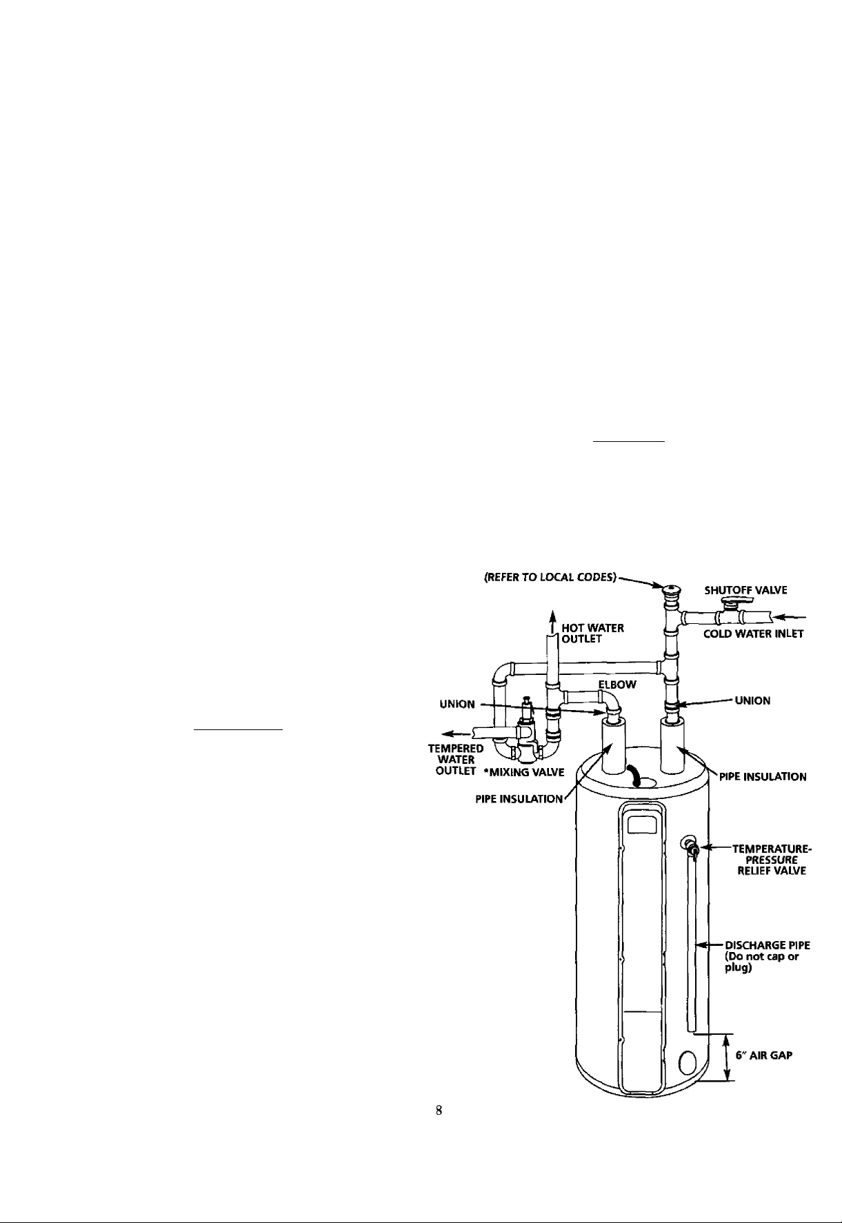
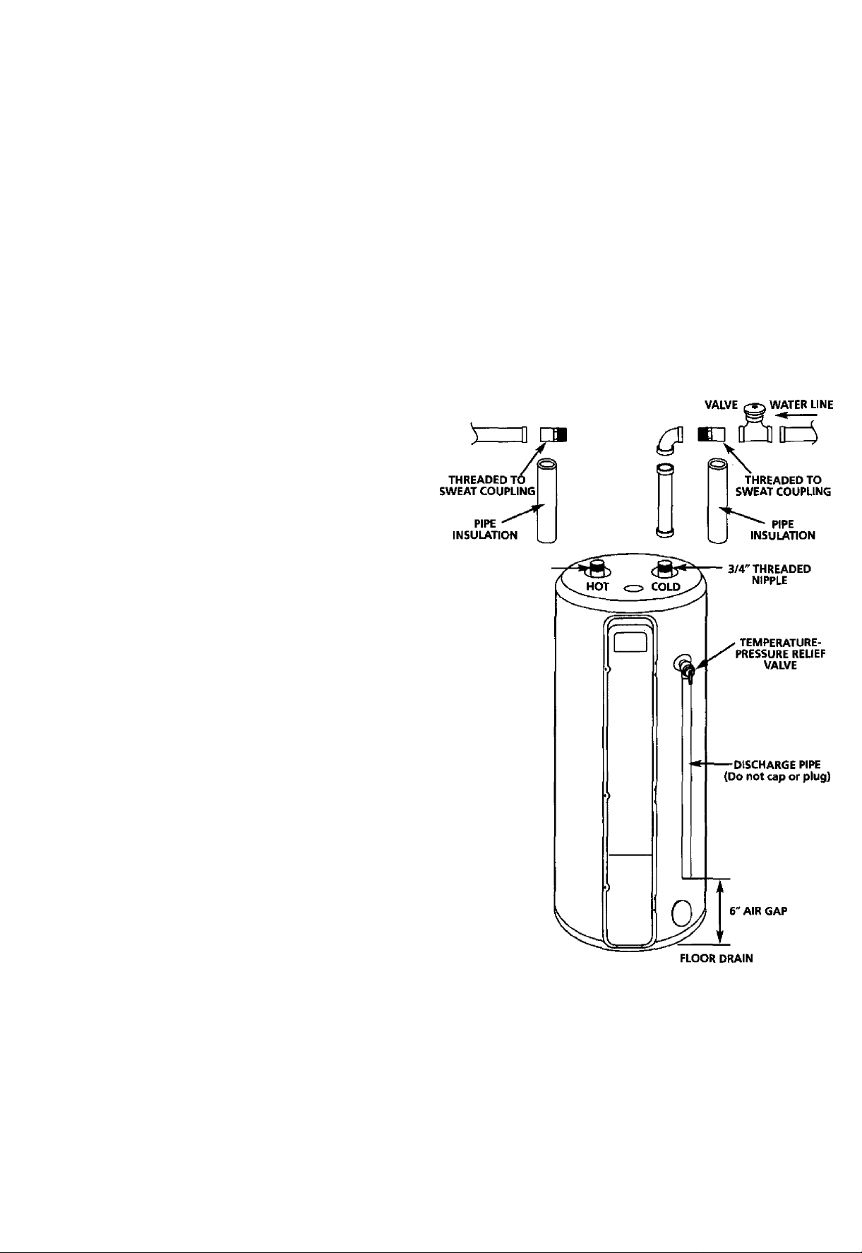
The illustration shows the attachment of the water piping to
the water heater. The water heater is equipped with ^/4 inch
water connections.
NOTE: Your water heater is super insulated to minimize
heat loss from the tank. Further reduction in heat loss can
be accomplished by insulating the hot water lines from the
water heater.
HOT OUTLET TO
HOUSE
-----
3/4" THREADED
NIPPLE
SHUT-OFF COLD INLET
If a water heater is installed in a closed water supply system;
such as one having a back-flow preventer, check valve, water
meter with a check valve, etc. in the cold water supply;
means shall be provided to control thermal expansion.
Contact the local utility or call Maytag Customer Service at
1-800-788-8899 for an authorized servicer on how to con
trol this situation.
NOTE: If using copper tubing, solder tubing to an adapter
before attaching the adaptor to the cold water inlet connec
tion. Do not solder the cold water supply line direcdy to the
cold water inlet. It will harm the dip tube and damage the
tank.
1. Look at the top cover of the water heater. The water outlet
is marked hot. Connect the hot water pipe to the hot water
outlet of the water heater.
2. Look at the top cover of the water heater. The cold water
inlet is marked cold. Connect the cold water pipe to the
cold water inlet of the water heater.
10
Page 11
Instructions for Installation (cont'd)
Temperature-Pressure Relief Valve
AWARNING
At the time of manufacture this water heater was provid
ed with a combination temperature-pressures relief valve
certified by a nationally recognized testing laboratory that
maintains periodic inspection of production of listed
equipment or materials, as meeting the requirements for
Relief Valves and Automatic Gas Shutoff Devices for Hot
Water Supply Systems, and the latest edition of ANSI
Z21.22 and the code requirements of ASME. If replaced,
the valve must meet the requirements of local codes, but
not less than a combination temperature and pressure
relief valve certified as meeting the requirements for
Relief Valves and Automatic Gas Shutoff Devices for Hot
Water Supply Systems, ANSI Z21.22 by a nationally recog
nized testing laboratory that maintains periodic inspection
of production of listed equipment or materials.
The valve must be marked with a maximum set pressure
not to exceed the marked hydrostatic working pressure of
the water heater (150 Ibs./sq. in.} and a discharge capacity
not less than the water heater input rate as shown on the
model rating plate. (Electric heaters - watts divided by
1000 X 3415 equal BTU/Hr. rate.)
Your local jurisdictional authority, while mandating the
use of a temperature-pressure relief valve complying with
ANSI Z21.22 and ASME, may require a valve model differ
ent from the one furnished with the water heater.
Compliance with such local requirements must be satisfied
by the installer or end user of the water heater with a
locally prescribed temperature-pressure relief valve
installed in the designated opening in the water heater in
place of the factory furnished valve.
For safe operation of the water heater, the relief valve
must not be removed from it's designated opening or
plugged.
The temperature-pressure relief valve must be installed
directly into the fitting of the water heater designated for
the relief valve. Position the valve downward and provide
tubing so that any discharge will exit only within 6 inches
above, or at any distance below the structural floor. Be
certain that no contact is made with any live electrical
part. The discharge opening must not be blocked or
reduced in size under any circumstances. Excessive length,
over 30 feet, or use of more than four elbows can cause
restriction and reduce the discharge capacity of the valve.
No valve or other obstruction is to be placed between the
relief valve and the tank. Do not connect tubing directly to
discharge drain unless a 6” air gap is provided. To prevent
bodily Injury, hazard to life, or property damage, the relief
valve must be allowed to discharge water in quantities
should circumstances demand. If the discharge pipe is not
connected to a drain or other suitable means, the water
flow may cause property damage.
The Discharge Pipe:
• Must not be smaller in size than the outlet pipe size of
the valve, or have any reducing couplings or other
restrictions.
• Must not be plugged or blocked.
• Must be of material listed for hot water distribution.
• Must be installed so as to allow complete drainage of
both the temperature-pressure relief valve, and the dis
charge pipe.
• Must terminate at an adequate drain.
• Must not have any valve between the relief valve and
tank.
AWARNING
The temperature-pressure relief valve must be manu
ally operated at least once a year. Caution should be
taken to ensure that (1) no one is in front of or
around the outlet of the temperature-pressure relief
valve discharge line, and (2) the water manually dis
charged will not cause any bodily injury or property
damage because the water may be extremely hot.
If after manually operating the valve, it fails to com
pletely reset and continues to release water, immedi
ately close the cold water inlet to the water heater,
follow the draining instructions, and replace the
temperature-pressure relief valve with a new one.
PiPE
INSULATION
CONOUIT
^ ^^TEMPERATURE-
^ RELIEF VALVE
WARNING “RELIEF VALVE OPENING
This water heater is provided with a combination Tempefalure-PresSLire Relief Valve listed as complying with
the standard for Reliet Valves and Automatic Gas Shutoff Devices for Hot l/Vater Supply Systems, ANS .22
and the code rei^irements of ASME.
Your local jurisdictionai authority, while mandating the use ot a Temperature-Pressure Relief Valve complying
with ANS Z21-22 and ASME, may require a valve model different from the one furnished with the water twater
Compliance with such local requirements must be satisfied by the installer or end user
a locally prescribed Temperature-Pressure Relief Valve ir^stalled in the designated opening in the water
T&p relief
VALVE PROBE
MUST EXTEND
INTO TANK
• If a short shank (less than 2‘j temperature-pressure relief valve Is to be installed
(as stwFiTr). a rMpplo and coupting rrtusl be used.
• If a long shank (2" or longer} is to be installed, do not use the nipple and coupling.
"Install Temperature-Pressure protective equipment required by local codes, but not less than a combina
tion Temperature-Pressure Relief Valve certified as meeting the requirements for Relief Valves and
Automatic Gas Shutoff Devices for Mot-Water Supply Systems, MS Z21.22 by a nationally recognized test
ing laboratory that maintains periodic inspection of production of Hated equipment or materials. The valve
must be oriented, provided with tubing, or otherwise installed so that discharge carr exit only wHhir 6 inches
above, or at any distance below ti>e stiuctural floor, and cannot contact any live eledricaf part.''
For safe operatron of the water heater, the Relief Valve must not be removed or plugged.
See manual heading - Temperature-Pressure Relief Valve" lor installation and maintenance of Relief
Valve, discharge pipe and other safety precautions.
(IV.' X V.
èRASS
NIPPLE
TAP
SHANK
LENGTH
INSULATION
:
----
PRESSURE
DISCHARGE PIPE
(Do not cap or plug)
of the water heater with
11
COLD
Page 12
Instructions for Installation (cont'd)
Filling the Water Heater
To fill the water heater with water:
1. Close the water heater drain valve by turning the handle to
the right (clockwise). The drain valve is on the lower front
of the water heater.
2. Open the cold water supply valve to the water heater.
NOTE: The cold water supply valve must be left open
when the water heater is in use.
3. To insure complete filling of the tank, allow air to exit by
opening the nearest hot water faucet. Allow water to run
until a constant flow is obtained. This will let air out of the
water heater and the piping.
A CAUTION
Never use this water heater unless it is completely
full of water. To prevent damage to the tank and
heating element, the tank must be filled with
water. Water must flow from the hot water faucet
before turning "ON" power.
4. Check aU new water piping for leaks. Repair as needed.
Converting the Lower Element
AWARNING
Before making the conversion to 5500 watts, check
the (1) power supply...must be 240 volts, (2)
wiring...10 gauge AWG @ Type TW, 60°C or equiva
lent, and (3) Circuit breakers or fusing...capable of
30 amp loading. Also, the installation must conform
with this manual, local codes and electric utility
rules. Failure to comply can result in DEATH, SERI
OUS BODILY INJURY, OR PROPERTY DAMAGE.
. electric water heater ECO
wMvt MPtTiON yaosL % lUI 1
FACTORY EQUIPPED wim
ÆBt ¿SiSlr UWIUM
MootLiiUMwn ''isy cmotT anuLMiMBi
VOLTI CHKKIiOHM *iSSSSwSBSSSr
UAOAL
«BP IMTAIIED
150
warning
SEE CONVERSION
WATTS WATIB WATTS IFCONWITSD
<9 Mayiag is a Trademark of Maytag Corporation and
is used under Lioensa to State Industries, Inc.
M9TRUCD0N
These instructions only cover the conversion of the convert
ible element, read this entire manual before attempting to
install or operate the water heater. The water heater is factory
set to operate at 3800 watts. The lower element can be con
verted to operate at 5500 watts. Refer to “The Convertible
Lower Element” section.
The Upper Element is a conventional 3800 watt element
which only operates at its rated wattage on 240 volts, (See rat
ing plate on water heater).
The Lower Element of the water heater can be converted
from operation at 3800 watts to 5500 watts on a 240 volt sys
tem.
If after reading these instructions and this manual, if you do
not understand any portion, call Maytag Customer Service at
1-800-788-8899 for an authorized servicer.
NOTE: Whether or not the element conversion is made the
model rating plate must be marked. Using a hard point ink
pen, check the appropriate block vnthin the model rating
plate, which is located adjacent to the lower access panel.
Necessary element conversion parts are located in a small bag
contained within the large plastic manual envelope attached
to the side of the water heater.
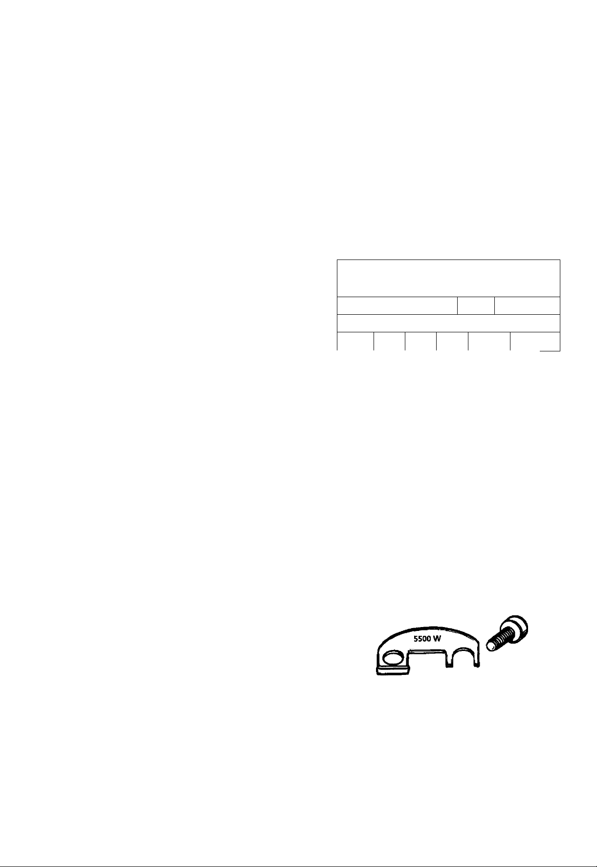
CONVERSION PARTS
SCREW
BUSS BAR
12
Page 13

Instructions for Installation (cont'd)
Converting the Lower Element (cont'd)
1. Before beginning the conversion turn “OFF” electric
power supply to the water heater.
A WARNING
HAZARD OF ELECTRICAL SHOCK! Before removing
any access panels or servicing the water heater,
make sure the electrical supply to the water heater
is turned "OFF". FAILURE TO DO THIS COULD
RESULT IN DEATH, SERIOUS BODILY INJURY, OR
PROPERTY DAMAGE.
2. The convertible element is located behind the lower access
panel of the water heater. Remove the screw securing the
access panel, and remove panel.
4. Remove the screws from terminal 2 of the element, and
move the looped end of the wire aside.
5. The buss bar is labeled 5500 W. Place the buss bar over ter
minals 2 and 3 with the 5500 W visible. Install the extra
screw provided into terminal 3.
3. Remove the flap of insulation to expose the opening.
6. The wire removed from terminal 2 has a looped end. It
must remain looped and now be placed (as shown) on top
of the buss bar, over the opening of terminal 2, and secured
using the remaining screw.
7. Tighten terminals 2 and 3 to ensure proper electrical con
nection.
AWARNING
Failure to tighten terminal screws can cause a fire
which can result in DEATH, SERIOUS BODILY INJURY,
OR PROPERTY DAMAGE.
13
Page 14

Instructions for Installation (cont'd)
Converting the Lower Element (cont'd)
8. Press the insulation back in place so that it completely cov
ers the thermlster and element.
9. Replace the access panel.
10. Complete wiring to the water heater, or if completed, turn
“ON” electric power to the water heater after filling the
tank with water.
A CAUTION
Never use this water heater unless it is completely
full of water. To prevent damage to the tank and
heating element, the tank must be filled with water.
Water must flow from the hot water faucet before
turning "ON" power.
14
Page 15

Instructions for Installation (cont'd)
Wiring Diagram
TO ELECTRIC
POWER supply
Page 16

Instructions for Installation (cont'd)
Wiring
A CAUTION
Never use this water heater unless it is completely
full of water. To prevent damage to the tank and
heating element, the tank must be filled with
water. Water must flow from the hot water faucet
before turning on power.
You must pro\ide all wiring of the proper size outside of the
water heater. You must obey local codes and electric company
requirements when you install this wiring.
If you are not familiar with electric codes and practices, or if
you have any doubt, even the slightest doubt, in your ability to
connect the wiring to this water heater, obtain the service of a
competent electrician. Call Maytag Customer Service at
1-800-788-8899 for an authorized servicer.
AWARNING
WATER HEATERS EQUIPPED FOR ONE VOLTAGE
ONLY; This water heater Is equipped for one type
voltage only. Check the rating plate near the bot
tom access panel for the correct voltage. DO NOT
use this water heater with any voltage other than
the one shown on the model rating plate. Failure to
use the correct voltage can cause oroblems which
can result in DEATH, SERIOUS BODILY INJURY, OR
PROPERTY DAMAGE, lif you have any questions or
doubts consult your electric company.
A CAUTION
If wiring from your fuse box or circuit breaker box
was aluminum for your old water heater, replace it
with copper wire. If you wish to reuse the existing
aluminum wire, have the connection at the water
heater made by a competent electrician. Call
Maytag Customer Service at 1-800-788-8899 for an
authorized servicer.
C. Flexible metal conduit or 3 metallic tubing shall be per
mitted for grounding if all the following conditions are
met:
1. The length in any ground return path does not exceed
6 feet.
2. The circuit conductors contained therein are protected
by overcurrent devices rated at 20 amperes or less.
3. The conduit or tubing is terminated in fittings
approved for grounding.
For complete grounding details and aU allowable exceptions,
refer to the latest edition of the National Electrical Code.
4. A standard Vz" conduit opening has been made in the water
heater junction box for the conduit connection.
5. A wiring diagram (See “Wiring Diagram” Section) has been
supplied showing the connections between the water heater
and the power supply. You can easily see the connection by
removing the junction box cover on top of the water heater.
Connect red to red, black to black, and the ground wire to
the green ground screw in the junction box of the water
heater.
6. Use wire nuts and connect the power supply wiring to the
wires inside the water heater’s junction box,
7. The water heater must be electrically “grounded” by the
installer. A green ground screw has been provided on the
water heater's junction box. Connect ground wire to this
location.
8. Replace the wiring junction cover using the screw provided.
1. Provide a way to easily shut off the electric power when
working on the water heater. This could be with a circuit
breaker or fuse block in the entrance box or a separate dis
connect switch.
2. Install and connect a circuit directly from the main fuse or
circuit breaker box. This circuit must be the right size and
have its own fuse or circuit breaker. Refer to the chart in
the “Product Specifications" section for the correct size
wire and fuse or circuit breaker.
3. If metal conduit is used for the grounding conductor:
A. The grounding electrode conductor shall be of copper,
aluminum, or copperclad aluminum. The material shall
be of one continuous length without a splice or joint.
B. Rigid metal conduit, intermediate metal conduit, or
electrical metallic tubing may be used for the grounding
means if conduit or tubing is terminated in fittings
approved for grounding.
16
Page 17

Instructions for Installation (cont'd)
Selecting Thermostat Location
1, The programmable thermostat control module is shipped
attached to the front of the water heater, located behind the
hinged cover panel.
If this thermostat location is acceptable to the homeowner,
proceed directly to the “Installation Checklist” on page 22 and
then to “Temperature Regulation" on page 23.
2. The thermostat control module can also be installed next to
the home’s heating or heating/cooling thermostat, or in
another convenient location remote from the water heater.
6. Probe for any obstruction in the partition. In a clear area drill
a 'A" hole through the wall at the selected location.
7. Through this hole in the wall, drop a light chain or short chain
attached to a strong cord. Snag the cord with a hooked wire
from the basement. (In a home with no basement, drop the
cord from ceding and snag it at the thermostat hole location.)
8.
Attach one end of the wiring harness to the cord. Pull the
cable through the hole in the wall so that 6 inches of cable
protrudes. Other end of cable is to be routed back to the junc
tion box on top of the water heater (Step 21). Before proceed
ing, turn “OFF” the electric power supply to the water heater.
©MAYTAG ' ' ’
3. The remote location should be about 5 feet above the floor
on any wall with good air circulation at average room tem
perature.
ROUTING WIRE HARNESS TO LOCATION
4. A wiring harness kit for up to 50 feet of wiring is available
(see Repair Parts list) from your Maytag Dealer.
5. Before drilling a hole in the wall at the selected location, take
up floor moulding (quarter round or other) and drill a small
guide hole for sighting. From the basement, drill a ’A" hole in
partition floor next to guide hole (in homes with no base
ment, drill a Vi" hole through ceiling above the partition).
AWARNING
HAZARD OF ELECTRICAL SHOCK! Before removing
any access panels or servicing the water heater,
make sure the electrical supply to the water heater
is turned "OFF". Failure to do this could result in
DEATH, SERIOUS BODILY INJURY, OR PROPERTY
DAMAGE.
THERMOSTAT REMOVAL
9. Holding fingers along the top and thumb on bottom, between
the thermostat and wall plate, gently remove thermostat from
the wall plate. The thermostat will be installed at the selected
remote location in Steps 32 and 33,
17
Page 18

Instructions for Installation (cont'd)
THERMOSTAT REMOVAL (cont'd)
10. Carefully disconnect wiring harness terminal connector
from back of riiennostat.
11. Remove the wall plate from the water heater by unscrewing
the two mounting screws. The wall plate will be installed at
the selected location in Steps 28 and 29.
PLATE
13. Press the end of the thermostat cable back into the insulating
bushing. No other connections will be made to this end of
the cable.
INSULATING
BUSHING
WIRING
HARNESS
14. Close and latch outer door.
REMOTE THERMOSTAT WIRING ATWATER HEATER
IS. Remove mounting screw and right junction box cover. Also
lift up and remove black plug on left junction box cover.
Discard plug.
12. Loosen each screw in the terminal connector and remove the
wire ends. The terminal connector will be installed at the
selected remote location in Step 31.
18
Page 19

Instructions for Installation (cont'd)
16. Find the loop of thermostat wiring cable (grey colored) inside
the junction box and pub it out.
17. Cut the thermostat wiring cable in half at the top of the loop.
19. Strip the thermostat cable outer insulation back 1'A inches.
Strip the ends '/4 inch on each of the six colored wires.
20. A second terminal connector is provided in a small bag eontained within the large plastic manual envelope attached to
the side of the water heater. Loosen each screw in the termi
nal connector. Insert the six colored wires of the thermostat
cable into the terminal connector and tighten each screw to
secure each wire. Be sure to arrange wires in exact color
sequence as shown.
IS. The wire side of the loop ridiich does not have the red tape
strip on it should be cut off or pressed into the junction box
out of the way.
UNUSED
THERMOSTAT
ACTIVE THERMOSTAT
CABLE HALF
CABLE HALF
A CAUTION
The six colored insulated wires must be installed in the terminal connector exactly as shown for the thermostat to operate correctly.
21. Locate the end of the remote thermostat cable routed to the
water heater in Step 8.
19
Page 20

Instructions for Installation (cont'd)
Selecting Thermostat Location (cont'd)
22. Guide the end of the remote thermostat cable through the
hole where the black plug was removed in the left junction
box cover.
23. Strip the end of the remote thermostat cable outer insulation
back VA inches. Strip the ends V4 inch on each of the six col
ored wires.
25. CarefUly press the terminal connector and connected wires
down into the water heater junction box,
26. A strain-relief bushing is also provided in the small bag that
contained the terminal connector. Open the bushing and
place it around the remote thermostat cable exiting the junc
tion box. Press the bushing into the hole in the left junction
box cover.
24. Loosen each screw in the terminal connector one at a time
and insert wire with the same color insularion into each
numbered slot. Tighten each screw securely making sure
both wires in each slot are tight.
27. Replace the right junction box cover using the screw provid
ed. This completes the remote thermostat wiring at the water
heater.
REMOTE THERMOSTAT INSTALUTION AND WIRING
28. Locate the 6 inches of remote thermostat cable protruding
through the wall opening (from Step 8). Using the wall plate
removed in Step 11, puU the cable through opening near cen
ter of wall plate.
20
Page 21

Instructions for Installation (cont'd)
29, Fasten wall plate loosely to the wall in position shown using
the three screws provided in the plastic bag. Wall anchors are
recommended for drywall installation. Place a level on top of
the wall plate, adjust until level, and then tighten screws to
secure wall plate.
30. Strip the remote thermostat cable outer insulation back I’A
inches. Strip the ends ’/4 inch on each of the six colored wires.
A CAUTION
The six colored insulated wires must be instailed in
the terminal connector exactly as shown for the
thermostat to operate correctly.
32. Carefidly plug the wired terminal connector to the mating
pins on the thermostat back. Connector will install in one
direction only as shown.
33. Place thermostat over wall plate, press firmly, and thermostat
win snap into place on the wall plate.
31. Using the terminal connector removed in Step 12, insert the
six colored insulated wires in the remote thermostat cable
into the numbered slots in the terminal connector and tight
en each screw to secure each wire. Be sure to arrange wires in
exact color sequence as shown.
34, Turn “ON” electric power to water heater.
35. Read Temperature Regulation Warning and Temperature
Settings, then proceed to Programming the Thermostat.
21
Page 22

Instructions for Installation (cont'd)
Installation Checklist
1. Whether or not the element conversion is made, the
model rating plate must be marked. Using a hard point
ink pen, check the appropriate block within the model rat
ing plate, which is located adjacent to the lower access
panel.
2. Is the fuse or circuit breaker size correct as shown in the
chart in the “Product Specifications” section?
3. Are the wires from the circuit breaker or fuse service to the
water heater’s junction box on the correct wire size (gauge)
as shown in the chart in the “Product Specifications” sec
tion?
HOT
CONDUIT
COLD
TEMPERATURE'
PRESSURE
RELIEF VALVE
4. Is the new temperature-pressure relief valve properly
installed, and piped to an adequate drain? See
“Temperature-Pressure Relief Valve” in the “Instructions
for Installation” section.
5. Is the water heater completely filled with water? See
“Filling the Water Heater” instructions in the
“Instructions for Installation” section.
6. Will a water leak damage anything? See “Locating the
New Water Heater” in the “Instructions for Installation"
section.
7. Are the cold and hot water lines connected to the water
heater correctly? See “Water Piping” instructions in the
“Instructions for Installation” section.
8. Is there adequate clearance for maintenance around the
water heater?
9. If the programmable thermostat has been moved to a
remote location, has the wiring been done correctly?
10. Do you need to call your electric company to check your
wiring?
FAC TORY E OLH PP6 0 WITH
UH NT n m m v м т лм
■'ВВ. ¿s »
WA TT* ммтта
ELECTRIC TOfTER HEATlR eoo
>i7S MSTAllH)
i
LLM AI.
CMCKtvIHM
VO LTS
Mum
СНЕШтНЕМ
MA XIMU M
-- -- ----- -- -- ----- -- -- -- --- -- -
________________
MO ONV CTtlD
\ wAmMO
SEECONVE RSK M
\ wemucnciN
DISCHARGE PIPE
(Do not cap or
plug)
WM —«III—яотс
WO fMM PMM UIIS
ISO
p.i.1,
22
<E> Maytag is alt'adamark ot Maytag Corporation and
la U3»d undar License to State Industries, Inc.
MODEL RATING PLATE
Page 23

Instructions for Operation
Temperature Regulation Programming the Thermostat
AWARNING
HOTTER WATER CAN SCALD: Water heaters are
intended to produce hot water. Water heated to a
temperature which will satisfy clothes washing,
dish washing, and other sanitizing needs can scald
and permanently injure you upon contact. Some
eople are more likely to be permanently injured by
ot water than others. These include the elderly,
R
children, the infirm, or physically/mentally handi
capped. If anyone using hot water in your home fits
into one of these groups or if there is a local code
or state law requiring a certain temperature water
at the hot water tap, then you must take special
recautions. In addition to using the lowest possi
le temperature setting that satisfies your hot
E
water needs, a means such as a mixing valve,
should be used at the hot water taps used by these
people or at the water heater. Mixing valves are
available at plumbing supply or hardware stores.
Follow manufacturers instructions for installation of
the valves.
AWARNING
Never allow small children to use a hot water tap,
or to draw their own bath water. Never leave a
child or handicapped person unattended in a bath
tub or shower.
Before programming the settings on the thermostat, read
the "Temperature Regulation” section again.
This new programmable thermostat technology makes it pos
sible for you to enjoy all the benefits of hot water whenever
you need it and save the cost of heating water when you don’t
need it.
Simple and easy to use, the programmable control has three
basic modes of operation:
1. Manual mode - a set and forget operation.
2. Vacation mode - for those occasions when the residence
is unoccupied and there is no need for hot water.
3. Programmable mode - can be programmed for up to 24
hour a day, 7 days a week with 4 set periods a day.
Override is an optional setting that allows for temperature
adjustments during a given time period. This setting reverts
back to the previous mode of operation upon completion of
the designated override time period.
Option menu is a mode to change the factory setting for the
time clock (12 hr. clock or 24 hr. militaiy), temperature scale
(°F to °C), default heating setpoint, vacation setpoint and
maximum heating setpoint.
Temperature Conditions
VERY LOW — The thermostat minimum setback tempera
ture is 60°F.
HOT- A thermostat setting of 120°F will supply hot
water at the most economical temperatures.
VERYHOT- The thermostat maximum temperature is
160°F. It is recommended that the tempera
ture be set lower whenever possible.
NOTE: Water temperature range of 120°-140°F recom
mended by most dishwasher manufacturers.
DATE AND TIME SETTING:
Your new programmable control comes complete with a day of
the week and digital clock display. These settings are changed
using the day and time keys on the control pad. To adjust day
and/or time, depress the appropriate key button. The day of the
week scrolls left to right on the display as the “DAY” button is
depressed. The time setting can be adjusted by scrolling for
ward or backward using the + and - of the “TIME” button.
The clock is based on a 24-hour rolling display with AM and
PM appearing below the hour and minute characters.
CONSTANT TEMPERATURE DISPLAY:
The constant display screen shows the water temperature
“WATER TEMP” inside the tank. It is continually on dis
play until interrupted by a reprogram procedure, but reappears
after 20 seconds of inactivity.
MODE CHANCE
To change the mode-of-operation depress the “MODE” but
ton at the bottom of the control. The mode display will change
by scrolling from top to bottom with the Auto mode appearing
on the top of the column, followed by the Manual mode in the
middle and finally the Vacation mode at the bottom. Continue
to change between mode settings by depressing the “MODE”
button until the desired setting is displayed.
23
Page 24

Instructions for Operation (cont'd)
Programming the Thermostat (cont'd)
Normal Display
-TIME
BUTTON
MANUAI. MODE
The most basic operation of the Intelligent water heater ther
mostat is the Manual Mode. With this mode the thermostat is
set at a desired temperature and the water heater operates to
maintain that temperature. The Intelligent Maytag water heater
utilizes a special sensing device in the control system that allows
for temperature accuracy to be maintained at plus or minus 1°F.
VACATION MOOR
Vacation mode is used whenever the residency is unoccupied for
a considerable length of time (2-days or longer) and hot water is
not needed. By selecting the Vacation Mode the water heater
will maintain a reduced setting of 80 degrees untU a new opera
tion mode is selected.
PROGRAMMAR! F. MODE
The Auto mode selection permits the water heater to be pro
grammed for four periods a day, 24-hours a day and 7-days a
week. To begin programming, depress the “MODE” button
until the AUTO selection appears in the display. To activate
the Program Mode depress the “PROGRAM” button at the
top of panel. The programming mode should appear as the
next display.
The first period to program is Monday “Morn” - this period is
designated as “Mom”. By depressing the + or - of the “TIME”
button, the owner can choose the target time for the water to be
at a specific temperature. The heating elements will be activated
15 minutes before the target time to heat the water to the
desired temperature. For example, if 6:00 AM is the time the
occupant desires 130°F water for bathing, the time on the pro
grammed display would be set for 6:00 AM. The next selection
to program is the desired water temperature to have for morning
activities. In this example the temperature would be set to 130°F
by depressing either the up ( A ) arrow or the down ( ▼ ) arrow,
located next to the display panel, until the target temperature is
displayed.
Program Display
PROGRAM
BUTTON
The second period to program is Monday “Day” - the method
of setting the time and temperature are the same for all four
selected periods of the day. The second period designated
can be set to a reduced temperaUire (70°F or lower) due to the
lack of need for hot water, assuming no one is at home during
the day. If everyone leaves at 9:30 AM, this time can be entered
into the program and the heating elements would not activate
until the temperature in the tank dropped to 70°F.
The third period to program is Monday “Eve” ~ this period is
designated “Eve would usually begin when people arrive home
from their daily activities. The temperature for this period can
be adjusted to a normal hot water setting considering evening
demand like washing dishes or clothes. For example if 125°F is
the chosen temperature to have at 5:30 PM then these settings
would be entered into the program.
The fourth period to program is Monday “Nite” - this period
is designated “Nite” and is usually the beginning of decreased
hot water needs as the residents retire for the night. In the
example the temperature would be set for 70°F or lower with
the begin time set at 11:00 PM.
Program Copy - The first day of programming has now been
completed. If each succeeding day of the workweek requires the
same desired settings as those just programmed for Monday,
these settings can be copied to the remaining four days of the
week by depressing and holding the “PROGRAM” button for
several seconds. In this manner the first day’s settings are
repeated to аД four remaining weekdays.
Weekend programming - the weekend programming can be
set different than the weekday settings, if desired. Saturday and
Sunday can be separately programmed by advancing the pro
gram selection to the day marked “SA” and/or “SU”. The steps
described above for programming the four periods per day can
be repeated for the weekend only using different rimes and tem
peratures to provide desired water temperatures when needed on
the weekend.
“Day”
24
Page 25

Instructions for Operation (cont'd)
ERASE is the option that can delete all the settings that had
been programmed previously. While in the programmable
mode, depressing the “ERASE” button will delete a particular
time period that is on display. Depressing and holding the
“ERASE" button down for several seconds will erase all the set
tings for an entire week. This procedure should be adminis
tered careftillv. as erasing the entire week’s programmed set
tings will necessitate a complete reprogtamming procedure.
OVRRRÌDE is an option that can be used to temporarily
adjust water temperature for a specific length of time. If for
example there is a need for higher water temperatures during a
specific number of hours or days, the “OVERRIDE” button
can be depressed. The first screen to be displayed is the
HOURS and DAYS time menu and DESIRED
TEMPERATURE. The default time period is 3 hours. This
time can be adjusted upward or downward by using the + or - of
the “TIME” button. After holding the + “TIME” button
beyond 24 hours the hours and days designation vrili appear.
The OVERRIDE can be adjusted for both days as weU as
hours. The maximum number of days to OVERRIDE is 99.
Override Display
OPTIONAL SETTING CHANGES
There are five optional settings the owner can change in the
programmable control module. To advance to the Optional
Setting Mode, depress the “PROGRAM” and “MODE” but
tons simultaneously for four seconds. Four zeros should appear
in the upper left hand corner (0000) and a large number 1
should appear in the bottom right-hand corner. This indicates
the optional menu is on the type of time setting.
The first optional mode (1) setting involves the type of time
that will appear on the clock display. The default setting is the
normal twelve-hour clock. For military time depress either + or
- of the “TIME” button until the description 0001 appears in
the upper-left hand comer. To change back to normal time in
optional setting 1 depress either (+ or -) of the time buttons
until 0000 appears in the upper left-hand corner.
-OVERRIDE
BUTTON
After setting the time duration, the override temperature can
be adjusted by using the up ( A) arrow or the down ( ^ )
arrow, located next to the display panel, until the target tem
perature is displayed. For example, if guests arrive for the
weekend and warmer water temperatures are desired, the
occupant may adjust the temperature setting to 130°F for 2
days and 10 hours. This would control the target temperature
until the completion of the designated time and return the
thermostat to the program control that had been in operation
before the override was implemented.
The second optional mode (2) setting involves the temperature
scale. To change to the temperature setting option, depress the
up or down arrow button until the large number 2 appears in
the lower right hand corner. The default setting is in the
Fahrenheit scale. To change to Centigrade, depress either + or
' of the “TIME” button until the description 0001 appears in
the upper-left hand corner. To change back to the Fahrenheit
scale, repeat the procedure until 0000 appears in the upper-left
hand corner.
25
Page 26

Instructions for Operation (cont'd)
Programming the Thermostat (cont'd)
The third optional mode (3) setting involves the default tem
perature set point for the control. To be in this mode, depress
the up ( ▲) arrow or the down ( ^ ) arrow until a large number 3
appears in the lower right-hand corner. The default temperature
from the factory is 120°F. This wU appear in the upper-left
hand corner as 0120. To change the default setting, depress
either -t- or - of the “TIME” button until the desired default
temperature is displayed in the upper left-hand comer. The
range for set point temperature is 80°F to 160°F.
The fourth optional mode (4) setting involves the vacation tem
perature setting. This is factory set at 80°F or 0080 in the upper
left-hand corner. To change the vacation default setting, make
sure the optional mode is in the number (4) setting by depress
ing the up ( a) arrow or the down ( ^ ) arrow button until a
large number 4 is displayed in the lower right-hand corner. To
change the vacation temperature default setting, depress either +
or - of the “TIME” button until the desired vacation tempera
ture is achieved in the upper left-hand comer of the display.
The range for vacation default setting is 60°F to 120°F.
To return to regular operation of the program control, depress
the “PROGRAM” and “MODE” buttons simultaneously
again until the normal display appears. All the optional settings
that were revised will remain until they are once again reset by
using the above prescribed procedures.
SCALD WARNING is a flashing display warning any time
the temperature is adjusted above 120°F. It represents an indus
try warning that water temperatures above 120°F represent a
scald hazard when sldn surface is exposed for a small amount of
time. This is a warning and can not be removed from the screen
display.
“PWR" (POWER) BUTTON is a button at the right-hand
bottom of the panel which will activate or deactivate the display
panel. It will not turn oflFthe power to the water heater and
will not kill the power to the heating elements.
A WARNING
HAZARD OF ELECTRICAL SHOCK! Before removing
any access panels or servicing the water heater,
make sure the electrical supply to the water heater
is turned "OFF". Failure to do this could result in
DEATH. SERIOUS BODILY INJURY. OR PROPERTY
DAMAGE.
The fifth optional mode (5) setting involves the masdmum tem
perature set point. To be this mode, depress the up ( A) arrow
or the down ( ▼ ) arrow while in optional setting sequence until
a large number 5 is displayed in the lower right-hand corner.
The default factory maximum set point is 160°F or 0160 in the
upper left-hand comer. To change this setting depress either +
or - of the “TIME” button until the desired maximum set point
is achieved in the upper left-hand comer. The range for maxi
mum set point is 100°F to 160°F.
EI ECTRICAL POWER OUTAGES will not effect the
Intelligent programming or control settings. The unit has a bat
tery backup that maintains the programmed settings until the
electrical power is restored. At the time power is restored the
program will again display the settings and information that had
been available before the loss of power.
DRY FIRE PREVENTION is a feature that has been pro
grammed into the Intelligent water heater. Should someone
install or service the water heater and forget to fill the tank, the
unit will sense a rapid heat cycle beyond normal expectations
and disable the energy. A message will be displayed on the
screen to add water, at which time the unit can be re-energized.
26
Page 27

Service and Maintenance
Temperature-Pressure Relief Draining
Valve Operation
The iemperature-pressure rehef valve must be manually oper
ated at least once a year.
A WARNING
The temperature-pressure relief valve must be
manually operated at least once a year. Caution
should be taken to ensure that (1) no one is in front
of or around the outlet of the temperature-pres
sure relief valve discharge line, and (2) the water
manually discharged will not cause any property
damage or bodily injury. The water may be
extremely hot.
If after manually operating the valve, it fails to
completely reset and continues to release water,
immediately dose the cold water inlet to the water
heater, follow the draining instructions, and
replace the temperature-pressure relief valve with
a new one.
The water heater should be drained if being shut down during
freezing temperatures. Also periodic draining and cleaning of
sediment from the tank may be necessary.
1. Before beginning turn “OFF” the electric power supply to
the water heater.
HAZARD OF ELECTRICAL SHOCK! Before removing
any access panels or servicing the water heater,
make sure the electrical supply to the water heater
is turned "OFF". Failure to do this could result in
DEATH, SERIOUS BODILY INJURY, OR PROPERTY
DAMAGE.
2. CLOSE the cold water inlet valve to the water heater.
3. OPEN a nearby hot water faucet and leave open to allow
for draining.
4. Connect a hose to the drain valve and terminate to an ade
quate drain or outdoors.
5. OPEN the water heater drain valve to allow for tank
draining.
NOTE: If the water heater is going to be shut down and
drained for an extended period, the drain valve should be
left open with hose connected allowing water to termi
nate to an adequate drain.
A WARNING
Failure to install and maintain a new properly listed tempera
ture-pressure relief valve wiU release the manufacturer from
any claim which might result from excessive temperature or
pressure.
AWARNING
If the temperature-pressure relief valve on the
appliance weeps or discharges periodically, this
may be due to thermal expansion. Your water
heater may have a check valve installed in the
water line or a water meter with a check valve. Call
Maytag Customer Service at 1-800-788-8899 for an
authorized servicer. Do not plug the temperature-
pressure relief valve.
6. Close the drain valve.
7. FoUow “Filling the Water Heater” instructions in the
“Instructions for Installation” section.
8. Turn “ON" power to the water heater.
A CAUTION
Never use this water heater unless it is completely
full water. To prevent damage to the tank and heat
ing element, the tank must be filled with water.
Water must flow from the hot water faucet before
turning "ON" power.
27
Page 28

Service and Maintenance (cont'd)
Element Cleaning/
Replacement
NOTE: These instructions are written for element cleaning
and element replacement for the lower element. If it is nec
essary to clean or replace the upper element, dien repeat
these instructions.
To remove the element from your tank in order to clean or
replace it;
1. Before beginning turn “OFF” the electric power supply to
the water heater.
A WARNING
HAZARD OF ELECTRICAL SHOCK! Before removing
any access panels or servicing the water heater,
make sure the electrical supply to the water heater
is turned "OFF". Failure to do this could result in
DEATH, SERIOUS BODILY INJURY, OR PROPERTY
DAMAGE.
3. Attach a hose to the water heater drain valve and put the
other end in a floor drain or outdoors. Open the water
heater drain valve. Open a nearby hot water faucet which
will relieve pressure in the water heater and speed draining.
A WARNING
The water passing out of the drain valve may be
extremely hot. To avoid being scalded, make sure all
connections are tight and that the water flow is
directed away from any person.
4. Remove the two screws securing the access panel, and
remove panel.
2. Turn off the water supply to the water heater at the water
shutoff valve or water meter.
5. Remove the flap of insulation to expose the opening.
28
Page 29

Service and Maintenance (cont'd)
6. Upper Element Only - Lift out the tab as shown to uncUp
the terminal cover from the high hmit. The terminal cover
can now be removed from the high limit.
7. Disconnect the two wires on the element and unscrew the
old element from the tank.
10. A new gasket should be used in all cases to prevent a pos
sible water leak. (See Element Gasket in the Repair Parts
Chart). Place the new element gasket on the thread side
of the cleaned or new element and screw into tank, secur
ing tighdy using an element wrench.
11. Close the water heater drain valve by turning the handle
to the right (clockwise). The drain valve is on the lower
front of the water heater.
12. Open the cold water supply valve to the water heater.
NOTE: The cold water supply valve must be left open
when the water heater is in use.
8. Clean the area around the element opening. Remove any
sediment from or around the element opening and inside
the tank.
9. If you are cleaning the element you have removed, do so
by scraping or soaking in vinegar or a de-liming solution.
A WARNING
Replacement elements must (1) be the same volt
age and (2) no greater wattage than listed on the
model rating plate affixed to the water heater.
13. To insure complete filling of the tank, allow air to exit by
opening the nearest hot water faucet. Allow water to run
until a constant flow is obtained. This will let air out of
the water heater and the piping.
A CAUTION
Never use this water heater unless it is completely
full of water. To prevent damage to the tank and
heating element, the tank must be filled with water.
Water must flow from the hot water faucet before
turning "ON" power.
14. Check element for water leaks. If leakage occurs, tighten
element or repeat steps 2 and 3, remove element and
reposition gasket. Then repeat steps 11 through 15.
29
Page 30

Service and Maintenance (cont'd)
Element Cleaning/
Replacement (cont'd)
15. Reconnect the two wires to the element and then check
to make sure the high limit remains firmly against the
surface of the tank.
16. Upper High Limit Only - Replace terminal cover on
high limit making sure that the locking tabs on the ter
minal cover are in place.
18. Replace access panel,
19. Turn “ON” electric power to water heater.
17. Press the insulation back in place so that it completely
covers the thermistor, upper high limit and element.
30
Page 31

Service and Maintenance (cont'd)
Drain Valve Washer Replacement
NOTE: For replacement, use a 'Vs/'x ’%4"x ’/a" thick washer
available at your nearest hardware store. For ordering a
replacement washer, refer to the “Repair Parts” section.
1. Before beginning turn “OFF” the electrical power supply
to the water heater.
AWARNtNG
HAZARD OF ELECTRICAL SHOCK! Before removing
any access panels or servicing the water heater,
make sure tne electrical supply to the water heater
is turned "OFF". Failure to do this could result in
DEATH, SERIOUS BODILY INJURY, OR PROPERTY
DAMAGE.
2- Follow “Draining” instructions in the “Service and
Maintenance” section.
3. Turning counter clockwise, remove the hex cap below the
screw handle.
4. Remove the washer and put the new one in place.
5. Screw the handle and cap assembly back into the drain
valve and retighten using a wrench. DO NOT OVER
TIGHTEN.
6. Follow “FiUing the Water Heater” instructions in the
“Instructions for Installation” section.
7. Check for leaks.
8. Turn “ON” electric power to the water heater
Service
Before calling for repair service, read the “Start Up
Conditions” and “Operational Conditions” found in the
“Troubleshooting” section of this manual.
If a condition persists or you are uncertain about the opera
tion of the water heater, let a qualified person check it out.
Call Maytag Customer Service at 1-800-788-8899.
31
Page 32

Troubleshooting
Start Up Conditions
THERMAL EXPANSION
Water supply systems may, because of such events as high line
pressure, frequent cut-offs, the effects of water hammer
among others, have installed devices such as pressure reducing
valves, check valves, back flow preventers, etc...to control
these types of problems. When these devices are not equipped
with an internal by-pass, and no other measures are taken, the
devices cause the water system to be closed. As water is heat
ed, it expands (thermal expansion) and closed systems do not
allow for the expansion of heated water.
The water within the water heater tank expands as it is heated
and increases the pressure of the water system. If the relieving
point of the water heater’s temperature-pressure relief valve is
reached, the valve will relieve the excess pressure. The temper
ature-pressure relief valve is not intended for the constant
relief of thermal expansion. This is an unacceptable condition
and must be corrected.
It is recommended that any devices installed which could create
a closed system, have a by-pass and/or the system have an
expansion tank to relieve the pressure built by thermal expan
sion in the water system. Expansion tanks are available for
ordering through the Maytag Customer Service. Contact the
local water supplier and/or call Maytag Customer Service at
1-800-788-8899 for an authorized servicer for assistance in
controlling these situations,
STRANGE SOUNDS
Smelly water may be eliminated or reduced in some water heater
models by replacing the anode(s) with one of less active material,
and then chlorinating the water heater tank and all hot water
lines. Call Maytag Customer Service at 1-800-788-8899 for an
authorized servicer for further information concerning an Anode
Replacement Kit #66001068 and this Chlorination Treatment.
If the smelly water persists after the anode replacement and chlo
rination treatment, we can only suggest that continuous chlorina
tion and filtering conditioning equipment be considered to elimi
nate the water problem.
Do not remove die anode leaving die tank unprotected. By
doing so, all warranty on the water heater tank is voided.
"AIR"\H HOT WATER FAUCETS
A WARNING
HYDROGEN GAS; Hydrogen gas can be produced in
a hot water system that has not been used for a
long period of time (generally two weeks or more).
Hydrogen gas is extremely flammable and explo
sive. To prevent the possibility of injury under these
conditions, we recommend the hot water faucet be
opened for several minutes at the kitchen sink
before any electrical appliances which are connect
ed to the not water system are used (such as a dish
washer or washing machine). If hydrogen gas is pre
sent, there will probably be an unusual sound simi
lar to air escaping through the pipe as the hot
water faucet is opened. There must be no smoking
or open flame near the faucet at the time it is open.
Possible noises due to expansion and contraction of some
metal parts during periods of heat-up and cool-down do not
represent harmful or dangerous conditions.
Operational Conditions
SMELLY WATER
In each glasslincd water heater there is installed at least one anode
rod (see parts section) for corrosion protection of the tank.
Certain water conditions will cause a reaction between this rod
and the water. The most common complaint associated with the
anode rod is one of a “rotten egg smell”. This odor is derived from
hydrogen sulfide gas dissolved in the water. The smell is thè result
of four factors which must all be present for the odor to develop:
a. a concentration of sulfate in the supply water.
b. little or no dissolved oxygen in the water.
c. a sulfate reducing bacteria within the water heater. (This
harmless bacteria is non-toxic to humans.)
d. an excess of active hydrogen in the tank This is caused by
the corrosion protective action of the anode.
RUMBLING NOISE
In some water areas, scale or mineral deposits will build up on
your heating elements. This buildup will cause a rumbling
noise. Follow “Element Cleaning/Replacement” instructions
to clean and replace the elements.
HIGH TEMPERATURE SHUT OFF SYSTEM
The water heater has a high limit shut off system with a reset
button located above the upper element.
Follow the resetting instructions which refer to the high limit
behind the access panel.
32
Page 33

Troubleshooting (cont'd)
Operational Conditions (cont'd)
HIGH TEMPERATURE SHUT OFF SYSTEM
1. Before beginning, turn “OFF” electrical power supply to
the water heater.
AWARNING
HAZARD OF ELECTRICAL SHOCK! Before removing
any access panels or servicing the water heater,
make sure the eiectrical supply to the water heater
is turned "OFF". Failure to do this could result in
DEATH, SERiOUS BODiLY INJURY. OR PROPERTY
DAMAGE.
2. Remove the two screws securing the upper access panel and
remove panel.
NOT ENOUGH OR NO HOT WATER
1. In a new installation, the water heater may not be proper
ly connected. Make sure the cold water supply valve is
open. Review and check piping installation. Make sure
that the cold water line is connected to the cold water
inlet to the water heater and the hot water line to the hot
water outlet on the water heater,
2. Make sure the electrical supply to your water heater is
“ON”.
3. Check for loose or blown fuses in your water heater cir
cuit. Circuit breakers weaken with age and may not han
dle their rated load and should be replaced,
4. Make certain the disconnect switch, if used, is in the
“ON” position.
5. Check to see the electric service to your house has not
been intermpted. If this is the case, contact the electric
company.
3. Remove the flap of insulation to expose the opening.
4. Reset the high limit by pushing in the red button marked
“RESET”.
RESET BUTTON
5. Press the insulation back in place so that it completely cov
ers the high hmit and element.
6. Replace the upper access panel.
7. Turn “ON” electric power to the water heater.
A CAUTION
If the high limit must be reset again, cail Maytag
Customer Service at 1-800-788-8899 for an autho
rized servicer to find out why the high limit turned
"OFF" the electric power.
6. Is the programmable thermostat set to the desired tem
perature? See “Temperature Regulation” section.
7. If you had experienced very hot water and now no hot
water, the problem may be due to the high temperature
shut off system. See “High Temperature Shut Off
System” in the “Troubleshooting” section,
8. During very cold weather, the incoming water will also be
colder and it will require a longer time to become heated,
9. The hot water usage may exceed the capacity of the water
heater. If so, wait for water heater to recover after abnor
mal demand. Also examine pipes and faucets for possible
water leaks.
10. If you can not determine the problem, then call the
Maytag Service Department.
WATER IS TOO HOT
Adjust the thermostat to a lower setting. See the
“Temperature Regulation” section on page 23.
33
Page 34

Troubleshooting (cont'd)
Operational Conditions (cont'd)
THERMOSTAT DIAGNOSTICS
The programmable thermostat will use the upper and lower
temperature sensors (thermistors) to determine when either
the upper or lower heating element is not functioning. It can
also detect a faulty temperature sensor. The thermostat will use
the service icon and its associated codes to indicate the specific
failure condition and will also save the last failure condition.
To display the last failure, depress and hold the up ( A) arrow
or the down ( '^ ) arrow button for 4 seconds while in the nor
mal run mode. Be Carefiil; depressing the “ERASE” button
while the last failure is displayed will erase the stored failure.
1. No Water/Dry Fire Warning - If the sensors indicate a
rise in temperature greater than 50°F in the first minute
after power-up, the control will display a “NO WATER”
icon indicating that there is no water in the tank. This will
immediately shut off power to both elements.
A CAUTION
This will not discontinue power from the water
heater.
4. Upper Element Failure - Tests after 90 minutes of contin
uous upper element heating without an increase in upper
water temperature. The thermostat turns off the upper ele
ment and tries for 30 minutes to raise the temperature of
the upper sensor using the lower element. If the upper tem
perature sensor rises using the lower element, the upper ele
ment will again be tried. After 30 minutes, if the upper ele
ment does not raise the upper water temperature on the
second attempt, then an upper element failure will be indi
cated by displaying the
“U” and “E”. The lower element will only be used to heat
the water until the upper element has been replaced.
5. Lower Element Failure - After 120 minutes of continuous
lower element heating virithout an increase in lower water
temperature, lower element failure will be indicated by dis
playing the “SERVICE” icon and the letters “L” and “E”.
Replace the lower heating clement.
6. High Limit Device Failure - If a lower element failure
occurs when the upper element has also failed, the thermo
stat will determine that the high limit device has failed.
High limit device failure will be indicated by displaying the
“SERVICE” icon and the letter “C”. Replace the high
limit device.
“SERVICE” icon and the letters
2. Upper Temperature Sensor Failure - If the upper sensor is
either open or shorted, the “SERVICE” icon and the let
ters “U” and “S” wiU be displayed. The thermostat will
then use only the lower heating element and lower temper
ature sensor to control the water temperature until the
upper sensor has been replaced.
3. Lower Temperature Sensor Failure - If the lower sensor is
either open or shorted, the “SERVICE” icon and the let
ters “L” and “S” will be displayed. The thermostat will then
use only the upper heating element and upper temperature
sensor to control the water temperature until the lower sen
sor has been replaced.
7. Re-Check - The system will run a failure event sequence
three (3) times before it assumes a final service code.
34
Page 35

Troubleshooting (cont'd)
Leakage Checkpoints
Use this guide to check a “Leaking” water heater. Many sus
pected “Leakers” are not leaking tanks. Often the source of
the water can be found and corrected.
If you are not thoroughly familiar with electric codes, the
water heater, and safety practices, contact your local utility or
call Maytag Customer Service at 1-800-788-8899 for an
authorized servicer to check the water heater.
®
(D
Condensation may he seen on pipes in humid weath
er or pipe connections may be leaking.
The primary anode rod may be leaking.
Small amounts of water from temperature-pressure
relief valve may be due to thermal expansion or high
water pressure in your area.
The temperature-pressure relief valve may be leaking
at the tank fitting.
The elements may be leaking at the tank fitting.
A WARNING
HAZARD OF ELECTRICAL SHOCK! Before
removing any access panels or servicing the
water heater, make sure the electrical supply
to the water heater is turned "OFF", Failure to
do this could result in DEATH, SERIOUS BODI
LY INJURY, OR PROPERTY DAMAGE.
A CAUTION
Read this manual first, then before checking the
water heater make sure the electric supply hasoeen
turned "OFF", and never turn the electric supply
"ON" before the tank is completely full of water.
ACAUTION
Never use this water heater unless it is completely
full of water. To prevent damage to the tank and
heating element, the tank must be filled with water.
The water must flow from the hot water faucet
before turning "ON" power.
Turn electrical power "OFF”, remove access panels
and fold back insulation. If leaking around elements,
follow proper draining instructions and remove ele
ment. Reposition or replace gasket on element. Place
element into opening and tighten securely. Then fol
low “Filling the Water Heater” instructions in the
“Instmctions for Installation” section,
CFJ Water from drain valve may be due to the valve being
opened slightly.
" The drain valve may be leaking at the tank fitting.
* Water in the water heater bottom or on the floor may
be from condensation, loose connections or the tem
perature-pressure relief valve. DO NOT replace the
water heater until a full inspection of all possible
water sources is made and necessary corrective steps
taken.
Leakage from other appliances, water lines, or
ground seepage should also be checked,
*NOTE: To check where threaded pordon enters
tank, insert cotton swab between jacket opening
and fitting. If cotton is wet, follow “Draining”
instructions in the “Service and Madntenance” sec
tion and then remove fitting. Put pipe dwe or
teflon tape on the threads and replace. Then follow
“Filling the Water Heater” instructions in the
“Instructions for Installation” section.
35
Page 36

36
Page 37

Repair Parts List
MAYTAG ELECTRIC WATER HEATERS
MAYTAG/STATE
PART NUMBER CONVERSION KEY
MAYTAG
66001010 9002403
66001011
66001012 9001608
66001013 ETC2X
66001014 ETC5X
66001016 9002402
66001021 9001584
66001034
66001053 9000308
66001054
66001055 9001591
66001056 9002439
66001059
66001061
66001063
66001066 9002416
66001067
66001068
66001105 9002769
66001106 9000225
66001107 9000396
66001108
66001110 9001792
66001111 9001672
66001353 9003034
66001354
66001355 9003036
66001356 9003037
66001357 9003038
66001358
66001440 0002919280
STATE
9001609
9002445
9000309
9002406
9002408
9002409
9002058
9001453
9002988
9003035
9003039
37
Page 38

Repair Parts List (cont'd)
MAYTAG ELECTRIC WATER HEATERS
MODEL NUMBERS
HE21250PC 50 GALLON
HE21282PC 80 GALLON
NOTE:
UPPER ELEMENT: These water heaters are equipped
with 3800 watt elements.
LOWER ELEMENT: These water heaters are equipped
with factory installed convertible elements, which can be
operated at 3800 watts or 5500 watts. Convertible elements
are not offered as replacement parts.
If a replacement 3800 watt, 240 volt element is needed,
order part no. 66001106 replacement element. If, at the time
of installation, the water heater was converted to operate at
5500 watts, order part number 66001107 replacement ele
ment . (See model rating plate “If Converted” box).
r^.
17
38
Page 39

Repair Parts List (cont'd)
MAYTAG ELECTRIC WATER HEATERS
MODEL NUMBERS
HE21250PC
HE21282PC
KEY
NO.
20.
21. Hi Limit Bracket 66001054
22.
24. Element Gasket 66001053
25.
*Also available at most hardware stores.
#Not lUustTited.
PART
DESCRIPTION
1.
Temperature-Pressure Relief Valve
2.
Heat Trap Nipple
3. Pipe Insulation (2 each)
4.
Dip Tube
5. Primary Anode
6. Secondary Anode/Heat Trap Nipple
7.
Drain Valve
8. Drain Valve Washer ("/«"x ’y«"x 'h" thick)*
9.
Drain Cover
10. Element Gasket
Lower Element
11.
12.
Buss Bar Kit
13. Lower Temperature Sensor
14. Lower Access Panel
15. Transformer/Relay Panel
16.
Transformer/Relay Board 66001354 66001354
17.
Panel 66001061
18. Upper Access Panel
19.
Terminal Cover (Upper)
Hi Limit w/ECO
Upper Temperature Sensor
13.
Upper Element SEE NOTE ON PAGE 38
Proqrammable Thermostat . 66001353 66001353
Remote Thermostat Cable (50 ft.)
#
# Manual 66001469
50 GALLON
80 GALLON
MODEL NUMBERS
HE21250PC HE21282PC
NUMBERS
66001010 66001010
66001108
66001034 66001034
66001066 66001067
66001111
66001110 66001110
66001016
66001021 66001021
66001063 66001063
66001053 66001053
SEE NOTE ON PAGE 38
66001055
66001358 66001358
66001059
66001356 66001356
66001059 66001059
66001056
66001355 66001355
66001358
66001357 66001357
66001108
66001111
66001016
65001055
66001059
66001061
66001056
66001054
66001358
66001053
Now tKat you have purchased this water heater, should a
need ever exist for repair parts or service, simply call Maytag
Customer Service at 1-800-788-8899 for an authorized ser
vicer. Be sure to provide all pertinent facts when you call or
visit.
The model number of the water heater wiU be found on the
model rating plate located above the access panel.
WHEN ORDERING REPAIR PARTS, ALWAYS GIVE
THE FOLLOWING INFORMATION:
Model Number
Serial Number
Part Description
Part Number
THIS IS A REPAIR PARTS LIST, NOT A PACKING LIST.
39
Page 40

Warranty
For One Year from the date of Original Retail Purchase, any part which fails in normal home use wñU be repaired or
replaced free of charge.
If a leak occurs in the Tank, a new water heater of the closest capacity and quality then available, will be replaced free
of charge.
The warranty of the replacement is the balance of the original water heater’s Warranty.
After the First year and through the Twelfth Year from the date of Original Retail Purchase, any Parts which fail due
to a defect in materials or workmanship, will be replaced or repaired free of charge for the part itself, with the owner
paying all other costs, including labor, mileage and transportation.
If the water heater is subjected to commercial, institutional, industrial or non-residential use, the above warranty cov
erage for parts that are proved to be defective in material or workmanship is effective for one year from the date of
the Original Retail Purchase,
The warranty of the replacement is the balance of the original water heater’s Warranty, or twelve months from the
date of the part(s) purchase, whichever comes first.
The warranty is limited to the original owner of the water heater.
FULL ONE YEAR WARRANTY
LIMITED PARTS WARRANTY
LIMITED TANK WARRANTY AGAINST LEAKS
After the First Year and through the Twelfth Year fiom the date of Original Retail Purchase, if a leak occurs in the
Tank, a new water heater of the closest capacity and quality then available, will be replaced firee of charge for the
water heater, with the ovmer paying all other costs, including labor, mileage and transportation.
If the water heater is subjected to commercial, institutional, industrial or non-residential use, the above warranty cov
erage for tanks that are proven to be defective in material or workmanship is effective for two years firom the date of
the Original Retail Purchase.
The warranty of the replacement is the balance of the original water heater’s Warranty.
Please note: The Full and Limited Warranty applies only while this water heater is used in the United States of America,
The warranty is limited to the original owner of the water heater.
TO RECEIVE WARRANTY SERVICE
To locate an authorized service company in your area contact the Maytag dealer from whom your appliance was pur
chased; or call Maytag Customer Service at the number listed below. Should you not receive satisfactory warranty
service, please call or write:
Maytag Customer Service
P.0, Box 2370
Cleveland, TN 37320-2370
U.S.A. 1-800-788-8899
When contacting Maytag Customer Service be sure to provide the Model and Serial Number of your appliance, The
Name and Address of the Dealer from whom you purchased the appliance and the Date of Purchase.
03-02
MAYTAG WATER HEATERS ARE MANUFACTURED AND THIS WARRANTY PROVIDED BY
STATE INDUSTRIES, INC., ASHLAND CITY, TN. MAYTAG IS A TRADEMARK OF MAYTAG COR
PORATION AND IS USED UNDER LICENSE TO STATE INDUSTRIES, INC.
66001469
0002919280-0
 Loading...