

Maytag HYE3460, PYG2000AW, PYE2000AY, HYE3658, PYET444 Service Manual
...

© 1996 Maytag Corporation
INTRODUCTION
The information presented in this manual applies to the 27" negative pressure dryer,
both electric and gas models.
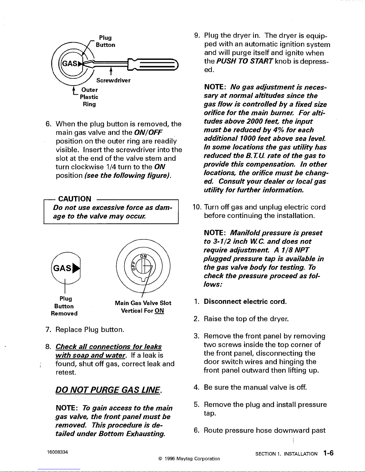
No distinction has been made between the gas and electric models as long as the
components and/or service procedures are common to both. However, anything of a
unique nature between these models has been detailed and labeled as such in the
manual.
Since the dryer was designed to utilize the modular concept of assembly, the same
approach was taken in the preparation of this manual whenever possible.
The manual is printed in a loose format and is divided into sections relating to a general
group of components and/or service procedures. Each section is further subdivided to
describe a particular component or service procedure.
The subdividing of the subject matter plus the loose leaf form will facilitate the updating
of the manual as new or revised components are added or new models are introduced.
Each page of the manual will be identified in the lower right-hand corner, and as new or
revised pages are published, the manual can easily be updated by following the filing
instructions on the cover letter of the supplement.
This service manual is a valuable tool and care should be taken to keep it up to date by
prompt and proper filing of subsequent pages as they are used.
MODELS COVERED IN THIS MANUAL:
PYE2000AY*
PYG2000AW*
HYE3657*
HYE3658*
PYET344*
HYE3460*
PYET444*
DLE/DLG231
PYE/PYG2300
PYE/PYG3200
PYE/PYG3300
PYE/PYG4500
PYE/PYG4557
PYE/PYG4558
16023116
INTRODUCTION i

16023116
INTRODUCTION ii
© 1996 Maytag Corporation

Contents
SECTION 1. INSTALLATION .......................................................................................... 1-1
INSTALLATION REQUIREMENT ........................................................................................ 1-1
Dryer Location (All Models) ........................................................................................... 1-1
Dryer Location (Gas Models Only) ................................................................................ 1-1
Gas Connection Requirements ..................................................................................... 1-1
Electrical Requirements (Gas Models) .......................................................................... 1-2
Electrical Requirements (Electric Models) ..................................................................... 1-2
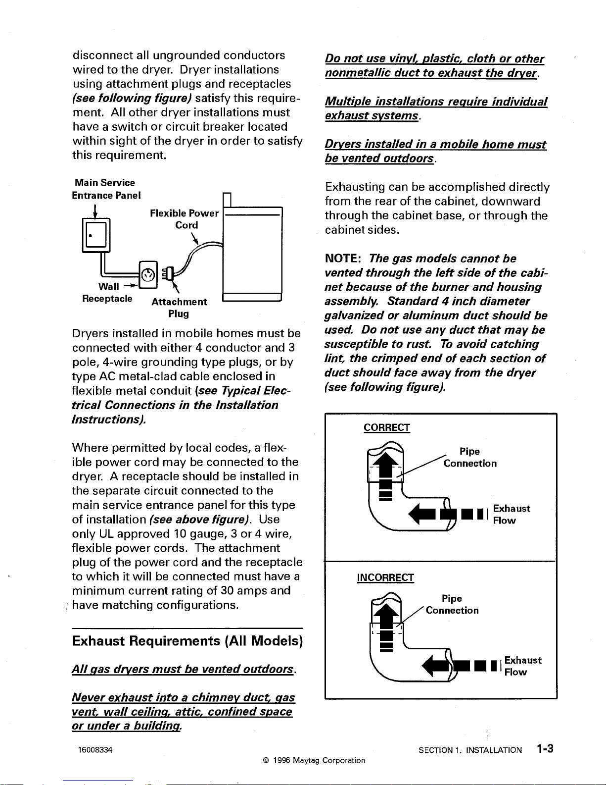
Exhaust Requirements (All Models) ............................................................................... 1-3
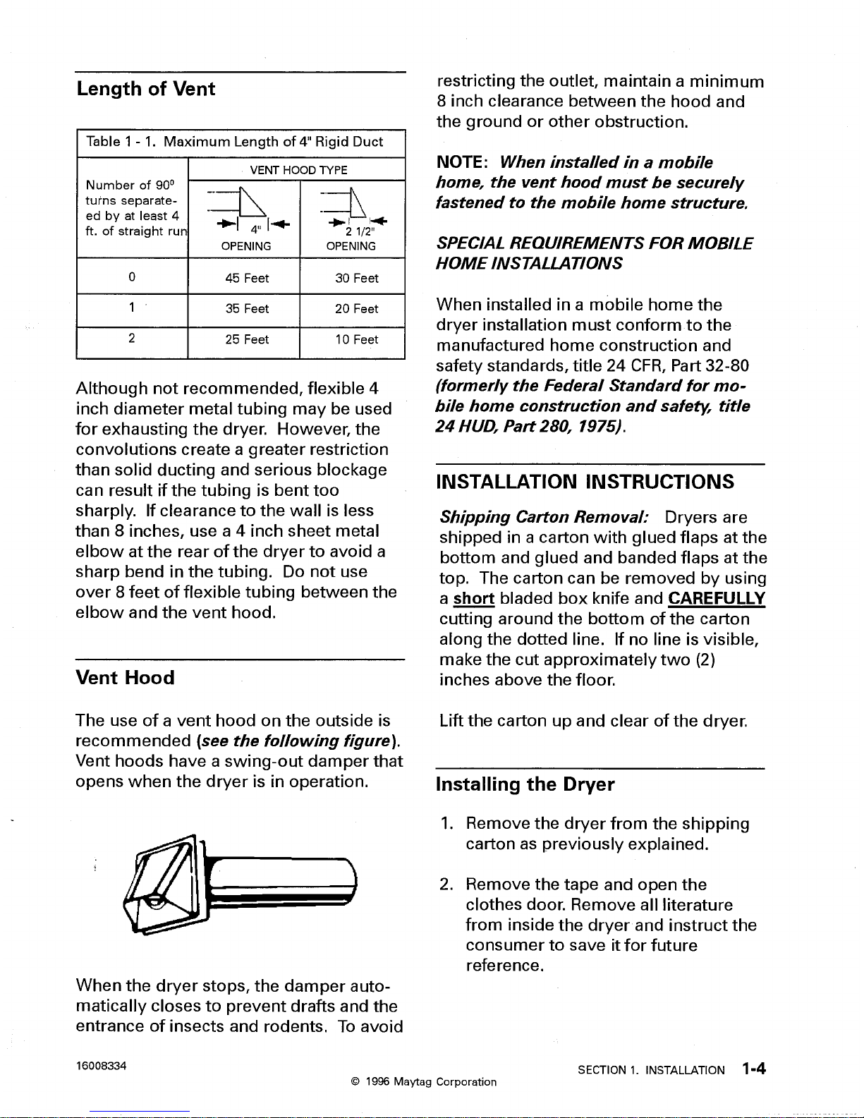
Length of Vent............................................................................................................... 1-4
Vent Hood .................................................................................................................... 1-4
INSTALLATION INSTRUCTIONS ........................................................................................ 1-4
Installing the Dryer ......................................................................................................... 1-4
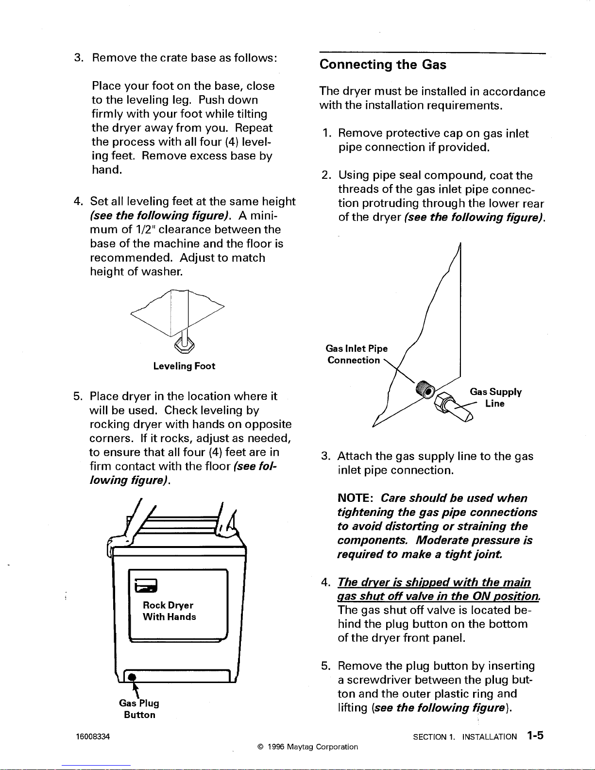
Connecting the Gas ...................................................................................................... 1-5
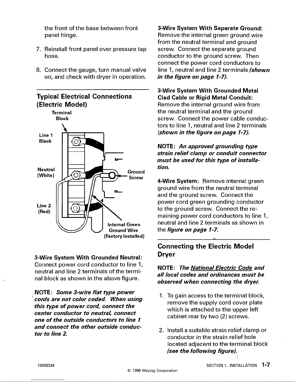
Typical Electrical Connections (Electric Model) ............................................................. 1-7
Connecting the Electric Model Dryer ............................................................................. 1-7
Exhausting the Dryer ..................................................................................................... 1-8
Leveling the Dryer ....................................................................................................... 1-10
SECTION 2. OPERATION............................................................................................... 2-1
DRYER OPERATION OVERVIEW .................................................................................... 2-1
OPERATING INSTRUCTIONS ............................................................................................ 2-1
Opening the Door ......................................................................................................... 2-1
Lint Screen ................................................................................................................... 2-2
Controls ....................................................................................................................... 2-2
Cycle Selector ............................................................................................................. 2-2
Cycles ......................................................................................................................... 2-2
Special Options ........................................................................................................... 2-3
OPERATION TEST ........................................................................................................... 2-3
SECTION 3. CABINET ASSEMBLY COMPONENTS .................................................... 3-1
CABINET AND BASE ASSEMBLY ................................................................................... 3-1
TOP ASSEMBLY .............................................................................................................. 3-1
FRONT PANEL ASSEMBLY ............................................................................................. 3-3
COLLECTOR DUCT ASSEMBLY ..................................................................................... 3-4
DOOR ASSEMBLY ............................................................................................................ 3-4
DOOR SEAL ..................................................................................................................... 3-6
SECTION 4. CYLINDER ASSEMBLY AND RELATED PARTS ..................................... 4-1
CYLINDER ASSEMBLY ..................................................................................................... 4-1
Cylinder Belt ................................................................................................................. 4-2
CYLINDER SUPPORT ROLLERS AND GLIDE .................................................................. 4-3
REAR ROLLER SUPPORT ASSEMBLIES ........................................................................ 4-3
GLIDE ASSEMBLY ............................................................................................................ 4-4
FRONT AND REAR SEALS .............................................................................................. 4-5
16023116
CONTENTS iii
© 1996 Maytag Corporation

SECTION 5. BLOWER AND DRIVE MODULE .............................................................. 5-1
BLOWER ASSEMBLY ....................................................................................................... 5-2
COVER ASSEMBLY .......................................................................................................... 5-2
BLOWER WHEEL ............................................................................................................. 5-3
HOUSING ASSEMBLY ....................................................................................................... 5-3
IDLER ASSEMBLY ............................................................................................................ 5-4
MOTOR AND PULLEY ASSEMBLY ................................................................................... 5-4
SECTION 6. HEAT SOURCE AND RELATED PARTS ................................................... 6-1
HEATER ASSEMBLY ........................................................................................................ 6-2
CONTROL AND BURNER ASSEMBLY .............................................................................. 6-3
SILICON CARBIDE IGNITION SYSTEM ............................................................................. 6-4
Gas Control Valve ......................................................................................................... 6-5
Holding Coil .................................................................................................................. 6-5
Booster Coil ................................................................................................................. 6-5
Second Coil.................................................................................................................. 6-5
Flame Sensor ............................................................................................................... 6-5
Silicon Carbide Igniter .................................................................................................. 6-6
CIRCUIT OPERATION ....................................................................................................... 6-6
Normal Ignition - Start .................................................................................................... 6-6
Normal Ignition .............................................................................................................. 6-6
SAFETY FEATURES ......................................................................................................... 6-7
Power Interruption ......................................................................................................... 6-7
Ignition Failure .............................................................................................................. 6-7
Flame Failure ............................................................................................................... 6-8
PART REMOVAL AND REPLACEMENT ........................................................................... 6-8
BULKHEAD ASSEMBLY ................................................................................................... 6-9
Inlet Duct (Gas Model) or Heater Housing (Electric) ..................................................... 6-10
High Limit Thermostat ................................................................................................. 6-10
Thermal Fuse.............................................................................................................. 6-10
Cylinder Light Lens ..................................................................................................... 6-10
Terminal Block (Electric Model) ................................................................................... 6-10
Rear Seal ................................................................................................................... 6-10
Rear Support Rollers .................................................................................................. 6-10
BULKHEAD ASSEMBLY REMOVAL.......................................................................... 6-10
SECTION 7. BACKGUARD ASSEMBLY ........................................................................ 7-1
SECTION 8. ELECTRICAL COMPONENTS AND TESTING ......................................... 8-1
TIMER ................................................................................................................................ 8-1
Resistor (Electric Models Only) ..................................................................................... 8-1
Timer Access and/or Removal ...................................................................................... 8-1
Timer Sequence Chart .................................................................................................. 8-1
Contact Functions ......................................................................................................... 8-1
WRINKLE RELEASE SWITCH .......................................................................................... 8-2
TEMPERATURE SELECTOR SWITCH ............................................................................. 8-2
16023116
CONTENTS iv
© 1996 Maytag Corporation

DOOR SWITCH ................................................................................................................. 8-7
SILICON CARBIDE IGNITION SYSTEM ............................................................................. 8-7
No Igniter Glow ............................................................................................................. 8-8
Igniter Glows - No Gas Ignition ...................................................................................... 8-8
Gas Ignites - Flame Goes Out ....................................................................................... 8-8
HEATER ELEMENT ASSEMBLY ....................................................................................... 8-8
THERMOSTATS ................................................................................................................ 8-8
Control Thermostat ....................................................................................................... 8-9
High Limit Thermostat ................................................................................................... 8-9
Inlet Air Control Thermostat (Gas Models Only) .............................................................. 8-9
THERMAL FUSE ............................................................................................................. 8-10
MOTOR ........................................................................................................................... 8-11
Overload Protector Switch .......................................................................................... 8-11
Motor Switch ............................................................................................................... 8-12
SECTION 9. WIRING AND SCHEMATICS ...................................................................... 9-1
DLE231* ...................................................................................................................... 9-1
DLG231* ...................................................................................................................... 9-3
PYE2300*, HYE2460*, PYET244* ................................................................................ 9-5
PYG2300* .................................................................................................................... 9-7
PYE3200*/3300* .......................................................................................................... 9-9
PYG3200*/3300* ........................................................................................................ 9-11
PYE4500*/4557*/4558* .............................................................................................. 9-13
PYG4500*/4557*/4558* .............................................................................................. 9-15
HYE3657*, HYE3658*, PYET344* .............................................................................. 9-17
HYE3460* .................................................................................................................. 9-19
PYET444* .................................................................................................................. 9-21
16023116
CONTENTS v
© 1996 Maytag Corporation

16023116
© 1996 Maytag Corporation
CONTENTS vi

© 1996 Maytag Corporation
SAFETY NOTES
This manual is designed and intended for the experienced service technician; one who
possesses a level of mechanical and electrical knowledge commonly recognized as
acceptable in the appliance service field and who is familiar with the construction and
operation of Maytag serviced products. Maytag and/or the product manufacturer assume no liability for the use or interpretation of this service manual by any other persons.
To reduce the possibility of personal injury and/or property damage, it is necessary to
observe certain safety precautions during the servicing of electrical or gas model dryers. The following are some, but not necessarily all, of the precautions which should be
followed:
1. Disconnect electrical supply before servicing machine.
2. If electricity is required for a test; first, make any connections or adjustments
required for the test; second, reconnect the electrical supply; third, perform the
test. If additional service is required, disconnect the electrical supply before con-
tinuing.
3. On base model dryers, do not disturb a gas carrying component or connection
until the gas supply to the dryer is shut off. Following the repair, make certain all
gas connections are properly secured by testing for gas leaks with a bubble or
soap solution.
WARNING: DO NOT use a flame to test for gas leaks.
4. Never attempt to bypass or otherwise interfere with the proper operation of any
device engineered into the product.
5. Ground wires, usually green in color, should never be used as current carrying
conductors.
6. Use only authorized factory replacement parts.
7. Prior to reconnecting the electrical supply to the dryer after servicing, ensure that:
• All electrical connections within the dryer are correctly and securely attached.
• All electrical leads are properly protected from sharp edges, high temperature
components and moving parts.
16023116
SAFETY NOTES vii

• Any uninsulated current carrying metal parts have adequate spacing from
all non-current carrying metal parts.
• All electrical grounds, both internal and external to the dryer, are re-established
and securely connected.
8. Following the servicing and prior to operating the dryer, properly and securely
reassemble all panels.
16023116
SAFETY NOTES viii
© 1996 Maytag Corporation

© 1996 Maytag Corporation
SPECIFICATIONS
DIMENSIONS ALL MODELS
Height 44"
Width 27"
Depth 27"
Door Clearance Required 53 1/2"
ELECTRICAL ELECTRIC MODEL GAS MODEL
Power Supply 240V 120V
Motor 420W 420W
Heating Element 4750W
Circuit No. 10 AWG Copper No. 12 AWG Copper
Fuse Size 30A 15A
GAS REQUIREMENTS GAS MODEL
Rated Input 18,000 BTU/Hr.
Type Natural
Inlet Size 3/8" - 18 N.S.
Ignition Type Intermittent
MISCELLANEOUS ALL MODELS
Air Flow 175 C.F.M.
Cylinder Rotation 49 R.P.M.
Cylinder Volume 7 C.F.
COMPONENT FINISH ALL MODELS
Top Assembly Enameled Steel
Cabinet Assembly Enameled Steel
Front Panel Enameled Steel
Cylinder Assembly Primered Steel
SPECIAL TOOLS REQUIRED
No. T-10 Torx Bit
No. T-15 Torx Bit
No. T-20 Torx Bit
16023116
SPECIFICATIONS ix

16023116
SPECIFICATIONS x
© 1996 Maytag Corporation

 Loading...