

Page 1
Maytag
111990"
Automatic
Dryers
Service
Manual
16000132
Issued
1990
Revised
2/98
Page 2

Page 3
Contents
SECTION 1. ELECTRICAL TEST EQUIPMENT "
1-1
APPLIANCE TEST METER
1-1
CLAMP-ON AMMETER
'.
. . . . . . . . . . . . . . . . . . . . . . .
..
1-3
MOTOR TEST CORD 1-4
VOLTAGE CHECKS 1-5
TEMPERATURE READINGS RANGE (50°F.
to
300°F.) 1-6
SECTION 2. ELECTRICAL - MECHANICAL TROUBLESHOOTING
2-1
WILL NOT RUN
2-1
WILL NOT DRY ' 2-2
WILL NOT SHUT OFF
,...............................
2-2
MISCELLANEOUS
,...................................
2-6
MICROPROCESSOR
BOARD
CONTROL MODELS 2-7
DRYER (MICROPROCESSOR BOARD CONTROL)
2-11
FAULT CODE 2-15
SECTION 3. SERVICE PROCEDURES
3-1
ACCESS
TO
CONTROL PANEL COMPONENTS
3-1
CONTROL PANEL ASSEMBLY COMPONENTS
3-1
MICROPROCESSOR
BOARD
CONTROL 3-10
FRONT PANEL AND COMPONENTS 3-13
TUMBLER AND RELATED COMPONENTS 3-17
THERMOSTATS 3-24
BLOWER
3··27
DRIVE MOTOR
AND
IDLER ASSEMBLY
,........................
3-28
HEATING ELEMENT
AND
RELATED COMPONENTS -- ELECTRIC MODELS
3-31
GAS VALVE AND RELATED COMPONENTS 3-34
CABINET AND TOP COVER
3-41
SECTION 4. PRE-INSTALLATION CONSIDERATIONS
4-1
LOCATING DRYER
4-1
EXHAUSTING 4-2
ADJUSTING
MAIN
BURNER 4-6
ELECTRICAL REQUIREMENTS 4-8
ELECTRICAL CONNECTIONS 4-10
A!?DITIONAL INFORMATION 4-12
PERSONAL SAFETY PRECAUTIONS
'.'
. .
..
4-12
SECTION 5. GENERAL INFORMATION
5-1
HEAT SOURCE
5-1
MODEL CHART 5-2
SCHEMATICS 5-3
ED/GD401 1090 Contents
Page 4

ED/GD401 1090
Contents
ii
Page 5
INTRODUCTION
This service manual is
intended
to assist
youindiagnosing
conditions
which
may
develop. Electrical
component
testingisfor
the
most part,
made
with
an
appliance
test
meter
and consists of checking
for
open
or
closed circuits. Mechanical checks
are
made
through
sight
and sound,
along
with
the
use of a clamp-on ammeter.
This
manualisdesigned
for
the
technician
whoisfamiliar
with
the
operation
and
construction
of
May
tag
products.
Information
containedinthis
manualisintended
for
use
byaqualified
service
technician,
familiar
with
proper
and
safe
procedures
to
be
followed
when
repairing
an
electrical
appliance.
All
tests
and
repairs
should
be
performed
byaqualified
service
technician
equipped
with
proper
tools
and
measuring
devices.
All
component
replacements
should
be
made
byaqualified
service
technician,
using
only
MA
yeOR
replacement
parts.
Improper
assembly
or
adjustment
may
occurifservice
or
repairisattempted
by
persons
other
than
qualified
service
technicians
orifparts
other
than
MA
yeOR
replacement
parts
are
used.
Improper
assembly
or
adjustment
can
cause
haz-
ardous
conditions.
There can
be
riskofinjury
or
electrical
shock
while
performing
services
or
repairs.
Injury
or
electrical
shock
can
be
serious
or
even
fatal.
The
first
and
most
important
stepofany
service
call istoaccurately
determine
what
the
complaint
is. This is best
accomplished
by
questioning
the
customer,
finding
out what
the
prodUct isorisn't
doing
and why
they
feel a
problem
exists.
Section 1 covers Electrical Test Equipment. This sections also
covers
general use
of
the
equipment;
an
Appliance
Test Meter, Clamp-On
Ammeter
and
Motor
Test
Cord.
Section 2
covers
Electrical-Mechanical
Troubleshooting
and a
listofpossible
com-
plaints. Find
the
complaint
which
you
feel best matches that
provided
by
the
cus-
tomer
and
turntothe
appropriate
page(s). You
will
find a
listofpossible
electrical
and mechanical
problems
for
the
complaint,
which
have been listedinthere
order
\
of:
1.
Easeinchecking.
2.
Probability.
ED/GD401 1090 INTRODUCTION Iii
Page 6
Systematically
eliminating
these
possibilities
will
allow
youtofind
and
correct
the
problem.
Section 3
covers
Service
Procedures.
This
section
will
provide
information
on
locationofcomponents,
disassembly
and/or
reassembly
procedures,
the
purpos,e
and/or
functionofthe
part
andinsome
instances
specific
checkstobe
made.
Section 4
covers
Pre-Installation
Considerations.
This
provides
information
on
location
and
exhaustingofdryer,
main
burner
adjustment,
electrical
requirements
and
connections.
Section 5
covers
General
Information.
This
section
covers
brief
specifications,
cycle
descriptions
and
schematics.
\
....
ED/GD401 1090
INTRODUCTION iv
Page 7
SECTION 1. ELECTRICAL TEST EQUIPMENT
The
equipment
required
to
service
May
tag
products
depends
largely
upon
the
condition
encountered.
Locating
a
malfunction
will
often
require
the
use
of
electrical
testing
equipment
such as:
•
Appliance
Test
Meter
•
Clamp-on
Ammeter
•
Motor
Test
Cord
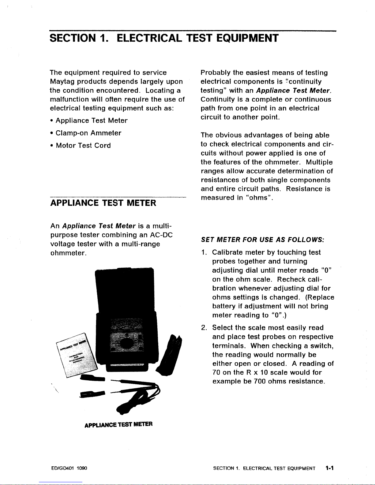
APPLIANCE TEST METER
Probably
the
easiest
meansoftesting
electrical
components
is
~'continuity
testing"
with an
Appliance
Test
Meter.
Continuity
is a
complete
or
continuous
path
from
one
point
in an
electrical
circuittoanother
point.
The
obvious
advantagesofbeing
able
to
check electrical
components
and
cir-
cuits
without
power
applied
is one
of
the
featuresofthe
ohmmeter.
Multiple
ranges
allow
accurate
determination
of
resistancesofboth
single
components
and
entire
circuit
paths. Resistance is
measuredin"ohms".
An
Appliance
Test
Meter
is a
multi-
purpose
tester
combining
an AC-DC
voltage
tester
withamulti-range
ohmmeter.
\
SF
2
APPLIANCE
TEST
METER
SET METER FOR USE
AS
FOLLOWS:
1.
Calibrate
meter
by
touching
test
probes
together
and
turning
adjusting
dial
until
meter
reads
"0"
on
the
ohm
scale. Recheck
cali-
bration
whenever
adjusting
dial
for
ohms
settingsischanged. (Replace
battery
if
adjustment
will
not
bring
meter
reading
to
"0".)
2.
Select
the
scale
most
easily
read
and place test
probes
on respective
terminals.
When checking a switch,
the
reading
would
normally
be
either
open
or
closed. A
reading
of
70 on
the
R x 10 scale
would
for
example
be 700
ohms
resistance.
ED/GD401 1090
SECTION1.ELECTRICAL TEST EQUIPMENT 1-1
Page 8
~f~
~.,~"]
Q
CAUTION
---------------,
Always
be
sure
the
power
has been
disconnected
before
making
resist-
ance
measurements.
Failuretodo
so
will
resultindamagetoyour
meter! Internal
batteries
provide
all
the
power
needed to make resist-
ance checks. They
should
be
checked at least once a
year
and
replaced as needed.
For
the
most
part, we
will
only
be
con-
cerned
with
continuity.
Is
there
a path
or
not? References
are
made
between
a
"closed"
(continuity)
reading
and an
"open"
(no
continuity)
reading.
One
note,
when
you
get an
"open"
reading,
tryahigher
resistance
range
(setting).
A
very
high
resistance
appea~s
as an
"open"
on
the
lower
ranges.
For
best
accuracy
alw~ys
"re-zero"
meter
when
changing
ranges
and/or
the
physical
positionofthe
meter.
Continuity
testing,
as
related
to an elec-
\
tricarcomponent,
is
the
checkofa
part
for
an
"open"
or
"closed"
circuit.
Electrical
components
fall into
two
general
categories.
1.
Loads-
Devices
that
use
or
consume
electricity:
Examples
ED/GD401 1090
would
include
drive
motor,
heating
elements, lamps,
timer
and
solenoid
coils.
2.
Switches
- Devices
that
control
the
supplyofelectricity
to the load
or
loads
in a
circuit.
Examples
include
door
switches,
timer
contacts,
selector
switch and
relay
contacts.
Continuity
testof"load"
devices
will
show
varying
levelsofresistance
from
very
low
for
some
transformer
and
motor
windingstovery
high
for
some
timer
motors
and
components
on elec-
tronic
control
boards.
Usually
it is
more
importanttoknowifthere
is a
path
for
current
.flow
throughadevice
(continuity)
thantoknow
the
exact
resistance (ohms)
of
the
device.
Continuity
testsofswitches
will
show
virtually
no resistance, even
low
values
indicates
burned
or
dirty
contacts in a
switch.
Continuity
testingisa
processofelimi-
nating
those
electrical
components
involved
in a
given
functionofthe
appliance,
until
the
inoperative
part
is
found.
By
reviewing
the
listofpossible
electrical
problems
underagiven
con-
dition,
and
then
performing
appropriate
continuity
checks
on
the
parts
involved,
you
should
be
able
to locate
the
elec-
trical
component
whichisinoperative.
When checking
components
or
circuit
paths
for
continuity,
external
wiring
should
be
disconnectedtoeliminate
false
readings
through
external
paths.
Isolate what
you
wanttotest.
The
following
shows
typical
resistance
values
for
someofthe
components
found
on
May
tag
dryers.
Heating
Element
-- 10.23
ohms.
SECTION1.ELECTRICAL TEST EQUIPMENT 1-2
Page 9
Gas
Valve
Disconnect
radiant
sensor
and
igniter
wires.
Measure
across
igniter
wires
or
igniter
plug
from
valvetoget a
resist-
ance
valueof-- 425-450
ohms.
Measure
across
sensor
wires
to get a
resistance
of
-- 450-475
ohms.
Drive
Motor
Red
terminal
to
Gray
terminal
-- 1.5
ohms.
In
order
to
measure
the
individual
windings
the
red
and
gray
wires
will
havetobe
pulled
offofthe
start switch.
Run
winding
only
-- 2.25
ohms.
Start Winding
only
-- 3
ohms.
Glow
Bar
Igniter
Becauseofthe
make-upofthe
igniter,
the resistance
will
vary
overarather
wide
range. Values
from
180
ohms
to
400
ohms
would
be
typical
with
an
igniteratroom
temperature.
These
values
are
provided
so
that
you
may
have
an
ideaofthe
resistance
that
you
can see in
testing.
These resist-
ances
are
not
meanttobe used as the
exact
valuestodetermine
whether
a
t;omponent
should
be replaced. They
\
are
provided
so
that
you
may
have
an
ideaofthe
resistance
that
you
can see
in
testing
components.
EDIGD401 1090
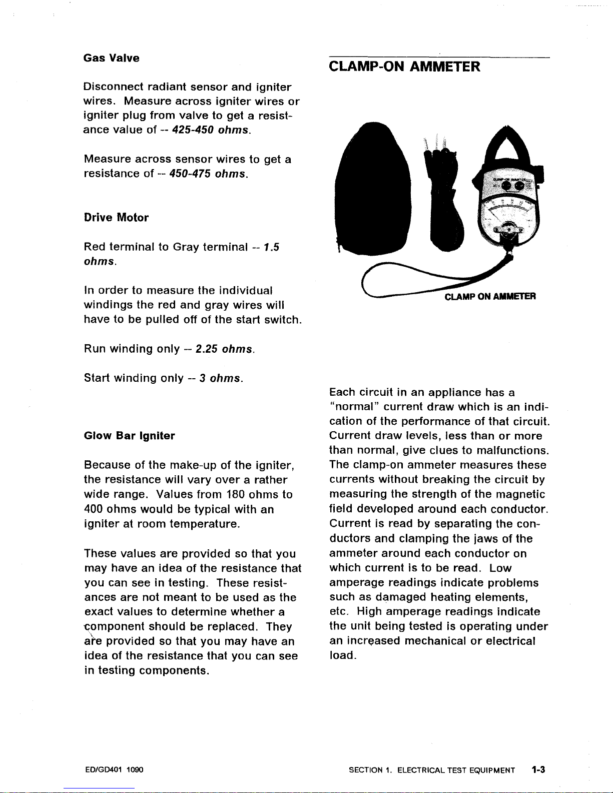
CLAMP-ON
AMMETER
Each
circuitinan
appliance
has a
"normal"
current
draw
which
is an
indi-
cationofthe
performanceofthat
circuit.
Current
draw
levels, less
than
or
more
than
normal,
give
cluestomalfunctions.
The clamp-on
ammeter
measures
these
currents
without
breaking
the
circuit
by
measuring
the
strengthofthe
magnetic
field
developed
around
each
conductor.
Current
is read
by
separating
the
con-
ductors
and
clamping
the
jawsofthe
ammeter
around
each
conductor
on
which
currentisto
be read.
Low
amperage
readings
indicate
problems
such as
damaged
heating
elements,
etc.
High
amperage
readings
indicate
the
unit
being
tested is
operating
under
an
increased
mechanicalorelectrical
load.
SECTION1.ELECTRICAL TEST EQUIPMENT
1·3
Page 10
Note:
Overloads
onacircuit
breaker
or
fuse can be
tracedtothe
product
being
tested
or
the
circuit
breaker
(or
fuse) by
checking
the
product's
current
draw.Ifthe
amperage
reading
is less
than
the
breaker
reading,
the
breaker
or
fuse
box
is at fault.
USE
OF
AMMETER
ON
DRYER
There
are
two
currentsofconcern
to
us
in an
electric
dryer;
the
heating
element
current
and
the
drive
motor
current.
These
currents
can be meas-
ured
by useofa
"split
line
cord"
exten-
sion
for
the
dryer
cord
or
by
attaching
the
ammetertothe
respective
power
line
wiresatthe
dryer
terminal
block.
Current
measured
should
be
21
amps
on
the
heating
element
sideofthe
line,
24
amps
on
the
drive
motor
sideofthe
line
and4amps
on
the
center
or
neutral
line.
A
\".
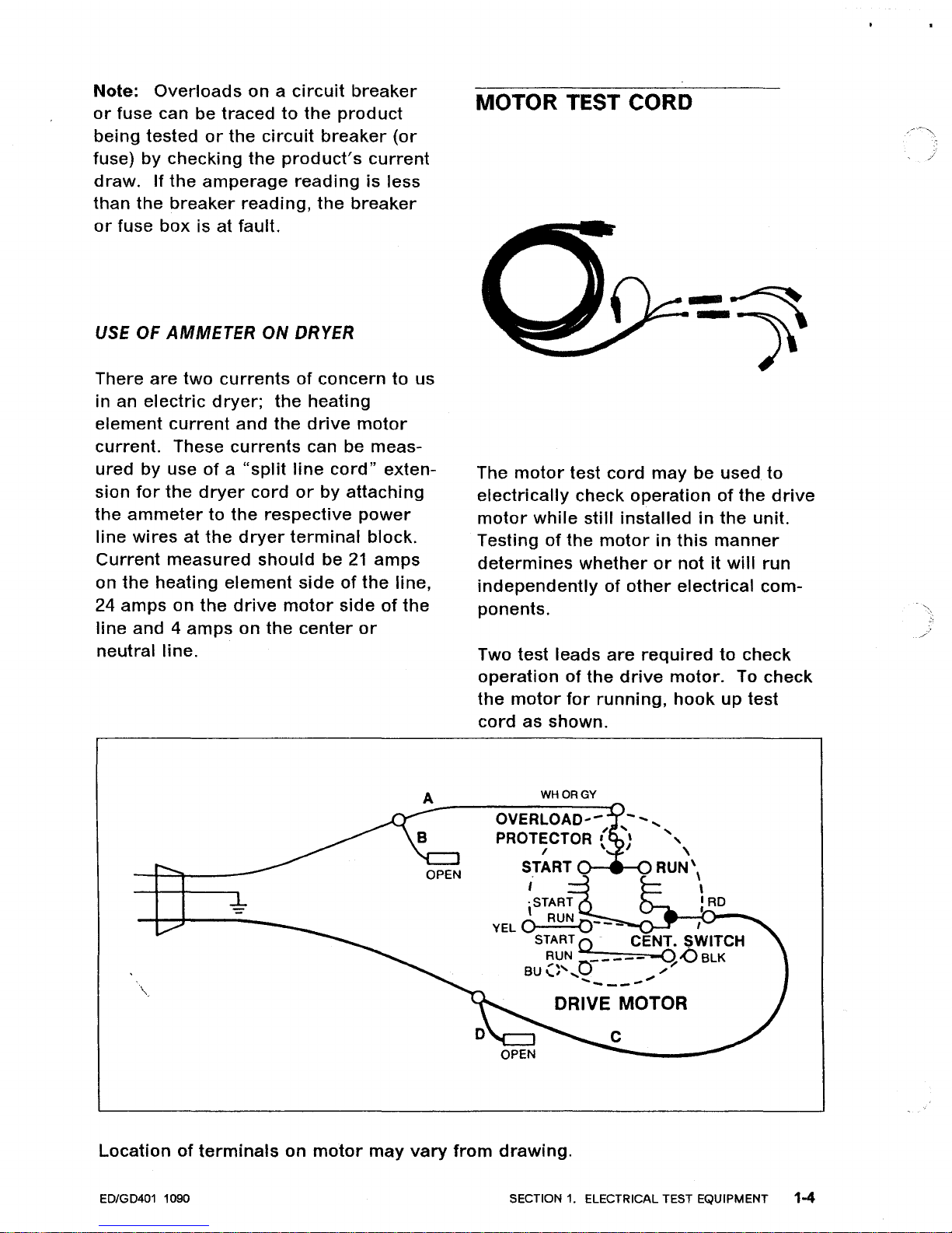
MOTOR TEST CORD
The
motor
test
cord
may
be used.
to
electrically
check
operationofthe
drive
motor
while
still
installedinthe
unit.
Testing
of
the
motorinthis
manner
determines
whether
or
notitwill
run
independently
of
other
electrical
com-
ponents.
Two test
leads
are
required
to
check
operationofthe
drive
motor.
To
check
the
motor
for
running,
hook
up
test
cord
as
shown.
WHORGY
OVERLOAD'-
,
PROTECTOR ( "
, \
START
RUN'
\
I \
,START
: AD
YEL
0 RUN
0---
I
START Q . CENT. SWITCH
~~N
0-----
-q-oBLK
BU
....
,',
...
/
..........
__
....
DRIVE MOTOR
Locationofterminals
on
motor
may
vary
from
drawing.
ED/GD401 1090 SECTION
1.
ELECTRICAL TEST EQUIPMENT 1-4
Page 11
CHECKING
HEAT
CONTACTS,
MOTOR
CENTRIFUGAL
SWITCH
1.
Disconnect
dryer
power
source.
2.
Gain accesstomotor
and
remove
blue
and
black
leads
from
motor
switch.
3. Use
eitherofthe
following
test
methods
using
appropriate
caution.
A.
Live
test
-- USE
CAUTION
1.
Usingadouble
insulated
spade
con-
nector,
connect
blue
and
black
wires
removed
from
motor
switch.
2. Reconnect
dryer
to
power
and
set
for
heat cycle.
3. Start
dryer,ifheat is
produced,
replace
motor
switch
on
motor.
If
no heat,
continue
additional
circuit
checks.
B.
Continuity
Check
(Insulate
wires
removed
from
motor
sWitch.)
1.
Using
clip
adapters,
attach
meter
probestothe
blue
and
black
motor
switch
terminals.
2.
Arrange
probe
leads
away
from
any
moving
parts
and
set
meter
on
RX1
range.
3.
Reconnect
dryer
to
power
source
and
start
dryer,
continuity
on
meter
indicates
good
switch. No
conti-
nuity,
replace
motor
switch
or
motor.
4.
Open
door
to
stop
dryer.
When
\
motor
stops,
motor
switch
contacts
must
open,ifnot
replace
switch
or
motor.
ED/GD401 1090
VOLTAGE CHECKS
For
the
most part
these
checks
will
consistoftaking
readingsatthe
wall
receptacleinorder
to
delermine
the
availability
of
voltagetothe
product.
Voltage checks on
individual
compo-
nentsofa
product
are
not
recom-
mended
duetothe
possibility
of
electrical
shock.
Component
part
testing
is best
accomplished
through
continuity
checks
with
an
Appliance
Test
Meter.
Note:
Useofthe
meter
on
voltage
higher
than
the
indicated
range
may
cause
permanent
damagetothe
meter.
To
prevent
damage,
first
select
highest
range
for
readings
which
fall
within
the
lower
scale.
SET UP METER FOR USE
AS
FOLLOWS:
1.
Turn
selector
knobtodesired
meter
function
and
appropriate
range.
2.
Plug
black
lead
into
socket
marked
-
(negative).
3. Plug red
lead
into
socket
marked
+
(positive).
4.
Place test
leads
into
receptacle
in
order
to
determine
voltage
avail-
able.
SECTION1.ELECTRICAL TEST EQUIPMENT 1-5
Page 12
TEMPERATURE READINGS
RANGE
(50°F. to 300°F.)
Air
temperature
readings
can be taken
at
the
lint
filter
by
removing
the
filter
and
placing
the
accessory
temperature
probe
(Part NO. 38562)
directlyinthe
lint
filter
opening.
Cyclingofthe
ther-
mostats can
actually
be
observed
as
can the
temperatureofthe
exhausted
air.
SET UP METER FOR USE
AS
FOLLOWS:
1.
Turn
selector
knob
to TEMP.
2.
Insert
black
negative
leadoftemper-
ature
probe
into
socket
marked
-
(negative).
3.
Insert red
positive
leadoftemper-
ature
probe
into
socket
marked
+
(positive).
4.
To
calibrate
meter,
touch
black
plug
from
red
positive
leadtoblack
nega-
tive
lead
and
turn
calibration
dial
until
needle
aligns
with
CAL.
5.
Probeisreadytouse -- read
blue
scale
on
meter
face
marked
TEMP.
ED/GD401 1090
SECTION
1.
ELECTRICAL TEST EQUIPMENT 1-6
Page 13
SECTION
2.
ELECTRICAL - MECHANICAL
TROUBLESHOOTING
WILL NOT RUN
Dryer
won't
start
or
run.
•
All
wires
are
hooked
uptotheir
corre-
sponding
terminals.
•
Dryerisplugged
in.
•
Blown
fuseorcircuit
breaker.
•
Door
switch.
•
Push-to-start
switch.
•
Timer.
•
Drive
motor.
•
Thermal
fuse.
Drive
motor
runs--drum
won't
turn.
•
Belt
offorbroken.
•
Motor
pulley
loose
or
off.
•
Idler
tension
spring.
•
Idler
pulley.
Dryer
runsafew
minutes
and
then
stops
--Motor
overload
protector
opens.
•
Lint
build-up
around
drive
motor.
•
Low
voltage.
•
Blower
impeller
blocked.
e,
Drive
motor.
\\.
Dryer
blows
fuses
or
trips
circuit
breaker.
Electric
Models
• The
amperage
readings
areat240
volts.
One
line
will
be
24
amps
and
the
other
line
will
be
21
amps.
The
neutral
line
will
beat4
amps.
If
you
have
the
above
amperage
readings,
the
problemisnot
the
dryer.
Check
the
fuse
box,
circuit
breaker
or
house
wiring.
•
Shorted
heating
element.
•
Incorrect
wiring
orawire
shorting
to
ground.
•
Drive
motor.
Gas
Models
•
During
ignition
the
dryer
will
draw
7
amps.
With
the
burner
on,
the
dryer
will
draw
4.5
amps.
If
the
dryer
is
drawing
the
above
amperage
and
the
fuse
blows,
the
problemisnot
the
dryer.
Check
the
fuse
box,
circuit
breaker
or
house
wiring.
•
Igniter.
•
Incorrect
wiring
orawire
shorting
to
ground.
•
Drive
motor.
CAUTION
---------------------------,
Always
disconnect
power
supply
before
making
any
continuity
checks
or
resist-
ance
readings.
ED/GD401 1090
SECTION2.ELECTRICAL - MECHANICAL TROUBLESHOOTING
2.,.1
Page 14
WILL NOT DRY
Dryer
won't
heat
(motor
runs).
ELECTRIC MODELS
•
Blown
fuseortripped
circuit
breaker.
• Open
heating
element.
•
Hi-limit
thermostat.
•
Regulating
thermostat.
•
Temperature
selector
switch.
• Timer.
• Cycle
selector
switch (where used).
•
Drive
motor
start
switch.
Improper
Drying--Clothes
Wrinkled
--
Harsh
-- Taking
too
long
•
Lint
filter
is clean.
• Restriction in exhaust.
• Exhaust
hood
door
stuck.
• Exhaust
too
long.
•
Poor
make-up
air.
•
Incorrect
drum
speed.
Adjust
motor
pulley
or
wrong
motor
pulley.
•
Blower
impeller
bound.
•
Be
sure
elementorgas
valve
cycles
on and off.
•
Shorted
heating
element-electric
dryers
only.
•
Customer
ove'tloading
dryer.
• Check
clothing
labels
for
fabric
content.
WILL NOT SHUT OFF
Time
Dry
Models
•
Timer
motor.
• Timer.
AUTO DRY MODELS
• Set
timer
for
time
dry.
Check
voltage
across
timer
motor.Iftimer
will
not
advance, replace
timer.
• When
valve
or
element
cycles off,
should
have
powertotimer
motor,
if
not,
proceed
with
next
check.
•
Dryer
cycling
on
hi-limit
thermostat.
Check
following.
•
Lint
filter
clean.
•
Restriction
in exhaust.
• Exhaust
hood
door
stuck.
• Exhaust
too
long.
•
Regulating
thermostat.
•
Customerisoverloading
dryer.
ELECTRONIC CONTROL MODELS
The
electronic
control
and
timer
are
usedtocomplete
the
drying
cycle
and
cool-down
period
for
these
dryer
models.
The
dryer
starts
out
with
the
drive
motor
running,
the
timer
motor
running,
the
heat
cycling
and
the
elec-
tronic
control
disabled.
As
the
timer
advancestoa
certain
pointinthe
cycle,
CAUTION
-------------------------,
Always
disconnect
power
supply
before
making
any
continuity
checks
or
resist-
ance
readings.
ED/GD401 1090
SECTION
2.
ELECTRICAL - MECHANICAL TROUBLESHOOTING 2-2
Page 15
the
electronic
control
becomes
opera-
tional
as cam
number
two
opens. A
short
time
later,
the
timer
motorisde-
energized
when
cam
number
one
for
the
timer
motor
opens.
It is
during
this
stall
period
that
the
electronic
control
system uses
the
wet
clothes
falling
across
the
sensorinthe
drum
to
dis-
charge
the
capacitor
and
keep
the
dryer
running.
There
are
three
dryness
levels;
More
Dry,
Normal
Dry
and
Less Dry. These
dryness
levels
have been
accomplished
by
placing
resistors
on
the
electronic
control
(printed
circuit
board)
and
routing
the
bypass
wiring
accordingly.
The levelofresistanceinthe
circuit
,
determined
by
the
dryness
level
selected, affects
the
charge-up
rate
of
the
capacitor
and
accomplishes
the
desired
dryness
level.
As
the
clothes
get
dry,
the
capacitorisabletobuild
up a
chargetoa
point
where
the
neon
bulb
fires,
thus
triggering
the
gate on a
SCR. When
this
happens,acircuit
is
made
through
the
SCR,
energizing
the
coilinthe
relay. This
takes
onlyasplit
second
and
the
relay's
coilisthen
held
energized
through
a setofcontacts
in
the
relay.
Also,
when
the
coilinthe
relayisener-
gized,
the
timer
motorisactivated
through
another
setofcontactsinthe
relay. The
timer
advances
and
opens
cam
number
three
for
the
heater
and
the
dryer
beginsatimer
controlled
CAUTION
cool-down
period.
The
amountofcool-
down
time
will
depend
upon
the
cycle
selected:
Regular
- 6
minutes,
Permanent-Press
- 13
minutes
and
Permanent-Press
with
Press
Care
- 33
minutes.
NOTE:
These
times
are
approximate.
The
timer
then
advances
to
where
cam
number
1A opens,
de-
energizing
the
drive
motor
and
the
cycle
ends.
TROUBLESHOOTING
When
the
dryer
does
not
go
into
cool-
down
and
shut
off with
dry
clothes,
you
needtoknow
whether
you
have a
control
problem
orasensor
problem.
Troubleshooting
the
electronic
control
is
made
easierifwe
break
the
circuit
down
into
parts. We can
separate
the
two
parts
by
disconnecting
the
W-BU
wireinthe
control
panel at
the
plastic
coupler.
The
upper
part
contains
the
electronic
control
assembly
which
con-
sistsofthe
edgeboard
connector
assembly,
printed
circuit
board
assembly
and
relay. The
lower
part
consistsofthe
sensor
assembly
located
on
the
tumbler
front
bulkhead.
Separating
the
two
areas
by
pulling
the
wires
apartatthe
coupler
will
show
where
the
problemislocated.Ifthe
dryerisstarted
without
any
clothes
in
the
drum
and
shuts
offinabout
20
minutes
without
the
sensor
circuit
hooked
up,
then
the
sensor
must
be
keeping
the
dryer
from
shutting
off.
Always
disconnect
power
supply
before
making
any
continuity
checks
or
resist-
ance
readings.
ED/GD401 1090 SECTION
2.
ELECTRICAL - MECHANICAL TROUBLESHOOTING
2-3
Page 16

NOTE:
This
amountoftimeisfor
Regular
Fabrics
onaLess
Dry
setting.
A
settingofNormal
Dry
or
More
Dry
will
add
more
time
before
the
dryer
shuts
off. If
the
dryer
does
not
shut
off,
then
the
problem
is in
the
electronic
control
assembly.
Sensor
Assembly
1.
Disconnect
power
supply.
2.
Remove
front
panel.
3.
Remove
wires
goingtothe
sensor
bars.
4.
Check
with
ohmmeter
to
make
sure
there
is NO
continuity
across
the
sensor
bars. If
you
have
continuity
across
the
sensor
bars
the
capacitor
cannot
buildacharge,itwill
contin-
ually
bleed
off.
CAUTION
Always
disconnect
power
supply
before
making
continuity
or
resistance
checks.
5.
Checktomake
sure
the
sensor
bar
(the
one
not
connected
to
cabinet
ground)isnot
shorted
to
cabinet
ground.Ifthis
sensor
bar
has
a
leakage
pathtocabinet
ground,
the
capacitor
cannot
buildacllarge
and
will
continually
bleed
off. Use
ohmmeter
to
~heck
from
sensor
bar
to
cabinet
ground.
Electronic
Control
Assembly
If
dryer
does
not
go
into
cool-down
and
shut
off
with
the
sensor
disconnected
the
problem
isinthe
electronic
control
assembly.
While
the
dryerisrunning,
observe
the
neon
bulb
on
the
electronic
control
(printed
circuit
board).
When
the
capacitor
reaches
approximately
72
volts,
the
neon
bulb
"fires"
(flashes),
the
SCR
conducts,
the
relay
coil
is
energized
and
the
contactsinthe
relay
close.
If
neon
bulb
"FIRES"
but
timer
does
not
advance
(timer
motorisnot
ener-
gized):
1.
Check
relay
coil
for
continuity
or
resistance.
A.
Disconnect
power
supply.
B.
Remove
BK
and
BR
wires
from
relay
(refertoelectrical
wiring
diagram).
C.
Attach
meter
leads
across
these
terminals
and
complete
check.
If
checking
resistance,
you
should
see
about
2200
ohmsofresistance.
No
continuity,
replace
relay.
2.
Check
continuity
across
contacts
O-BKtoRDinrelay.
When
closed,
this
setofcontacts
is usedtokeep
the
coil
energized.
A.
Disconnect
power
supply.
B.
Remove
wires
O-BK
and
RD
from
relay.
CAUTION
--------------------------,
Always
disconnect
po~er
supply
before
making
any
continuity
checks
or
resistance
readings.
ED/GD401 1090
SECTION2.ELECTRICAL - MECHANICAL TROUBLESHOOTING 2-4
Page 17
C.
Remove
BK
wire
from
buzzer.
D.
Attach
motor
test
cordtothe
BK
wire
(removed
from
buzzer)
and
to
the
O-BK
wire
(removed
from
relay).
E.
Plug
motor
test
cord
into
outlet
(coilinrelay
should
now
be
ener-
gized).
F.
Check
for
continuity
from
ter-
minal
RD on
relaytoterminal
O-BK
on relay. No
continuity,
replace
relay.
CAUTION SHOULD
BE
EXERCISED
WHENEVER WORKING AROUND
LIVE VOLTAGE.
3.
Check
continuity
across
contacts
W-BKtoRDinrelay. When
closed,
this
setofcontactsisusedtoener-
gize
the
timer
motor
by
bringing
the
neutral
sideofthe
power
supply
through
the
relay,tothe
timer
motor.
A.
Disconnect
power
supply.
B.
Remove
wires
W-BK,
O-BK
and
RD
from
relay.
C.
Remove
BK
wire
from
buzzer.
D.
Attach
motor
test
cord
to
the
BK
wire
(removed
from
buzzer)
and
to
the
O-BK
wire
(removed
from
relay).
E.
Plug
motor
test
cord
into
outlet
(coilinrelay
should
now
be
ener-
gized).
\"-
CAUTION
F.
Check
for
continuity
from
ter-
minal
RD on
relaytoterminal
W-BK
on relay. No
continuity,
replace
relay.
4.
Replace
electronic
control
(printed
circuit
board).
If
neon
bulb
does
not
"FIRE":
1.
Check
capacitor.
A.
Disconnect
power
supply.
B.
Remove
electronic
control
(printed
circuit
board).
C. Set
ohmmetertoan
ohm
scale,
such as Rx100.
D.
Place
meter
leads
into
openings
in
the
edgeboard
connector
where
capacitor
leads
terminate.
First,
make
sure
you
have
discharged
the
capacitor
by
shorting
the
leads. Use
a
pieceofinsulated
wire
with
the
ends
stripped.
E.
Needle
should
deflecttoone
side
and
then
slowly
drop
backtozero.
F.
Failuretodeflect
the
needle
would
indicate
an
open
capacitor.
Failureofthe
needletodrop
back
would
indicateashorted
capacitor.
Replace
edgeboard
connector
assembly.
2. Replace
electronic
control
(printed
circuit
board).
Always
disconnect
power
supply
before
making
any
continuity
checks
or
resist-
ance
readings.
ED/GD401 1090 SECTION2.ELECTRICAL - MECHANICAL TROUBLESHOOTING 2-5
Page 18
MISCELLANEOUS
Dryer
noisy.
•
Thumping
sound.
Check
for
loose
drum
baffle.
•
Thumping
sound.
Rear
drum
roller(s)
worn
or
misaligned.
•
Thumping
sound.
Check
drum
for
rough
spots.
• Ticking
sound.
Loose
wire
hitting
cabinet
or
other
component.
• Ticking
sound.
Check
for
an
object
caught in
the
blower.
•
Scraping
sound.
Frontorrear
bulkhead felt seal
outofposition.
•
Scraping
sound.
Teflon
bearings
mountedtothe
front
bulkhead
worn.
• Popping
or
squealing
sound.
Check
for
a sticky
beltorfrayed
belt.
Buzzer
will
not
buzzatendofcycle.
(Auto
Dry
Models)
•
Be
sure
all
wires
are
connected
and
wired
correctly
on
the
timer,
buzzer
and
drive
motor.
• Buzzer.
•
Motor
centrifugal
switch
sticking
in
run
position.
Buzzer
stays
on
too
longorgoes
off
too
quickly.
(Auto
Dry
Models)
•
Lengthoftime
the
buzzer
stays on is
dependent
upon
the
timeittakes
the
motor
to
slow
down,
allowing
the
motor
switch to reset. The
normal
time
incrementisbetween 2
and
3
seconds.
Buzzer
will
not
buzz
during
Press
Care
Setting.
• With
dial
set on
auto
dry
permanent
press and
the
press
care
"on"
button
depressed,
the
buzzer
will
sound
at
the
endofthe
normal
14
minute
cool-
down.
After
this,
the
dryer
will
con-
tinuetotumble
clothes in cool
air
for
24
minutes.Ifbuzzer
does
not
sound,
proceed
on.
•
Buzzer
signal
on.
•
Miswired
press
care
switchortimer.
• Buzzer.
•
Timer.
Buzzer
will
not
periodically
buzz
during
permanent
press
cool
down.
• Timer.
CAUTION
---------------~---------,
Always
disconnect
power
supply
before
making
any
continuity
checksorresist-
ance
readings.
ED/GD401 1090
SECTION 2. ELECTRICAL -
MECHANICAL
TROUBLESHOOTING 2-6
Page 19
MICROPROCESSOR BOARD
CONTROL MODELS
The
microprocessor
board
receives
input
information
from
the
various
com-
ponents
involved
with
the
operation
of
the
dryer;
such as
the
dryness
sensor
and
the
thermistor.
It uses
this
infor-
mationtodetermine
the
necessary
control
for
the
completion
of
the
cycle.
One
of
the
waysitaccomplishes
this
is
through
the
useofcontrol
relays.
A
control
relay
(S.P.S.T.) is placedinthe
motor
circuit
for
both
the
gas
and
elec-
tric
dryer.
Another
relay
(S.P.S.T.) is
placed
in
the
heat
circuit
for
the
electric
dryer
only.
With
these
relays
the
microprocessor
board
is capable of
usingalow
voltage
circuittocontrol
a
high
voltage
circuit.
We can call
these
two
circuits
the
control
circuit
and
the
controlled
circuit.
NOTE: The
control
for
the
gas
dryer's
gas
valve
circuit
is
different
andiscovered
later.
The
control
circuit
for
the
drive
motor
consistsofthe
microprocessor
board
and
the
Motor
Relay's
coil. The
con-
trolled
circuit
for
the
drive
motor
con-
sists
of
the
Motor
Relay's
switch
contacts,
thermal
fuse
and
cut-off
drive
,
motor
and
door
switch. The
micro-
processor
board
starts
the
drive
motor
by
sending
24 VDCtothe
Motor
Relay's
coil. When
energized,
the
coil
creates a
magnetic
field
that
closes
the
CAUTION
switch
contactsinthe
relay
and
pro-
vides
a path
for
voltage
to
the
motor.
When
the
microprocessor
board
deter-
minesitneedstostop
the
motor,
it
removes
the
24 VDCtothe
relay's
coil.
The
switch
returnstoits
normally
open
position
and
the
path
for
voltagetothe
motorisopened.
The
control
circuit
and
controlled
circuit
for
the
heating
element
on
the
electric
dryer
operate
on
the
same
principle
as
the
motor
relay's
circuits.
When
the
microprocessor
board
wantstoener-
gize
the
heating
elementitsends
24
VDC to
the
coilinthe
Heater
Relay
and
a path
for
voltageiscompleted
through
the
switch contactstothe
heating
element.
When
the
24 VDC
are
removed
from
the
coil
the
switch
con-
tacts
open
and
the
path
for
voltage
to
the
heating
elementisopened.
TROUBLESHOOTING
When
trying
to
determine
what
is
causing
the
problem
(drive
motor
will
not
run
or
heating
element
will
not
come
on),
separate
the
two
circuits
to
isolate
the
problem
area. Start
with
the
control
circuit
(it hastofunction
before
the
controlled
circuit
will
work).
Deter-
mine
what is
involvedinthis
circuit
and
proceedtocheck
the
components.
If
these
components
are
foundtobe
func-
tioning
correctly,
focus
on
the
con-
trolled
circuit.
Determine
what
is
involved
and
proceedinchecking
the
components.
Always
disconnect
power
supply
before
making
any
continuity
checksorresist-
ance
readings.
ED/GD401 1090
SECTION
2.
ELECTRICAL -
MECHANICAL
TROUBLESHOOTING 2-7
Page 20
CONTROL
CIRCUIT
Drive
motor
will
not
run
(gas
and
elec-
tric):
1.
Disconnect
the
power
supply.
CAUTION
Always
disconnect
power
supply
before
making
continuity
or
resistance checks.
2.
Make
continuity
check
or
resistance
check on
Motor
Relay's
coil.
A.
Remove
wire
connectors
O-BK
and W-BU on
the
Motor
Relay.
B. Attach
meter
leads
across
termi-
nals
O-BK
and W-BU. You
should
see
about
470
ohmsofresistance
if
checking resistance.
C.
No
continuity,
replace
the
relay.
CAUTION:
Use
extreme
care
when
checking
voltage.
3.
Check
for
24 VDC
across
the coil on
the
Motor
Relay. To check
for
this
voltage
the
dryer
hastobe in a
program.
A. Place
meter
leads
across
wire
connectors
O-BK
and W-8U on
the
Motor
Relay (the
relay
has
two
sizes
of
terminals;
the
smaller
terminals
for
DC
and the
larger
terminals
for
AC).
\.
CAUTION
Note:
You
are
checking
DC
voltage,
set and use
meter
accordingly.
B. No voltage, suspect
the
micro-
processor,
transformer,
edgeboard
connector
AA
or
power
supply.
CONTROLLED
CIRCUIT
1.
Check
for
continuity
across
the
Motor
Relay's
switch
contacts
with
the
coil
energized.
A. Disconnect
power
supply.
B.
Remove
wire
connectors
R-BK
and
GY.
C. Attach
the
meter's
leads
across
terminals
R-BK
and
GY.
D. Connect
power
supply_
CAUTION SHOULD BE EXERCISED
WHENEVER WORKING AROUND
LIVE VOLTAGE.
E.
No
continuity
across
switch
con-
tacts
with
coil
energized,
replace
the
relay.
2.
Another
methodofchecking.
A.
Disconnect
the
power
supply.
B. Remove
and
connect
wires
R-BK
and
GY
together
(the
wires
connec-
tors
are
insulated,ajumper
will
have to be used).
_
......
,~
Always
disconnect
power
supply
before
making
any
continuity
checks
or
resistance
readings.
ED/GD401 1090
SECTION2.ELECTRICAL - MECHANICAL TROUBLESHOOTING 2-8
Page 21
C.
Connect
power
supply.
D.
If
motor
runs,
the
switchinthe
relay
has failed,
replace
relay.
3.
Check
drive
motor.
Refer
to Elec-
trical
Test
Equipment
section
for
drive
motor
test.
,-
CAUTION
----------,
I
Always
disconnect
power
supply
before
making
continuity
or
resistance checks.
4.
Make
continuity
checks on
thermal
fuse
and
cut-off. No
continuity,
replace.
5.
Make
continuity
check on
door
switch
with
door
closed. No
conti-
nuity, replace.
CONTROL CIRCUIT
No
heat
(electric
dryer):
1.
Check
for
continuity
or
resistance
across
the coil on the
Heater
Relay.
A.
Disconnect
power
supply.
B. Place
meter
leads
across
YL
and
W-BU.
C.
Should
see
about
310
ohms
if
reading
resistance. No
continuity,
replace relay.
\ CAUTION
CAUTION:
Use
extreme
care
when
checking
voltage.
2.
Check 24
DC
voltage
to relay.
A. Place
meter
leads
across
wire
connectors
YL
and
W-BU.
NOTE: Checking DC
voltage,
set
and use
meter
accordingly.
B. Make
voltage
check. No
voltage,
suspect
microprocessor
board,
transformer,
edgeboard
connector
AA
or
power
supply.
CONTROLLED CIRCUIT
1.
Check
for
continuity
across
switch
contacts in
Heater
Relay.
A. Disconnect
power
supply.
B.
Remove
wire
connectors
BK
and
BK
from
relay.
C.
Place
meter
leads
across
termi-
nals
BK
and
BK
on relay.
D.
Connect
power
supply.
CAUTION SHOULD
BE
EXERCISED
WHEN WORKING AROUND LIVE
VOLTAGE.
E.
Make
continuity
check. No
conti-
nuity, replace relay.
Always
disconnect
power
supply
before
making
any
continuity
checks
or
resistance readings.
EDIG
D401
1090
SECTION
2.
ELECTRICAL - MECHANICAL TROUBLESHOOTING 2-9
Page 22
2.
Another
method
for
testingisto
bypass
the
Heater
Relay.
A.
Disconnect
power
supply.
B.
Remove
wire
connectors
BK
and
BK
(wire
connectors
are
insulated,
jumper
wire
will
havetobe used).
C. Connect
power
supply.
If
heating
elementisenergized,
relay
has failed,
replace
relay.
CAUTION
Always
disconnect
power
supply
before
making
continuity
or
resistance checks.
3. Check
for
continuity
across
160
0
Limit
Thermostat
(when cool). No
continUity, replace
thermostat.
4. Check
for
continuity
across
Hi-Limit
Thermostat. No
continuity,
replace
thermostat.
Note: When checking
continuity
or
resistance
always
isolate
what
you
wanttocheck.
5.
Check
for
continuity
or
resistance
across
the
Heater
(heating element).
Should
see
about
11
ohms
(240
volt
element),
about8ohms
(208
volt
element)
when
checking resistance.
No
continuity,
replace heating
element.
6. Check
continuity
across
centrifugal
$witch
on
motor
switch.
A. Remove
wire
connectors
BU
and
BK
from
motor
switch.
B. Attach
meter
leads
across
termi-
nals SU and
BK
on switch.
C.
Use
small
screwdriver
to
move
centrifugal
lever
on
the
drive
motor
to the
"run"
position.
D.
Check
for
continuity
across
ter-
minals
BU
and
BK, no
continuity,
replace
motor
switch.
HEAT
CIRCUIT
FOR THE
GAS
DRYER
No
heater
control
relay
is placed
in
series
with
the
gas
valve
on
the
gas
dryer.
The
control
for
this
circuit
is
done
on
the
microprocessor
board
itself. The L1
sideofthe
power
supply
is
routedtothe
microprocessor
board
through
edgeboard
connector
SB
(refer
to schematic). The
microprocessor
board
determines
when
the
gas
valve
should
be
energized
and
relays
L1
back
through
edgeboard
connector
BB
and
completes
the
circuit
for
the
gas
valve.
Will
not
heat
(gas
dryer):
CAUTION
-----------,
Always
disconnect
power
supply
before
making
continuity
or
resist-
ance checks.
1.
Check
continuity
across
1600Limit
Thermostat
(when cool). No
conti-
nuity,
replace.
CAUTION
-----------------------.,
Always
disconnect
power
supply
before
making
any
continuity
checks
or
resistance
readings.
ED/GD401 1090 SECTION
2.
ELECTRICAL - MECHANICAL TROUBLESHOOTING 2·10
Page 23
2.
Check
continuity
across
Hi-Limit
Thermostat. No
continuity,
replace.
3.
Check
continuity
across
centrifugal
switch on
motor
switch.
A. Remove
wire
connectors
BU
and
BK
from
motor
switch.
B. Attach
meter
leads
across
BU
and
BK
terminals
on the switch.
C.
Use
small
screwdriver
to
move
the
centrifugal
lever
on
the
drive
motorto"run"
position.
D.
Check
for
continuity
across
BU
and
BK, no
continuity,
replace
motor
switch.
4.
Check
gas
valve.
Refer to section
covering
gas valve.
5. Check
for
the
L1
sideofthe
voltage
to the gas
valve.
The L1
side
is con-
trolled
by
the
microprocessor
board.
Wiringiscompleted
through
edgeboard
connector
B (pin 3 and
pin 1).
CAUTION:
Use
extreme
care
when
checking
voltage.
A.
Dryer
must
be in a
program
that
is
calling
for
heat.
B. Use
voltmeter
to
check
from
ter-
minal
BK
on 1600Limit
Thermostat
to cabinet
ground
(be
sure
polarity
is correct)
with
dryer
calling
for
heat.
C.
No
voltage
(120 VAC), suspect
microprocessor,
edgeboard
con-
\
nector
BB,
transformer
or
power
supply.
DRYER (MICROPROCESSOR
BOARD CONTROL)
A
microprocessor
board
provides
the
control
for
this
dryer.Itaccomplishes
this
control
with
several
components.
The
components
involved
are
the
trans-
former,
thermistor,
control
relays,
dryness
sensor
and
lint
filter
switch.
To
start
the
dryer
the
user
selects the
desired
program
by
pressing
the
indi-
cated pad on
the
menu. There
are
17
of
these pads
from
which
the
user
can
select the
programs
and
options
for
the
dryer.
Behind
the
pads
are
actuators
(push rods)
that
activate
switches
on
the
microprocessor
boardtoinitiate
the
program
and
options.
NOTE:
An
option
can be selected
only
after
a
program
has been selected.
No test
boardisavailabletocheck
microprocessors.
Therefore,
all
other
componentsinthis
section
should
be
checked first. If no
problemisfound,
replace
microprocessor.
TRANSFORMER
A
step-down
transformer,
consisting
of
a
primary
winding
and
three
secondary
windings,isused to
provide
the
neces-
sary
voltagestothe
microprocessor
board.
The
primary
sideofthe
trans-
former
receives
the
voltage
(120
volts
measure
across
L1 and Neutral). The
transformer
then
steps
this
voltage
down
through
the
secondary
windings
into the
voltages
neededtopower
the
CAUTION
-------------------------,
Always
disconnect
power
supply
before
making
any
continuity
checks
or
resist-
ance
readings.
EDIGD401
1090
SECTION 2.
ELECTRICAL-MECHANICAL
TROUBLESHOOTING
2-11
Page 24
microprocessor
board
and
provide
the
voltages
that
the
microprocessor
board
usestocontrol
or
operate
the
various
functionsofthe
dryer.
The
output
volt-
ages on
the
secondary
side
are
20.7
VAC, 22.6 VAC and 3.8 VAC (this
winding
has a
center
tap
that
provides
1.9 VAC
when
measured
from
the
center
taptoeitherofthe
outside
leads).
VARISTOR
The
varistor
is a
semiconductor
device
(solid state) connected
across
the
primary
input
terminals
on
the
trans-
former.
Its
function
is to
protect
the
microprocessor
board
against
voltage
surgesorspikes. The resistanceofthe
varistor
decreases
as
the
voltage
across it increases. If
the
voltage
exceeds
the
"threshold"
of
the
varistor,
its resistance
will
decrease
rapidly
to
the
pointofprovidingashort
circuit
across
the
primary
terminals.
This
may
trip
circuit
breaker
or
open fuse
or
destroy
varistor.
If
varistor
is
damaged,
replace
transformer.
TROUBLESHOOTING
Because
the
transformer
provides
the
powertothe
microprocessor
board
it
should
be checked
firstifit
appears
the
microprocessor
board
or
anyofthe
componentsinits
circuitryisnot
func-
CAUTION
tioning
properly.
In checkingortrou-
bleshooting
the
transformeritis
important
to
remember
the
transformer
only
transforms
or
changes
the
voltage
to
different
values. It
does
not
rectify
the
voltagetoDC,
thatisdone
on
the
microprocessor
board.,
NOTE:
There
are
two
sizesofspade
terminals
used
on
the
transformer.
The
two
large
spade
term!nals
are
used
for
the
primary
winding
and
the
smaller
spade
terminals
are
used
for
the
secondary
windings.
NO
POWER
Primary
Side:
1.
Is
dryer
plugged
into
power
supply?
2.
Is
voltage
(120 VAC)
present
at
primary
side?
CAUTION:
Use
extreme
care
when
checking
voltage.
3.
Check
for
voltage
(120 VAC).
A. Attach
meter
leadstowire
con-
nectors
R-BK
and
W-BR.
B. Make
voltage
check,
should
see
120 VAC (voltage
value
may
vary),
if
not,
check
power
supply.
4.
Disconnect
power.
5.
Remove
wire
connectors
R-BK
and
W-BR
from
primary
sideoftrans-
former.
Always
disconnect
power
supply
before
making
any
continuity
checks
or
resistance
readings.
ED/GD401 1090
SECTION2.ELECTRICAL - MECHANICAL TROUBLESHOOTING 2-12
Page 25
6.
Check
for
continuity
across
these
terminals.
No
continuity,
replace
transformer.Ifchecking
resistance
there
should
be
about
42
ohms
across
primary
leads.
Secondary
Side:
CAUTION
----------,
Always
disconnect
power
supply
before
making
continuity
or
resist-
ance checks.
1.
Check
for
continuity
on
secondary
windings.
NOTE: The resistance
valuesofthe
secondary
windings
are
small and
may
not
be
detectable
unless
usingadigital
meter. These
are
approximate
values: Y-BK to
Y-BK 2 ohms, W-OR
to
W-OR 1
ohm
and
PK to PK 5 ohms.
2. Remove
wire
connectors
Y-BK and
Y-BK
from
secondary
winding.
3.
Check
for
continuity
across
termi-
nals on
this
secondary
winding.
No
continuity,
replace
transformer.
4.
Remove
wire
connectors
W-OR, BU
and W-OR
from
secondary
winding.
5.
Check
for
continuity
from
BU to both
W-OR
terminals.
No
continuity,
replace
transformer.
CAUTION
6.
Remove
wire
connectors
PK and PK
from
secondary
winding.
7.
Check
for
continuity
across
termi-
nals on
this
secondary
winding.
No
continuity,
replace
transformer.
Voltage
checks
on
the
secondary
windings.
CAUTION:
Use
extreme
care
when
checking
voltage.
1.
Attach
meter
leads
across
terminals
Y-BK and Y-BK on
secondary
winding.
Should
see 20.7 VAC, no
voltage
replace
transformer
if
primary
and
power
supply
check
okay.
2.
Disconnect
power
supply.
A. Remove
wire
connectors
W-OR,
BU
and
W-OR
from
secondary
winding.
B. Attach
meter
leads
across
termi-
nals W-OR and W-OR on
secondary
winding.
C.
Connect
power
supply.
Make
voltage
check.
Should
see 3.8 VAC
across
W-OR
and
W-OR (1.9 VAC
from
BUtoeitherofthe
W-OR
termi-
nals), no voltage, replace
trans-
formerifprimary
and
power
supply
check okay.
Always
disconnect
power
supply
before
making
any
continuity
checks
or
resistance
readings.
ED/GD401 1090
SECTION2.ELECTRICAL - MECHANICAL TROUBLESHOOTING 2-13
Page 26
3. Attach
meter
leads
across
terminals
PK
and
PK. Make
voltage
check.
Should
see 22.6 VAC, no
voltage,
replace
transformerifprimary
"and
power
supply
check okay.
Note: These
voltages
may
vary
slightly.
FAULT CODE
The
microprocessor
board
has
the
capabilitytodetect
certain
problems
associated
with
the
operationofthe
dryer.
When
the
microprocessor
board
detects
oneofthese
problemsitdis-
plays a
fault
code in
the
dryer's
display
window.
The fault
codeisdisplayed
as
a
letterFfollowed
byanumber
that
corresponds
to
the
problem.
The
microprocessor
board
makes
the
dryer
inoperative
for
all but oneofthe
fault
codes. Fault code F-9 is
the
exception,
it
does
not
appearinthe
display
(unless a certain
procedureisfollowed)
and
does
not
make
the
dryer
inopera-
tive.
FAULT CODES
F-1
•
Door
circuit-board
component
failure.
•
Dryer
inoperative.
• Can
appear
anytime.
• Replace
microprocessor
board.
F-2
•
Low
temperature
sensed (40°
below
zero).
•
Dryer
inoperative.
• Can
appear
after
the
first
1 1/2
minutesofa cycle
calling
for
heat.
• Open
in
thermistor
circuit.
• Room
temperature
(unlikely).
F-3
•
High
temperature
sensed (above
200°F.).
•
Dryer
inoperative.
• Can
occur
anytimeacycleiscalling
for
heat.
•
Check
venting.
•
Short
circuitinthermistor
circuit.
CAUTION
-------------------------,
Always
disconnect
power
supply
before
making
any
continuity
checksorresist-
ance
readings.
ED/GD401 1090 SECTION2.ELECTRICAL - MECHANICAL TROUBLESHOOTING 2-14
Page 27
F-4
•
Motor
transistor
on
board
failure.
•
Dryer
inoperative.
• Can
occur
only
on
start
up.
• Replace
microprocessor
board.
F-9
•
Low
voltage
(below
about
95
volts).
•
Dryer
will
operate
and
fault
code
is
not
displayed.
• Can
occur
anytime
but
will
only
show
up
and
be
cleared
on
request.
• To
check
for
F-9,
press
OFF pad
and
while
holding
OFF
pad,
press
the
PAUSE/RESUME
pad
and
hold
for
2
seconds.
This
sequence
will
show
all
display
segments
and
then
display
a
F-9
if
low
voltage
has
occurred
since
last check.
•
Check
electrical
circuit
that
dryer
is
on.
CLEARING THE FAULT
•
Disconnect
power
supply.
•
Correct
problem.
•
Restore
power.
CAUTION
------------------------,
Always
disconnect
power
supply
before
making
any
continuity
checks
or
resist-
ance
readings.
ED/GD401 1090
SECTION2.ELECTRICAL - MECHANICAL TROUBLESHOOTING 2-15
Page 28

\.
ED/GD401 1090
SECTION2.ELECTRICAL - MECHANICAL TROUBLESHOOTING 2-16
Page 29
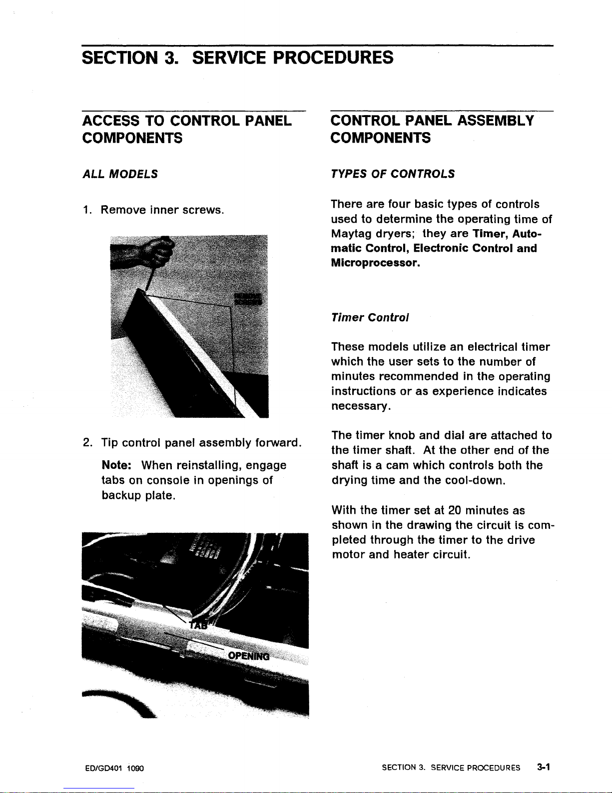
SECTION
3.
SERVICE PROCEDURES
ACCESS TO CONTROL PANEL
COMPONENTS
ALL
MODELS
1.
Remove
inner
screws.
2.
Tip
control
panel
assembly
forward.
Note: When
reinstalling,
engage
tabs on console in openings
of
backup plate.
ED/GD401 1090
CONTROL PANEL ASSEMBLY
COMPONENTS
TYPES OF CONTROLS
There
are
four
basic
typesofcontrols
used to
determine
the
operating
time
of
May
tag
dryers;
they
are
Timer,
Auto-
matic
Control, Electronic Control and
Microprocessor.
Timer
Control
These
models
utilize
an electrical
timer
which
the
user
setstothe
number
of
minutes
recommendedinthe
operating
instructionsoras
experience
indicates
necessary.
The
timer
knob and
dial
are
attached to
the
timer
shaft.
At
the
other
endofthe
shaft is a cam
which
controls
both the
drying
time
and
the
cool-down.
With the
timer
set at 20 minutes as
shown in the
drawing
the
circuit
is com-
pleted
through
the
timertothe
drive
motor
and
heater
circuit.
SECTION3.SERVICE PROCEDURES
3-1
Page 30
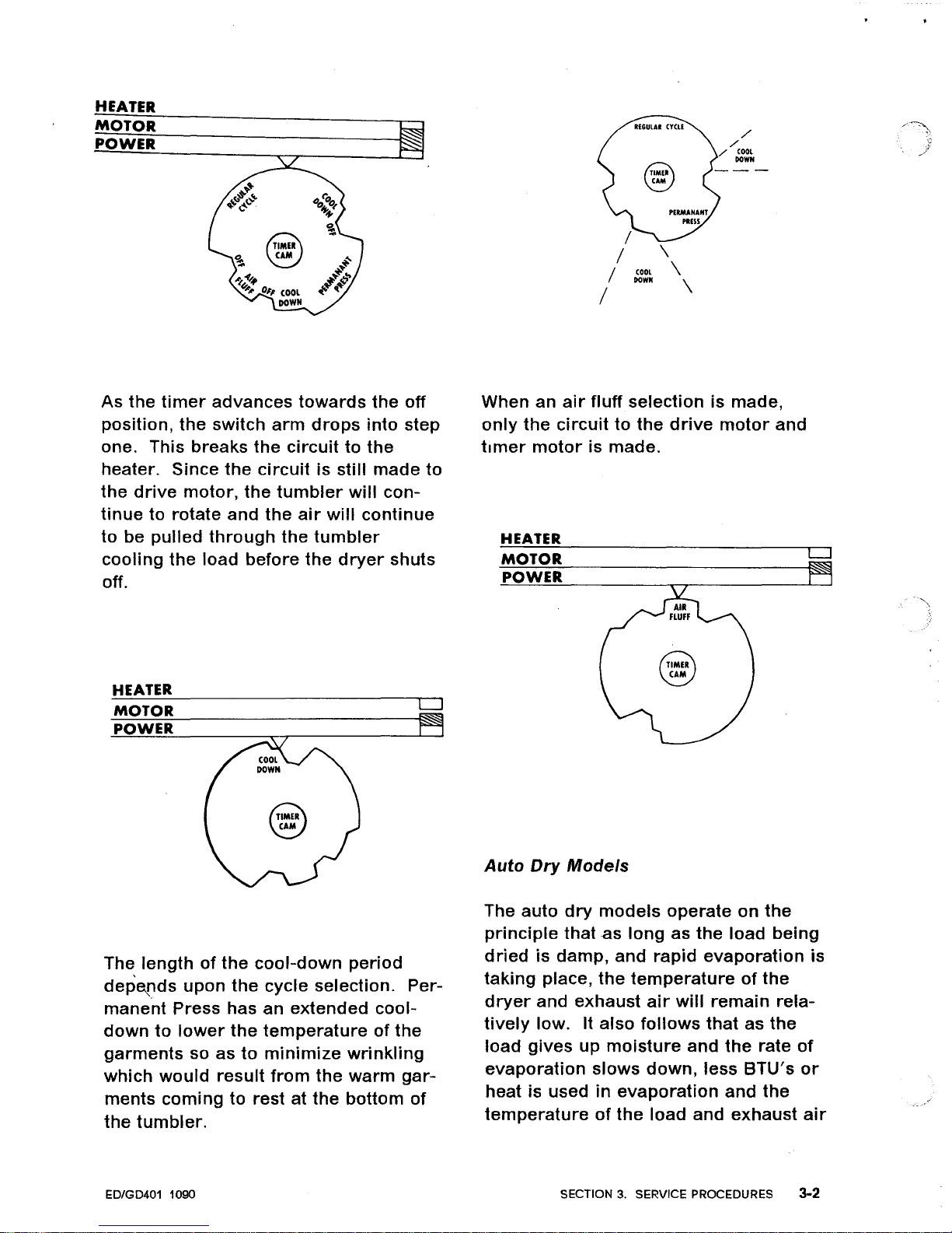
HEATER
MOTOR
POWER
~
~
/
./
./
coo,
GOWN
\
COOL
\
GOWN
\
As
the
timer
advances
towards
the
off
position,
the
switch
arm
drops
into
step
one. This breaks
the
circuittothe
heater. Since
the
circuitisstill
made
to
the
drive
motor,
the
tumbler
will
con-
tinue
to rotate
and
the
air
will
continue
to
be
pulled
through
the
tumbler
cooling
the
load
before
the
dryer
shuts
off.
HEATER
MOTOR
POWER
LJ
~
When an
air
fluff
selection is
made
,
only
the
circuittothe
drive
motor
and
timer
motor
is made.
HEATER
MOTOR
LJ
POWER
Auto
Dry
Models
The
lengthofthe
cool-down
period
depetlds
upon
the
cycle
selection. Per-
manent
Press has an
extended
cool-
downtolower
the
temperatureofthe
garments
so
astominimize
wrinkling
which
would
result
from
the
warm
gar-
ments
coming
to rest at
the
bottom
of
the
tumbler.
ED/GD401 1090
The auto
dry
models
operate
on
the
principle
that
as
long
as
the
load
being
driedisdamp,
and
rapid
evaporation
is
taking
place,
the
temperatureofthe
dryer
and
exhaust
air
will
remain
rela-
tively
low. It
also
follows
thatasthe
load
gives
up
moisture
and
the
rate
of
evaporation
slows
down,
less
BTU's
or
heat is usedinevaporation
and
the
temperatureofthe
load
and
exhaust
air
SECTION3.SERVICE PROCEDURES 3-2
Page 31

increases. With
thisinmind,
let's
look
at
the
circuitry.
With
the
timer
setinthis
position,
the
circuits
are
completedtothe
heat
source
and
drive
motor.
POWER
Note: The switch
controlling
the
timer
motor
is open.
TO HEAT
CYCLING
THERMOSTAT
MOTOR
TO TIMER
WITH CYCLING THERMOSTAT
CALLING
FOR
HEAT
(NORMAL)
At
the
beginningofthe
cycle
the
load is
damp,
the
heat
inputisused
up in
evaporationofthe
moisture
and
there
is
little
increaseinthe
air
temperature.
As
the
load becomes
drier,
less heat is
used up
in
evaporation
and
the
temper-
atureofthe
load and exhaust
air
starts
to
rise. The exhaust
airisbeing
pushed
over
the
regulating
thermostat
and
as
the
temperatureofthe
exhaust
air
rises so
does
thatofthe
thermostat.
Once
the
thermostat
reaches a
temper-
atureofapproximately
1400F
the
circuit
is
brokentothe
heat
source
andatthe
same
timeiscompletedtothe
timer
motor.
DRIVE
MOTOR
HEAT
SOURCE
TIMER
MOTOR
l'
TIMER
SET
HERE
When
the
timer
is settoa
degree
of
dryness,
the
circuitiscompletedtothe
heat source
and
the
drive
motor.
The
difference between
this
control
and a
,
standard
timer
operated
dryeristhe
fact
that
the
timer
motorisnot
initially
in
the
circuit.
To see
how
the
control
works,
let's
assume
that
the
loadtobe
dried
is a
normal
load with
the
gar-
mentsofsomewhat
uniform
weight,
the
auto
regular
setting is selected and
the
dial
set on the
middle
mark
between
"more
dry"
and
"less
dry".
As
indicatedinthe
timer
schematic
below,
the
maximum
timer
controlled
drying
time
on
an
auto-dry
regular
setting is
approximately
31
minutes
plusafive"minute
cool-down.
Since we
set the
dialtothe
middle
mark
we have
set
the
timeratabout
the
mid
point
or
for
approximately
15
minutesoftimed
dry.
ED/GD401 1090
SECTION3.SERVICE PROCEDURES 3-3
Page 32

POWER
CYCLING
THERMOSTAT
HAS
REACHED
TEMPERATURE
(OPEN)
At
this
point
the
unheated
airiscooling
the
load and
the
timer
motor
is
advancing
the
timer
towards
the
off
position.
In
this
example,
after
a totalofapproxi-
mately
13
minutesofheat off
time
the
timer
will
have
advanced
to
the
point
where
Cam 2 closes
the
timer
motor
switch whichinturn
advances
the
timer
outofthe
heat
portionofthe
cycle and
into
the
cool-down
period.
Each
time
the
thermostat
cycles
the
heat
periodisshorter
and
the
heat off
(timer
motor
on)
timeislonger.
will
take a
relatively
long
period
of
time.
By
the
same token,
the
moisture
content
and
the
evaporation
rate
taking
place
during
the
first
heat off
period
makesitshorter
than subsequent heat
off
periods.
CYCLING
THERMOSTAT
TO
HEAT
MOTOR
TO TIMER
As
the
temperatureofthe
tumbler,
the
items
being
dried
and
the
exhaust
air
decrease, so
does
the
temperature
of
the thermostat. When
the
thermostat
cools to a
temperatureofapproximately
1250F.
the
thermostat
returnstoits
normal
position
breaking
the
circuit
to
the
timer
motor
and
again
completing
the
circuittothe
heating
elementorgas
valve.
A selectionofthe
middle
mark
is a
good
starting
point. Experience
gained
from
drying
a few
loads
will
enable
the
operatortopickapoint,
either
more
or
less
dry,
which is
most
pleasing. Once
this
pointisdetermined,itcan be used
for
most
loads
as
the
automatic
control,
based
upon
time
and
temperature,
will
automatically
adjust
itselftothe
size
of
load.
Note: The
temperatures
quoted
are
the
operating
temperaturesofthe
thermo-
stat and
not
the
temperature
of
the
clothingorexhaust
air.
Becauseofits
mass,
the
thermostat
will
heat up and
cool
down
slower
than
the
air
temper-
ature.
Because
of
the
moisture
content and
the
evaporation
rate,
the
first
temper-
atur'e
rise
and
cyclingofthe
thermostat
\.
If
the
operatorisdryingapoorly
mixed
load;
bulky
items
such as cotton socks
along
with
lightweight
flat
items
it
would
be
desirable
to
move
the
dial
to
the
"more
dry"
so
that
more
time
is
availabletocondition
the
loadorto
allow
the
moisturetosurface on
the
bUlky items. This is
not
necessary
on
a
more
uniform
loadofeither
bulky
or
lightweight
items.
ED/GD401 1090 SECTION
3.
SERVICE PROCEDURES 3-4
Page 33

TIMER
A
timer
is a
motor
driven
package
of
switches that establishes a sequence
of
operation.
To
Replace Timer:
1~\Pry
out
cap.
2. Remove
nut
and
dial.
3. See Access To
Control
Panel
Com-
ponents.
4.
Remove
timer
screws.
ED/GD401 1090
TIMER
MOTOR
1.
See Access To
Control
Panel Com-
ponents.
2. Remove
two
screws
securing
motor
to
timer.
Note: It
may
be necessarytoremove
timer.
SECTION 3. SERVICE PROCEDURES
3·5
Page 34

TEMPERATURE
SWITCH
A switch that
allows
selectionoftem-
peratures.
1.
See Access To
Control
Panel
Com-
ponents.
2. Remove switch
from
back-up plate
by
removing
two
screws
holding
switch to back-up plate.
CONTROL
PANEL
1.
Remove
timer
dial.
2. See Access To
Control
Panel
Com-
ponents.
3. Remove end caps.
4.
Insert
a flat
bladed
screwdriver
between
the
top
portionofthe
control
panel
and
back-up plate
and
gently
pry
the
two
apart.
5.
Disengage notchesofcontrol
panel
from
slots in
bottomofback-up
plate.
ED/GD401 1090
SECTION
3.
SERVICE PROCEDURES
3-6
Page 35

BUZZER
Many
model
dryers
incorporate
a
buzzer
which
signals
the
endofthe
cycle on all
dry
selections. The
buzzer
is
wiredinparallel
with
the
timer
con-
tacts
for
the
drive
motor.
1.
See Access To
Control
Panel
Com-
ponents.
2. Remove
buzzer
by
removing
one
screw
securing
mounting
bracket
to
back-up plate.
3. On
some
models
note the shaft
of
buzzer
and
corresponding
slot
in
pivot
armofslide
lever.
ADJUSTABLE
BUZZER -
ADJUSTABLE
SLIDE LEVER
The
lever
on
the
endofcycle signal can
be
adjusted
by
the
customer.
The
signal
control
lever
is raised
to
increase and
loweredtoreduce
or
eliminate
the
buzzer
tone.
1.
Remove buzzer. One
screw
secures
buzzertomounting
bracket.
2. Remove
slide
lever
with
pivot
arm.
Note
positionofpivot
arm,
slide
lever
and
retaining
plate
for
future
mounting
procedures.
Two screws
secure
mounting
plate
for
lever.
PUSH-TO-START SWITCH
1.
See Access To
Control
Panel
Com-
ponents.
,2.
Remove
two
screws
holding
switch
\ and
brackettoback-up plate.
ED/GD401 1090
AUTO-DRY
SWITCH
1.
See Access To
Control
Panel Com-
ponents.
2. Remove switch
by
taking
out
two
screws
holding
switch to back-up
plate.
PRESS CARE SWITCH
1.
See Access To
Control
Panel Com-
ponents.
2. Remove switch.
SECTION3.SERVICE PROCEDURES 3-1
Page 36

ED/GD401
1090
SECTION3.SERVICE PROCEDURES 3·8
Page 37

ELECTRONIC CONTROL MODELS
Asinthe
other
control
systems,
the
sole
purposeofthe
electronic
control
is
to
shut
the
dryer
offatthe
endofthe
drying
cycle. The
electronic
control
system
reactstomoistureinthe
clothes
to
keep
the
dryer
running
until
the
clothes
are
dry.
For
testing
and
electrical
operation,
see
Section
2.
CONTROL PANEL REMOVED
Electronic
Control
Models
The
electronic
control
assembly,incon-
junction
with
the
sensor
assembly,
is
used
for
determining
when
the
clothes
have
reached
the
selected
dryness
level.
This
assembly
consistsofthree
components:
edgeboard
connector
assembly,
relay
and
electronic
control
board
(printed
circuit
board). These
components
are
locatedinthe
left
hand
cornerofthe
control
console.
ED/GD401 1090
To
remove
the
electronic
control
assembly
components:
1.
Disconnect
the
power
supply.
2.
Remove
the
two
inside
screws
on
control
panel
and
tilt
panel
forward.
3. To
remove
the
electronic
control
board
(printed
circuit
board).
A.
Grasp
the
board
on
both
sides
with
thumb
and
fingers.
B. Pull
straight
back
while
twisting
the
board
back
and
forthina
side-
ways
motion.
Note
which
sideofthe
boardisfacing
up.
4. To
remove
relay:
A.
Disconnect
the
wires
going
to
the
relay.
B.
Remove
the
two
screws
securing
the
relaytothe
bracket.
5. To
remove
the
edgeboard
connector
assembly:
A.
Remove
the
two
screws
securing
the
assemblytothe
back-up
plate.
B.
Disconnect
the
remaining
wires
to
remove
assembly.
DRYNESS SWITCH
1.
Gain
accesstocontrol
panel.
2.
Remove
switch.
SECTION3.SERVICE PROCEDURES 3-9
Page 38

MICROPROCESSOR BOARD CONTROL
The
microprocessor
board
receives
input
information
from
the
various
components
involved
with
the
operationofthe
dryer;
such as
the
dryness
sensor
and
the
thermistor.
It uses
this
information
to
determine
the
necessary
control
for
the
com-
pletionofthe
cycle.
CONTROL PANEL REMOVED -
Microprocessor
Models
To
remove
microprocessor
board:
1.
Disconnect
power
supply.
2. Remove
the
two
inside
screws on
control
panel and
tilt
panel
forward.
3. Disconnect
the
three
edgeboard
connectors
from
the
microprocessor
board.
4.
Remove
the
eight
nuts
securing
the
microprocessor
boardtothe
mounting
panel.
To
remove
mounting
panel
assembly:
Remove
the
four
nuts
securing
the
mounting
panel to
the
back-up plate.
ED/GD401 1090
SECTION 3. SERVICE PROCEDURES
3-10
Page 39

ED/GD401 1090
SECTION 3. SERVICE PROCEDURES
3-11
Page 40

To
remove
transformer:
1.
Disconnect
power
supply_
2. Remove
the
two
inside
screws on
control
panel
and
tilt
panel
forward.
3. Disconnect
the
wires
goingtothe
transformer.
4.
Remove
the
two
screws
securing
the
transformertothe
dryer
top
cover.
To
remove
motor
relay:
1.
Disconnect
power
supply.
2. Remove
the
two
inside
screws on
the
control
panel and
tilt
panel
forward.
3. Disconnect
the
wires
goingtothe
relay.
4.
Remove
the
two
screws
securing
the
relaytothe
dryer
top
cover.
To
remove
heater
relay
(Electronic
Dryer
Only):
1.
Disconnect
power
supply.
2.
Remove
the
two
inside
screws on
control
panel and
tilt
panel
forward.
3. Disconnect
the
wires
goingtothe
relay.
4.
Remove
the
two
screws
securing
the
relaytothe
dryer
top
cover.
\.
ED/GD401 1090
SECTION 3. SERVICE PROCEDURES
3-12
Page 41

FRONT
PANEL
AND
COMPONENTS
\
DOOR HINGES
~~
~~
~,
FRONT
PANEL
~
~
SCREWS
INNER
DOOR
GAS
VALVE
ACCESS DOOR
GAS
MODELS
ONLY
OUTER
DOOR
ED/GD401 1090
SECTION 3. SERVICE PROCEDURES 3-13
Page 42

FRONT PANEL REMOVAL
1.
Remove screws.
2.
Lift up on
front
panel and
swing
bottomofpanel away
from
dryer
to
disengage
topofpanel
from
dryer
top.
J
UFl'UP
SWING
OUT
3.
Front
panel
may
be set offtoone
side
orifnecessary,
the
door
switch
EO/GD401 1090
wires
may be
disconnected
and
the
front
panel
removed
completely
from
the
unit.
DOOR SEAL
1.
Open
door.
2. Grasp one end
and
pull
gasket
from
door.
3.
When
installing
the
door
gasket,
the
thicker
end fits
behind
the
tabs
on
the
door.
4. Install one endofthe
gasketatthe
bottomofthe
door
and
work
the
gasket
behind
each tab.
Note: It
may
be
necessarytocut
1/2"
from
one endofthe
replacement
gasket.
DOOR REMOVAL
1.
Open
door.
2.
Support
door
and
remove
four
screws (two
from
upper
hinge
and
two
from
lower
hinge)
which
hold
the
door.
SECTION 3. SERVICE PROCEDURES 3-14
Page 43

3. Remove
door.
TO DISASSEMBLE DOOR
1.
Remove
door
hinge
screws
from
door.
2. Remove
two
screws on
edgeofdoor
opposite
hinges
and
two
screws
from
bottomofdoor.
3. Remove
screw
holding
door
handle
and separate
door
halves.
FLUSH MOUNTED HANDLE
1.
Remove
cross
head
screw
from
upper
inside
door
panel
securing
handletodoor.
2. Pull
handle
out.
ED/GD401 1090
DOOR STRIKE
1.
Remove
cross
head
screw
on
right
edge of
door
panel.
2. Disengage
clip
and
strike
from
panel.
DOOR HINGES
1.
Remove
door
from
dryer.
2. Remove
front
panel because each
door
hhlge
is backed
up
by
a
retaining
clip
which
will
fall
from
place when
the
hinge
is removed.
3. Remove
two
screws
holding
each
hingetothe
front
panel.
4.
Remove
two
screws
holding
hinges
to
door
panel.
DOOR SWITCH
1.
Remove
front
panel.
2. Squeeze
the
expanded
endofthe
latch
together
and
remove
latch.
FRONT PANEL SEAL
To
maintain
the
proper
air
flow
pattern
and
therefore
the
desired
drying
results,
the
seal
which
fits
around
the
door
openinginthe
inner
front
panel
must
beinplace
andingood
shape.
1.
Remove
front
panel.
2. Remove
old
seal.
3. Install
replacement
seal
by
rolling
seal
over
the
front
panel
lip.
SECTION 3. SERVICE PROCEDURES 3-15
Page 44

\.
FRONT PANEL
ED/GD401 1090
SECTION
3.
SERVICE PROCEDURES 3·16
Page 45

TUMBLER AND RELATED COMPONENTS
TUMBLER
REAR
OUTLET
~
FRONT
BEARING
~~~
/
~
AND PAD
SENSOR
INTERIOR
LIGHT
(120V - 7 Watt)
The
drum
lightisat
the
upper
center
of
the
tumbler
opening.
It is
wired
in
series
with
the
door
switch so that
the
light
comes on,
illuminating
the
drum,
only
when
the
door
is open.
L~GHT
REPLACEMENT
1.
Open
door.
2.
Unscrew
bulb.
ED/GD401 1090
LIGHT
RECEPTACLE
1.
Remove screws
from
Front
Panel
and
swing
panel aside.
2. Remove
wires.
3. Remove
nut
from
left
hand
mounting
tab.
4.
Pull
up
on receptacletodisengage
from
tumbler
front.
SECTION 3. SERVICE PROCEDURES 3-17
Page 46

DRYNESS SENSOR
To
remove
the
dryness
sensor:
1.
Disconnect
power
supply.
2. Remove the
front
panel.
3. Remove
the
wires
goingtothe
dryness
sensor,
W-BK
and W-BK.
4.
Remove
the
two
screws
securing
the
dryness
sensortothe
bulkhead.
To check
the
dryness
sensor:
CAUTION
-----------,
Always
disconnect
power
supply
before
making
continuity
or
resist-
ance checks.
1.
Disconnect
power
supply.
2. Remove both
wires
goingtothe
sensor
bars.
3. Check
for
continuity
across
the
sensors. Attach
meter
across
the
terminal
on each sensor. If
you
have
continuity,
replace
dryness
sensor.
4. Check
for
circuittoground
from
either
sensor
bar. Replace both
wire
connectors
on
the
spade
termi-
nals. Place
one
meter
lead on
the
sensor
bar
inside
the
drum
and
place
the
other
meter
lead on
cabinet
ground.Ifyou
have conti-
nuity, check
to
make
sure
the
wire
connectors
are
not
making
contact
with
the
front
bulkhead. The
insu-
lated
wire
connector
goes on
the
terminal
closesttothe
bulkhead.
ED/GD401 1090
TUMBLER FRONT
The
tumbler
front
holds
the
frontofthe
tumbler
in the
correct
position
and
pro-
vides
the
bearing
surfaces
for
the
tumblertoride
on.
1.
Remove
front
panel.
2. Remove
four
screws
holding
tumbler
front
to cabinet.
3. Remove
screw
holding
ground
wire
to cabinet.
4.
Disconnect
wires
from
retainer.
5.
Pull
tumbler
front
out
and
away
from
tumbler.
Note: Two tabs on each
sideofthe
tumbler
front
fit
into
notchesinthe
front
of
the
cabinet. These
must
be
disen-
gagedtoremove
tumbler
front.
LINT
FILTER SWITCH
The
lint
filter
switch
producesa"Check
Filter"
warninginthe
dryer's
display
if
the
lint
filter
is not
removed
and
replaced
after
the
dryer
goes into
cool-
downatthe
endofa cycleorat
the
end
of
Air
Fluff. Leaving
the
filter
out
will
also activate
the
warning.
The switch is
a reed switch
mounted
on
the
outlet
duct
assembly
and connectedtothe
microprocessor
board
through
edgeboard
connector
CC
(refertosche-
matic). Its contacts
are
closed
by
a
magnet
that
is stakedtoone
sideofthe
lint
filter. The contacts close
when
the
lint
filterisinserted
into
placeinthe
outlet
duct
assembly. When
the
lint
filterisremoved
the
contacts
will
open.
Note: The switch
does
not
prevent
the
dryer
from
operating,
its
functionisto
produceawarningtomake
operator
SECTION3.SERVICE PROCEDURES 3-18
Page 47

awareofthe
necessity
for
cleaning
the
lint
filter.
To
remove
lint
filter
switch:
1.
Disconnect
power
supply.
2.
Remove
the
front
panel.
3. Separate
the
plastic
wire
connector
by
pUlling
apart.
4. Remove
the
two
screws
that
secure
the
switchtothe
outlet
duct
assembly.
To
check
the
lint
filter
switch:
CAUTION
----------,
Always
disconnect
power
supply
before
making
continuity
or
resist-
ance
checks.
1.
Separate
plastic
connector
by
pUlling apart.
2.
Check
for
continuity.
Attach
meter
across
wire
BR
and
BR
on
switch
sideofplastic
connector.
Remove
and
replace
lint
filter
to
check
for
opening
and
closingofthe
switch's
contacts.
COMPLETE OUTLET
DUCT
The
outer
halfofthe
outlet
ductisheld
to
the
frontofthe
tumbler
front.
1> Remove
front
panel.
2.
Remove
four
hex
screws
and
one
pozi-drive
screw
holding
outer
outlet
ducttotumbler
front.
3.
Remove
front
bulkhead.
ED/GD401 1090
4. Remove
outlet
duct.
TUMBLER FRONT BEARING
AND
PADS
At
the
bottom
insideofthe
tumbler
front
are
two
poly
teflon
bearings
which
rest on
cork
pads. These
bearings
provide
a surface
for
the
frontofthe
tumbler
to
ride
on.Ifitisnecessary
to
replaceafront
bearing,
remove
the
tumbler
front,
drill
out
old
rivets
and
rivet
new
bearings
on. In
positioning
the
bearing
and
pad,
the
projections
on
both
should
face
the
tumbler.
This
allows
the
bearingtostick
out
beyond
the
metalofthe
tumbler
front.
·Bearing
Note:
Two
tabs
on
each
sideofthe
tumbler
front
fit
into
notchesinthe
front
of
the
cabinet. These
must
be
disen-
gaged
to
remove
tumbler.
TUMBLER FRONT SEAL
The seal fits
around
the
back
circumfer-
enceofthe
tumbler
front.Itisanatural
felt seal
whichisdoubled
over
for
self-
adjusting
tension.
The
surface
which
comesincontact
with
the
revolving
tumbler,iscoated
withalayerofTeflon
to
provideaslick
durable
wear
surface.
The seal
is
heldinposition
by
formed
locking
tabs.
1.
Remove
tumbler
front.
SECTION 3. SERVICE PROCEDURES 3-19
Page 48

2. Remove
the
old
seal
by
prying
the
locking
tabs out
witharegular
screwdriver.
The Teflon coated
side
(which is
the
lighterofthe
two
colors)
goes
against
the
tumbler.
The seal is then
looped
in
a
"U"
shape so
the
slot
edge of
the
lighter
colored
sideisto
the
tumbler
front.
Rubber
adhesive
is used to
hold
the seal
overlap.
Bend tabs back
over
seal with a
pair
of
pliers.
TUMBLER ALSO RIDES AGAINST
LIGHT COLORED SIDE
TUMBLER
AND
BELT
The
tumbler
is a
round
cylinder
with
no
permanently
attached
front
or
back.
Tumbler
speed is
47
RPM. It
is
designed
so
there
is no
front
or
back.
Installation can be
made
without
regard
to
which
wayitcame
outofa
dryer.
To
Remove
Tumbler
and
Drive
Belt:
1.
Remove
front
panel.
2. Remove
tumbler
front.
3.
Reach
under
tumbler
and
remove
drive
belt
from
motor
and
idler
pulleys.
THIS
SID~AGAINST
TUMBLER
BACK
I
4.
Slip
belt
off
tumbler.
5. Pull
tumbler
outofcabinet.
ED/GD401 1090
SECTION
3.
SERVICE PROCEDURES 3-20
Page 49

INSTALLING DRIVE BELT
1.
Install
tumbler.
2.
Place belt
over
the
topofthe
dryer
tumbler
with
the
smooth
side
against
the
tumbler
and position it
about 1
1/2"
in
frontofthe
back
screws which
hold
the
clothes
lifters. In
ordertoget
the
belt
between
the
bottomofthe
tumbler
and
the
blower,itwill
be necessary
to lift up on
the
tumbler.
3.
The best
positiontotake
while
installing
the
belt is to sit on
the
floor
facing and as closetothe
dryer
as possible. Place
your
left
arm
along
the
left
sideofthe
tumbler
and
your
right
arm
along
the
bottomofthe
tumbler
(as close
to
the
blower
as possible).
4\
With
the
right
hand,
loop
the
belt
over
the
topofthe
motor
pulley
making
certain
the
groovesofthe
belt
are
against
the
pulley
and
that
the
beltisproperly
seated into
the
pulley.
ED/GD401 1090
5. With
the
left
hand,
loop
the
belt
under
the
motor
pulley.
6. With
the
right
hand,
position
the
belt
over
the topofthe
idler
pulley
and
begintoworkitaround
the
circum-
ference of
the
idler
pulley
while
pushing
the
pulley
up
andtothe
left.
Note: It is
neither
necessary
nor
advantageous
to push
extremely
hard
on
the
pulley. This
tends
to
put
the
idler
pUlley and
motor
pUlley
in a
bind
and also puts a
strain
on
the
installer
so he cannot
work
effi-
ciently
with
his
handstocomplete
the
belt
installation.
7. Once
tl'1e
belt is
almost
around
the
entire
circumferenceofthe
idler
pulley, use
the
left handtopush
the
belt
over"the
bottomofthe
idler
pulley
whileatthe
same
time
making
certain
that
the
belt
is
between
the
idler
pulley
and
the
belt
gUide.
SECTION3.SERVICE PROCEDURES 3-21
Page 50

8.
With
the
belt
completely
installed,
feel with both
hands
to see that it is
properly
positionedinthe
motor
pulley
andinthe
approximate
middleofthe
idler
pulley.
When
you
have
determined
by
feeling that
it
is installed
correctly,
lift up and
push back
while
slowly
turning
the
tumbler
oneortwo
revolutionsina
clockwise
directiontoallow
the
belt
to
properly
align
itself.
CLOTHES LIFTER
There
are
three
tumbler
clothes lifters
used to
aidintumbling
the
clothes.
Two
of
the
lifters
are1"higher
than
the
other. Location makes no difference.
1.
Remove
front
panel.
2.
R~move
two
screws
holding
each
liftertothe
tumbler.
ED/GD401 1090
For
ease in
replacing
a clothes
lifter
you
will
find a
locating
tab
on
the
undersideofthe
lifter. Pilot holes
are
also
foundinthe
tumbler.
When
the
clothes
lifter
is installed,
the
tab
is
inserted
into the slotinthe
tumbler.
This
correctly
aligns
the
screw
holes
in
the
lifter
with
thoseinthe
tumbler.
ROLLER
AND
BEARING
ASSEMBL
Y
The
tumbler
roller
consistsofa
rubber
tire
bonded
to a plastic hub.
There
are
two
roller
and
bearing
assemblies attachedtothe
tumbler
rear.
Normally
the
rollers
will
run
slightly
behind
the
drum
radius. If
the
rollers
are
riding
up on
the
tumbler
radius,
check
for
bent
rear
roller
brackets. If a bracket is bent, replace
tumbler
rear.
1.
Remove
front
panel.
2. Remove
tumbler
front.
3. Remove
tumbler.
4.
Remove
retaining
ring
from
groove
in
shaft.
5. Remove
fiber
washer.
6. Remove
roller.
7. To
remove
roller
shaft
remove
nut
on back.
Note: There is a
spacer
washer
behind
the
roller.
When
replacing
parts be
certain
the
orderofthe
replacement
is
correct.
SECTION3.SERVICE PROCEDURES 3·22
Page 51

00
Lubricate
with MAYTAG 55975 S.B.L.
TUMBLER
REAR FELT SEAL
The seal fits
around
the
front
circumfer-
enceofthe
tumbler
rear. It is a natural
felt seal which is
doubled
over
for
self-
adjusting
tension. The surface which
comes
in
contact
with
revolving
tumbler
is coated
withalayer
of Teflon to
provideaslick
durable
wear
surface.
1.
The felt seal
for
the
rear
tumbler
can
be replaced
from
the
frontofthe
dryer.
However,
for
easeinser-
vicing,
we
recommend
removal
of
the
tumbler
rear
from
the
dryer.
2. Remove
the
old
seal by
prying
the
locking
tabs
out
witharegular
screw
driver.
3. The Teflon coated
side
(which is
the
lightofthe
two colors) goes
against
the
tumbler.
The seal is then
looped
in a
"U"
shape so
the
slot edge
of
the
light
colored
side
is cemented
to
the
tumbler
back.
Rubber
adhesive
is usedtohold
the
seal
overlap.
4.
Install new seal and bend tabs
back
over
seal
withapairofpliers.
\.
ED/GD401 1090
TUMBLER
ALSO
RIDES AGAINST
LIGHT COLORED SIDE
I
THIS SIDE AGAINST
TUMBLER
BACK
TUMBLER
REAR
The
tumbler
rear
is securedtothe
back
panel by
four
screws. It is finished with
an epoxy
powder
coat
which
is a
very
smooth surface, resistanttoscratches
and
abrasion.
The
tumbler
rear
acts as a
support
for
two
roller
assemblies
which
support
the
tumbler
and
weightofthe
load.
Removal:
1.
Remove
front
panel.
2. Remove
tumbler
front.
3. Remove
tumbler
and belt.
4.
Remove heat cone.
5.
From
backofdryer,
remove
four
screws
holding
tumbler
back
assembly
and
remove
assembly.
SECTION3.SERVICE PROCEDURES 3-23
Page 52

THERMOSTATS
THERMOSTATS
There
are
three
different
kindsofther-
mostatsinthese
dryers.
1.
Bi-Metal
type~
2. Resistance
type
(Multi-temperature).
3. Thermal Fuse type.
All
react
essentiallytotemperature
with
direct
effect on heat onorheat off func-
tionsofa
dryer.
To
remove
those
located
on
blower
cover:
1.
Remove 2 screws
from
Front
Panel
and swing panel out.
2. Remove
wires
from
thermostat.
3. Remove screws
securing
thermostat
to cover.
160
0
THERMOSTAT -
Microprocessor
Models
Bi-Metal
Type
The 160°
thermostat
functions as a back
up
to
the
thermistor.
It is
mounted
on
the
blower
cover. The
thermistor,
in
conjunction
with
the
microprocessor
boar~
and
heater
relay, is used
to
control
the
cyclingofthe
temperature
between 135°F and 155°F. The 160°
thermostat
is placed in series
with
the
gas
valve
I heating element and
will
open
the
heat
circuitinthe
event
the
thermistor
failstoopen
the
circuit
at
temperatures
above
155°F.
ED/GD401 1090
To
remove
the
1600thermostat:
1.
Disconnect
power
supply.
2.
Remove
front
panel.
3. Remove
the
thermostat
cover
mountedtothe
base (electric
dryer
only).
4.
Disconnect
wires
from
the
thermo-
stat.
5.
Remove
the
two
screws securing
the
thermostattothe
blower
cover.
To check
the
1600thermostat:
CAUTION
----------,
Always
disconnect
power
supply
before
making
continuity
or
resist-
ance checks.
Check
for
continuity
across
thermostat
at
room
temperature.
Attach
meter
across
terminals
BK
and PU. No conti-
nuity, replace.
THERMISTOR
-
Microprocessor
Models
Resistance Type
The
thermistor
is a
semiconductor
device
(solid state)
that
has a negative
temperature
coefficientofresistance;
its resistance
decreases
as its
temper-
ature
increases and
vice
versa. The
thermistor
functions
as
the
"sensing
control"
for
the
dryer's
heat
circuit.
No..
cycling
thermostat
is used. It is
mounted
on
the
blower
cover
and is
SECTION3.SERVICE PROCEDURES 3-24
Page 53

connectedtothe
microprocessor
board
through
edgeboard
connector
CC
(refer
to schematic).
Mounted
on
the
blower
cover
puts
the
thermistor
in
the
air
flow
of
the
air
being
exhausted
from
the
drum.
The
increasing
or
decreasing
temperatureofthe
exhausted
air
changes
the
resistanceofthe
thermistor.
The
microprocessor
board
uses
this
input
information
to
control
the
heat
circuit.
On
the
electric
dryer
the
microprocessor
board
controls
the
24
DC
voltagetothe
heater
relay, on
the
gas
dryeritcontrols
the
L1
side
of
the
power
supply
through
edgeboard
connector
BB
(refertoschematic).
To
remove
thermistor:
1.
Disconnect
power
supply.
2. Remove
front
panel.
3" Remove
the
thermostat
cover
mountedtothe
base (electric
dryer
only).
4.
Remove
the
two
wires,
PK-BK
and
PK-BK,
from
the
thermistor.
5.
Remove
the
two
screws
that
attach
the
thermistortothe
blower
cover.
ED/GD401 1090
Check
the
thermistor:
1.
Remove
the
two
wires
on
the
thermistor,
PK-BK
and PK-BK.
2. Place
ohm
meter
across
these
wires
and check resistanceofthe
thermistor.
At
room
temperature,
77°F, you
should
read
about
10,000
ohms.
At
140°F
you
should
read
about
1750 ohms.
Note: Do not check
with
line
voltage
(120 VAC),
the
thermistorispartofthe
low
voltage
circuitry.
THERMAL FUSES
The functionofthe
thermal
fuse and
thermal
cut-off istostop
the
dryer
in
the
event an
over
heating
condition
should
occur. The
electric
dryer
has a
thermal
fuse
mounted
on
the
right
side
of
the
heat cone and a
thermal
cut-off
mounted
on
the
blower
cover. The gas
dryer
has a
thermal
cut-off mounted on
the
blower
cover.
Both
are
referred
to
as
"thermal
fuse"
on
the
electrical
schematic. The
thermal
fuse
and
cut-off
are
placed in
series
with
the
drive
motor.
If oneofthese
should
open, the
drive
motor
will
stop and
the
circuit
through
the
centrifugal switch
for
the
gas
valve
/ heating
element
will
also
open,
breaking
the
heat
circuit.
The
thermal
fuse and
thermal
cut-off
are
not
interchangeableorresettable and
must
be replaced
after
the
over
heating
problemiscorrected.
Note:
If
oneofthese
thermal
devices
opens,itindicates
something
has
caused an
unusual
amountofheat
to
build
up
around
the
device.Ifthis
happens,
depending
on
the
model,
REPLACE
the
hi-limit
thermostat
and
cycling
thermostat
or
the
hi-limit
ther-
SECTION 3. SERVICE PROCEDURES 3-25
Page 54

mostat and
the
160°
thermostat
and
thermistor/microprocessor
board
com-
bination
along
with
the
thermal
device
that failed.
To
remove
thermal
fuseorcut-off:
1. Disconnect
power
supply.
2. Remove
front
panel.
3.
Remove
thermostat
cover
mounted
to
the
base (electric
dryer
only).
4. Disconnect
the
wires
from
the
thermal
cut-off.
5. Remove
the
two
screws attaching
the
thermal
cut-off to
the
blower
cover.
6.
For
the
fuse
mounted
on
the
heat
cone (electric
dryer
only).
A. Remove
the
screw
that secures
the
fuse brackettothe
heat cone.
B. Remove
wires
and
the
two
screws
that
attach
the
fusetothe
bracket.
To
check
the
thermal
fuseorthermal
cut-off:
CAUTION
---------.,
Always
disconnect
power
supply
before
making
continuity
or
resist-
ance checks.
1.
Disconnect
power
supply.
ED/GD401 1090
2. Remove
front
panel.·
3.
Remove
wires
from
the
thermal
fuse
or
thermal
cut-off.
4. Check
for
continuity.
Attach
meter
across
the
terminalsofthe
fuse
or
cut-off. No
continuity,
replace fuse.
MUL
T1-
TEMPERA
TURE
Resistance Type
These
thermostats
have 3
temperature
options
depending
on
resistorsinthe
circuit.
For
example, no
resistor
(internallyinthermostat
oratselector
switch);
cycling
temperature
will
be
150°, Full
voltage
(through
internal
resistor
in thermostat); cycling
temper-
ature
will
be 140°.
If a series
circuit
is selected
using
resistorinthermostat
and
resistor
at
selector
switch,
cycling
temperature
will
be 145°.
To
replace
thermostat:
1.
Disconnect
power
supply.
2. Remove
front
panel.
3.
Remove
thermostat
cover
mounted
to
the
base
(electric
dryer
only).
4.
Disconnect wires.
5. Remove
two
screws attaching
thermosat
to
blower
cover.
SECTION3.SERVICE PROCEDURES 3-26
Page 55

BLOWER
RETAINING
RING
COVER FOR
BLOWER
SEAL FOR BLOWER
The felt seal
for
the
blower
is secured
to
the
lipofthe
cover
for
the
blower. If
a seal
is
replaced, clean surface
and
use Maytag Part No. 55978
rubber
adhesivetohold
seal.
COVER FOR BLOWER
1.
Remove
front
panel.
2. Remove
tumbler
front.
3. Remove
six
screws
holding
cover
to
blower
housing.
4. Remove
screw
holding
cover
to
\ base.
5.
It is
not
necessary to
remove
wires
from
thermostatstogain access
to
blower.
Simply
lay
blower
cover
forward.
ED/GD401 1090
BLOWER
HOUSING
BLOWER IMPELLER
The
blower
impeller
is attached
directly
to the
motor
shaft
and
behind
the
blower
cover.
1.
Remove
blower
cover.
2. Remove
clip
retaining
ring.
3.
Compress
and
remove
clamp
around
hubofimpeller.
4.
Work
impeller
back and forth
while
pulling
off shaft.
BLOWER HOUSING
1.
Remove
blower
impeller.
2.
Remove
clip
retaining
ring
located
behind
blower
impeller.
3.
Remove
four
screws
holding
blower
housing to
motor
mounting
bracket.
SECTION 3. SERVICE PROCEDURES 3-27
Page 56

4.
Remove
blower
housing.
5.
When
replacing
blower
housing
be
certain
the
clip
retaining
ring
is
properly
replaced into
the
groove
in
the
motor
shaft.
EXHAUST
DUCT
PIPE
One endofthe
exhaust
duct
pipe
is
heldtothe
back of
the
cabinet
by
one
screw. It fits
over
the
blower
housing
on
the
opposite
end.
the
heat
source
when
motor
reaches
speed.
The external
motor
switch is secured
to
the
motor
with
two
screws.
1.
Remove
front
panel.
2. Remove
tumbler
front.
3. Remove
tumbler.
4.
Remove
two
screws
holding
switch
to
drive
motor.
MOTOR
PULLEY
DRIVE MOTOR AND IDLER
ASSEMBLY
Shown is
the
2-groove, 60 Hz,
47
rpm
pulley. This
identifies
the
pulley
for
60
Hz. operation. 50 Hz. has 3
grooves.
A
switching
deviceina
motor
used
to
change
the
pathofelectricity
from
both
start and run
windings
to
run
winding
only. It also completes
the
circuit
to
1.
Remove
front
panel.
2. Remove
tumbler
front.
3. Remove
tumbler.
4.
Place hexhead
wrench
in set screw.
5.
Usingahammer
or
rubber
mallet,
stri ke
the
endofthe
hexhead
wrench, as shown.
NOTE
GROOVES
IDLER
PULLEY
MOTOR
PULLEY &
SET
SCREW
SPACER
IDLER ARM
& SHAFT
I
MOTOR
BASE
MOTOR
CLIPS
<~
MOTOR -J -
~
/
~
SWITCH
/~
.
'.
DRIVE
MOTOR
MOTOR
SWITCH
GROUND
WIRE
~---_I
ED/GD401 1090 SECTION3.SERVICE PROCEDURES 3·28
Page 57

MOTOR
SUPPORT
MOTOR
PULLEY
ADJUSTMENT
Positioningofthe pUlley on
the
motor
shaft is
important
for
proper
alignment
with
the
idler
assembly. The distance
from
the backofthe
motor
pulley
to the
face
of
the
motor
support
must
be 3/8".
A metal gage (Maytag Part No. 38623)
is
available
which can be used to
prop-
erly
position
the
pulley.
To
use
the
gage,
simply
place
the
thicker
part
against
the
motor
support
and
the
thinner
end between
the
pulley
and
the
mounting
ring.
With
the
proper
3/8"
dimension
established,
tighten
the
pulley
set screw.
ED/GD401 1090
When replacing
the
motor
pulley
make
sure
the
set
screw
aligns
with
the
flat
side
of
the
motor
shaft. Tighten set
screw securely.
DRIVE
MOTOR
AND
BASE
1.
Remove
front
panel.
2.
Remove
tumbler
front.
3.
Remove
tumbler.
4. Remove two screws securing
motor
base to base frame.
5.
Remove
wires
from
motor
and
unhook
idler
spring.
6.
Slide
motor
base tab
from
base
frame.
7. Remove
motor
and
blower
assembly
from
cabinet.
8.
Remove
blower
component
from
motor
..
Note: When
installing
motor,
be
sure to
slide
motor
base
tab
into
slotinbase frame.
SECTION 3. SERVICE PROCEDURES 3-29
Page 58

9.
Using
pliers
or
screwdriver,
roll
the
clips
offofthe
motor
mounts.
10.
Remove
motor
from
motor
base.
IDLER
ASSEMBL
Y
1.
Remove
front
panel.
2.
Remove
tumbler
front.
3.
Remove
tumbler.
4.
Remove
spring
and
screw
holding
assembly.
Note: When
replacing
the
idler
assembly
applyalight
coatingof56016
May
tag
center
seal
greasetothe
motor
support
where
it is contacted
by
the
spacer
for
the
idler.
ED/GD401 1090
IDLER
PULLEY
1.
Pry
clip
from
groove
in shaft
with
a
small
screwdriver.
2. A
fiber
washerislocated
on
both
sidesofthe
pulley.
Be
certain
these
are
replaced
when
you
reassemble
these
parts.
SECTION 3. SERVICE PROCEDURES 3-30
Page 59

HEATING ELEMENT AND RELATED COMPONENTS
~-
ELECTRIC
MODELS
Jumper
WII'lI
H.atar
CoM~
-~
I'
I
\ HIgh
LImIt
~.}
Thermoetat
Upper
CoRa
HEAT
CONE
1.
Remove
front
panel.
'2.
Remove
screws
holding
heater
cone
\,
shieldtobase.
Remove
shield
from
dryer.
3. Remove
screwinfrontofcone
holding
conetobase and
remove
ED/GD401 1090
screwinbackofcone
holding
cone
tabtoinlet
air
duct.
4.
Remove
wirestoterminal
posts.
5. Pull cone
outofdryer.
SECTION3.SERVICE PROCEDURES 3-31
Page 60

HEATfNG
ELEMENT
The heating
elementiscoiled
and
strung
through
insulatorsinthe
heat
cone. The
standard
dryerisequipped
with
a heating
element
designed
to
draw
approximately
5300
watts
when
operated on 240
volts.
1.
Remove
heat cone.
2.
Remove
four
screws
holding
cone
halves
together
and
lay
halves
side-
by-side.
3.
Remove
nuts
from
insulators
holding
endsofelement.
4.
Using
pliers,
squeeze and
straighten
insulator
clips
and
push
clips
out
of
heat cone halves. Thread
insulators
offoforiginal
element.
\"-
ED/GD401 1090
STRAIGHTENTAB
AND
PULL
THROUGH
5. Inspect
insulators,
replace
any
that
are
damaged.
6.
Drop
insulators
over
new
element.
7. Place
looped
endsofnew
element
over
terminal
studs
and
replace
nuts.
(Don't
overtighten,
you
may
crack
insulator.)
8.
Reinsert
insulator
clips
and
secure
by
twisting
tabs
with
pliers.
Main-
tain
slight
tension
on
the
element
as
clips
are
reinstalled.
(See Photo.)
9.
Be
very
careful when
installing
new
element
so
the
elementisnot
stretched. If
you
come
up
short
or
long
on
elementatthe
end, go
back
and
readjust
the
element
from
the
beginning.
Do
not
stretch
the
last
partofthe
elementtofit.
Check
for
cracked
insulators.
Any
that
are
damaged
should
be replaced.
10.
Be
sure
element
does
not
touch
insulators.
Also,
make
sure
the
electrical
connections
are
tight.
SECTION3.SERVICE PROCEDURES 3-32
Page 61

HI-LIMIT
THERMOSTAT
The
hi-limit
thermostat
in an
electric
dryer
is located on
the
heat cone. It is
many
times
referred
to as
the
safety
thermostat.
This
thermostat
is located
close
to
the
heating
element andinthe
event of
an
overheating
condition,
will
cycle
the
heat
off qUickly. If a
dryer
is
foundtobe
cycling
on
the
hi-limit,
check
for
an
air
flow
restriction.
To
replace:
1.
Remove
front
panel.
2. Loosen
back
screw.
3. Remove
front
screw.
4.
Remove
wires
and
slide
thermostat
out.
ED/GD401 1090
INLET
DUCT
To replace
the
inlet
duct,itwill
be nec-
essarytoremove
tumbler
rear. The
inlet
duct
is secured to
the
tumbler
rear
by
three
screws, one at
the
top
and two
at
the
bottom
under
the
felt seal.
SECTION3.SERVICE PROCEDURES
3·33
Page 62

GAS VALVE AND RELATED COMPONENTS
The gas
controls
utilizeadirect
ignition
system (there is no
pilot
light). The
three
major
componentsofthe
gas are:
Igniter,
Radiant
Sensor
and
Gas Valve.
1.
IGNITER -- When
the
controls
call
for
heat,
line
voltageisapplied
to
the
igniter.
This causes
the
igniter
to
heat up
becoming
cherry
red. It
can reach a
temperatureofapproxi-
mately
2200° Finabout
30 seconds.
ED/GD401 1090
Gas contacting
igniteratthis
tem-
perature
will
ignite
immediately.
2. RADIANT SENSOR -- The
radiant
sensor
operates
much
likearegular
thermostat.
It is
mountedtothe
sideofthe
combustion
cone
over
an
opening
which
exposes
the
sensor
to
the
igniter
and
burner
flame.
In
its
normal
condition,
the
contacts
in
the
radiant
sensor
are
closed and
the
circuitiscompletedtothe
SECTION3.SERVICE PROCEDURES 3-34
Page 63

HOLDING
COIL
The
complete
system
functions
as
follows:
IGNITER
BK
I'
:\
RADIANT
"
.)
SENSOR
BK
BK
R
COIL R
VALVE
1 VALVE 2
~
HOLDING
r--...;:B:;.:.K~
...
..,
COIL~r······
R·
R
TO
MOTOR
The
sensor,
igniter
and
gas
valve
are
all
interrelated
and
function
as
an
ignition
and
heat
source.
At
the
startofthe
cycle,
the
sensor
con-
tacts
are
closed,
the
igniter
is at
room
temperature
and
the
gas
valve
is
closed
blocking
the
flowofgas.
igniter.
As
the
igniter
heats
up,
the
heat
radiated
by
the
igniter
causes
the
radiant
sensor
contactstoopen
breaking
the
circuittothe
igniter.
3. GAS VALVE -- The
gas
valve
is
actually
two
gas
valves,
one
in
series
with
the
other.
Thisisa
safety
feature
providing
added
pro-
tection
against
gas
releasedinthe
eventofa
failureofoneofthe
valvestoseat
properly.
The
first
valveisopened
bya
solenoid
which
has
two
separate
coils
built
into
one
solenoid.
This
solenoid
uses
whatistermedasplit
coil. The
coils
are
referredtoas
the
holding
coil
and
the
booster
coil.
BOOSTER
COIL
Both
coils
are
needed
to
lift
the
armature
and
open
the
valve.
The
holding
coilisstrong
enough
to
\
, keep
the
valve
open
once
the
arma-
ture
has
been
lifted.
The
secondofthe
two
valves
is
operated
by
the
traditional
one
coil
solenoid.
Thisiscalled a
secondary
coil.
SECONDARY
COIL
First,
note
on
the
wiring
diagram
that
the
radiant
sensor
contacts
are
wired
across
the
secondary
coil.
This effec-
tively
bypasses
current
around
the
sec-
ondary
coil
when
the
radiant
sensor
ED/GD401 1090
SECTION3.SERVICE PROCEDURES 3-35
Page 64

contacts
are
closed. Valve 2
cannot
open
with
the
radiant
sensor
contacts
closed.
The
booster
coil
and
the
igniter
are
also
wiredinparallel.
Note
that
while
these
two
components
areinparallel
with
each other,
they
are
wired
in
series
with
the
radiant
sensor
and
sec-
ondary
coil
combination.
When
the
radiant
sensor
contacts
are
closed, full
line
voltageisavailabletothe
booster
coil andtothe
igniter.
When
the
radiant
sensor
contacts
open
current
hastoflow
through
the
secondary
coil
on Valve 2 in
ordertogettothe
booster
coil
andtothe
igniter.
A
signif-
icant
voltage
drop
develops
across
the
secondary
coil. While
the
parallel
booster
coil
and
igniter
are
stillinthe
circuit,
they
become
ineffective
due
to
the
greatly
reduced
voltage
available
to
them.
Operation: Dryer controls calling for
heat.
PHASE
I
Power
reaches
the
valve
assembly
by
meansofthe
Molex
wiring
connector.
The
black
valve
harness
wire
is
normally
the
"hot"
sideofthe
line
and
the
redisnormally
the
neutral
side
of
the
line
andiscompleted
through
the
motor
centrifugal
switch.
\
Radiant sensor contacts
clo~ed.
The
holding
coil,
booster
coil
and
igniter
all
receive
line
voltage. The
holding
coil
and
booster
coil
develop
ED/GD401 1090
the
necessary
magnetic
pulltoopen
Valve
1.
The
igniter,
operatingatline
voltage,
beginstoget
very
hot. The
heat
radiated
by
the
igniter
affects
the
elementofthe
radiant
sensor.
IGNITER
Because
the
secondary
coil
on Valve 2
is
bypassed
by
the
radiant
sensor
con-
tacts, Valve 2
remains
closed
and
pre-
vents
the
releaseofgas.
PHASE
/I
The
igniterisnow
hot
and
Valve NO.1
is open. With
the
igniter
hot,
two
things
occur:
1.
As
the
igniter
is heated, its resist-
ance decreases.
2. The heat
from
the
igniter
causes
the
radiant
sensor
switch
to open.
SECTION3.SERVICE PROCEDURES 3-36
Page 65

PHASE
11/
Valve 1 is
being
held
open
by
the
holding
coil and
with
the
radiant
sensor
contacts open becauseofthe
intense
heat
from
the
igniter,
the
current
paths
in
the
circuit
change.
1.
With
the
sensor
contacts open,
the
secondary
coil is no
longer
bypassed. It is
nowinseries
with
the
parallel
combinationofthe
booster
coil
and
the
igniter.
120
VOLTS
SECONDARY}
116
COIL
VOLTS
BOOSTER
,--
..........
--,
IGNITER}
4
COIL 10-40
VOLTS
700 OHMS
~-r---'
OHMS
IGNITER
,8K
~
HOLDING
~-r---=8;;,;;,;K;"'---4~
__
'"
8~~1]
lli
I
)8~~~1
_ t
-w--
W
M~~OR
t t
~
!;::":::'!"!l.
800S+TE-R
-;1
t_
~
..
:::-
COIL _
-R+
VALVE
1
VALVE
2
Becauseofthe
very
low
resistance
of
the
hot
igniter,
mostofthe
line
voltageisdropped
across
the
sec-
ondary
coil.
Onlyasmall
per-
centage is
dropped
across
the
booster
coil
and
igniter.
ED/GD401 1090
2. The
secondary
coil
now
opens Valve
2
releasing
gas
across
the
still
extremely
hot
igniter.
The
burner
flameisignited.
While
the
igniter
will
cool,
the
tip
is
positionedinthe
burner
flame which
keeps
it
hot
and
the
resistance low.
The
ignition
cycle is
now
completed
and
the
drying
cycle begins.
The gas
valve
as
shipped
with
the
dryer
or
for
repair
is set
for
use
with
natural
gas, Becauseofdifferencesinoper-
ating
pressure
and heat content
of
other
gases,
the
valve
must
be con-
vertedtouse
fuels
other
than natural
gas.
Conversion
kits
are
availabletoconvert
from
naturaltoL.P
.G.
and
back
from
L.P.G.tonatural.
Check
parts
catalog
for
correct
part
number.
SECTION 3. SERVICE PROCEDURES 3-37
Page 66

GAS CHART
GAS TYPE
NATURAL
LPG
BTU PER CU.
FT.
1075
2500
PRESSURE INCHES 3.5
11
SPECIFIC GRAVITY
0.65
1.53
DRILL SIZE
42
54
COIL
REPLACEMENT
To
replace
the
coils
on
this
valve,
unplug
the
dryer
from
the
wall receptacle. From
the
front
through
the
gas
valve
access
door,
unplug
the
wire
harness
from
the
gas
valve
coils. Notice
the
holding
and
booster
coils
are
now
molded
together
and
a
three-prong
connector
is usedtoconoect them. The
secondary
coil uses a
two-
prong
connector. Once
the
coils have been
unplugged,
remove
the
two
screws
that
secure
the
coil
holding
bracket. Remove
the
bracket and lift
the
coils
off. Replace
coils, bracket and
wire
harness.
Note: The coil
positioning
tabs
and
matching
holesinthe
coil
holding
bracket
for
each coil.
ED/GD401 1090 SECTION3.SERVICE PROCEDURES 3-38
Page 67

IGNITER
The
igniter
is used to
ignite
the
gas as
it comes
from
the
gas
valve.
It is
located on
the
left sideofthe
burner
(as
viewed
from
the
frontofthe
dryer).
The
igniterisvery
fragile
and
must
be
handled
carefully. Should
you
find an
igniter
which has shattered, replace
igniter.
Operate
dryer
and seeifigniter
stays on. If
igniter
stays on
longer
than
40
seconds, replace
radiant
sensor.
1.
Remove
front
panel.
2.
Unplug
igniter
from
gas
valve
(plug
type
connector).
3. Remove
screw
and
washer
holding
ignitertoburner.
'RADIANT
SENSOR
\""
The
radiant
sensor
acts much like a
thermostat.
1.
Remove
front
panel.
2.
Remove
wires
from
sensor.
ED/GD401 1090
3. Remove
screw
holding
sensor
to
heat cone.
4. Pull
tab
on
sensor
bracket
from
slot
in
heat cone.
HI-LIMIT
THERMOSTAT
The
hi-limit
thermostatismany
times
referredtoas
the
safety
thermostat.
This
thermostatislocated closetothe
heat source.
If a
dryeriscycling
on
the
hi-limit
ther-
mostat, check
for
restrictionsinthe
air
flow
pattern.
1. Remove
front
panel.
2. Loosen back screw.
3. Remove
front
screw.
4. Remove
wires
and
slide
thermostat
out.
GAS
VALVE
REMOVAL
1.
Remove
front
panel.
2. Shut off gas
supply
and
disconnect
supply
linetovalve.
3. Remove
two
screws
holding
valve
and
burner
assembly
to
base.
4.
Disconnect
wire
harness'atvalve
coils.
5. Disconnect
wires
from
radiant
sensor
molex.
6.
Slide
valve
bracket outofslot
in
base and
remove
valve
and
burner
assembly.
7. Remove
two
screws
holding
valve
bracket and
burnertounderside
of
gas valve.
SECTION3.SERVICE PROCEDURES 3-39
Page 68

ORIFICE
The
orifice
can be
removed
witha3/8"
wrench.
ED/GD401 1090
HEAT
CONE
1.
Remove
front
panel.
2. Remove gas valve.
3. Remove
screwinfrontofcone
holding
conetobase.
4.
Remove one
screwatbackofcone
holding
cone
tabtoinlet
air
duct.
5. Pull cone out
of
dryer.
INLET
DUCT
This
duct
serves to channel heated
air
into
dryer
tumbler.
1.
Remove
front
panel.
2.
Rernove
tumbler
front,
tumbler
and
belt.
3.
Remove screws
securing
heat cone
to base
andtoinlet
duct.
4.
Remove
tumbler
back. Note
four
screws
are
accessible
from
behind
dryer.
5.
Remove screws
securing
inlet
duct.
SECTION3.SERVICE PROCEDURES 3·40
Page 69

CABINET AND TOP COVER
CONSOLE
1.
Remove
control
panel
assembly.
2. Remove
eight
screws,
two
on each
side
and
four
across
the
front,
holding
consoletotop
cover.
TOP COVER
1. Remove
front
panel.
~
2. Remove two screws (one
in
each
front
corner)
which
hold
top
cover
to
cabinet.
3. Remove
main
wire
harness
wiring
from
components
on
control
panel.
FRONT
CABeNET
PANEL
I
4.
Remove
control
panel assembly.
I
5.
Pull
main
wire
harness
through
I
I
openingintop
cover.
6. Remove console.
7.
Push
top
cover
backtodisengage
from
cabinet
and
remove
top
cover.
CABINET REMOVAL
1.
Remove
front
panel.
2. Remove
top
cover
assembly.
3.
Remove
tumbler.
4.
Remove
tumbler
rear.
5.
Remove
six
screws (three on each
side)
holding
cabinet to base frame.
Remove screws at
front
corners
and
across
back. Remove cabinet.
ED/GD401 1090 SECTION3.SERVICE PROCEDURES 3-41
Page 70

ED/GD401 1090
SECTION
3.
SERVICE PROCEDURES 3-42
Page 71

SECTION
4.
PRE-INSTALLATION CONSIDERATIONS
LOCATING DRYER
Dryer
should
be located as closetothe
washer
as possible,
considering
availability
of
gas,
electricity
and
location
that
makes
exhausting
practical.
For
proper
operation,itis
important
to
make
sure
the
room
where
dryerislocated
has
adequate
make-up
air.
This is
especially
importantinany
areas
such as
bedroom, bathroom
or
closet.
On gas
dryers,
adequate
clearance
must
be
maintainedtoinsure
adequate
air
for
combustion
and
proper
operationofthe
dryer.
The
area
where
the
dryerislocated
must
not
obstruct
the
flowofcombustion
or
ventilating
air.
When
locatingaMay
tag
dryer,
the
following
dimensions
should
be taken
into
consideration.
When
installing
the
dryer
the
following
minimum
clearancestocombustibles
shall
apply:
clearancetowall:
sides
- 0 inches,
top
- 0
inches
with
outside
exhaust,
rear
- 0
inches
with
outside
exhaust, 6
inches
with
inside
exhaust.
Dimensions
1
34em
--l
Scm
72.3
em
If-'
---
28'1,'
,
~]
.
•.
. .
-
. .
,
.
.
.
,
.
......
CORD
I
.
I
.
•
.
~_.~.
-
CORDINGTOADJU$'f'M[NT
===-
OF
LEY[UNG UGS
::::=::=
.f:=D\~$
~
L
3'.4'
•
9.5
em
•
'.J
~
2"
,
~
137/16"
213/16"
7.1
em
31,
9.Sem
27'
-j
I
72.3
em
58.Bem
28'1,'
I
\\
I
I
~
1
Y2-
I
a,..··'
....
~
3.8em
IlOCk
,
.
•
.
.
.
.
.
~~
43%'
I
110.8
em
I E
I
r"u
.~
"",,:
.
. .
.
.
C;;
,
1
,U
_._--
I:
1
~~em
CORDINGTOADJUSTMENT
====
Of
L[VW..LEGS
I
-$
;::::::::;
\L
_
====
3'.4'
~
0
0
• 9.5
em
•
..J
l-
I •
ELECTRIC
GAS
Plus space between
cabinet
and
floor.
ED/GD401 1090
SECTION
4.
PRE-INSTALLATION CONSIDERATIONS 4-1
Page 72

EXHAUSTING
DO NOT EXHAUST DRYER INTO ANY
WALL, CEILING, CRAWL SPACE OR A
CONCEALED SPACE OF A BUILDING,
VENT CONNECTION, GAS VENT OR
CHIMNEY. THIS COULD CREATE A
FIRE
HAZARD
FROM LINT EXPELLED
BY
THE
DRYER. FOR
THE
SAME
REASON,
WE
RECOMMEND ONLY
METAL EXHAUST DUCT TO MINIMIZE
RESTRICTED AIR FLOW
AND
RELI-
ABLY
INSURE
THE
CONTAINMENT OF
EXHAUST AIR, HEAT AND LINT.
NEVER INSTALL A SCREEN OVER
EXHAUST OUTLET. NEVER USE
PLASTIC OR OTHER COMBUSTIBLE
DUCTWORK. FREQUENTLY CHECK
AND
CLEAN VENT HOOD
TO
ASSURE
PROPER OPERATION.
A clothes
dryer
produces
combustible
lint
and
the
area
around
the
clothes
dryer
should
be kept free of lint. It is
recommended
that
the
dryer
be
exhausted
to
the
outside
using4"rigid
or
flexible
metal
ducting.
When located in a
bedroom,
bathroom
or
closet,
the
dryer
must
be exhausted
to
the
outsideofthe
dwelling.
Once
locationofthe
exhaust outlet is
determined,
a 4
1/4"
hole
should
be cut
in
the
wall to accept
the
exhaust hood.
To
permit
sufficient
air
circulation
under
the
exhaust hood,
there
should
be no less than a 12" clearance
between
the
bottomofthe
exhaust
hood'and
the
ground.
When possible,
the
exhaust
hood
should
not exhaust
ED/GD401 1090
directly
into a
window
well.
DO
NOT
TERMINATE EXHAUST UNDER A
HOUSE OR PORCH.
Note: Where
the
exhaust
hoodisto
be
installed
through
masonry,
a special
masonry
saw is necessarytocut
the
hole.
Install
the
exhaust
hood
and
secure
with
screwstothe
outside
wall
and
seal
with caulking
compound.
The exhaust
hood
may
also be installed
throughawindow
by
installing
a
window
plate.
Window
plates
are
avail-
able. Install as shown.
Install
ductwork
from
the
dryer
to
exhaust
hood.
All
joints
must
be
made
so exhaust end of
one
pipeisinside
the
intake end of
next
pipe. On
flexible
metal
ductwork,
all
joints
should
be
secured with a clamp.
DO
NOT
use
sheet metal screws when
assembling
rigid
ducting.
These
should
be taped.
SECTION4.PRE-INSTALLATION CONSIDERATIONS 4-2
Page 73

FLEXIBLE DUCTWORK L1MITATlONS
Flexible
metal
ductwork
should
not
exceed
34'ofstraight
4"
ducting.
The
exhaust
hoodisequivalent
to8'of
duct
and
each 90
degree
bendisequivalent
to
8'.
As
an
example,ifan
exhaust
hood
is used
and
two
90
degree
bends,
the
maximum
straight
run
would
be 10'.
Note:
If
the
radiusofa
bend
with
4"
duct
is 12"orgreater,
the
bend
can be
consideredastraight
run.
No
more
than
three
90
degree
bends
should
be
used
in
any
run
with
an
exhaust
hood.
RIGID DUCTWORK LIMITATIONS
Rigid
metal
ductwork
should
not
exceed
50'ofstraiglit
4"
duct.
Each 90
degree
elbow
and
the
exhaust
hood
should
be
considered
equivalentto8'
'a{
straight
ductwork.
For
example,ifan
exhaust
hood
and
two
90
degree
elbows
are
used,
the
maximum
straight
duct
allowed
would
be
26'.
Not
more
than
three
90
degree
elbows
should
be
used
in
any
rigid
ductwork
run
with
an
exhaust
hood.
Four
feetofstraight
ED/GD401 1090
duct
should
be
allowed
between
90
degree
elbows.
GUIDE FOR PROPER EXHAUSTING
1.
Keep
the
duct
as
short
as
possible.
The
longer
the
duct
the
more
friction
and
resistancetoair
flow.
2.
Keep
the
numberofelbows
and
the
degreeofbendtoa
minimum
to
minimize
air
resistance
due
to
dynamics.
We
recommend
that
not
over3elbows
be
installedinthe
duct.
3. The
smoother
the
inside
sUrfa~e
of
the
duct,
the
less
the
friction
and
the
greater
the
air
flow. Itisbecause
of
this
that
we
recommend
using
smooth
rigid
aluminum
ductwork.
Flexible
ductwork
has a
spiral
washboard
surface
which
increases
friction
and
sets
up
dynamic
turbu-
lence
which
decreases
air
flow.
4.
Never
reduce
the
areaofthe
duct.
A
4"
round
duct
has
an
area
of
approximately
12.57
square
inches.
The
areaofthe
duct
should
never
be
reduced
below
this
figure.
5.
Dryers
should
be
exhaustedtothe
outsideofthe
building.
6. Do
not
exhaust
dryer
into
any
wall,
ceiling,
crawl
space, a
concealed
spaceofa
bUilding,
vent
connection,
gas
vent
or
chimney.
A
lint
accumu-
lationinsuch
an
area
createsafire
hazard.
7. When
locatedina
bedroom,
bathroom
or
closet,
the
dryer
must
be
exhaustedtothe
outsideofthe
dwetring.
8. Do
not
install
vent
hoodatground
level.
There
should
be a 12"
(30.5cm)
clearance
between
the
SECTION4.PRE-INSTALLATION CONSIDERATIONS 4-3
Page 74

bottomofthe
exhaust
hood
and
the
ground.
9.
All
exhaust
duct
joints
should
be
taped
to
prevent
lint
and
moisture
laden
air
from
being
expelled
into
the
building.
10. The exhaust
duct
and
vent
hood
should
be checked
periodically
and
cleaned as necessary
to
prevent
a
lint
build-up.
CFM AIR FLOW
PERFORMANCE
LENGTH
of
STRAIGHT
DUCT
RIGID
- FLEXIBLE
*Note 2
160+
Best 23'
-
13'
150 Good 34'
-
18'
140
Acceptable
45'
-
26"
130
Marginal
*Note 1
50'
-
34'
NOTE
No.1
Chart
lists
this
as
the
maximum
for
"marginal"
operation.
Under
this
con-
dition,
the
exhaust
duct
and
vent
hood
must
be freeoflint,
the
lint
filter
must
be clean and
the
dryer
must
not be
overloaded.Ifthese
conditions
are
not
me(~he
dryer
could
cycle on
the
hi-
limit
thermostat
extending
the
dry
time.
It is
for
this
reason
that
we
list
this
as
"marginal"
operation
and
the
maximum
ducting.
ED/GD401 1090
NOTE
No.2
The
figures
for
flexible
duct
apply
only
to
the
flexible
metal duct.
For
other
typesofflexible
ducts,
refertoman-
ufacturer's
design
data
concerning
air
friction
loss.
Friction
1055
in inches
of
water, as
measured
by
a manometer,
should
never
exceed .58"ofwater
column.
SECTION 4. PRE-INSTALLATION CONSIDERATIONS 4-4
Page 75

LEFT SIDE OR
BASE
EXHAUST
If
dryer
is to be exhausted out
the
left
side
or
through
base, use
the
acces-
sory
304652 exhaust kit,
instructions
are
included
with
the
kit.
o
Nonexhausted
Installations
Always
exhaust
gas
dryerstothe
outside.
NOTE
-------------,
IN
CANADA,
ALL
DRYERS MUST
BE
EXHAUSTED
TO
THE
OUTSIDE.
If the
installer
has
determined
that a
nonexhausted
installation
will
be made,
a 303736 exhaust
deflector
should
be
In,stalled.
Maintain
a
6/1
clearance
between
the
backofthe
control
panel
and
the
wall.
Note: A
dacron
mesh
lint
bag, Part No.
3011353,
is
available
for
use on
nonex-
ED/GD401 1090
hausted installations.
Although
the
lint
screen and
the
lint
bag
will
retain
most
of
the
lint
expelled,
a certain
amount
of
line
will
be
expelled
into
the
laundry
area. AN ACCUMULATION OF LINT
CREATES A FIRE HAZARD. THEREFORE, FREQUENT CLEANING
OR
VAC-
UUMING
OF
THE
LINT ACCUMULATION
IS NECESSARY.
ADDITIONAL
FACTS
ABOUT
EXHAUSTING
These
large
capacity Maytag
dryers
are
designedtomove
180 cubic feetofair
per
minute. As exhaust
ducting
is
added,itimposes
resistancetothe
flow
of
air
which
must
be
overcome
by
the
dryer
exhaust fan. This resistance is
duetostatic,
velocity
and
dynamic
pressure
which
is expressed in inches
of
water
column
as
measured
by
a
manometer.
There
are
two
typesofpressure
losses:
1.
Staticorfriction
losses
and
2. Velocityordynamic
losses.
Static
or
friction
losses.
(We
will
refer
to
this
as friction.)
Friction losses
are
caused by
the
actual
rubbingofthe
air
molecules
along
the
sides of
the
duct. Pressure losses
in
straight
runsofduct
are
referredtoas
friction
losses. The
pressure
would
drop
duetofriction
losses between
points 1 and 2
of
the
ductinthe
fol-
lowing
drawing.
SECTION 4. PRE-INSTALLATION CONSIDERATIONS 4-5
Page 76

~_3
_
------_/
Dynamic
losses
result
from
air
turbu-
lence which
occur
when
the
air
flow
changes
direction
or
when
there
is a
change in the cross-section area
of
the
duct.
1.
A change of cross-sectional
area
i5
illustratedinthe
above
drawing.
The
reducer
deceases
the
cross-
sectional
area
which
increases
the
velocity
and
resultsindynamic
pressure
loss. The
amountoffric-
tion
throughareducer
varies
directly
with
the
squareofthe
velocityofair. This
simply
means
that
the
resistance
through
a
reducerisvery
high
as
compared
to
a
straight
run of duct.
Proper
operation
and efficient
dryingisdependent
upon
proper
air
flow. The
dryerisdesigned
for
use
of a
4"
duct
and
reductionsinthe
duct
are
not
recommended.
2..Dynamics
\
Between 2 and 3 in
the
drawing,
a
reducer
has been
addedtothe
duct.
ED/GD401 1090
The
reducer
opposes
the
air
flow·
and sets
up
air
turbulence
which
results in a
pressure
loss.
There
are
many
factors
influencing
air
flow
such as
the
considerations
listed
under
Guide
for
Proper
Exhausting. In
addition
to
these
items,
the
operator's
practices also
affect
air
flow, efficiency
and
the
resulting
drying
times.
A.
Failure
to clean
the
lint
filter
regularly
will
result
in a
reduction
in
air
flow
and
will
cause
the
dryer
to
take
longertodry
the
clothes.
B.
Overloading
restricts
proper
air
flow
through
the
drum
which
will
also decrease efficiency and extend
the
dry
time.
ADJUSTING MAIN BURNER
To
adjust
main
burner
flame,
loosen
screw
holding
air
shutter
and rotate
shutter
until a
yellow
flame appears.
Then reverse
the
rotationofthe
shutter
until
the
yellow
disappears
and
the
burner
has a steady
blue
flame. To
achieve this, it
may
be necessary
to
adjust
the
flame
until
onlyavery
small
yellow
flame is at
the
tipofthe
blue
flame.
Afteraperiodofabout
five
minutes, all
of
the
yellow
should
disap-
pear. If not,
readjust
the
shutter
slightly.
When the
desired
results
are
achieved,
tighten
the
screwtolock
the
shutter
in place.
SECTION4.PRE-INSTALLATION CONSIDERATiONS 4-6
Page 77

Additionally,a1/8"
N.P.T. (Natural Pipe
Thread)
plugged
tapping,
accessible
for
test gage connection,
must
be installed
immediately
upstreamofthe
gas
supply
connection to
the
dryer.
Refertoyour
local gas
utility
or
plumbing
contractor
should
you
have
questions
on
the
installationofthe
plugged
tapping.
GAS
CONNECTION
AGA Recommends:
DRYER
1/8"
NPT
PLUG
Gas operated
dryers
are
equipped
with
a
burner
orifice
for
operation
on
NATURAL gas. If
the
dryeristo
be
operated on LP gas,
it
must
be con-
verted
correctly
for
safety
and
proper
performance.
Conversion
kits
from
NATURALtoLPG,
or
LPGtoNATURAL
are
available. If
other
conversions
are
required,
check
with
local gas
utility
for
specific
information
concerning
conver-
sion
requirements.
NOTE
-----------,
The
conversion
should
always
be
performed
byaqualified
service
technician.
\'.
A
1/2"
gas
supply
lineisrecommended
and
must
be
reducedtoconnecttothe
3/8"
gas
line
on
the
dryer.
ED/GD401 1090
The
dryer
and its
individual
shutoff
valve
must
be
disconnected
from
the
gas
supply
piping
system
during
any
pressure
testingofthe
system at test
pressures
in excessof1/2 P.S.I.G.
In
other
words,ifthe
test
pressure
is
above
1/2 P.S.I.G.,
disconnect
pipe
for
dryer
before testing pipe. Ifitis less
than 1/2 P.S.I.G.
it's
oktoleave con-
nected
but
shut off
internal
shut-off
valveindryer.
The gas
supply
should
be connected
to
the
dryer
uSing
pipe
joint
compound
or
a Teflon@ tape on
male
thread
con-
nections.
Note:
Any
pipe
joint
compound
used
must
be resistanttothe
actionofany
liquified
petroleum
gas.
Turn on gas
supply
and open
the
shutoffatthe
gas valve. Check all gas
SECTION 4. PRE-INSTALLATION CONSIDERATIONS 4-7
Page 78

connections
for
leaks
using
a soap
sol-
ution. If
bubbles
occur,
tighten
con-
nections and recheck.
DO
NOT
use
an
open
flametocheck
for
gas
leaks.
Note: As a courtesy,
many
local gas
utilities
will
inspect a gas
appliance
installation. Check with
your
utility
to
seeifthis
service is
providedinyour
area.
GAS
IGNITION
This
dryer
uses an
automatic
ignition
system to
light
the
main
burner
when
the
dryeristurned
on.
ELECTRICAL REQUIREMENTS
OBSERVE
ALL
NA
TlONAL
ELECTRICAL
CODES
AND
LOCAL
CODES
AND
ORDINANCES
ELECTRICAL SERVICE --
GAS
MODELS
120 VOL
TS,
60
HZ
ONL
Y
A 120
volt,
60 Hz,
15
ampere
fused
electrical
supplyisrequired.
An
indi-
vidual
branch
(or
separate)
circuit
serving
only
this
applianceisrecom-
mended.
DO
NOT
USE
AN EXTENSION
CORD unless
it
meets all
requirements
as
outlined
for
grounding,
polarizing
(3-wire) and capacity. Wire size
should
\
be
afleast
No. 14.
BEFORE PLUGGING IN POWER
~ORD,
OPERATION, OR TESTING,
follow
grounding
instructionsInGrounding
Section.
ED/GD401 1090
GROUNDING -- 120 VOLTS, 60
HZ
IMPORTANT
SAFETY PRECAUTIONS
Warning:
To
prevent
unnecessary
risk
of
fire, electrical
shockorpersonal
injury,
all
wiring
and
grounding
must
be
doneinaccordance
with
the
National Electrical
Code
and local
codes and
ordinances.
It is
the
per-
sonal
responsibility
and
obligation
of
the
appliance
ownertoprovide
ade-
quate electrical
service
for
this
appli-
ance.
ELECTRICAL
GROUND
IS REQUIRED
ON THIS
APPLIANCE
This
applianceisequipped
with
a
power
supply
cord
havinga3-prong
grounding
plug.
For
your
safety,
this
cord
must
be
plugged
into a
mating
3-prong
type
wall receptacle which is
properly
Wired,
grounded
and
polarized.
Ifamating
wall
receptacleisnot
avail-
able, contact a
qualified
electrician
to
SECTION 4. PRE-INSTALLATION CONSIDERATIONS 4-8
Page 79

have
the
wall receptacle replaced. If
thereisany
question, local
building
officialsorelectrical
utility
should
also
be consulted.
WARNING
----------,
DO
NOT UNDER ANY CIRCUMSTANCES, REMOVE THE ROUND
GROUNDING PRONG FROM POWER
SUPPLY CORD.
ADDITIONAL
GROUND PROCEDURE --
WHERE
LOCAL
CODE PERMITS
An external
ground
wire,
clamp
and
screws
are
provided
for
assistance
in
meeting local codes. Where
approved,
itisrecommended
this
additional
ground
be installed. A
proper
external
ground
MUST be
determined
prior
to
wire
hookup.
Consult
local
building
officials and
qualified
electrician
in the
event
any
questions
exist.
WARNING
----------,
ALL
GROUNDING AND WIRING
MUST BE DONE
IN
ACCORDANCE
WITH NATIONAL AND LOCAL
CODES.
U.S. MODELS
The
National
Electrical
Code
ANSIINFPA, NO. 70,
Latest
Revision
and
local
codes
and
ordinances.
1
GROUND
SCREW
CLAMP
WIRE
CANADIAN
MODELS
The
Canadian
Electrical
Code
C.22.1
Part 1
and
Local
Codes.
ELECTRIC MODELS
UNITED STATES ONLY
Electric
models
are
equipped
with
a
ground
strap
for
grounding
the
dryer,
which is connectedatthe
factorytothe
P2
terminal
post. To
avoid
the
possi-
bilityofelectrical shock,
the
dryer
must
ED/GD401 1090
SECTION4.PRE-INSTALLATION CONSIDERATIONS 4-9
Page 80

not be connectedtoa 120
volt
2-wire
circuit.
The use
of
the
ground
strap is per-
mitted by
the
national electrical code;
however,
if
useofthe
ground
strap
is
prohibited
by
local codes,
the
dryer
must
be
groundedinaccordance
with
local codes.
ELECTRICAL CONNECTIONS
GAS
MODELS
May
tag gas operated
dryers
are
des~gried
for
operation
on 120 volt, 60
Hz
AG
approved
electrical service,
pro-
tected by a
15
amp
fuseorcomparable
circuit
breaker.
ED/GD401 1090
On gas- models,
the
electrical
power
cord
comes
already
attachedtothe
dryer.
Plug
the
power
cord
into
a
nearby
120volt,
3-prong
properly
wired
grounded
receptacle.
ELECTRIC MODELS
Canadian
Models
- 120/240
Volt
ALL
CANADIAN MODELS ARE
SHIPPED WITH
THE
POWER CORD
ATTACHED.
The
dryer
power
cord
should
be
plugged
into a 30
amp
receptacle and
fused
through
a 30
amp
fuse on both
sidesofthe
line.·
NOTE
-----------,
It is not
permissibletoconvert
a
dryerinCanada to 208 volts.
SECTION4.PRE-INSTALLATION CONSIDERATIONS 4-10
Page 81

U.S.
Models
- 120/240
volt
or
120/208
volt
May
tag
electric
dryers
are
manufac-
turedtooperate
on 120/240 volt, 60 Hz
AC
approved
electrical service. Should
the
dryer
be operated on a 208
volt
electrical system,
the
dryer
must
be
converted. A heating element kit is
available, Part No. 304837,
which
is
used
to
convert
the
dryer
from
240
volt
to
a 208
volt
system.
The
circuit
should
be fused
through
a
30
amp
fuse
or
comparable
circuit
breaker, on both
sidesofthe
line. The
service
cord
receptacle
should
be
wired
with
no
smaller
than
a No.
10
wire
and be
sureastrain
relief
is used.
2.
The neutral
lineofthe
service
cord
must
always be connected to
the
P2
service
post. The two 120
volt
lines
of
the
service
cord
then gotothe
P1
and
P3
terminal
block
posts
as
shown.
120V
N.
120V
Note: The
service
cordisnot
provided
w-lth
electric
model
dryers.
Connect
the
power
cord
as
follows:
1.
Remove
the
terminal
block
cover
plate on
the
back
panelofthe
dryer
to
gain
accesstothe
terminal
block.
ED/GD401 1090
3.
Be
sure
terminal
block
nuts
are
tight
and replace
terminal
block
cover.
4.
Plug
power
cord
into receptacle.
SECTION 4. PRE-INSTALLATION CONSIDERATIONS
4-11
Page 82

ADDITIONAL INFORMATION
MOBILE
HOME
INSTALLATION
ALCOVE
OR CLOSET INSTALLATlON
When
the
dryeristo
be
installed
in an
alcove
areaora closet, clearance
should
be
provided
around
the
dryer
for
an
adequate
air
supply
and
for
ease
of
installation
and
servicing.
Clear-
ances
for
the
companion
automatic
washer
should
also be
considered.
An
appliance
installedina closet shall
have no
other
fuel
burning
appliance
installed in
the
same closet. The
dryer
must be exhaustedtothe
outside
to
minimize
excessive
lint
accumulation
andtomaintain
good
drying.
We
recommend
allowance
for
more
clear-
ance than
the
minimum
installation
clearances as shown.
Make
Up
Air Openings.
Each
opening
area
must
have a
minimumof36
square
inches (
more
is
better). These
openings
must
not
be
obstructed. (Louvered
door
with
equiv-
alent
air
opening
is acceptable.)
May
tag
dryers
are
certified
by
the
American
Gas
Association
and
bearing
a label stating
they
are
suitable
for
installationinmobile
homes. When
installedinmobile
homes,
the
installa-
tion
must
conformtothe
Manufactured
Home
Construction
and
Safety
Standard
Title 24 CRF, Part 32-80.
When
installingadryer
in a
mobile
home,
provisions
for
anchoring
the
dryer
should
be made. An
anchor
bracket
kit is available, Part No. 303740.
Instructions
for
installing
the
anchor
brackets
are
containedineach kit.
All
mobile
home
installations
must
be
exhausted
to
the
outside
with
the
exhaust
duct
termination
securely
fas-
tenedtothe
mobile
home
structure,
using
materials
that
will
not
support
combustion.
Exhaust
the
dryer
using
flexible
metal
exhausting
materials, and
locate
in
an
area
that
provides
ade-
quate
make-up
air.
The exhaust
duct
may
not
terminate
beneath
the
mobile
home.
With a gas
dryer,toprevent
the
possi-
bilityofhazard
duetoelectrical shock,
never
plug
dryer
electric
cord
into
a
receptacle
whichisnot
adequately
grounded
andinaccordance
with
local
and
national codes. See
installation
instructions
with
dryer.
PERSONAL SAFETY
PRECAUTIONS
MAKEUPAIR
OPENINGS
•
FRONT
VIEW
CL~~l~
CD
""
36"
'---
-,
17"
rt
• B D9 @
-l
i-O·
D
36"
v·
0'1-- -
o·
/
4
-i
1-2-
IDE VIEW
,
ED/GD401 1090 SECTION 4. PRE-INSTALLATION CONSIDERATIONS 4-12
Page 83

Electrical
dryers
with
a UL
symbol
on
the
data
plate
have
been
listed
with
Underwriters'
Laboratories,
Inc.;
those
with a CSA
symbol
on
the
data
plate
have been listed
with
Canadian Stand-
ards
Association. Gas
dryers
with an
A.G.A.
symbol
on
the
data
plate have
been listed
with
The
American
Gas
Association;
those
with a CGA
symbol
on
the
data
plate have been listed
with
the
Canadian Gas Association. Never-
theless, as
with
any
equipment
using
electrical and
moving
parts,
there
is a
potential hazard. To use
this
appliance
safely,
the
operator
should
become
familiar
with
the
instructions
for
opera-
tionofthe
dryer
and
always
exercise
care
while
using
the
appliance.
1.
To
avoid
possibilityoffireorexplo-
sion:
A. Items
containing
foam
rubber
(may also be labeled
Latex
foam)
or
foam
rubber-like
materials
must not
be
dried
on a heat setting. Foam
rubber
materials,
when heated, can
under
certain
circumstances
produce
fire
by
spontaneous
com-
bustion.
B.
Any
material
on
which
you
have
used a
cleaning
solvent,
or
which is saturated with
flammable
liquids
or
solids,
should
not be
placed in
the
dryer
until
all traces
of
these
flammable
liquids
or
solids
and
their
fumes have been removed.
There
are
many
highly
flammable
items used in homes, such as:
acetone,
denatured
alcohol,
gaso-
line, kerosene,
some
liquid
house-
hold
cleaners,
some
spot
removers,
turpentine,
waxes
and
wax
removers.
ED/GD4011090
2. CHILDREN SHOULD NEVER BE PERMITTED
TO
OPERATE, OR PLAY IN,
WITH OR AROUND THIS DRYER.
SECTION4.PRE-INSTALLATION CONSIDERATIONS 4-13
Page 84

\
....
ED/GD401 1090
SECTION 4. PRE-INSTALLATION CONSIDERATIONS
4-14
Page 85

SECTION
5.
GENERAL INFORMATION
,
GENERAL SPECIFICATIONS
DIMENSIONS
Height
to
topofcontrol
cover
43-5/8" - 110.8 cm
Height
to
topofcabinet
36" - 91.4 cm
Width
28
112"
- 72.4 cm
Depth (including 1 1/2"
over-
27" -
68.6
cm
hang)
CAPACITY
A full
washer
load is a full
dryer
load.
MOTOR
Thermoprotected
automatic
1/2
HP,
115V,60
HZ.
motor.
AIR FLOW
Per minute exhausted from
180 cu.
ft.
dryer.
DRUM
SPEED
47
RPM
ROTATION
Clockwise when viewed from
the front.
HEAT SOURCE
ELECTRIC - 240 Volts
GAS
1.
Single
port
valve - capable of
pro-
viding
22,000 BTU.
2\
Direct
ignition
by
igniter
bar.
3.
The
circuit
should be fused with a
15
amp
fuseorcomparable circuit
breaker.
Maximum
draw
is 6 amps.
ED/GD401 1090
1.
Nichrome
helix
coil rated at 5300
watts aL240 volts, AC.
2.
Total wattage -
including
drive
motor
- 5600.
3.
The circuit should be fused with a 30
amp fuse
or
comparable
circuit
breaker
on both sidesofthe line.
Maximum
draw
is 25 amps.
SECTION 5. GENERAL INFORMATION 5-1
Page 86

MODEL CHART
DRYERS OF THE 1990 LINE
MODELS CONTROL TYPE
HEAT CYCLE
PRESS
DRUM DAMP
WRINKLE
AIR
SETTING
SIGNAL
CARE
LIGHT
DRY RELEASE FLUFF
09900
ELEC
& TIME 5 ADJUST OPT
X
X X
99
09800
E
ELEC
& TIME
3 ADJUST
OPT
X
X X
20
09700
E
ELEC
& TIME 3
X
OPT
- X
X
20
08600
E AUTO & TIME 2 X OPT
-
X X
15
08500 AUTO & TIME 3 X
OPT
- X X
15
08420
E
AUTO
& TIME 2
X X
-
X X 20
08410
AUTO & TIME 1
X X
-
X X
20
08300
AUTO & TIME 2
X -
X X
15
08200 AUTO ONLY 2
X
-
-
-
25
08000
E
AUTO ONLY
1
X -
-
-
- 25
07800
E AUTO & TIME 3 X X - X X 20
07600
E
AUTO
& TIME
3 X
-
- X
X
15
07500 AUTO ONLY 2 X
X
- -
60
07400
TIME DRY 2
- -
-
X X 20
05910
AUTO & TIME 3
X
OPT
-
X X
15
04910 AUTO & TIME 2 X
-
-
X X
15
04000
AUTO ONLY 1
X
-
- -
-
25
Abbreviation
Description
E
Canadian Model in Electric Only
OPT
Optional Press Care Feature
EDfGD401 1090
SECTION5.GENERAL INFORMATION
5-2
Page 87

SCHEMATICS
ELECTRIC MODELS PAGE NUMBER GAS MODELS
PAGE NUMBER
DE9900 5-4 DG9900
5-5
DE9900 (Canada)
5-32
DE9800
5-6
DG9800 5-7
DE9800
(Canada)
5-33
DE9700
5-8
DG9700 5-9
DE9700
(Canada)
5-34
DE8600 5-10 DG8600
5-11
DE8600
(Canada)
5-35
DE8500 5-12 DG8500
5-13
DE8420
5-14 DG8420
5-15
DE8420
(Canada)
5-36
DE8410
.5-16
DG8410 5-17
DE8410
(Canada)
5-37
DE8300 5-18 DG8300 5-19
DE8200 5-20
DG8200
5-21
DE8200
(Canada)
5-38
DE8000
5-22 DG8000 5-23
DE8000
(Canada)
5-39
DE7800
5-24 DG7800
5-25
DE7800 (Canada) 5-40
DE7600 5-26 DG7600
5-27
DE7600
(Canada)
5-41
DE7500 5-28 DG7500
5-29
DE7500
(Canada)
5-42
DE7400 5-30 DG7400
5-31
DE7400
(Canada)
5-43
DE5910 5-12 DG5910 5-13
,,DE4910
5-18 DG4910 5-19
,
DE4000 5-22 DG4000
5-23
DE4000
(Canada)
5-39
ED/GD401 1090
SECTION5,GENERAL INFORMATION 5-3
Page 88

HEATER
RELAY
YL
BK
/~
I
I
\
,
HI-LIMIT'
TH'ST
----I
I
I
I
1
I
1
51
TI
AI
RI
T1
I
I
I
I
I
: HEATER"
I BK
THERMAL
160
0
(~
LIMIT"
TH'ST
R-
BK
r---
OVERLOAD
I (
PROTECTOR
t-
\
1 '
I
I
I
IR
IU
IN
I
I
I
I
MOTOR
RELAY
R-BK
INTERIOR
LAMP
THERMAL
FUSE
(HEATER)
MICROPROCESSOR
CONTROL
CONNECTOR
AA
236
GY
R-
BK
RD
DOOR
SWITCH
/'--',
OPEN
GY
WH
i I
RD
\,,_-lI,,""COLO...::S"'"EO--------
LINT
FILTER
SWITCH
I
............
-~
, I
\
.....
__
....
/
R-BK
TRANSFORMER
THERMISTOR
00
0000000
3
II
CONNECTOR
BB
MICROPROCESSOR
CENT:
,.+.....
L2
CONTROL
SWITCH:
:
==---
--=B:..::....U
cl---...-I
:
: .
r--.
I
L
....
L1
DRYNESS
SENSOR
14
W-BK
13
W-BK
12
BR
s:
BR
0
II
PK-BK
:::0
10
008
PK-BK
o
IJZ
9
z
:::o~
0
-l0(")
Y-BK
:::0
O-i
7
0[110
Y-BK
r ::0
6
(fl(")
W-OR
(fl(")
5
0
W-OR
:::0
4
3
BU
2
PK
1
PK
22.6V
1
L
___
N
W-BR
160
0
LIMIT
TH'ST
HI~LIMIT
TH'ST
HEATER
W-BR
55
HEATER
RELAY
DE9900
GY
31
BK
37
W-BU
10
RD
35
GY
THERMAL
34
FUSE
(HEATER)
RD
17
THERMAL
DOOR
FUSE
SWITCH
W-BU
9
THERMISTOR
R-
BK
20
3 II
R-BK
21
CONNECTOR
BB
MICROPROCESSOR CONTROL
ELECTRICAL
WIRING
DIAGRAM
WH
29
ELECTRICAL
SCHEMATIC
DRYNESS LINT FILTER
SENSOR
SWITCH
TERMINAL
BLOCK
R-BK
32
R-BK
39
BU
28
W-BR
14
BK
37
LI~N \
L2
GROUND
STRAP
14
W-BK
44
W-BK
43
s:
13
BR
53
0(")
12
BR
52
:::00
II
PK-BK
19
OOZ
10
PK-BK
18
OIJ~
9
Z:::o(")
Y-BK
7
-l0-i
7
:::OO~
6
Y-BK
6
0[11
5
W-OR
5
r(flg
4
W-OR
4
(fl
3
BU 3
0
PK 2
:::0
2
PK I
I
ED/GD401 1090
SECTION5.GENERAL INFORMATION
5-4
Page 89

RD
HI-LIMIT
/
TH'ST
(
\
~
....
RADIANT
SENSOR
3
II
o
0000000
MICROPROCESSOR
CONTROL
CONNECTOR
BB
GY
---,
'"
........
---l
OVERLOAD
\ ) I
PROTECTOR
- I
I
I
51
TI
AI
RI
T:
I
I
I
I
I
I I
BU
I I
~
I
BK
I I
---4..-k,.....,.:B"'U-o--
......
;1
--b-="---'--°L-_-_-_-_-_-' J
I I
CENT
GAS
VALVE
I I ISWITCH
L__.:.
J
R-"
.........
'"-l
BK
MICROPROCESSOR
CONTROL
CONNECTOR AA
2 3
BK
160
0
,,~
LIMIT
(
-+
-"-"'
-+
----'
TH'ST\
~
~
....
W-BR
DOOR
SWITCH
LINT
FILTER
SWITCH
/
..
--~
I I
\.. '
....
_~
ELEC
TRICAL
SC
HEMATI
C
~-
....
,
....
I \
THERMISTOR
R-BK
I
I
RD
I
I
I
I
ITRANSFORMER
I
I
I
I
I
R-
l
___
-
I
BK
INTERIOR
LAMP
DRYNESS
SENSOR
L1
14
W-BK
13
W-BK
12
BR
II
BR
s:::
10
PK-BK
0
::UN
9
PK-BK
OO~
0-0
z
0
z:::o~
7
Y-BK
-10-;
::u
00
6
Y-BK
o rrJ:ll
r
(f)
° 5
W-OR
(f)0
4
W-OR
0
::u
3
BU
2
PK
1
PK
N
GND
~
DG9900
RADIANT
SENSOR
IGNITER
HI-LIMIT
TH'ST
160
0
LIMIT
TH'ST
RD
17
BK
13
R-BK
20
GAS
VALVE
GY
51
THERMAL
GY
FUSE
50
R-BK
30
THERMISTOR
W-BR
40
GY
12
DOOR
SWITCH
INTERIOR
LAMP
DRYNESS
SENSOR
NEUTRAL
LINE
IDENTifiED8Y.015
TRACER
AND
TIN
PLATED
TERMINAL
~~7-
-.TRANSFORMER
~----------'-'--=-~
POWER
CORD
14
W-BK
44
s:::
13
W-BK
43
0
o
12
BR
53
::uo
II
BR
52
OOZ
10
PK-BK
19
0-0
iii
9
PK-BK
18
Z::uo
-10-;
7
Y-BK
7
::UO~
Y-BK
6
OrrJ
6
W-OR 5
r(f)g
5
W-OR 4
(f)
4
BU
3
0
3
::u
2
PK
2
I
PK
I
ELECTRICAL
WIRING
DIAGRAM
ED/GD401 1090
SECTION 5. GENERAL INFORMATION
5-5
Page 90

BU
--,
CYCLING
\
TH'ST
J
I
"
,
\
,
I
I
"HEATING
BK
ELEMENT
W-
RD
YL
®
DRYNESS
SWITCH
W-RD
DE9800
01
15M
15M
IBM
lOOK
CAPACITOR
I \
W-BU
'--'
1"'"
1M
CIRCUIT
BOARD
LD-
LESS
DRY
ND-
NORMAL
DRY
MO-
MORE
DRY
RELAY
SWITCH
SELECTOR
SWITCH
CODES
DEL-
DELICATE
MED-
MEDIUM
REG-
REGULAR
YL
BUZZER
r-
__
----.r--14..:.0::3~::r_---._-U---_::_9
I
OR
GY
RELAY
SWITCH
ELECTRICAL
SCHEMATIC
FUNCTION
TIMER MOTOR
•
'ON'5SECONDS
EVERY5MINUTES
BUZZER/PULSER
•
HEATER
ELECTRONIC CONTROL
DISABLE
DRIVE MOTOR
HEATER
YL-OR
OVERLOAD
-,--
PROTECTOR
1""-/
I ,
I
'
I
I
I
IR
IU
IN
I
I
I
I
RDI
®
WB-BR
®
YL-BU
@
YL-YB
@
BK-GY
o
WB-RD
CAM
CIRCUITS
NO.
R-
BK
THERMAL
FUSE
(HEATERJ,.._,
I
,
....
_/
CAM
INFORMATION
AND
CONTACT
DATA
DOOR
SWITCH
GY
GND
~
N
/OPEN
\
-VM,P---
)
YL
'\,CL/
'--
L2
Ll
ELECTRICAL
WIRING
DIAGRAM
HI-LIMIT
TH'ST
C
A
p
A
C
I
T
o
R
I
BR40 2 E C
3
DO
4 G N
PK27 5 E N
r-~W:::----;R:::D";-4:-5
----16
B E
_
47
7 0 C
r--~~=-j8
A T
O-BK9
9 R 0
BK3510D R
WH21
Ii
12
SENSOR
GN
~
DRYNESS
SWITCH
RELAY
TERMINAL
BLOCK
L1~
N
\L2
GROUND
STRAP
ED/GD401 1090
SECTION 5. GENERAL INFORMATION
5-6
Page 91

DG9800
D
BU
--,
CYCLING
"TH'ST
J
/1
W-
RD
YL
0
DRYNESS
SWITCH
W-
RD
:
/-,
HI-LIMIT
Il::\
ill
I (
TH'ST
lea::
1\
L J \
....
BR TEMP
SWITCH
W-RD
W-BV
I
SENSOR
? RADIANT
~
SENSOR
"'--o~~--{}.,
CIRCUIT
BOARD
LD-
LESS
DRY
ND-
NORMALDRY
MD-
MORE
DRY
r=-
0-3-
RELAY
SWITCH
DEL-
DELICATE
MED-
MEDIUM
REG-
REGULAR
GY
o-rlI~~--I
BK
YL
BUZZER
W-
BK
I
I
I I I
L J
CENT SWITCH
FUNCTION
TIMER MOTOR
DRIVE MOTOR
BUZZER/PULSER
•
•
'ON'5SECONOS
EVERY5MINUTES
HEATER
HEATER
ELECTRONIC CONTROL DISABLE
@
YL-OR
I /
OVERLOAD
..J..-.--J
PROTECTOR
I \
I
'
I
I
I
IR
IV
IN
I
I
I
I
RDI
GY
®
WB-BR
@
BK-GY
®
YL-BU
@
YL-YB
Q)
WB-RD
GY
TIMER
THERMAL
MOT0R..-_
R-
FUSE 1--' / '\
BK INTERIOR
I,)
\ )
LIGHT
GY
CAM
CIRCUITS
NO.
CAM
INFORMATION
AND
CONTACT DATA
/OPEN-
\
\ I
YL
',':t..-.~/::~==I------t'-~~~---;:==========:::::----Id
RELAY
SELECTOR
SWITCH
CODES
BK
SWITCH
DOOR
SWITCH
GY
N
GND
-=:L
Ll
ELECTRICAL
SCHEMATIC
r------------,
PUSH
TO
START
SWITCH
LI
POWER
CORD
N
G
WH
42
W-
BK
I
RELAY
SENSOR
GN
~
DRYNESS
SWI·TCH
O-BK9
I
C
BR40
2 E C
A
3 D 0
P
4 G N
5 E N
A
PK27
6 B E
C
W-RD45
7 0 C
I
W-
47
8 A T
T
O-BK9
9 R 0
0
BK35
10
D R
R
WH21
II
12
ED/GD401 1090
SECTION 5. GENERAL INFORMATION
5-7
Page 92

BU
--
....
CYCLING
\TH'ST
J
/
..-
YL ®
W-
RD
TIME
DRY
DRYNESS
SWITCH
W-RD
DI
15M
IBM
lOOK
PERM
PRESS
'III
PRESS
CARE
1M
CIRCUIT
15M
BOARD
o
PERM
0
~
PRESS
~
REG
BUZZER/PULSER
•
•
'ON'5SECONDS
EVERY5MINUTES
Y-BK
~
~
BUZZER
..--
__
,I"..--1oI-..:
D
:;3
__
-_-,-
.,...---JI--_'=:O
I
TIMER MOTOR
HEATER
HEATER
DRIVE MOTOR
ELEC-TRONIC CONTROL DISABLE
YL-OR
I /
OVERLOAD
.J--I
PRO
TECTOR
I \
I "
I
I
I
IR
IU
IN
I
I
I
I
RDI
®
YL-BU
@
YL-YB
®
WB-BR
@
BK-GY
CD
WB-RD
CAM
INFORMATION
AND
CONTACT
DATA
CAM
CIRCUITS
FUNCTION
NO.
r
CAPACITOR
(,)
!W::~SOR
¥T"
BK
DOOR:
RELAY
SWITCH I I
SWITCH
'\
N
I/O~N~
tENT-smTC~
7)
-VM\r---CL
...
/~Id.y:.:LL-'=f======t!=;;;~==;~~~~~~~~~;=~------l--~
"-~EA
T I
NG
L2
,--'
RELAY
BK
ELEMENT
SWITCH
SELECTOR
SWITCH
CODES
DEL-
DELICATE
LD-
LESS
DRY
MED-
MEDIUM
ND-
NORMAL
DRY
REG-
REGULAR
MD-
MORE
DRY
GND
~
L1
ELECTRICAL
SCHEMATIC
DE9700
ELECTRICAL
WIRING
DIAGRAM
C
A
P
A
C
I
T
o
R
HI-LIMIT
TH'ST
SENSOR
I
GN
2
.---
BR40
E C
-L
3
DO
DRYNESS
4 G N
S
WIT
CH
~_---!:P~K2!O.!7~
__
-"
~~~
,..-_+-_W.!!C-::.!:R!MD.:!c45~
7 0 C
o
BK9
8 A T
,..---=-"-",,,-
9 R 0
BK35
10
D R
WH21
II
12
RELAY
PUSH
TO
START
SWITCH
THERMAL
FUSE
(HEATER)
BK
33
BR
32
y-
o BK
9,.
TERMINAL
BLOCK
LI~N \
L2
GROUND
STRAP
ED/GD401 1090
SECTION
5.
GENERAL INFORMATION
5-8
Page 93

CAM
INFORMATION
AND
CONTACT
DATA
DG9700
LD-
LESS
DRY
ND-
NORMAL
DRY
MD-
MORE
DRY
RELAY
SWITCH
SELECTOR
SWITCH
CODES
IJ""""'D~3-
YL 0
~
IBM
BU
RELAY
DRYNESS
W-
J
SWITCH
BR
CIRCUIT
15M
BOARD
W-RD
15M
--,
CYCLING
"TH'ST
J
/
I
DI
lOOK
TH'ST
1M
BR
TEMP
SWITCH
DEL-
DELICATE
MED-
MEDIUM
REG-
REGULAR
OR
GY
RELAY
SWI
TCH
O_rl14-~-
BK
FUNCTION
TIMER MOTOR
•
'ON'5SECONDS
EVERY5MINUTES
Y-BK
~
YL
~
YL
BUZZER
BUZZER/PULSER
•
HEATER
ELECTRONIC CONTROL DISABLE
HEATER
DRIVE MOTOR
I
I
I
I BK
I I
,"",",--.r---.c
I
I I I
L J
CENT
SWITCH
YL-OR
I I
OVERLOAD
J..--J
PROTECTOR
I \
I '
I
I
I
IR
IU
IN
I
I
I
I
ROI
®
WB-BR
®
YL-BU
@
YL-YB
CD
WB-RD
@
BK-GY
CAM
CIRCUITS
NO.
DOOR
SWITCH
N
/OPEN-~
~-u+"\~
I
YL
,CL/
'--
GND
~
L1
ELECTRICAL
SCHEMATIC
~------------,
C
A
P
A
C
I
T
o
R
BR40
I
2 E C
3 D 0
W-BU32
4 G N
PK27
5 E N
r--W----=R""'O""45:-------i6
B E
~-+--...!!..:"-'-""-"-----i
7 a c
~--:I!.W:::J-
;m.:u7-i 8 A T
r-_--'O~-:.;;B:':K:"-9
--\9
R 0
r---=B",K",,3
5";,-;-i1
a D R
WH21
II
12
SENSOR
GN
~
DRYNESS
SWITCH
PUSH
TO
START
SWITCH
RELAY
G
N
LI
POWER
CORD
ED/GD401 1090
SECrlON5.GENERAL INFORMATION
5-9
Page 94

L1
CAM
INFORMATION
AND
CONTACT
DATA
AUTO
I
PRESS
I~I
AUTO
I0I
I~
l8ITlCT
FUNCTION
REG
F
TIME
DRY
III.
CIRCUITS
PERM
PRESS
CARE
F
F
@
YB
BR
DRIVE
MOTOR
@i
GY
BR I
PRESS
CARE
I
W:
YB
OR1TIMER
MOTOR
I
G)YL
BU I
HEATER
~
I
01
YL
BK I
BUZZER/HEATER
-
4/\YL-RD\BUZZER/PULSER
*
I I
* 'ON' 5
SECONDS
EVERY5MINUTES
\
W-RD
r---
I I
:to
..J:
TEMP
:~
0
iSWI
TCH
I I
,-__-.J
BK
W-RD
BK
DE8600
HI-LIMIT
TH'ST
CYCLING
/
TH'ST
"
\
\ .
1-
.:.:
YL
=6
BU
HEATER
RD
OR
RD
THERMAL
FUSE
GY
(HEATER)~~G~YOh~~YL~
THERMAL
BUZZER
fH-<~~---t=-'----,
F
USE
ELECTRICAL
SCHEMATIC
PRESS
CARE
~K
t
CD
~BK
SWITCH
~
I/-~
!2'
I \
\f:.)
\ I
BR
OR
\
......._.....
~/fO'~r=====;~~~
~f-J~----'!RpjD
I
:
~
I CENT
=
~B=Uc:i.___
: SWITCH
I BK
: : I
\._-
1
GND
DOOR
SWITCH
OPEN
N
/'
....
-'e-
WH
I \
\ I
YL
\
/
....
--~
CLOSED
L2
BU
44
BR
46
THERMAL
FUSE
WIRING
CONNECTION
DIAGRAM
Y-BK
43
OR
20
Ll
~
N \
L2
GROUND
STRAP
DOOR
RD
SWITCH
30
'"
...
0>
><'"
",'"
'"
'><
:r
>-'"
~
BU
28
TERMINAL
BLOCK
ED/GD401 1090
SECTION5.GENERAL INFORMATION 5·10
Page 95

W-RD
,---
I 1
:",
~:
TEMP
:i:!
Cl:SWITCH
r 1
1
-.J
BK
RD
BU
W-RD
-
"
I
I
I
\
YL
DG8600
/
I
HI-LIMIT 1
TH'ST
\,
CYCLING
TH'ST
GAS
VALVE
1
1
I
L
~
RADIANT
SENSOR
BK
BU
RD
BUZZER
GY
YL
OR
RD
TIMER
MOTOR OR
RD
I
I
CENT
:SWITCH
1 BK
I
,..t--o,.
I
I
/
\THERMAL
\. /
FUSE
----,
/--
.....
" I
( ) :
'.......... I
I
I
I
RI
UI
N I
I
I
I
I
I
RD
GY
1
I 1 1
~--__~
I
1
I
I
BU
I
YL
ELECTRICAL SCHEMATIC
OVERLOAD
PROTECTOR
• 'ON' 5
SECONDS
EVERY5MINUTES
OR
20
DOOR
SWITCH
OPEN
--,
" '-
WH
I e \
( ,
YL
\
/
,
---
CLOSED
CAM
INFORMATION
AND
CONTACT
DATA
AUTO
I
AIR
citUFFI
0 I AUTO
I0I
I~
COIITlCT
FUNCTION
PERM
PRESS
PRESS
~
REG
F
TIME
DRY
NO.
CIRCUITS
CARE
F
@
YB
BR
DRIVE
MOTOR
@GY
BR I
PRESS
CARE
I
G)YB
ORITIMER
MOTOR
I
G)IYL
PU
HEATER
~
G)IYL
BK
BUZZER/HEATER
-
YL-RD
BUZZER/PULSER •
PUSH
TO
START
SWITCH
PRESS
CARE
SWITCH
--,
" '-
PK I
e\
: I
BR
\
_,'"'0==----------'
'
......_......
L1
N
PRESS
CARE
SWITCH
GND
~
BK
32
GAS VALVE
BK
54
HI-LIMIT
TH'ST
YL
34
GY
51
THERMAL
FUSE
GY
50
RD
30
RD
31
WH
42
GY
47
I
OH-+-+----t-,
WH
42
YL
35
WIRING
CONNECTION
DIAGRAM
DOOR
SWITCH
BU
41
NEUTRAL
LINE
IDENTIFIEDBY.015
TRACER
AND
TIN
PLATED
TERMINAL
G
N
POWER
CORD
LI
GY
47
BUZZER
ED/GD401 1090
SECTION 5. GENERAL INFORMATION 5-11
Page 96

W-RD
TEMP
SWITCH
1
G1:
01
1
I
___
...1
BK
HEATER
DE5910 - DE8500
RD
~K
l
CD
JBK
@
®
OR
RD
YL
BU
THERMAL
W-RO
FUSE
(HEATER)
GY
YL
CYCLING
/
GY
TH'
ST (
THERMAL
\
FUSE
BUZZER
\
OR
/
~
-
"
t
\TIMER
I
\
tMOTOR
HI-LIMIT
\
/
....
/
TH'ST
RD
ELECTRICAL
SCHEMATIC
OR
20
• 'ON' 5
SECONDS
EVERY5MINUTES
CAM
INFORMATION
AND
CONTACT
DATA
AUTO
I
PRESS
I~I
AUTO
I0I
I~
F
T.IME
DRY
cOlilcr
CIRCUITS
FUNCTION
PERM
PRESS
CARE
F
REG
F
1«1.
@
YB BR
DRIVE
MOTOR
@GY
BR I
PRESS
CARE
(DYB
OR
TIMER
MOTOR
I
G)
YL
BU
HEATER
~
(i)IYL
BK
BUZZER/HEATER
-
4
JIYL-RD
BUZZER/PULSER •
I
PRESS
CARE
SWITCH
/"
....
-'e-
PK I I
...,.,:>'B:o:.R'--
--'
\
..........
_
.....
'/
I
: ,.:......
CENT
=
-=BUd---.
SWITCH
I
~_-o=Bc..:.K-----------------=Bc..:.K---~
I I
1 I
L.
_
L1
GND
DOOR
SWITCH
OPEN
N
t/
....
-'e-
WH
I \
\ I
YL
\
/
...
....
_/
CLOSED
L2
RESISTOR
/
BU
44
Y-
BK
43
Ll
~
N\
L2
GROUND
STRAP
BU
44
BUZZER
BR
46
CYCLING
TH'ST
THERMAL
FUSE
(HEATER)
W~RING
CONNECTION
DIAGRAM
BK
32
ED/GD401 1090
SECTIONS.GENERAL INFORMATION 5-12
Page 97

CAM
INFORMATION
AND
CONTACT
DATA
I
AIR
FLUFFj
0 I
AUTO
I
~
I
l~
AUTO
OR
TIME
DRY
COl!TlCT
CIRCUITS
FUNCTION
PERM
PRESS
PlAERSES
~
REG
Ill.
@
YB
BR
DRIVE
MOTOR
@GY
BR
PRESS
CARE
(BYB
OR
I
TIMER
MOTOR
I
G)
YL
PU
HEATER
~
I
G)IYL
BK
BUZZER/HEATER
ill!
4/
IYL
-
RD
BUZZER/PULSER
•
I
~
BK
DG5910 -
DG8500
YL
CYCLING
TH'ST
RADIANT
SENSOR
BUI
I
I I
BKL----------------~
GAS
VALVE
BUZZER
OR
RO
OR
/-
.....
,
" \
TIMER
\
'MOTOR
"
.".J
l~K
®
RO
I
I
CENT
:SWITCH
I
BK
')
THERMAL
'--_-l-_--"G-'-<Y:>+-"
rioY,,---,L:..;
/
FUSE
ELECTRICAL SCHEMATIC
I
;-+--0..
I
I
! I
l-
I
BU
1---
_:::---
OVERLOAD
I (
...
PROTECTOR:
\ )
I
--
I
I
IS
R
r U
R N
T
OR
20
CLOSED
DOOR
SWITCH
OPEN
I/--~'
WH
I \
\ J YL YL
\..
--./'!-O---"--'--=-------'---=Q--+
....
--~
PRESS
CARE
SWI TCH
/.--
......
"
.,
\ I
BR
\
...
__
.....
/
L1 •
"ON"5SECONDS
EVERY5MINUTES
PRESS
CARE
SWITCH
GND
~
N
BK
32
VALVE
HI-
LIMIT
TH'S1
CYCLING
TH'ST
YL
34
THERMAL
FUSE
GY
51
GY
50
RO
30
RO
31
WH
42
GY
47
~----------------~'--::!.::;
Iml-+-l-~-
WH
42
YL
35
DOOR
SWITCH
BU
4\
BU
44
NEUTRAL
LINE
IDENTIFIED
BY
.015
TRACER
AND
TIN
PLATED
TERMINAL
G
YL
48
LI
-N
GY
47
BUZZER
POWER
CORD
WIRING
CONNECTION
DIAGRAM
ED/GD401 1090
SECTION 5.
GENERAL
INFORMATION 5-13
Page 98

CAM
INFORMATION
AND
CONTACT
DATA
AUTO
I
AIR
10I
AUTO
I~I
TiME
DRY
I~
COKlACT
CIRCUITS
FUNCTION
PERM
PRESS
FLUFF
~
REG
III.
CD
YB
GY
DRIVE
MOTOR
®:YB
OR
TIMER
MOTOR
®:YL
BU
HEATER
~
I
(i)YL
BK
BUZZER/HEATER
~
4
YL-RD
BUZZER/PULSER
•
I
~
I
BK
32
W-RD
,---
I I
:1;3
G:J:
TEMP
10::
a,SWITCH
I I
I I
,-__--1
BK
W-RD
DE8420
HEATER
HI-LIMIT
TH'ST
CYCLING/
TH'ST
(
\
\
HEATER
I--
Y:...=LOBU
t~K
CD
JBK
CD
OR
RD
GY
YL
BUZZER
OVERLOAD
OR
PROTECTOR
/
/
-
,
I
\
TIMER
I
\
'MOTOR
\,
....
/
I
WH
ELECTRICAL
WIRING
DIAGRAM
TERMINAL
BLOCK
BU
28
• 'ON' 5
SECONDS
EVERY5MINUTES
L1~N \ L2
GROUND
STRAP
I
: I I
CENT
BU
I
rt'
:SWITCH
=-=--+--------=--=0--.
I BK BK
I
L...-4If--b-"""-------t----------------'-"-"-------'
: : I
L.
J
L1
GND
DOOR
SWITCH
OPEN
N
//..---.
WH
I \
\ I
YL
\
/
'-
-_/
CLOSED
L2
ELECTRICAL
SCHEMATIC
OR
20
r-
THERMAL
".
FUSE
>-
(HEATER)
'"
BUZZER
N
".
-'
>-
BU
44
YL
42
THERMAL
FUSE
HI-
LIMIT
TH'ST
ED/GD401 1090
SECTION5.GENERAL INFORMATION 5·14
Page 99

Ll
CAM
INFORMATION
AND
CONTACT
DATA
AUTO
0
AUTO
0
0
AIR
F F
TIME DRY F
toIlTAtT
CIRCUITS
FUNCTION
PERM
PRESS
FLUFF
F
REG
F
F
I-
CD
YB-GY
DRIVE
MOTOR
o
YB-OR:
TIMER
MOTOR
G)
YL
BU I
HEATER
~
o
YL-BKIBUZZER/HE:ATER
ill
4
YL
-RD
BUZZER/PULSER
*
~
I
* 'ON' 5
SECONDS
EVERY5MINUTES
W-RD
r---
I I
I
...J
I
I",
wi
I'"
Cl
I
Ill:
I
I I
1__
_.J
BK TEMP
SWITCH
DG8420
RD
HI-LIMIT
/-
TH'ST
t
\,
RADIANT
SENSOR
WH
/
-,
TIMER
"
\MOTOR
\ I
'.....
..,/
ELECTRICAL
SCHEMATIC
---,
-,
I
) I
j :
I
I
I
RI
UI
NI
I
I
I
I
I
RD
BU
I .......
l--Q---J
:
:
~
CENT
L J
BU I
:SWITCH
GAS
VALVE
1--------=-=0-
1
-
..
_
L..----bB~K~
-+--"'B~KL_
___'
I
...-r.
;
L
~
I
DOOR
SWITCH
OPEN
BU
/'--'e-\
\
I
YL
\
/
"-
---
CLOSED
N
GND
----L
LI N
G
OR
20
YL
48
DOOR
SWITCH
YL
35
WH
42
IHI--+-+--,
R0
31
GY
50
GY
51
THERMAL
FUSE
BK
32
NEUTRAL
LINE
IDENTifiEDBY.015
TRACER
AND
TIN
PLATED
TERMINAL
POWER
CORD
ELECTRICAL
WIRING
DIAGRAM
SECTION 5. GENERAL INFORMATION 5-15
Page 100

Ll
CAM
INFORMATION
AND
CONTACT
DATA
AUTO
AIR
0
AUTO
0
J
CONTACT
FUNCTION
PERM
PRESS
FLUFF
F
REG
F
TIME
DRY
Ill.
CIRCUITS
F
F
CD
YB
GY
DRIVE
MOTOR
e.g)
VB-ORITIMER
MOTOR
(l)I
YL
-
BU
I
HEATER
.~
G)
YL-BK
BUZZER/HEATER
1lI
4
'IYL-RDIBUZZER/PULSER
•
~
I
• 'ON' 5
SECONDS
EVERY5MINUTES
5-16
CYCLING
TH'ST
HI-
LIMIT
TH'ST
DE8410
HEATER
SECTION5.GENERAL INFORMATION
THERMAL
FUSE
(HEATER)
THERMAL
FUSE
GY
31
t~K
@)
JBK
CD
CD
YL
OR
BU
RD
YL
GY
YL
-,
/
--
,
,
\
CYCUNG
I
BUZZER
\
,
TH'ST
'\
/
OR
OR
/
--
-
'\
I
"
TIMER
,-
--
I
HI-LIMIT
(
\
'MOTOR
'\
....
--
/
TH'ST
\
....
WH
RD
---,
-,
I
) 1
/ 1
- I
I
I
I
RI
UI
N 1
I
I
1
I
I
GY
ELECTRICAL
SCHEMATIC
ELECTRICAL
WIRING
DIAGRAM
YL
42
TERMINAL
BLOCK
PUSH TO
START
SWITCH
'"
...
..J
>-
,...
...
>-
'"
THERMAL
FUSE
(HEATER)
GY
/,...'~
GY
l.-H::>------O;:-;:;,-------,
'"
...
)Cr-')~~
10'"
1:l£::r.Z
>-
1D
~
~
"'B"'-U--"2'-".S
-l
\'-
I 1
: I 1
CENT
BU
1
'i'
:SWITCH
=--+---------==°1-
..
1.-
1
.....
-p:B"-CKO-
-+-
---J
BK
: I I
L I
L1~
N \
L2
GROUND
ED/GD401
1090
STRAP
GND
DOOR
SWITCH
OPEN
N
/'
......
-'e-
WH
I \
I
YL
~
/
'\
,_/
CLOSED
L2
BUZZER
 Loading...