

Page 1
PLEASE KEEP THIS MANUAL FOR FUTURE REFERENCE
INSTALLER: LEA VE THESE INSTRUCTIONS WITH THEAPPLIANCE.
Themanual is intendedto assist in the initial installation and adjustmentsof the range.
GASINSTALLATIONMANUAL
FORBUILT-INCOOKTOP
WITHSEALEDTOPBURNERS
SPECIAL WARNING
ONLYQUALIFIEDPERSONNELSHOULDINSTALLORSERVICETHISRANGE.
READ"SAFETYINSTRUCTIONS"IN USE& CAREBOOKBEFOREUSINGRANGE.
IF YOUSMELLGAS:
1. Openwindows.
2. Don'ttouchelectrical
sw_tches.
FORYOURSAFETY
3. Extinguishany openflame.
4. Immediatelycall your gas
I W_TRTH_SBOOKLET.ALSOTHEREISk DIAGRAM
IMPORTANT _GLUEOTOTHEUNIT.
supplier IAWIRINGDIAGRAMISENCLOSEDtNTHEENVELOPEI
Remove all packing material and literature
from cooktop before connectinggas and elec-
trical supply.
platefor yourrangeislocatedonthe
extreme bottom of unit, visible from inside
cabinetwheninstalled.Inadditiontothemodel
CAUTION andserial number,it tellsyoutheratingsofthe
This unit is shipped from thefactory adjusted burnersandtypeoffuel andpressurefor which
for use on the type of gas specified on the the rangewas adjustedwhenit left thefactory.
rating plate. If cooktop is to beusedon a gas
other than that specified, a conversion kit is Whenorderingparts,always includethemodel
available for this unit and must be installed, numberandserial numberto ensureI_roperre-
See instructions packedwith conversionkit. placementparts.
8107PgB2-60
(12190)
Page 2
INDEX
SECTION PAGE
L INSTALLATION ....oTe o_Q.og,,ol,* oiQoooo oo • g..o ot 4 9o • o.o oto e..• g.• o, t.°4.1oe o o_,t
A Service- PartsInformation 3. • • • . 6.• t _ ..4 • ... • • • e o J, _, • . • • • i o • ... •. ,mm = o D . .
8. Codes- Electric,Gas,MobileHome,Recreati0nalVehicle............... 3
C ClearanceDimensions . 3• ,*.•..o. d,T._ ta •o•o• O0..O•O."*•OQ•_•OO..•*QO ea O e =
D. Locatingthe Unit.................................................... 3
E Connectingthe Unit................................................ 3-4
F Regulator . 4
G.SealedBurner....................................................... 5
H. CheckingManifoldGas Pressure...................................... 5
I. CheckingPressureof HousePipingSystem............................ 5
II. ADJUSTMENTS.............................................................. 6
A Top Section- ElectricIgnition 6
8 Top8urnerAdjustment ............... 6
II1.INSTALLATIONDRAWINGS................................................... 7
A. Clearances......................................................... 7
B. CutoutDimensions.................................................. 8
C Securingto Countertop - 10
2
Page 3
_1:1_I IUM I
INSTALLATIO
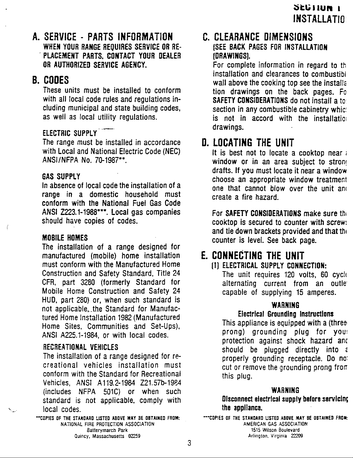
A.SERVICE- PARTSINFORMATION C.CLEARANCEDIMENSIONS
WHENYOURRANGEREQUIRESSERVICEORRE- (SEEBACXPAGESFORINSTALLATION
PLACEMENTPARTS,CONTACTYOURDEALER (DRAWINGS).
ORAUTHORIZEOSERVICEAGENCY. For completeinformationin regardto th
installationand clearancesto combustibl
B. COOES wallabovethecookingtopseetheinstall_
Theseunits must be installedto conform tion drawings on the back pages. Fo
withall localcoderulesandregulationsin- SAFETYCONSIDERATIONSdonotinstalla to:
cludingmunicipalandstatebuildingcodes, sectioninanycombustiblecabinetrywhic'.
as wellas local utility regulations, is not in accord with the installatio=
ELECTRICSUPPLY....
Therangemustbeinstalledin accordance O.LOCATINGTHEUNIT
with LocalandNationalElectricCode(NEC) It is bestnot to locatea cooktopnear;
ANSI/NFPANo.70-1987"*. windowor in an area subjectto stron!
GASSUPPLY choosean appropriatewindow treatment
Inabsenceoflocalcodetheinstallationof a
range in a domestic household must createa fire hazard.
conformwith the NationalFuel GasCode
drawings,
drafts.If youmustlocateit neara window
one that cannotblow over the unit an(
ANSI Z223.1-1988"**.Localgas companies ForSAFETYCONSIOEP,ATIONSmakesureth_
shouldhave copiesof codes, cooktopissecuredto counterwithscrew'
andtiedownbracketsprovidedandthatthl
MOBILEHOMES counteris level.Seebackpage.
The installationof a range designedfor
manufactured(mobile) home installation E.CONNECTINGTHEUNIT
mustconformwiththeManufacturedHome (1)ELECTRICALSUPPLYCONNECTION:
ConstructionandSafety Standard,Title24 The unit requires120 volts, 60 cycl_
CFR, part 3280 (formerly Standard for alternating current from an outle-
MobileHomeConstructionand Safety 24 capableof supplying15 amperes.
HUD,part 280)or, whensuch standardis
notapplicable,._theStandardfor Manufac- WARNING
turedHomeinstallation 1982(Manufactured ElectricalGroundingInstructions
Home Sites, Communitiesand Set-Ups), Thisapplianceisequippedwitha(three
ANSIA225.1-1984,or with local codes, prong) grounding plug for you_
protectionagainst shock hazard ant
RECREATIONALVEHICLES should be plugged directly into
Theinstallationof a range designedfor re- properlygroundingreceptacle.Do no:
creational vehicles installation must cut or removethegroundingprongfrorr
conformwith the Standardfor Recreational this plug.
Vehicles, ANSI Al19.2-1984 Z21.57b-1984
(includes NFPA 501C) or when such WARNING
standard is not applicable,comply with Olsconnectelectrlcalsupplybeforeservlcln_
,.... local codes, theappliance.
"'COPIEDOFTHEDTANDAROLISTEDAROVEMAYDe OBTAINEOFROM: "COPIED OFTHESTANDARDUSTEDkBOVEMAYBe ORTAINEDFROI:
NATIONALFIRE PROTECTIONASSOCIATION AMERICANGAS ASSOCIATION
Batterymarch Park 1515Wilson Boulevard
Quincy. Massachusetts 02259 Arlington. Virginia 22209
3
Page 4

[2] GASSUPPLYCONNECTION:A TRAINEO (g)Turnonmaingasvalveatmeter,and
SERVICEMANMUST MAKE THE GAS relightpilotsatothergasappliances.
INSTALLATION.
(a) AGASCUTOFFVALVESHOULDBEPUT (hi Applysoapsudstogasconnectionat
IN AN ACCESSIBLELOCATIONIN THE rangeandcheckfor leakage.Check
SUPPLYLINEAHEAOOFTHEUNIT.FOR for leakageat all gas connections
TURNINGONANDTURNINGOFFGAS and fittingsin the range.
SUPPLY.If theunitistobeconnected
tohousepipingwithflexibleorsemi- CAUTION:NEVERCHECXFORLEAKS
rigid metal connectors for gas WITHA FLAME.
appliances,CONNECTORNUTSMUST
NOTBE CONNECTEDDIRECTLYTO (i) Connectelectricsupplycordto wall
PIPE THREADS.THE CONNECTOR receptacle 120 volt 60 cycle alter-
MUST BE INSTALLED WITH hatingcurrent,at 15 amperes.
ADAPTORSPROVIDEDWITH THE BEFORELIGHTINGANYBURNER,SEE
CONNECTOR. THAT ALL PACKING MATERIALS
HAVE BEEN REMOVEDFROMTHE
(b)The house piping and/or range
connectorusedto connectthe range UNITS.
tothemaingassupplymustbeclean, F.REGULATOR
freeof metalshavings,rust,dirtand All rangesareequippedwitha gaspressure
liquids(oil or water). Dirt,etc. inthe regulatorfor controllingand maintaininga
supplylines can work itsway into uniformgaspressureinthegasmanifoldof
therangemanifoldandinturncause the unit.Theburnerorifices,etc.,aresized
failure of the gasvalvesor controls for gas pressure delivered by the
and clog burners and/or pilot REGULATORSUPPLIED.IT MUSTNOTBE
orifices. REMOVED.
(c)Turnoff allpilotsand maingasvalve i_ / I
of other gas appliances. ( /, ,EAR OFUNIT
/
J
(d)Turn off maingas valve at meter. _PHESSURE
(e)Before connecting the unit, apply I---t---ARHOWSHOWS
pipe thread compoundapprovedfor _L r FLOWOFGAS
LPGto all threads. =]
==,,,,,,J
FIGURE1
(f) Connectunit to gas supply. Use a The gas pressure regulator for the top
backupwrenchwhentwisting onend section (seefigure 1)is locatedin thepack
of manifold. CAUTION:MAKESURE out box for shipment.The burner orifices,
THECONNECTIONDOESNOTSHIFT etc.,aresizedfor thegaspressu_redeliverr "
THE MANIFOLD PIPE OUT OF by the regulator supplied - IT MUSTBc
POSITION.THISCOULDCAUSETHE INSTALLED before operating the to_
VALVE HANDLESAND KNOBSTO section. For convenience of service, it
BIND. shouldbeinstalled as shown in figure 1,ol
4 in an accessiblelocation.
Page 5

G.SEALEOBURNER H.CHECKINGMANIFOLOGAS
-(a)Removableporcelainizedcast iron burner PRESSURE
cap with Iocatorpin. tf it should be necessaryto check th
To replacethe burnercap: Insert the manifoldgaspressure,connectmanomete
Iocator pin into the stot in the burner (watergauge)or other pressuredevicetl
base. The burner will not operate the top burner orifice farthest from th_
correctly if the cap is not replaced manifoldinletandturn burnervalve on.Se,
properly, figure 2. For an accuratepressure chec_
have at least two (2) other top burner.,
(b) Removableporcelainized steel trim burning. Be sure the gas supply (inlet
ring. pressureis at least one inch (1") abov,
(c) Non-removablealuminumburnerbase. specifiedrangemanifoldpressure.The ga.'
supply pressureto the regulatorshouh
(d)Ignitor. neverbeover14inchesW.C.Whenproperl,
adjusted for Natural Gas-the manifoh
pressureis4"W.C.,for LPGasthe pressur,
(e) Gastube opening, is 10"W.C.
(f) Locatorslot for Iocator pin in black
removableburnercap. I. CHECKING PRESSURE OF HOUSE
PIPINGSYSTEM
( _ f__.. _ (1)Theapplianceand its individualshutof
A--_ _ES_ valve must _oedisconnectedfrom th,
__;________ pressuretesting of that systemat tee
__o_- (13.8in. W.C.).
FIGURE2 individual manualshutoff valve durin!
gas supply piping system during an!
pressuresin excessof 1/2 Ibs./sq. ir
(2)Theappliancemustbeisolatedfrom th,
gassupply pipingsystemby closing it:
any pressuretestingof the gassuppl'
pipingsystemattestpressuresequalt,
or less than 1/2 Ibs./sq. in. (13.8 in
W.C.).
5
Page 6

SECTIONII
AOJUSTMENTS
A.TOPSECTION- ELECTRICIGNITION B.TOPBURNERADJUSTMENT
To operate,pushandturntopburnerknob HIGH-MEg-WARMVALVE:
to the LITE position.The top burnerwill (1)Theburnerflameat theWARMposition
light, shouldextendtotheouteredgeofthelip
of the burnercap. The WARMsetting
To turnOFFsparkafter thetopburnerhas shouldbe suchthat a stableflame is
ignited: maintainedon the burnerwhenturning
the knob from HIGHto WARM. If it
(1) For rangeswith HI-SIM-WARMvalves, shouldbe necessaryto increaseor
turn knob,eitherdirectionto HI setting, decreasetheflameattheWARMsetting,
figure3. operate burner at HIGH positionfor
. approximatelyfive minutes.Turn knob
(2) Thereare separateignitiondevicesfor to WARM(seefigure 3). Removevalve
eachburner.Theseignitorsare turned handleand with a small screwdriver
"on"whenanyknobisturnedto theLITE makethedesiredadjustmentbyturning
setting.Theignitorswill"spark"aslong adjustmentscrew locatedin centerof
asanyofthetopburnerknobsareatthe valvestem.Checkeachtopburneratthe
LITE setting. In case of an electrical _ : WARMi_osit!onfor flam'esize.
powerfailure,the top burnerscanstill
beused.Tolighta burner,holdalighted _ C
to be usedandturnvalveknobfor the
burnerto LITE.USEEXTREMECAUTION.
• kitchenmatchadjacenttothetopburner _
Theelectricignitorwillnotcome"on". It
isnecessarywhenusingthetopburners FIGURE3
during this type of emergencyto light
eachburnerto be usedwith a kitchen
matchasdescribedaboveeachandevery (2)MED(MEDIUM)isanintermediatesetting
timetheburnerorburnersaretobeused. andthereis noadjustmentto bemade.
NOTE: There are no air shutter
adjustmentsto be madewith thistype
burner.
HI-SIM-WARMKNOB
6
Page 7

INSTALLATIONDRAWINGS
A. CLEARANCESTOCOMBUSTIBLECONSTRUCTION
3 inchesminimumto anycombustibleside wail. TheseunitscanbeinstalledinacaOinetmadeofwoodorother
combustiblematerial.
Maximumdepthof cabinetsinstalledabovecooktnpto be13
inches. "The30 inchdimensionmaybereducedto not lessthan24
inches when the wail cabinetsin a domestichomeare
6inchesminimumspacing betweenindividualtopsections ina protected with fireproof materials in accordance with
dual installation. AmericanNationalStandards1723t-1988or inmobilehomes
,_,. whentheyare protectedwithfireproofmaterialsinaccordance
comb Standards,"iitle 24 CFR,Part 3280(formerlythe Federal
""_=----_i__ with the ManufacturedHome Constructionand Safety
Wall
HUO(Part2801.
=1| _L__ Standardfor MobileHomeConstructionand Safety,Title 24,
ml3ust_ble
designedto withstandtheheatproducedby thenormalsafe
operationof a listedappliance.Discolorationordamage,such
-... as delamination,may occur.
_M_ wa, CAUTION:Some cabinetsand buildingmaterials are not
- _ J PrOVide for_ etectn¢ (cJfounOe131
_ / OUt_ I_tet" ot CABINET
BELOW RANGE.
-I
' 30"WITHPORCELAINTOP_ 3inchesminimumtoanycombustiblesidewall.
Maximumdepthofcabinetsinstalledabovecooktopto be13
inches.
,:- .Ax. dual installation.
- t4]_N.
COH@UST IBLE
'_._LL,
2'5" t,,ICtR_ L
CABINET TOP DEPTN
30" MIN. C_H_US T_.gLE
3" HIN,
OF CABINET I
/-
PROVII_E ;QR _O VAC "
ELECTRIC OUTLET
( C_OUNOED I IN I_ _
CENTE_ OF CABINET CF CAglNET _
BE'I_Cw COO_TOP.
m
6inchesminimumspacingbetweenindividualtopsectionsina
WAL_.
18" M]._I.
30"WITHGLASSTOP
7
Page 8

CCMBUSTIBLE
WALL
CO_USTIBLE
"_ WALL
36" WITH GLASS TOP 3 inchesminimumto any combustiblesidewail.
B.CUTOUTOIMENSIONS
_eMINIMUM TO ANY COMBUSTIBLE
WALL ABOVE COOETOP.
Maximumdepthof cabinetsinstalledabovecooktoptobe
inches.
6inchesminimumspacingbetweenindividualtopsectionsin
dualinstallation.
_Z 3 3/8" Depth
• Regulator sullied with "_' "lb _-" //
_'wt _ shutoff voive must MIN. _ _ .........
;_mron. ' /'--*3 7/8"
30" WITHPORCELAINTOP M,.
8
 Loading...