

Maytag CMV1000BAQ, CMV1000BAW, CMV1000ADW, CMV1000ADB, CMV1000ADA Installation Instructions
...Page 1
Introduction
Your Over-the-Range microwave oven comes complete with an installation instruction kit which
contains the following three pieces of information required to install it.
I. This installation instruction
booklet, complete with Ill. Instead of The Wall Mount NOTE:
diagrams on preparing your Template, Wall Mounting IT IS RECOMMENDED
cabinets and microwave oven Plate, used to locate the THAT TWO PEOPLE
for installation, mounting plate holes and to INSTALL THIS PRODUCT.
locate the horizontal exhaust
II. The Top Cabinet Template, location. IMPORTANT:
used to locate the power cord Please read all of the KEEP INSTRUCTIONS FOR
clearance hole, cabinet instructions thoroughly before LOCAL ELECTRICAL
mounting holes and the installing your microwave INSPECTOR'S USE.
vertical exhaust location, oven.
Important Safety Information
This appliance must be grounded. In the
event of an electrical short circuit, grounding
Grounding Instructions
reduces the risk of the electric shock by /
providing an escape wire for the electric
current. This appliance is equipped with a __
cord having a grounding wire with a
grounding plug. The plug must be plugged
into an outlet that is properly installed and
grounded.
WARNING - Improper use of the grounding
can result in a risk of electric shock.
accept the plug on the appliance. The marked
Consult a qualified electrician or serviceman ff rating of the extension cord shall be equal to or
the grounding instructions are not completely greater than the electrical rating of the appliance,
understood, or if doubt exists as to whether the or DO NOT USE AN EXTENSION CORD.
appliance is properly grounded, and either:
2) If the power supply cord is too short, have a
1) If it is necessary to use an extension cord, use qualified electrician or serviceman install an
only a 3-wire extension cord that has a 3-blade outlet near the appliance.
grounding plug, and a 3-slot receptacle that will
Page 2
Safety Instructions POUNDS.
This product requires a three prong grounded PRODUCT CANNOT BE INSTALLED TO
receptacle. The installer must perform a ground CABINET ARRANGEMENT'S SUCH AS AN
continuity check on the power outlet box before ISLAND OR A PENINSULA. IT MUST BE
beginning the installation to insure that the MOUNTED TO BOTH A TOP CABINET AND
outlet box is properly grounded. If not properly A WALL.
grounded, or if the outer box does not meet the
electrical requirements noted, (under
ELECTRICAL REQUIREMENTS), a qualified Electrical Requirements
electrician should be employed to correct any
deficiencies. Product rating is 120 volts AC, 60 Hertz, 13.5
CAUTION: FOR PERSONAL SAFETY, connected to a supply circuit of the proper
REMOVE HOUSE FUSE OR OPEN CIRCUIT voltage and frequency. Wire size must conform
BREAKER BEFORE BEGINNING to the requirements of the National Electric
INSTALLATION TO AVOID SEVERE OR Code or the prevailing local code for this
FATAL SHOCK INJURY. CAUTION: FOR kilowatt rating. The power supply cord and
PERSONAL SAFETY, THE MOUNTING plug should be brought to a separate 20 ampere
SURFACE MUST BE CAPABLE OF branch circuit single grounded receptacle. The
SUPPORTING THE CABINET LOAD, IN outlet box should be located near the cord entry
ADDITION TO THE ADDED WEIGHT OF point. The outlet box and supply circuit should
THIS 85 POUND PRODUCT, PLUS be installed by a qualified electrician and
ADDITIONAL OVEN LOADS OF UP TO 50 conform to the National Electric Code or the
POUNDS OR A TOTAL WEIGHT OF 135 prevailing local code.
CAUTION: FOR PERSONAL SAFETY THIS
amps, and 1.45 kilowatts. This product must be
Power supply cord
a) A short power-supply cord is provided to reduce the risks resulting from becoming entangled
in or tripping over a longer cord.
b) Longer cord sets or extension cords are available and may be used if care is excised in their use.
c) If a long cord or extension cord is used:
1) The marked electrical rating of the cord set or extension cord should be at least as great as
the electrical rating of the appliance.
2) The extension cord must be a grounding type 3-wire cord, and
3) The longer cord should be arranged so that it will not drape over the counter top or
tabletop where it can be pulled on by children or tripped over unintentionally.
This over-the-range oven was designed for use over ranges no wider than 30 inches. It may be
installed over both gas and electric cooking equipment.
2
Page 3

Installation Hardware
A_-_'-_ _ _'.--._..m-':_I
*. *_*_------_WALLTEMPLATE * * *=_=
IllI_] TOP CABINE-_TEMPLATE FI+_']IIII}_...,_*_'_";_
The following is a list of parts Parts List Tools
you may need for installing 1. Lag screws 1/4" × 2" ( 3 The following tools may be
your Over-the-Range EA ) needed for installation of your
microwave oven. You will find 2. Toggle Bolts 3" ( 3EA ) microwave oven.
them packaged inside the 3. Spring Loaded Toggle Nuts PhiUips screwdrivers, Electric
microwave cooking cavity. ( 3 EA ) Drill Motor, 1/2" & 5/8"
Remove all parts from the 4. Cabinet Mounting Bolts Wood Bits &3/16" Drill Bit,
oven cavity and compare them 1/4" x 3-1/8" ( 3 EA ) Saw to cut exhaust opening, (if
with the parts list and 5. Washers 3/4" ( 3 EA ) needed) or Jig Saw, Tin Snips
illustration to be sure that 6. Grommet (if needed), Pencil, Tape
none are missing. Use this 7. Damper Measure, Paper Tape & Duct
time to become familiar with 8. Foam Tape ( 2 EA ) Tape.
each piece. 9. Top Cabinet Template
10. Wall Mount Template
3
Page 4
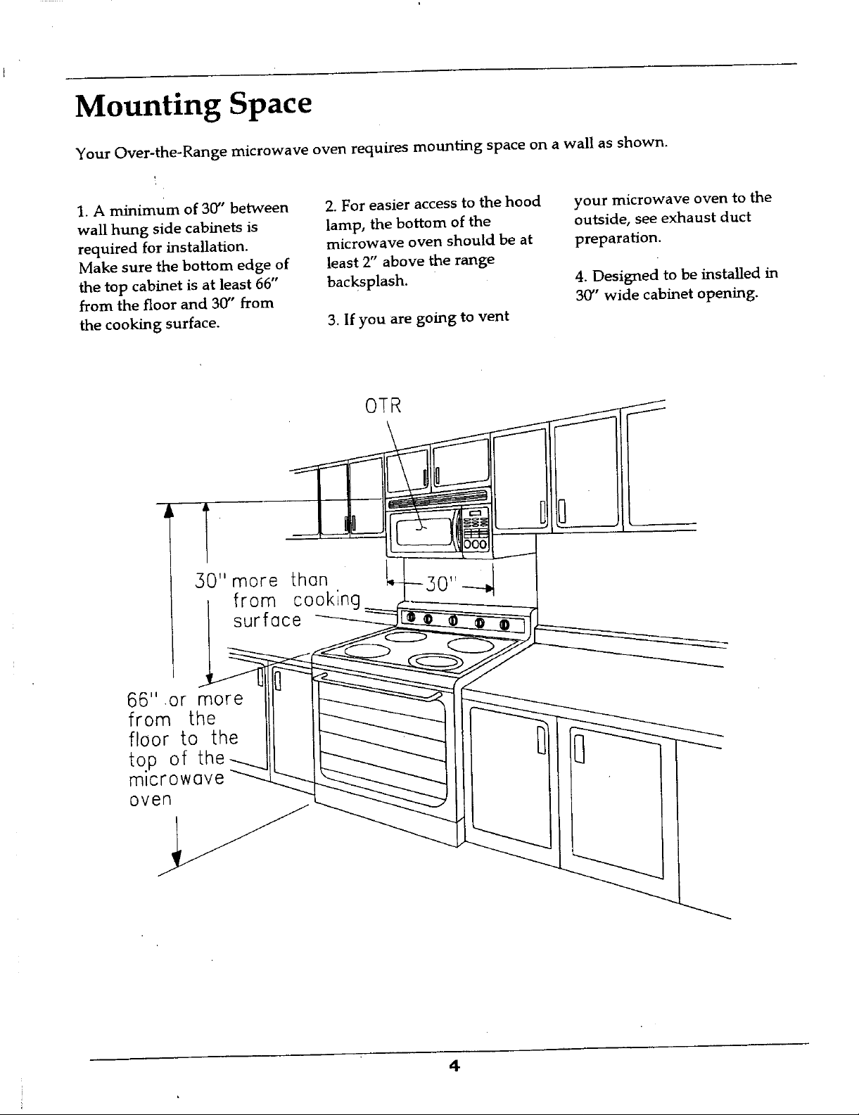
Mounting Space
Your Over-the-Range microwave oven requires mounting space on a wall as shown.
.
1. A minimum of 30' between 2. For easier access to the hood your microwave oven to the
wall hung side cabinets is lamp, the bottom of the outside, see exhaust duct
required for installation, microwave oven should be at preparation.
Make sure the bottom edge of least 2" above the range
the top cabinet is at least 66" backsplash. 4. Designed to be installed in
from the floor and 30" from 30" wide cabinet opening.
the cooking surface. 3. If you are going to vent
OTR
I
30" more than
from
surface
66" or more II- i
from the II
floor to the II I II__
top of theL-__i I
om_Cr#wove _
4
Page 5
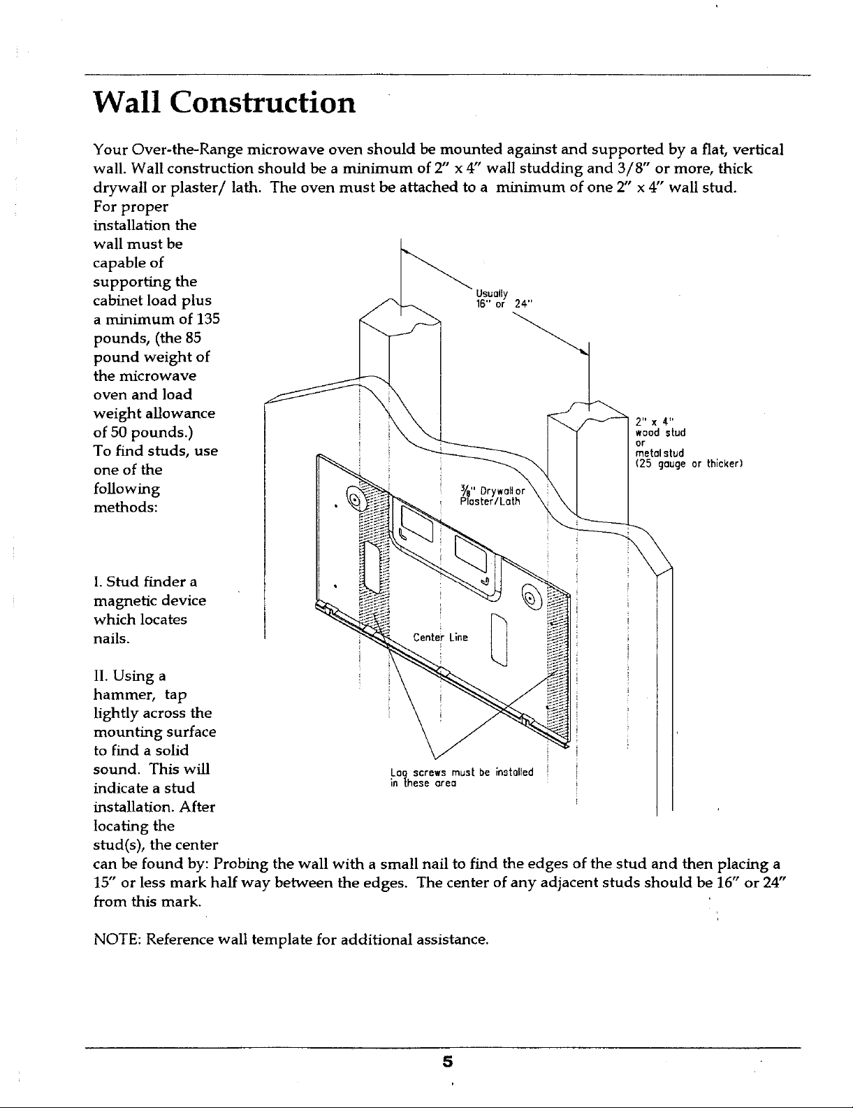
Wall Construction
Your Over-the-Range microwave oven should be mounted against and supported by a flat, vertical
wall. Wall construction should be a minimum of 2" x 4" wall studding and 3/8" or more, thick
drywall or plaster/lath. The oven must be attached to a minimum of one 2" x 4" wall stud.
For proper
installation the
wall must be
capable of
supporting the
cabinet load plus 16"or 24"
a minimum of 135
pounds, (the 85
pound weight of
the microwave
oven and load
weight allowance 2" x 4"
of 50 pounds.) ,ood stud
To find studs, use metalstud
one of the (25gaugeorthicker)
following s,"B"Drywa,o,
methods: Plaster/Lath
Usually
or
1.Stud finder a
magnetic device
which locates
nails.
lI. Using a
hammer, tap
lightly across the
mounting surface
to find a solid
sound. This will Log screws mustbeinstalled
indicate a stud inthesearea
installation. After
locating the
stud(s), the center
can be found by: Probing the wall with a small nail to find the edges of the stud and then placing a
15" or less mark half way between the edges. The center of any adjacent studs should be 16" or 24"
from this mark.
NOTE: Reference wall template for additional assistance.
Page 6
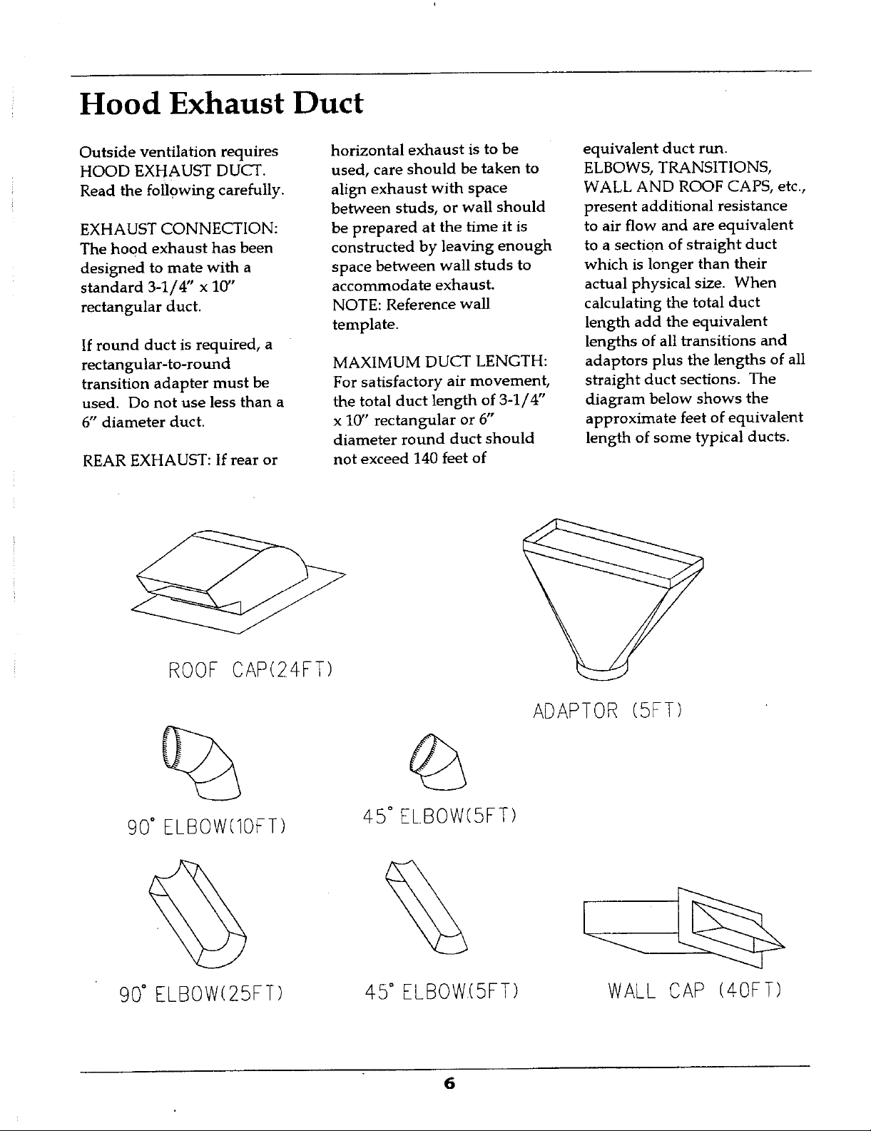
Hood Exhaust Duct
Outside ventilation requires horizontal exhaust is to be equivalent duct run.
HOOD EXHAUST DUCT. used, care should be taken to ELBOWS, TRANSITIONS,
Read the following carefully, align exhaust with space WALL AND ROOF CAPS, etc.,
between studs, or wall should present additional resistance
EXHAUST CONNECTION: be prepared at the time it is to air flow and are equivalent
The hood exhaust has been constructed by leaving enough to a section of straight duct
designed to mate with a space between wall studs to which is longer than their
standard 3-1/4" x 10" accommodate exhaust, actual physical size. When
rectangular duct. NOTE: Reference wall calculating the total duct
template, length add the equivalent
If round duct is required, a lengths of all transitions and
rectangular-to-round MAXIMUM DUCT LENGTH: adaptors plus the lengths of all
transition adapter must be For satisfactory air movement, straight duct sections. The
used. Do not use less than a the total duct length of 3-1/4" diagram below shows the
6" diameter duct. x 10" rectangular or 6" approximate feet of equivalent
diameter round duct should length of some typical ducts.
REAR EXHAUST: If rear or not exceed 140 feet of
ROOFCAP(24FT
ADAPTOR(5FT)
90° ELBOW(lOFT) 45° EL.BOW(SFT)
90° ELBOW(25FT) 45° ELBOW(SFT) WALL CAP (4OFT)
Page 7
Ventilation System Instructions
Your Over-the-Range microwave oven is designed for adaptation to the following three types of
ventilation. Select the type of ventilation required for your installation and proceed to the
appropriate section.
A. Horizontal Ventilation System
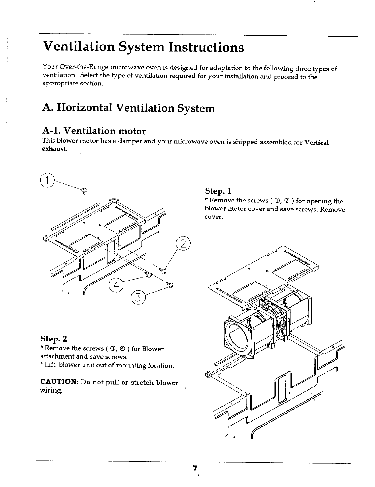
A-1. Ventilation motor
This blower motor has a damper and your microwave oven is shipped assembled for Vertical
exhaust.
Step. 1
blower motor cover and save screws. Remove
cover.
j_ i * Remove the screws ( 0, (2)) for opening the
Step. 2
* Remove the screws ( @, ® ) for Blower
attachment and save screws.
* Lift blower unit out of mounting location.
CAUTION: Do not pull or stretch blower
wiring.
7
Page 8
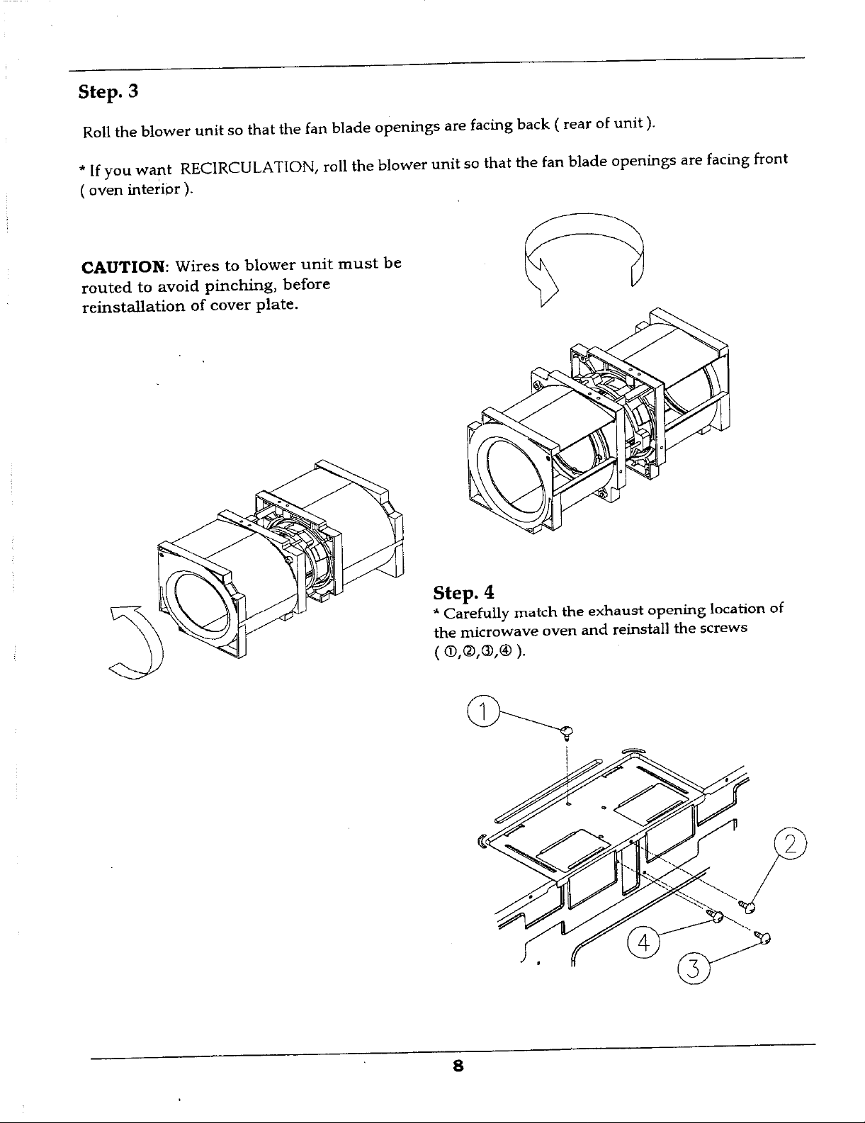
Step. 3
Roll the blower unit so that the fan blade openings are facing back ( rear of unit ).
* [f you want RECIRCULATION, roll the blower unit so that the fan blade openings are facing front
( oven interior ).
CAUTION: Wires to blower unit must be (_,A " /__
routed to avoid pinching, before
reinstallation of cover plate.
Ste
• and reinstall the screws
ih_i_!c_!_t_hv:he exhaust opening location of
8
Page 9
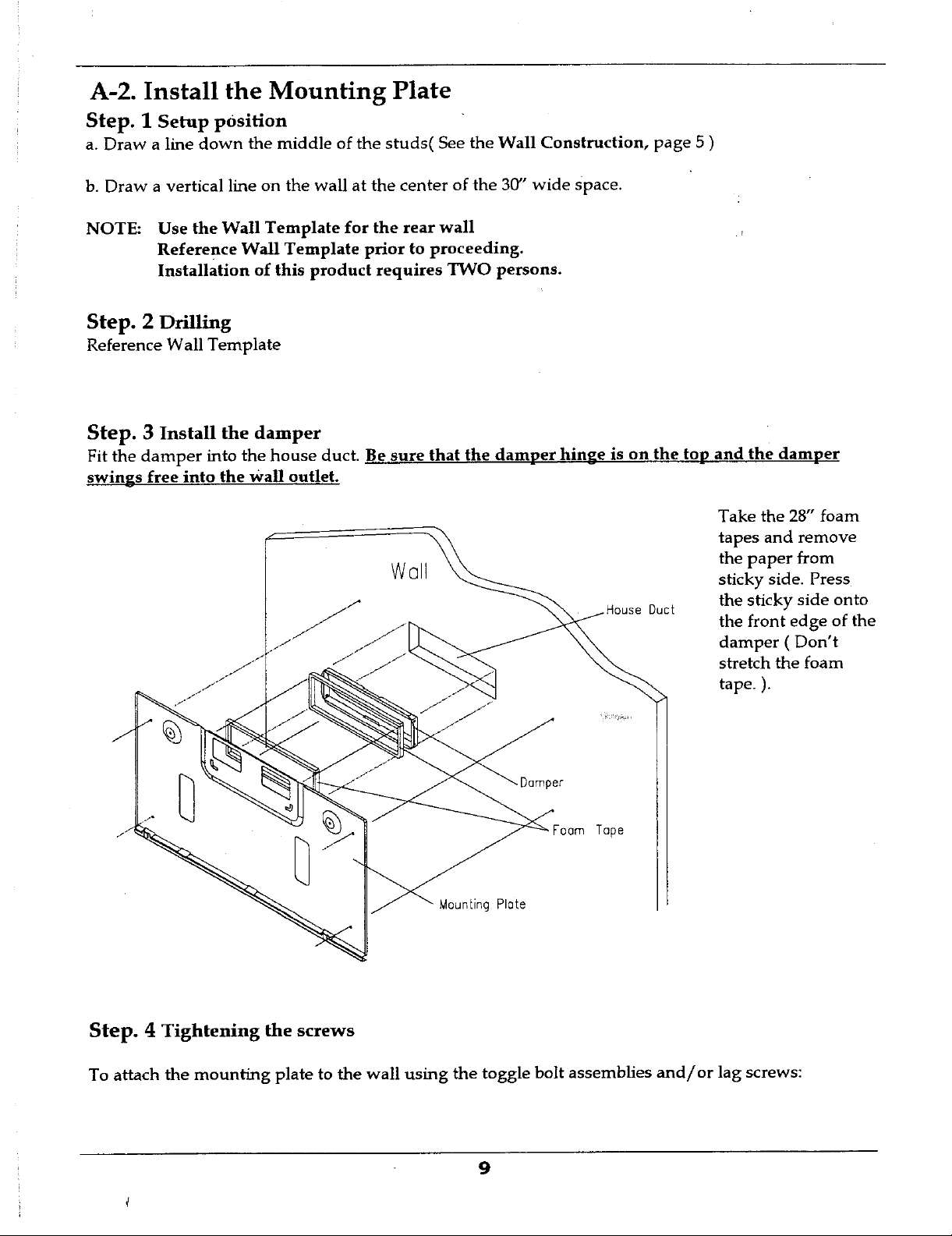
A-2. Install the Mounting Plate
Step. 1 Setup position
a. Draw a line down the middle of the studs( See the Wall Construction, page 5 )
b. Draw a vertical line on the wall at the center of the 30" wide space.
NOTE: Use the Wall Template for the rear wall
Reference Wall Template prior to proceeding.
Installation of this product requires TWO persons.
Step. 2 Drilling
Reference Wall Template
Step. 3 Install the damper
Fit the damper into the house duct. Be sure that the damper hinge is on the top and the damper
swings free into the Wall outlet.
Take the 28" foam
-- \ tapes and remove
the paper from
W@11 sticky side. Press
//"/"/ .HouseDuct the sticky side onto
./ damper ( Don't
" stretch the foam
/ _"/" tape. ).
the front edge of the
Step. 4 Tightening the screws
To attach the mounting plate to the wall using the toggle bolt assemblies and/or lag screws:
9
Page 10

Spacing more than I a. Insert toggle bolts through mounting plate at required locations
Wallthickness _ and add the spring loaded toggles.
c. Next, secure mounting plate to the wall
by tightening toggle bolt assemblies or lag
screw(s).
(Remember, you must have at least one lag
screw into a wall stud.) For stud location
refer to WALL CONSTRUCTION
see page 5 Dry wall
Reference wall template prior to proceeding.
Be sure you leave space at least the thickness of the wall between
the mounting plate and the end of the toggle nut, (in closed
position). If you do not leave this space, the toggle nut will not
open on the other side of the wall.
b. Position mounting plate on wall and insert toggle bolt
assemblies through the drywall holes or start the lag-screw(s)
through the wall stud(s).
Mounting plate
d. Tighten the lag screw(s) into wall
studs(s); Do not over tighten.
A-3.Mounting microwave oven
NOTE:IT ISVERYIMPORTANTTHATTHISOVENBEINSTALLED
10
Page 11
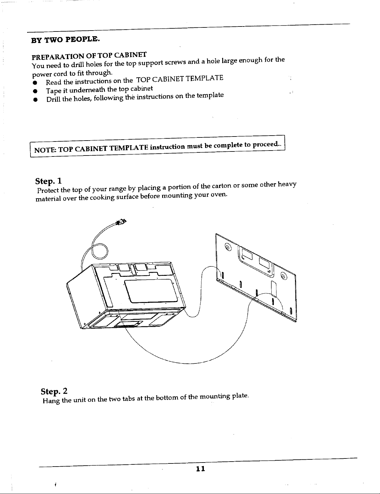
BY TWO PEOPLE.
PREPARATION OF TOP CABINET
You need to drill holes for the top support screws and a hole large enough for the
power cord to fit through.
• Read the instructions on the TOP CABINET TEMPLATE
• Tape it underneath the top cabinet
• Drill the holes, following the instructions on the template ,_
I NOTE: TOP CABINET TEMPLATE instruction must be complete to proceed.. I
Step. 1
Protect the top of your range by placing a portion of the carton or some other heavy
material over the cooking surface before mounting your oven.
Step. 2
Hang the unit on the two tabs at the bottom of the mounting plate.
11
Page 12

Step. 3
Thread power cord through the
hole at the bottom of the top
cabinet. Swing the unit upward
to meet the top ofthe mounting
plate and hold secure.
Step. 4
Insert the 2 bolts through 2
cabinet floor. Tighten screws
to close the gap between top
__ fiat washers into holes on top
_ NOTEI MICROW2_VEOVEN MUST BE SECURED
cabinet and the microwave
oven.
WITH TWO MOUNTING
BOLTS.
Dress power cord neatly in
top cabinet.
Install the grease filters on
bottom of microwave unit.
12
Page 13

* Using filler block for recessed bottom cabinet
Insert a bolt, with a 3/4" washer into one of the holes drilled previously in the top
cabinet floor. ,'
(D & E on Top Cabinet Template.)
top cabinet washer
mounting screw /
Cabinetfront_1_\ Cabinet bottom shelf
microwave lock
oven top
13
Page 14

B. Vertical Ventilation System
B-1. Ventilation motor
This ventilation motor has been assembled for vertical exhaust.
B-2. Install the mounting plate
See the page 9, A-2. Install the mounting plate.
• You need not perform the step2 and step 4; Horizontal ventilation only.
B-3. Mounting Microwave oven
See the page 11, A-3.Mounting the Microwave oven.
B4. Install the Damper
For the vertical exhaust open the top
cabinet and attach the damper to the
microwave through the cabinet bottom. For
front to back or side to side adjustment,
slide the damper as needed.
With the damper out, twist the damper to
fit under the flaps of the blower plate.
Replace the damper and make sure it will move easily by the force of the exhaust air.
Be sure to square the comers on the hinge ends.
After the microwave oven is installed, Pull the house duct down to connect to the
damper.
microwave unit.
__ Install the grease filters on the bottom
14
Page 15

C. Recirculation Ventilation System
Your over the range microwave oven has been provided with a charcoal filter for a
recirculation venting application. If replacement of the charcoal filter is required,
contact your MAYTAG authorized dealer.
C-1. Ventilation motor
See the page 7, A-1. Ventilation motor, step 3
C-2. Install the Mounting plate
See the page 9, A-2. Install the mounting plate.
• You need not perform the step2 and step 4; Horizontal ventilation only.
C-3. Mounting Microwave oven
See the page 11, A-3. Mounting the Microwave oven.
*You need not use damPer for recirculation.
C-4. Install the Charcoal filter
ChorcoolFiller
*Remove the screws on the front of the grille and remove the grille.
*Install the charcoal filter.
*Replace the grille and screws.
*Install the grease filters on the bottom microwave unit.
15
Page 16

Checklist for Installation
1. Make sure oven has been installed according to these instructions, top cabinet
template and wall template.
2. Remove all packing material from the oven.
3. Plug in power cord.
4. Read Use and Care manual. • ,
5. Keep installation instructions and template for the local electrical inspector s use.
16
Page 17

i ,n
WARNI_-
Bec_cShockHazard
Locateanyelectricalcircui
.... lilac,c0uldbe affectedI_
" "ns_lat_ o" " product
" Caremustbe"takenwhe
drillingholes.EIec'_wir,
maybeconcededbeh.ind
coveringandC_t_tv,_th
0 -. rt,.m._,_G'_a,t_ _ _ __"_ _
couldresultinelectrical
A
ifhS':":"p0JntJs0verawallstud, Fa/luretof_ow theseinst_
Usealagscrew s_,._ _,_
o o o
0 0 0 O - -....©.:. 0''_
i IIII "
CAUTION
INSTALLATIONOFTHISPRODUCT
REQUIRESTWOPERSONS.
I',
Page 18

Elecfi'i¢ShockHazard
Locateanyelectri_drcuits
thatc(x_be_fectedby
mustbetakenwhen
•drillingholes,Bed_cal,.wires
maybeconcea_bettedw_1
coveringand_with _em-
:aJfuretofo/rowtheseins_ctions
couldresultinelectrical
shockoroltlerpersonalinjury.
I' I O_ V,IIALL--r
ifthispointisoverdrywall,
O_"_ E Drilla 5,8"dia.hole
Useatogglebolt
, ........ __MINIMUM30
'- --'o o o CEI
INSTALkATI
ifyoucontacta wallstudatanyoftheselocations,
a lag screwwillbe installedatwall
STEP1.Drill*"diameterholesatA,B,C and D.
NOTI_:t_no sTUdlocatedatA,B,C orD,insert
stud location.Ifno stud is contactedat!ocations
A,B,C and D ;Dr,!l*"
diameterhoL-_torinstallationoftogglebolts•
a minumumofonelag screwintowallstudatany
locationindicatedby E.
Page 19

LL TEM!
/
rilla 5_"dia.h01e |
thispointisoverdnjwall,
Iseatoggleb01t
INSTALLATIONINSTRUC
diameterholesatA,B,C and D. STEP3.Remove
,ucontacta wallstud atanyoftheselocations, then
lg screwwillbe installedatwall install
' "ation.Ifno studis contactedatlocations NOTE:TOPC,_
_,_ andD ;Dri!l*" STEP4.Hangt
"neterhoJ_torinstallationoftogglebolts. I the
[ud locatedatA,B,C orD,insert I SE[
linumumofonelag screwinto wailstudatany I STEP5.Thread
ltion indicatedby E. (_ atth_
Page 20

" ormorefr,
66"
•. E ,,,t
/!PLA--_--
Dnl
'. DI::(31IIDEI'3
I. I I.I_/UI. ,LU _....
Eo o <F
:IUCTION L_
Removethewalltemplateandposition
themicrowavemountbracketoverthedrilledholes,
installbracketwithlag screwsand/ortogglebolts.
TOPCABINETTEMPLATEinstructionmustbe completeto proceed.
. Hangtheuniton thetabsatthebottomof
themountingplate.
SEETHEINSTALLATIONMANUAL,PAGE11- 12
Threadpowercordthroughthehole /-_--,-_"
atthebottomofthetop cabinet.,swing
theunitupwardto mcctthewallandtop cabinet.
L _ I,..I .......
Lgl
Page 21

I' _ . t'°°_'°e
I
ormorefrom thefloor.
..... . ...... .-::-_: : - _ . -
fromthe cookingsurface.
E Drilla 5,8"dia.hole Drilla 316'dia.hole
ifthispointisoverdrywall, ifthis_intisoverawallstud,
Useatogglebolt Usealagscrew
©
\
C '_O 0 0 O 0
I,,.,.,""--
Page 22

U/-_UIILII_
INSTALLATIONOFTHISPRODUCT s,
REQUIRESTWOPERSONS.
N
'ffthispointisoverawallstud,
B Drilla 3,16"dia.hole s
Usealagscrew
o o o 01---
Drilla
ilthisp0i
Useatc
Page 23

STEP1.Drill*"alarn_t_,,,.,,oo,.,,..,-, -
ifyoucontacta wallstudatanyoftheselocations, I
a lagscrewwillbe installedatwall ,- .
studlocation.Ifnostudiscontactedat!ou__t_ons
A,B,C andD ;Drill*"
diameterbo_ _'orinstallationoftogglebolts. I
NOTI_:-;fno stud locatedatA,B,C orD,insert
a minumumofonelagscrewintowallstudatany
locationindicatedbyE.
STEP2.(skipforverticalexhaustinstallation)
Forhorizontalexhaustinstallation,
Cutopeningforexhaustatshadedlocation
marked"OUTSIDEEXHAUST(HORIZONTAL)".
mountbracketto contacthorizontalducting.
Attachfoamtapeto backsideofmicrowave
I
o o
I
_lnsert a minimum of one (1)la
_ ThisovenMUS.Tbeconn.ect_
"t! a _."dia,h01e _ - thisis a minimumrequlrem
tr[hlSp01ntIsoverdrywall. "O O O (
Useatogglebolt Connectmarksto as
i lu i ii
Page 24

themicrowavemountDrac_uLuv_J_,,_,.,,,,,,......... ,
installbracketwithlagscrewsand/ortogglebolts.
NOTE:TOPCABINETTEMPLATEinstructionmustbe completeto proceed.
STEP4.Hangtheuniton thetabsatthebottomof
] themountingplate.
SEETHEINSTALLATIONMANUAL,PAGE11- 12
STEP&Threadpowercordthroughthehole
atthebottomofthetop cabinet,swing
theunitupwardto mcctthewallandtop cabinet,
holdsecure.
STEP6.Placewashersonthetop cabinet
Secureboltsto microwavecabinet.
I
(1)lagscrewinto a wallstud in
"onnecteatoatleastonewallstud
eauirement.
s to as manystudsas possible.
I
o o
Page 25

holes,
)olts.
"ompleteto proceed.
1,- 12
#inet,
Drilla 3,16'dia.hole
o o
:0 0 Usealagscrew 0
E over
Drilla 58'clia,h01e
ifthispointisoverd_all.
Useatogglebolt O
i i ill i
Page 26

0 0 0 0
C@
Drilla 3,16"dia.hole
ifthispoin!isover
awallstud.
--------0 0 Usealagscrew 0 0
"_ia.hole
s_erdrywall.
lebolt 0 0
_J
o
Page 27

Drill 5_,, (15.875mm) die. hole
D
fillerblock
usefillerblockwhen
cabinetbottomis
recessed.
--01
WARNING
-- _ic Sh_ Hazard
6,mm installpowersupplycord
0,/4.. bushingaroundholedrilled
127mm Inmetalcabinet.
,9:,meFailureto followtheseinstructions
couldresultin electrical
2_.,mm shockorotherpersonalinjury.
31.8mm
%
i 10 i
i
Page 28

BINF
CA -
I •
top cabinet
cemp .
¢entelr line
Smooth riot bottom cobinet Recessed bottom cobinet
-CEN1
I
Cutoutthisar_
ifventinc.
Page 29

IET T MPL
" ,# _' _ _..-
fi,,,rb,ocks'k/ NSTALUREQI
_binet I Filler block
CENTERLINE
S
utoutthisai'eaofuppercabinetbottom _
ifventingthroughtheroof. _
I,--
C:)
O._j _
Page 30

i ii ii
Drill 5_,,(15.875mm) dia. hole
ii i
ATE E
CAUTION fillerblock
_,TIONOF THIS PRODUCT
31RES TWO PERSONS.
i i
NSTALLATIONINSTRUCTIONCutout2"dia.hole
i
Powersupplycordh01e
_TEP1. Cut the edges of the template at A,B and C, to r u_
•fit in the recessed bottom of the top
cabinet so that template willie flat
r--
cutout 2 "(50.8ram)diameterhole
for powercord at F _ _'
Cut opening f_r ,,,_.{_-_texheustlocation. /t
against the top cabinet. __ _ _
_TEP4. Remove the top cabinet template. _ 6.4m_
STEP5. Attach the filler blocks so that the holes _/,
in each block line up with the corresponding
holes in the cabinet. The filler blocks should - 12.7m
be at the same levels as the bottom edge "Forrnetalcabim3t;putttletape O_z"
of the top cobihet. . onedgeofholeto protect
fromdamage
1 "
31._
Page 31

- v4,, bushingaroundholedrilled
__|_2._m metalcabinet.
--I- -[-_,, in
'--,9._m_Failureto followtheseinstructiow
-----_,, couldresultin electrical
__ __ .25._J_mr_shockorotherpersonalinjury.
, 1
i , 31.8mm
I II
_ 12.;
i
--'----- 6.4mm OVa,
-- -- II
i
1 11
:4
Page 32

drilled
jctions
trical
_1injury.
• 31.8
' 19.1mm. .1
12.7mm 0_/4,, r/I/II/II//IHHH/H/H_'_f_HHHHH/"'''"''"""''''"''" .................
.4-mm 01/2"
t/,,-
,..1
.._.:,- _-':.,:.,,_3_".,.:._ - , ;" ±-
-': i:"
Page 33

Page 34

in eoch block rne up with the corresponding
holes in the cobinet. The filler blocks should • . .-..
be otthe same levels os the bottom edge "'Formetalcabihetputthetape
Oz
of the top cobihet. " onedgeofholeto pr(Xect
m_ p_d fromdamage
_..It.i.J
.r,.,'
/
Page 35

_ith the corresponding
:he cabinet The filler blocks should _ .-..-. _-__-
: some levels as the bottom edge "'For_cabi_c, puttt_etape 0 w,
,p cobihet, onedgeofholetoprotect
powercordfromdamage 19.! rn_
0-_4"
" 25.4 m n
1 "
31.8rr _n
11/4,'
• I
. . _.
i "
[.
1
 Loading...