

Maytag CHG9800BAE, CRG9830CAE, CRG9830CAM, CHG9830BAB, CHG9830BAE Installation Instructions
...Page 1
INSTALLER: LEA VE THESE INSTRUCTIONS WITH THE APPLIANCE.
PLEASE KEEP THIS MANUAL FOR FUTURE REFERENCE.
The manual is intended to assist in the initial installation and adjustments of the range.
GAS INSTALLATION MANUAL
SEALED TOP BURNERS
30" WIDE SELF-CLEAN
FREE-STANDING AND SLIDE-IN RANGES
INDEX
I. INSTALLATION ............................................................................ 2-5
A. Service- Parts Information ................................................................... 2
B. Codes- Electric,Gas,MobileHome,RecreationalVehicles.......................................... 2
C. ClearanceDimensions ....................................................................... 2
D. Locatingthe Range ......................................................................... 2
E.Anti-Tip DeviceInstallationInstructions.......................................................... 3
Step 1- Locatingthe Bracket.................................................................. 3
Step 2 - Anti-Tip Bracket Installation ............................................................ 3
Step 3 - Range Installation .................................................................... 3
F, Connecting The Range ....................................................................... 4
1.Electrical Supply Connection ................................................................ 4
2. Gas Supply Connection .................................................................... 4
G. Checking Manifold Gas Pressure ............................................................... 5
H,Checking Pressure of HousePiping System ...................................................... 5
II. RANGE ADJUSTMENTS ..................................................................... 6-7
A. Top Section- Electric Ignition ................................................................. 6
B. Oven Adjustments .......................................................................... 6
1.Electric Ignition - BakeBurner with Electric Glow Bar ............................................. 6
2. Air Shutter - Oven Burner ................................................................... 6
3. Waist-Hi Broiler Burner ..................................................................... 7
C. Clean cycle ............ : ................................................................... 7
I11.GAS CONVERSION ........................................................................ 8-10
A. General ................................................................................... 8
B. Regulator Conversion ........................................................................ 8
C. Orifice Conversion .......................................................................... 9
D.Top BurnerWarm Adjustment ................................................................ 10
E. Oven Burner Air ShutterAdjustment ........................................................... t0
IV. INSTALLATION DRAWINGS ................................................................ 11-12
YOUR RANGE MAY NOT BE EQUIPPED WITH SOME OF THE FEATURES REFERRED TO IN I
THIS MANUAL.
8107P311-60
(5/92)
I
Page 2
INSTALLATION
SECTION I
A. SERVICE - PARTS INFORMATION
WHEN YOUR RANGE REQUIRES SERVICE OR RE- In Canada the range must be installed in accordance
PLACEMENT PARTS, CONTACT YOUR DEALER withthecurrentCSA StandardC22,1- CanadianElec-
OR AUTHORIZED SERVICE AGENCY. PLEASE tricalCodePart 1 and SectionZ240.4.1 - Installation
GIVE THE COMPLETE MODEL AND SERIAL NUM- Requirements for Gas Burning Appliancesin Mobile
BERS OFTHE RANGEWHICH ISLOCATEDON THE Homes(CSA StandardCAN/CSA- Z240MH).
RANGE MODEL NUMBER PLATE. NOTE: THE
RANGE MODEL NUMBER PLATE I$ LOCATED ON RECREATIONAL VEHICLES
THE LOWER FRONT FRAME OF THE RANGE. Theinstallationofa rangedesignedforrecreationalve-
B. CODES hiclesmustconformwith stateorothercodesor, inthe
These units must be installed to conform with all local tional Vehicles, ANSI A119.2-1982.
codes rulesandregulationsincluding municipal,provin-
cialandstatebuildingcodes, aswellas Ioca(utilityregu- In Canada the range must be installedin accordance
lations. Ranges approved for Canada will have the Ca- with Section C22,2 No. 148/CAN/CSA - Z240.6.2 -
nadian Gas Association (CGA) approval seal on the ElectricalRequirementsforR.V.'s(CSAStandardCAN/
model number plate. Ranges approved for Canada CSA-Z240RVSeries)andSectionZ240.4.2-1nstaila-
have been tested to insure compliance with CGA1.1. tion Requirementsfor Propane Appliances and Equip-
ELECTRIC SUPPLY des).
The range must be installed in accordance with Local C. CLEARANCE DIMENSIONS
and National Electric Code (NEC) ANSI/NFPA No. (Seebackpage for installation drawings).
70-1987.
In Canada the range must be installed in accordance againstavertical combustible wall,andthesides below
withthe currentCSA Standard C22.1 - CanadianElec- thecooking surfaceagainstcombustiblebasecabinets..:-
tricalCode Part 1. Slide-inrangesmust be installedinaccordancewithfig- _-_.
GAS SUPPLY ure 10C, For complete informationin regard to the in-
Installationofthis rangemustconformwithlocalcodes aneestocombustiblewallaboveth_cookingtopseethe
or,intheabsenceoflocalcodes,withtheNationalFuel installationdrawings (back pages) and/or the Model
Gas Code,ANSI Z223.1-1988. NumberPlateontherange.ForSAFETYCONSIDERA-
In Canadathe range must be installed in accordance TIONS do not install a rangein any combustible cabi-
with the current CGA Standard CAN/CGA-B 149 - In- hettywhich isnot inaccordwiththe installationdrawings
stallationCodes forGas BurningAppliances andEquip- and the clearance given on the range Model Number
ment and/orlocal codes. Plate.
Checkthe rangemodel number plateto seeifthe range CAUTION: DO NOT LIFT OR MOVE RANGE BY
isapprovedforinstallation in mobile homesand/orrec- DOORHANDLES, OR BACKGUARD.
reationalvehicles. If approvedthe following items are D. LOCATING THE RANGE
applicable. Donotset rangeoverholesinthefloororotherlocations
MOBILEHOMES the wall behind the range and in the floor under the
Theinstallationof arange designed for mobilehome in- tion or ventilation air is notobstructed,
stallation must conform with the Manufactured Home
Constructionand Safety Standard, Title 24 CFR, Part Be certain all packing materials are removed from the
3280 (formerlythe Federal Standard for Mobile Home rangebeforeoperating topreventfireor smokedamage
Constructionand Safety, Title 24 HUD, Part 280) or,
when suchstandard is not applicable, the Standard for NOTE:A range should NOT be installed directly over
Manufactured Home Installations 1982 (Manufactured kitchen carpeting unless an insulatingpad or 1/4-inch
Home Sites, Communities and Set-Ups), ANSI thick pieceof plywood isplacedbetweenthe rangeand
A225.1-1984, or with local codes, carpet.
absenceof suchcodes,withtheStandardfor Recrea-
mentinR.V.'s(CSA StandardCAN/CSA- Z240RVSo-
Allfree-standing ranges can beinstalled with the back
stallationof wall cabinetsabovethe rangeand clear-
where itmay besubjecttostrongdrafts.Anyopeningin
rangeshould be sealed. Makesure the flowofcombus-
shouldthe packing material ignite.
"'CO_ES OFTHE STANDARDLtST_.OABOVEMAY BE OBTAINED FROM: "*'COPIES OF THE STANDARDLISTED ABOVE MAYBE OBTALNEDFROM:
NATIONAL FIRE PROTECTION ASSOCIATION AMSRJCANGAS ASSOCJAT_ON
Satterymarch Park 1515 Wilson Boulevard
Quincy, Massachusetts 02259 ArlingtOn,V_rgmia 222(39
-2-
Page 3
E. ANTI-TIP DEVICE INSTALLATION
INSTRUCTIONS
NOTE:A riskof rangetipoverexistifthe applianceis STEP 3 - Range Installation
r. notinstalled in accordancewith the installation instruc-
tions provided.The proper use of this device minimizes A. Completethe installationof the range perthe instal-
theriskof TIP--OVER.Inusingthis devicethe consumer lationinstructions providedwith the product.
must stillobservethesafetyprecautionsasstatedinthe B. Aligntherangeto its designatedlocationandslide it
USE and CARE MANUAL and avoid using the oven back into position. Note: A minimum clearance of
doorand/or lower drawer as a step stool. 1/4" is required between the rangeand the leveling
Installation instructions are providedfor wood and co- ure 2.
ment in either floor or wall. Any other type of construc-
tion may require special installation techniques as C. For SAFETY CONSIDERATIONS as welt as opti-
deemednecessaryto provideadequatefasteningofthe mumperformanceadjustthe rangesothat itislevel.
ANTI-TIP bracket to the floor orwall. This may be checked by placing a spirit level or a
STEP 1 - Locating The Bracket the range and rotate the leveling feet as required.
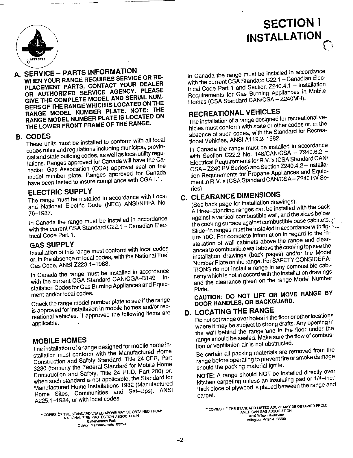
A. Mark the floor or wall where eitherthe right or left D. To check the range for proper installation of the
"EDGE" of the 30" opening is to be located, anti-tip bracket: Use a flashlight and look under-
B. Place the BRACKET SIDE, see figure 1, at the rear leveling legs is engaged in the bracket slot.
marked "EDGE" and against theback wall.
C. Use the bracket as a template and mark the re- structions provided with the range.
quired holes, as shown in figure 1, for the type of
construction you will be using.
footthat will engagethe ANTI-TIP bracket,seefig-
largepanof wateron thecooktop orthe oven rack.If
anadjustmentisrequiredpullthe range forward,tip
neaththe bottom of the rangeto see that one ofthe
E. Proceed with the remainder of the installation in-
STEP 2 - Anti-Tip Bracket Installation _"*-_
A. Wood Construction: ..... '
1. Floor:Locatethecenterofthetwo holesidenti- _ "_ _ _"
pilot holeinthe centerofeach hole(anailorawl
may be used if a drill is not available). Secure
the ANTI-TIP bracket to the floor with the two
screws provided. Proceedto STEP 3. '=_
2. Wall: Locate the center of the two holes identi- FIGURE1
fled in figure I as "WALL-PLATE". Ddll an an-
gled 1/8"pilot hole in thecenterof each holeas
Showninfigure2.(Anailorawl maybeusedifa
drill is not available). Secure the ANTI-TIP
bracket tothewa}lwiththe twoscrewsprovided
as shown in figure 2. Proceed to STEP 3.
B. Cement or Concrete Construction:
1. Suitable screws for concrete construction can
be obtained at the hardware store. Drill the re-
quired size hole forthe hardware obtained into
theconcrete atthe centerofthe holes identified
in figure 1 as "FLOOR--CEMENT". Secure the
ANTI-TIP bracket to the floor. Proceed to
STEP 3. FIGURE2
-3-
Page 4
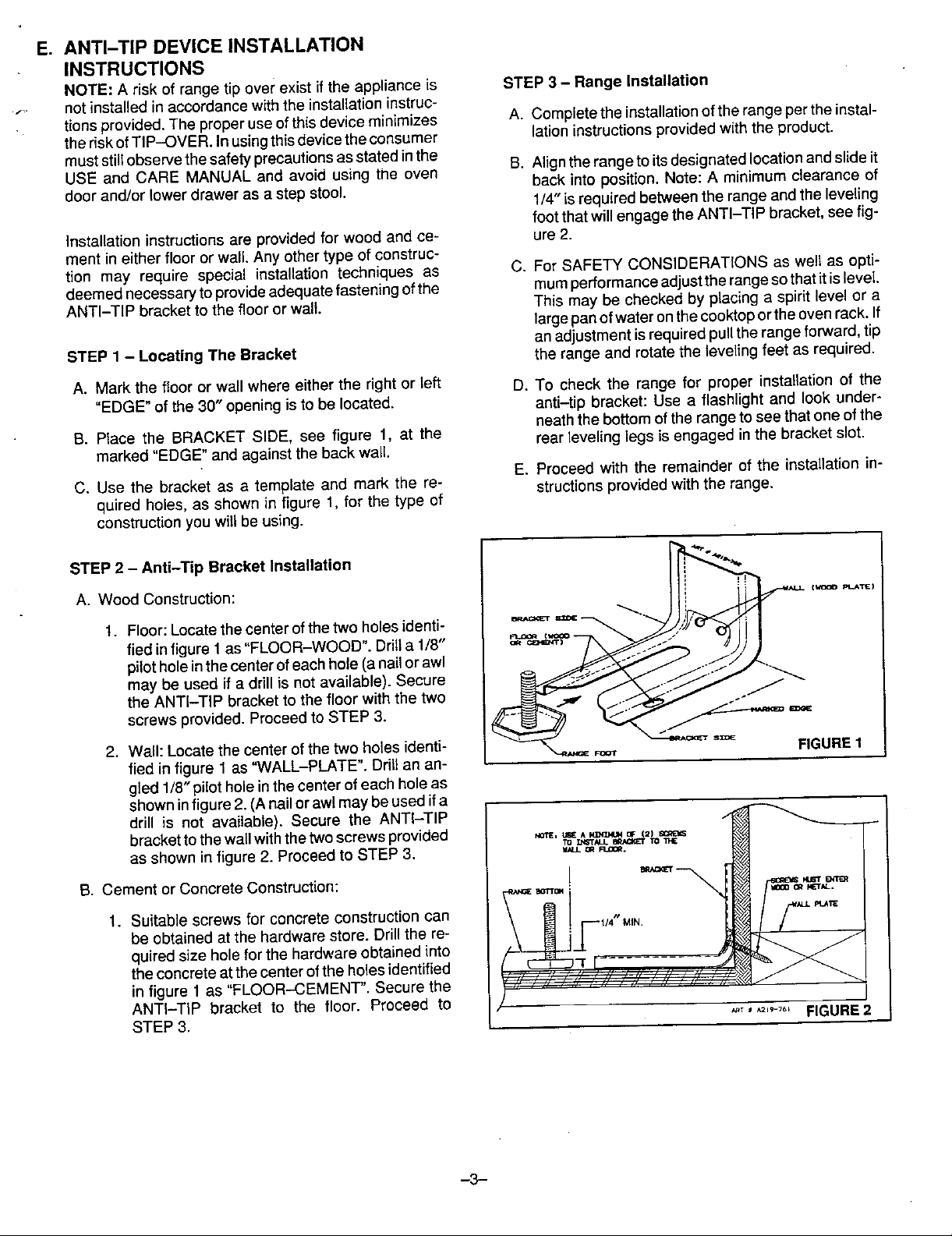
connecttherangeto the maingas supply mustbe
_- CLEAN,free of metalshavings, rust, dirt and liq-
uids(oil or water). Dirt,etc. in the supplylinescan
--_ I1_-- work its into the manifold and in turn
-" cause failure of the gas valves or controls and ,. :
clog burners andor pilot orifices.
way range #,-,.,,
._._ b. The house pipingand/or rangeconnectorusedto
FIGURE3
NOTE: THE MAINTOP DOES NOTLIFT UP.
c. Turn off allpilotsand maingasvalve of other gas
appliances.
d. Turn off main gas valve at meter.
F. CONNECTING THE RANGE e. Beforeconnecting range, applypipethread corn-
1, ELECTRICAL SUPPLY CONNECTION: pound approved for LPG to all threads.
The range requires 120 volts, 60 cycle alternating
current from an outlet capable of supplying 15 am- f. Connect range to gas supply at regulator using
peres, rigid pipe or adaptors supplied with flexible con-
nector. See rating platefor type of gas range has
been manufacturedfor. Gas conversion kits are
available.
g. Turnonmaingasvalveat meter,andrelightpilots
atother gas appliances.
h. Apply soap suds to the gas connection at range ----
plug. and check for leakage. Check for leakage at all __
gasconnections and fittings in the range.
CAUTION: NEVER CHECK FOR LEAKS WITH
A FLAME.
i. Connect electric supply cord to wall receptacle
120 volt, 60 cycle alternating current, at 15 am-
peres.
j. Adjust burner air shutter to the widest opening
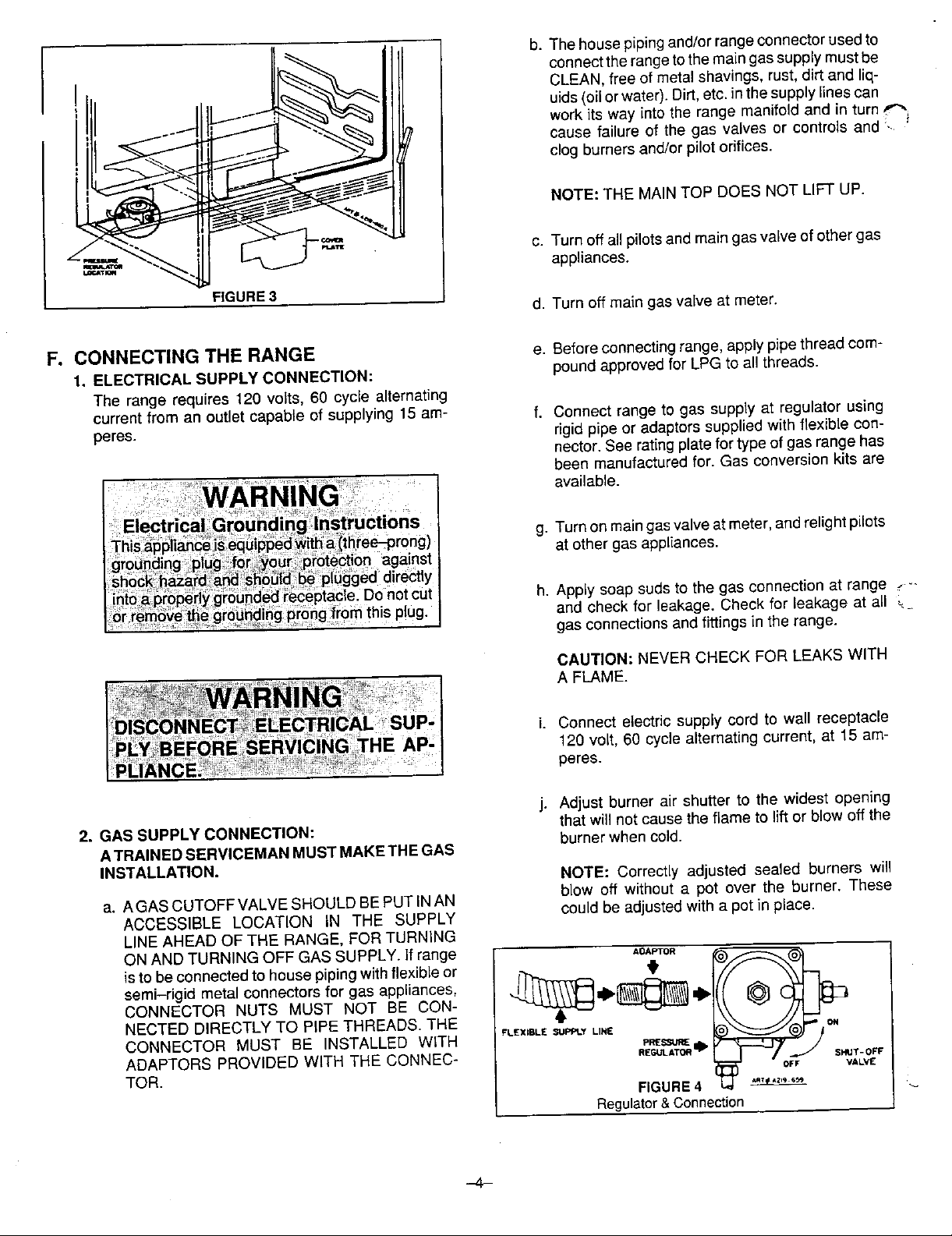
2. GAS SUPPLY CONNECTION: that willnot cause theflame toliftor blow off the
ATRAINEDSERVICEMAN MUSTMAKETHEGAS
INSTALLATION. NOTE: Correctlyadjusted sealed burners will
a. AGAS CUTOFFVALVE SHOULD BEPUT INAN blow off without a pot over the burner. These
ACCESSIBLE LOCATION IN THE SUPPLY could be adjustedwith a pot in place.
LINEAHEAD OF THE RANGE, FORTURNING
isto beconnectedtOhouse pipingwithflexible or _ _)_@1
CONNECTOR NUTS MUST NOT BE CON-
NECTED DIRECTLY TO PIPE THREADS. THE
semi-rigid metal connectors for gas appliances, /._4 d_._._Q _ _
CONNECTOR MUST BE INSTALLED WITH FLEXIBLESUPPLYLINE PRESCribE
ADAPTORS PROVIDED WITH THE CONNEC- _Ut-ATO"=II'
burnerwhencold.
OFF VALVE
T-OFF
ToR nG0,E, '
Regulator&Connection
-4-
Page 5

G. CHECKING MANIFOLD GAS PRESSURE
sure, remove right rear burner assembly by placing
burner wrench (part no. 8002P026-60, available from
your dealer orauthorizedservice agency*) oversurface
Ifitshouldbenecessarytocheckthemanifoldgaspres- _ORFICE HOO_j/_
burner assembly with ignitor positioned inside gap in
wrench ring(figure5A).This prevents ignitorfrom being
crushedwhenwrenchtightensonburner assembly.Ro- '_'_"
late burner assembly approximately one--eighth turn
counter-clockwise and lift from main top (figure 5B).
Connect manometer (water gauge) or other pressure _ ",._" _H
device to the top burner right rear orifice hood, using a ........x.._._._ _..<_'x_rubber hose with inside diameter of approximately 1/4"
inch,holdtubingdown tightover orifice hood. Turnburn-
er valve on. For an accurate pressure check have at
leasttwo (2)other top burners burning. Be surethe gas
supply (inlet) pressure is at least one inch (1") above
specified range manifold pressure. The gas supply
pressureshouldneverbeover 14 inches water column.
When properly adjusted for Natural Gas the water coF
FIGURE5B
umn pressure is 4", for LP Gas the water column pres-
sure is 10". Replace burner assembly in main top and
rotate approximately onc cighth turn clockwise using
burnerwrench untilburnerlockeinto positionwith ignitor
facing rearward. H, CHECKING PRESSURE OF HOUSE PIPING
SYSTEM
COUNTER-CLOCKNISE be disconnected fromthe gas supply piping system
t.OOSEN during any pressure testing of that system at test
1. The appliance and its individual shutoff valve must
pressuresinexcessof 1/2Ibs./sq.in.(3.5kPa) (13.8
I_NITOe_'OS_'rION 2. Theappliance must be isolatedfrom thegassupply
ZNSZOEWRENCHGAP pipingsystem by dosing its individual manualshutoff
valve during any pressure testing of the gassupply
piping system at test pressures equalto or lessthan
CLOCKWISE 1/2Ibs./sq. in, (3.5 kPa) (13.8 in. water column).
TO TIGHTEN ._._
.... ___ in. water column).
19-812
FIGURE5A
*If burner wrench is not available locally, contact Maycor Parts and Service, 240 Edward Street, Cleveland, TN 37311,
(61_72-3500).
-5-
Page 6

SECTION II
RANGE ADJUSTMENTS
A. TOP SECTION - ELECTRIC IGNITION
To operate, push and turn top burner knob to the LITE er flame wilt go "out" in 20 to 30 seconds after the
position. The top burner will light. To turn OFF spark af- ignitor goes "OFF". To maintain any given oven
ter the top burner has ignited: temperature this cycle will continue as long as the
dial (or display) is at the given temperature.
1. For ranges with SINGLE purpose valves, turn knob to
the right, clockwise to the HI setting, figure 6A. b. In case servicing should become necessary, a
2. For ranges with HI-SIM-WARM valves, turn knob, burner only. (See figures 3 and 4).
either direction to HI setting, figure 6B.
FIGURE 6A FIGURE 6B figure 7.
Single PurposeKnob Hi-Sim-Warm Knob
manual gas valve is supplied on the pressure
regulator to shut off the gas to the oven and broiler
c. The oven CANNOT be used during periods of
power outage. In case of power failure, turn the
2. AIR SHU'n'ER - OVEN BURNER
a. The approximate length of the flame on the oven
burner is 1/2 inch (distinct inner, blue flame). See
BURNER
3. There are separate ignition devices for each burner. BAFFLE_J-..._ "r_ "?_1/2"FLAME
These ignitors are turned "on" when any knob is _ _._.(,:,:/'<_" J-/- _C'",
setting. In case of an electrical power failure, the top
long as any of the top burner knobs are at the LITE ___
burners can still be used, To light a burner, hold a
turned to the LITE setting. The ignitors will "spark" as _ -- _ '---'
lighted kitchen match adjacent to the top burner to be
used and turn valve knob for the burner to LITE. USE
EXTREME CAUTION. The electric ignitor will not
come "on". It is necessary when using the top burners
during this type of emergency to light each burner to b. Oven burner flame can be checked as follows,
be used with a kitchen match as described above without burner baffle in place:
each and every time the burner or burners are to be
used. - Yellow flame on burner - open air shutter "2"
on figure 8.
B. OVEN ADJUSTMENTS - Distinctblueflamebutlifting-closeairshutter
1. ELECTRIC IGNITION - BAKE BURNER WITH "2" on figure 8.
ELECTRIC GLOW BAR
a. The bake burner is equipped with an electric con- c. The air shutter, figure 8, should be set approxF
trol system as well as an electric oven burner ig- mately 2/3 open for natural gas and full open on
niter. This control system requires NO adjust- LP gas.
ment. To operate, turn thermostat knob to any
temperature setting or to broil. Current will flow to
the ignitor. It will "glow" similar to a light bulb. (This
glow may be reflected into the oven through the LOCKSCREW
openings in the oven bottom). When the ignitor
hasreachedatemperature sufficienttoignitegas, AIR SHUTTER
the electrically controlled oven valve will open and /2
flame will appear at the oven burner. There is a ORIFtCEHOOO
time lapse from 30 to 45 seconds after the thermo- 1_..
stat is turned ON before flame appears at the
oven burner. When the oven has reached the dial
setting, the glowing ignitor will go OFF. The burn- FIGURE 8
--6-
FIGURE 7
\
Page 7

3, WAIST-HI BROILER BURNER
(See figure 9) The approximate length ofthe flame of the broil
a. The waist-hi broiler is equipped with its own burner is a distinct inner btue flame of 3/8 inch.
(separate) electric control system and electric Theouterflamewillextendoutwardasasheetof
broiler burner ignitor. To operate turn oven ther- flame adjacent to the burner baffle (flame
mostat knob to the BROIL setting. The system spreader) above the broil burner,figure 9.
functions the same as described under Bake
Burner. The airshutter, figure 8 should be setto full open
on both NaturalGas and on LPGas.
b, A manual gasshut-off valveissupplied,onregu- d. The waist-hi broiler CANNOT be used during
lator incase servicingshouldbecome necessary, periods of power outage. Incaseof power fail-
See figure 4. ure, turn thermostat tothe OFF position.
c. Theair shutter adjustmentsare thesameas illus- C. CLEAN CYCLE - SEE USE & CARE MAN-
trated in figure 8. UAL FOR SELF CLEAN INSTRUCTIONS.
WAIST HIGH
BROILER BURNER
FIGURE9
TypicalGas PipingSystem
YY<'
-7-
Page 8

SECTION III
GAS CONVERSION
A. GENERAL 1. Removethecap, pushdownandturncou te clock- "
All sealed burner ranges and cooktops are equipped wise. Turn the cap over and reinstall (figure 10).
with double coaxial (universal)orificesand with a con- NOTE: THE GASTYPE YOU ARE CONVERTING
vertible gas regulator. The unit model number plate TO MUST BE VISIBLEONTHE TOP OF THE IN-
states which gas it was adjusted for at thefactory. To STALLED REGULATORCAP.
convert the unit to either Naturalgas or LPgas will re-
quireadjustmentofthe surfaceburnerorifice hoods,ad- 2. Remove plasticdust cover from cap nut on top of
justment oftheoven orifice/airshutter and replacement regulator. Remove cap nut from regulator (plastic
and/or adjustment of the pressure regulator converter dust cover comes off with nut)."IMPORTANT" re-
cap. move plastic dust cover from cap nut and reinstall
on oppositeside of cap nut.
B, REGULATOR CONVERSION Reinstall cap nut to regulator and replace dust
The unit regulator must be set to match the type gas cover. "CAUTION" be sure marking for the type of
supply used. If converting from natural gas to LP gas, gas to which regulatorhasjust been converted is
the regulator must be converted to regulate LP gas. If visible intop ofcap nut beforereplacingplastic dust
converting from LP gas to natural gas, the regulator cover. See figure 11.
must be converted to regulatenatural gas.
3. Remove cap and forcibly snap out plastic plunger
TO CONVERTTHE PRESSURE REGULATORFROM from bottom of cap. Turn plunger over and forcibly
ONE GAS TO ANOTHER, DO EITHER (1), (2) OR (3) snap back in original location (figure 12). NOTE:
BELOW:YOUR UNITWILLBE EQUIPPEDWITHONE PLUNGER MUST SNAP INTO POSITION; THE
OF THE THREE REGULATOR TYPES SHOWN BE- GAS TYPE YOU ARE CONVERTING TO MUST
LOW. BEVISIBLE ON LOWER SIDE OF PLUNGER.
nr
FIGURE10 FIGURE11 FIGURE12
.-8-
Page 9

C. ORIFICE CONVERSION ORFICEHOeO.- +
a. Place burnerwrench(part no. 8002P026-60,
availablefromyourdealerorauthorizedservice
"+_ agency*)oversurface burnerassemblywithig-
1. FROM NATURAL GAS TO LP GAS: _._/_/
nitorpositioned insidegapinwrenchring(figure
13A).This prevents ignitor from being crushed
whenwrenchtightensonburnerassembly.Ro-
tate burner assembly approximately one-
top(figure 13B).Usinga 1/2"deep--wellsocket,
tighten each burner orifice hood approximately
two complete turns clockwise TO THE
eighthturncounter-clockwise and liftfrommain _. __ _.,
bly in main top and rotate approximately one-
CLOSED POSITION. Replace burner assem- _
eighthturn clockwise using burner wrench until
burner locks into position with ignitor facing
rearward. FIGURE13B
b. On ranges, use the 1/2" open end wrench to 2. FROM LP GAS TO NATURAL GAS:
tighten the oven orifice hood (1-figure 18) ap- a. Place burner wrench (part no. 8002P026-60,
proximatelytwo complete turns clockwiseTO ava(labIefromyourdealerorauthorizedservice
THE CLOSED POSITION. See figure 14B. agency*) oversurfaceburnerassembly with ig-
nitorpositionedinsidegapinwrenchring (figure
13A).This preventsignitorfrom be{ngcrushed
c. Adjustburner air shutter to the widest opening whenwrench tightenson burner assembly. Ro-
tate burner assembly approximately one--
thatwiiJnot causetheflame to liftor blowoffthe eighthturn counter-clockwiseandIiftfrommain
burnerwhen cold. top(figure 13B).Usinga 1/2"deep-well socket,
NOTE; Correctly adjusted sealed burners will looseneach burner orificehood approximately
blow off without a pot over the burner. These two complete turns counter-clockwise. Re-
should be adjusted with a pot in place, place burner assembly in main top and rotate
approximatelyone eighthturnclockwise using
burner wrench until burner locks into position
with ignitor facing rearward.
LOOSEN b. On ranges, use the 1/2" open end wrench to
-CLOCKWISE
loosenthe oven orifice hood (1-figure 18) ap-
wise until the flames on the burner do not in-
_ _"-_----*_Z_-_-...__ .]. proximatelytwo completeturnscounter-clock-
IGNITORPQSlTION - crease in length.See figure 14A.
INSIDE WRENCH GAP
thatwill notcausethe flametoliftor blowoffthe
CLOCKWZSE burner when cold.
TOTIGHTEN ._._ NOTE: Correctly adjusted sealed burners will
blow off without a pot over the burner. These
___ c. Adjustburner airshutter to the widest opening
ZN-t4_JSE_ _ - I_MOV_L
9-8L2 should be adjusted with a pot in place.
FIGURE13A
HOOD HOOD
ORIFICE ORIFICE
FIGURE14A FIGURE14B
*If burner wrench is not available local)y, contact NATURALGAS LPGAS
Maycor Parts and Service, 240 Edward Street, SE'r'rING SETTING
Cleveland, TN 37311. (615-472-3500).
-9--
Page 10

D. TOP BURNER "WARM" ADJUSTMENT E. OVEN BURNER AIR SHUTTER
Ifequipped witha single purpose valve (see figure 15) ADJUSTMENT
no adjustment is required. If equipped with HI, SIM, Theapproximate length of the distinct inner blue flame
WARM valves, the burner flame atthe WARM position of the oven burner is 1/2 inch (figure 17).Remove the,
should extendto the outer edge of the lipof the burner burnerbaffleto adjustthe burnerflame with the air shut-
cap. The WARM settingshould be such that a stable ter. Theair shutter (figure18)should be approximately
flame is maintainedonthe burnerwhenturningthe knob 2/3open for naturalgas andapproximatelyfull open on
from HIto WARM. If itshould be necessaryto increase LPgas. If the oven burner flame isyellow, open the air
or decrease the flame at the WARM setting, operate shutter until it is distinct and blue. If the oven burner
burner at HI position for approximately five minutes, flame isdistinctandblue but lifting,closethe air shutter
Turn knobtoWARM(seefigure 16).Removevalveban- until the lifting stops.
die and with a small screwdrivermake the desired ad-
justment by turning adjustment screw "A" (figure 16). , .
BURNER
A FIGURE 17
FIGURE 15 FIGURE 16 LOCK SCREW i
\
ORIFICE HOOD ,-/"2
RGURE18
i
AIR SHUTTER
-10-
Page 11

SECTION IV
INSTALLATION DRAWINGS
FREE STANDING RANGES
Range may be installed with zero inches clearance adjacent to (against) combustible construction at the rear and on the
sides below the cooktop.For clearence for wall cabinets above a free-standing conventional range cooktep see illustration
and dimensions given below. Wall cabinets can be installed above and adjacent to a range, with elevated oven as illustrated.
*NOTE: 30 inch dimension between cooking top and wall cabinet shown on illustration does not apply to ranges with an
elevated oven. The 30 inch dimension may be reduced to not less than 24 inches when the wall cabinets in a domestic home
are protected with fireproof materials in accordance with American National Standards - National Fuel Gas Code or in mo-
bile homes when they are protected with fireproof materials in accordance with the Manufactured Home Construction and
Safety Standard (see Section I (B) codes).
CAUTION: Some cabinets and building materials are not designed to withstand the heat produced bythe normal safe opera-
tion of a listed appliance. Discoloration or damage, such as delamination, may occur.
TABLE NO.1
DIMENSION A DIMENSIONB DIMENSIONC LOWERCABINET
WIDTH OF NO LESS THAN WIDTH DEPTH & CUTOUT
RANGESERIES NUMBER RANGES OF RANGES
30" Free Standing, Self Clean 30"** 30" 3"* Figure 19B
30" Slide-In, Self Clean 30.... 30" 3"* Figure 19C
FOR DIMENSIONS A, B & C - SEE TABLE NO. 1
FRONT VIEW DETAIL
FIGURE 19A
INSTALLATION ILLUSTRATION FREE STANDING RANGES
-11-
Page 12

,To,_"Y,_'o'_oP
(BOTH SIDES)
PROVIDE FOR IZO¥
HEl_Cr A,RF.A (xn'LET MUST BE
I I Ot,II'I.ET IN 'THaSGENERAL
24' _
t K
**, THIS AREA.
_SO 21t "_--GAS RIPE TO BE IN
CABINt'T _ _'_"
WRH LEVELIN_I LEGS _,-"" ART_A2_-657
COMPt.STELT IN,
FIGURE 19B
Gas Free-Standing Ranges
SERIES I WIDTH HEIGHT DEPTH WIDTH HEIGHT DEPTH WIDTH HE/GHT DEPTH WT. (LBS.)
Self Clean 22" ";2 1/2" 18" 13 1/2" 3 1/4" 15" 30" 36" 24" 215
_ENINS_
OVEN BROILER CUTOUT DIMENSIONS APPROX.
SHIPPING
=s" _ , . _NOTE
1NORMALC&BINET __ 7,- P.3___ USE THIS OIM,WHEN _ ON CABINET TOPS WITH
DEPTH TRIM STRIP _ NOT USED.
STRIPo.K.Os_s_..o . _oSECT.O.
_KIT. TO CLEAR TOP.
BE FLUSH.
_ GAS PlPg TO BE IN THIS AREA.
Ik'_ _ LEVELIMe LEeS r,*,,z,9.6_
FIGURE 19C
Gas Slide-In Ranges
OVEN BROILER CUTOUT DIMENSIONS APPROX.
SERIES WIDTH HEIGHT DEPTH WIDTH HEIGHT DEPTH WIDTH HEIGHT DEPTH WT.(LBS.)
SHIPPING
Self Clean 22" 12 1/2" 18" 13 1/2" 3 1/4' 15" 30" 36" • 210
-12-
 Loading...